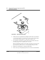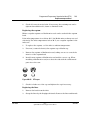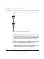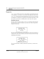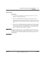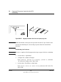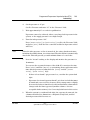
1
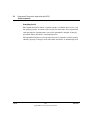
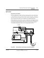
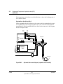
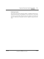
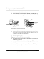
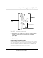
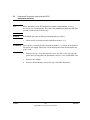
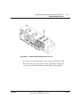
240
Programmed Temperature
Vaporization Inlet (PTV)
Theory of operation
The Programmed Temperature Vaporization (PTV) Inlet collects each portion
of an injected sample inside a 120 microliter liner until the entire quantity of
sample is obtained. During the hold, the sample is held at a programmable
temperature as low as –60°C using CO2 cooling, or as low as –160°C using
liquid nitrogen. When the complete sample is collected, the PTV heats and
delivers the sample onto the column.
The PTV can be used with either a septum or septumless head, operating in
either split, splitless, or solvent vent modes.
In the solvent vent mode, analytes are thermally trapped in the liner while
the solvent is removed. With the solvent gone, the liner volume can be used
for another injection. Injection can be repeated several times to concentrate
the analytes from a large sample volume. After injection and solvent removal,
the analytes are transferred to the column. This can replace the need for
offline reconcentrating and minimize loss of sample.
Operating modes
The Agilent Programmed Temperature Vaporization (PTV) Inlet System has
five operating modes:
•
•
•
•
•
Jun 2001
The split mode is generally used for major component analyses.
The pulsed split mode is like the split mode, but applies a pressure pulse
to the inlet during sample introduction to speed the transfer of material
onto the column.
The splitless mode is used for trace analyses.
The pulsed splitless mode provides a pressure pulse during sample
introduction.
The solvent vent mode collects analyte in the liner while venting solvent,
and is used for large volume injection. Either single or multiple injections
can be made for each run.
Inlets
Agilent 6890 Gas Chromatograph Service Manual
1 of 46
240
Programmed Temperature Vaporization Inlet (PTV)
Theory of operation
Sampling heads
The septum head uses either a regular septum or a Merlin microseal to seal
the syringe passage. A stream of gas sweeps the inner side of the septum and
exits through the septum purge vent on the pneumatics module. It may be
used with either automatic or manual injection.
The septumless head uses a check valve instead of a septum to seal the syringe
entrance passage. It may be used with either automatic or manual injection.
2 of 46
Inlets
Agilent 6890 Gas Chromatograph Service Manual
Jun 2001
Programmed Temperature Vaporization Inlet (PTV)
Split modes
240
Split modes
Septum head installed
In the two split modes—with or without a pressure pulse—the solenoid valve
is open and divides the gas stream entering the inlet between the column flow,
the split vent flow through the solenoid valve, and the septum purge flow. The
ratio of the split vent flow to the column flow is called the split ratio.
Figure 240-1 shows the inlet flow control. Overall carrier and sample gas flow
is controlled by the first proportional valve and the flow sensor. The solenoid
valve is open, and proportional valve 2 acts as a back pressure regulator
controlled by the pressure sensor on the septum purge vent line.
Split SPR
vent vent
SPR
PS
Flow
Total flow
limiting control loop
frit
PV2
Valve
open
Trap
Septum
holder
FS
PV1
Temperature
conversion
board
Cryo
valve
Figure 240-1
Jun 2001
To detector
Split mode flow control diagram (septum head installed)
Inlets
Agilent 6890 Gas Chromatograph Service Manual
3 of 46
240
Programmed Temperature Vaporization Inlet (PTV)
Split modes
The temperature of the liner can be held below or above the boiling point of
the carrier solvent.
Septumless head installed
In the septumless head, the flows are the same as in the septum head, except
the septum purge vent is bypassed directly to the carrier flow through the
gang fitting on the flow manifold. Flow control is the same as for the septum
head. See Figure 240-2.
Split
vent
SPR
vent
SPR
PS
Flow
Total flow
limiting
control loop
frit
Trap
Septumless
head
PV2 Valve
open
FS
PV1
Temperature
conversion
board
Cryo
valve
Figure 240-2
4 of 46
To detector
Split mode flow control diagram (septumless head installed)
Inlets
Agilent 6890 Gas Chromatograph Service Manual
Jun 2001
Programmed Temperature Vaporization Inlet (PTV)
Split modes
240
Pulsed split modes
The pressure pulse modes (using the septum- or septumless head) increase
inlet pressure just before the beginning of a run and return it to the normal
value after a specified time. The pulse sweeps the sample out of the inlet and
into the column faster, reducing the chance for sample decomposition in the
inlet.
Jun 2001
Inlets
Agilent 6890 Gas Chromatograph Service Manual
5 of 46
240
Programmed Temperature Vaporization Inlet (PTV)
Splitless modes
Splitless modes
In splitless mode—with or without a pressure pulse—the solenoid valve is
closed during injection and vaporization of the sample and while the sample
transfers to the column. At a specified time after injection, the valve opens
to sweep vapors left in the liner out the split vent to prevent solvent tailing
due to the large inlet volume and small column flow rate.
Figure 240-3 shows the inlet flow control during injection and sample transfer
with the septum head installed. The flow sensor measures the flow rate, but
the pressure sensor on the septum purge line controls the column head
pressure using proportional valve 1.
In the septumless head, the flows are the same as in the septum head except
the septum purge vent is bypassed directly to the carrier flow through the
6 of 46
Inlets
Agilent 6890 Gas Chromatograph Service Manual
Jun 2001
Programmed Temperature Vaporization Inlet (PTV)
Splitless modes
240
gang fitting on the flow manifold. Flow control is the same as for the septum
head.
Split SPR
vent vent
Column head
pressure
control loop
SPR
PS
Flow
limiting
frit
Trap
PV2
Septum
holder
Valve
closed
FS
PV1
Temperature
conversion
board
Cryo
valve
Figure 240-3
To detector
Splitless mode flow control diagram: sample injection
After the injection, the solenoid valve opens and the flow control is the same
as during split mode operation. See Figure 240-1 (or Figure 240-2).
Jun 2001
Inlets
Agilent 6890 Gas Chromatograph Service Manual
7 of 46
240
Programmed Temperature Vaporization Inlet (PTV)
Splitless modes
Pulsed splitless mode
The pressure pulse modes (using the septum- or septumless head) increase
inlet pressure just before the beginning of a run and return it to the normal
value after a specified amount of time. The pressure pulse sweeps the sample
out of the inlet and into the column faster, reducing the chance for sample
decomposition in the inlet.
8 of 46
Inlets
Agilent 6890 Gas Chromatograph Service Manual
Jun 2001
Programmed Temperature Vaporization Inlet (PTV)
Solvent vent mode
240
Solvent vent mode
Stage 1: Sample and vent
In solvent vent mode, the sample is injected into a cold inlet. During sampling,
and for the duration of the venting, the solenoid valve is open. The solvent
vaporizes and is swept out the vent, while the sample deposits on the liner
walls or packing. If conditions are properly chosen and the sample is suitable,
analytes deposit in the inlet liner while the solvent evaporates and is swept
out. Large or multiple injections can be used to concentrate sample in the
inlet before transferring it to the column for analysis. Figure 240-4 shows the
inlet flow control with the septum head installed.
In the septumless head, the flows are the same as in the septum head except
the septum purge vent is bypassed directly to the carrier flow through the
Jun 2001
Inlets
Agilent 6890 Gas Chromatograph Service Manual
9 of 46
240
Programmed Temperature Vaporization Inlet (PTV)
Solvent vent mode
gang fitting on the flow manifold. Flow control is the same as for the septum
head.
Split SPR
vent vent
SPR
PS
Flow
Total flow
limiting
control loop
frit
Trap
Septum
holder
PV2 Valve
open
FS
PV1
Temperature
conversion
board
Cryo
valve
Figure 240-4
10 of 46
To detector
Solvent vent mode flow control diagram: sample and vent
Inlets
Agilent 6890 Gas Chromatograph Service Manual
Jun 2001
Programmed Temperature Vaporization Inlet (PTV)
Solvent vent mode
240
Stage 2: Sample transfer
When solvent venting ends, the solenoid valve closes and the inlet heats to
the final temperature. The sample transfers onto the capillary column.
Split SPR
vent vent
Column head
pressure
control loop
SPR
PS
Flow
limiting
frit
Trap
PV2
Septum
holder
Solenoid
valve closed
FS
PV1
PTV thermocouple PCB
Cryo
valve
Figure 240-5
Jun 2001
To detector
Solvent vent mode flow control diagram: sample transfer
Inlets
Agilent 6890 Gas Chromatograph Service Manual
11 of 46
240
Programmed Temperature Vaporization Inlet (PTV)
Solvent vent mode
Stage 3: Purge and cleanup
The solenoid valve opens again and the system returns to the Stage 1
configuration but with different setpoints. The PTV inlet is flushed through
the split vent.
Split SPR
vent vent
SPR
PS
Flow
Total flow
limiting
control loop
frit
PV2
Valve
open
Trap
Septum
holder
FS
PV1
PTV thermocouple PCB
Cryo
valve
Figure 240-6
12 of 46
To detector
Solvent vent mode flow control diagram: purge and cleanup
Inlets
Agilent 6890 Gas Chromatograph Service Manual
Jun 2001
Programmed Temperature Vaporization Inlet (PTV)
Replacement procedures
240
Replacement procedures
In addition to the PTV consumables (inlet adapters, columns, Teflon ferrules,
and septa), the replacement parts in the PTV inlet assembly are:
•
•
•
•
•
•
The entire PTV inlet, pneumatics, and manifold assembly
The PTV manifold assembly
PTV gang weldment and front trap assemblies
The filter
The head assembly (septum or septumless)
The cryo shroud on the inlet body (CO2 or liquid nitrogen)
•
•
The PTV thermocouple PCB
The O-rings and restrictors in the gang fitting assembly.
Replacing the PTV inlet, pneumatics, and manifold
The entire PTV assembly can be easily replaced.
1.
WARNING
Jun 2001
Turn off the oven and the inlet and allow them to cool.
Turn off the oven and the inlet and allow them to cool. Turn off all flows at
the initial gas supply. Then turn off the main power switch and unplug the
power cord.
2.
Remove the top cover, the inlet fan cover, the inlet cover, the left side
panel, the top rear panel, the pneumatics chassis cover, and the RFI cover.
3.
Remove the top mounting screw in the PTV manifold assembly.
Inlets
Agilent 6890 Gas Chromatograph Service Manual
13 of 46
240
Programmed Temperature Vaporization Inlet (PTV)
Replacement procedures
Figure 240-7
14 of 46
Removing the PTV manifold assembly
4.
Remove the column.
5.
Loosen the three captive Torx screws which secure the inlet to the oven,
and lift the PTV inlet out of the oven.
Inlets
Agilent 6890 Gas Chromatograph Service Manual
Jun 2001
Programmed Temperature Vaporization Inlet (PTV)
Replacement procedures
240
Loosen screws
Figure 240-8
6.
Removing the PTV inlet
Remove the heater connector from the side panel.
Remove
connectors
Disconnect cable
Figure 240-9
Jun 2001
PTV electrical connectors
Inlets
Agilent 6890 Gas Chromatograph Service Manual
15 of 46
240
Programmed Temperature Vaporization Inlet (PTV)
Replacement procedures
7.
Disconnect the power cable, thermocouple connector, and cryo connector
from the flow module and board. Disconnect the module ribbon cable
from the pneumatics board.
8.
Slide the flow module out of the chassis, remove the chemical trap
assembly from the mounting bracket, and remove the PTV assembly from
the GC.
9.
Removing the entire PTV assembly.
10. Replace the PTV assembly and flow module and re-assemble in reverse
order.
Replacing the PTV with cooling assembly
The PTV with cooling assembly, shown in Figure 240-10, is generally the
lowest level replacement part.
Figure 240-10
1.
16 of 46
PTV with cooling assembly
Turn off the inlet and allow the inlet to cool.
Inlets
Agilent 6890 Gas Chromatograph Service Manual
Jun 2001
Programmed Temperature Vaporization Inlet (PTV)
Replacement procedures
WARNING
Caution
240
Turn off the oven and the interface and allow them to cool. Turn off all flows
at the initial gas supply. Then turn off the main power switch and unplug the
power cord.
2.
Remove the top cover, the inlet fan cover, the inlet cover, the left side
panel, the top rear panel, the pneumatics chassis cover.
3.
Remove the column.
4.
Loosen the three captive Torx screws which secure the inlet to the oven,
and lift the PTV inlet out of the oven.
When removing/attaching the inlet cryo line, use one wrench to support the
cryo line fitting on the inlet body and one to tighten the nut. Failure to do
this could break the fitting on the inlet.
Remove gas
lines
Figure 240-11
5.
Jun 2001
Removing the gas lines from the inlet
Disconnect the carrier gas line to the inlet at the inlet. Remove the split
vent gas line, and the septum purge line (as applicable). Using two
wrenches, remove the cryo fitting from the inlet.
Inlets
Agilent 6890 Gas Chromatograph Service Manual
17 of 46
240
Programmed Temperature Vaporization Inlet (PTV)
Replacement procedures
6.
Remove (unscrew) the head from the inlet.
7.
Remove the heater connector from the side panel, and remove the cryo
connector from the thermocouple conversion board at the back of the GC.
Remove
connectors
Disconnect cable
Figure 240-12
PTV electrical connections
8.
Replace the PTV inlet assembly and reassemble in reverse order. To attach
the cryo line to the new inlet assembly, tighten the nut finger tight, then
1⁄4 turn more using two open end wrenches.
9.
Check the system for leaks.
Replacing the CO2 or LN2 inlet cryo assembly
18 of 46
1.
Once the PTV with cooling assembly is removed, the cryo assembly on
the inlet can be replaced.
2.
Remove the PTV inlet as described under Replacing the PTV with cooling
assembly.
3.
Remove the three screws on the cryo assembly from the PTV inlet, and
remove the cryo assembly.
Inlets
Agilent 6890 Gas Chromatograph Service Manual
Jun 2001
Programmed Temperature Vaporization Inlet (PTV)
Replacement procedures
240
PTV inlet
PTV inlet with cooling
assembly
Inlet cryo assembly
Remove screws
Figure 240-13
Removing the inlet cryo assembly
4.
Install the new cryo assembly over the inlet body. Be sure to align the
assembly so that the fitting is closest to the wires, as shown in
Figure 240-12.
5.
Reassemble in reverse order.
6.
Check for leaks.
Replacing the PTV manifold assembly
The PTV manifold assembly is available as a replacement part with or without
the connected plumbing. When replacing just the manifold, the plumbing is
removed at the manifold outlet block. When replacing the plumbing and
manifold, the plumbing is disconnected from the inlet.
Jun 2001
Inlets
Agilent 6890 Gas Chromatograph Service Manual
19 of 46
240
Programmed Temperature Vaporization Inlet (PTV)
Replacement procedures
Note
When installing a new PTV manifold assembly and plumbing, it is not
necessary or recommended to disconnect the plumbing from the module. The
system is leak tested at the factory.
Caution
Follow ESD precautions when performing this procedure.
1.
WARNING
20 of 46
Turn off the oven and the inlet and allow them to cool.
Turn off the oven and the inlet and allow them to cool. Turn off all flows at
the initial gas supply. Then turn off the main power switch and unplug the
power cord.
2.
Remove the top cover, the inlet fan cover, the inlet cover, the left side
panel, the top rear panel, the pneumatics chassis cover, and the RFI cover.
3.
Remove the column.
4.
Remove the mounting screw in the top of the PTV manifold.
Inlets
Agilent 6890 Gas Chromatograph Service Manual
Jun 2001
Programmed Temperature Vaporization Inlet (PTV)
Replacement procedures
Figure 240-14
5.
Jun 2001
240
Removing the manifold mounting screw
Disconnect the manifold ribbon cable from the pneumatics PCB.
Disconnect the cryo cable, power cable, and thermocouple cable
connectors from the PTV thermocouple PCB on the manifold.
Inlets
Agilent 6890 Gas Chromatograph Service Manual
21 of 46
240
Programmed Temperature Vaporization Inlet (PTV)
Replacement procedures
Filter and O-rings
(2) (not shown)
PTV front trap
assembly
Filter and O-rings
(2) (not shown)
PTV SMLS
gang weldment
PTV front trap
assembly
Figure 240-15
PTV plumbing assemlies
Removing both the manifold and plumbing assemblies
22 of 46
1.
Loosen the three captive Torx screws which secure the inlet to the oven,
and lift the PTV inlet out of the oven.
2.
Disconnect the carrier gas supply line, split vent line, and septum purge
line (for the septum head) from the inlet. Straighten the tubing at the
manifold so that the manifold can be easily removed from the chassis.
Inlets
Agilent 6890 Gas Chromatograph Service Manual
Jun 2001
Programmed Temperature Vaporization Inlet (PTV)
Replacement procedures
240
3.
Lift the filter trap from the LCO2 bracket and then slide the manifold
assembly out of the chassis.
4.
Replace the manifold assembly and plumbing and reassemble in reverse
order.
5.
Check the system for leaks.
Removing the PTV manifold only
1.
Remove the plumbing block from the front of the manifold by removing
the screws.
2.
Inspect the O-rings in the block for damage and replace if necessary.
3.
Slide the manifold from the chassis and replace.
4.
Installation is the reverse of removal.
5.
Check the system for leaks.
Replacing the plumbing assemblies
1.
WARNING
Jun 2001
Turn off the oven and the inlet and allow them to cool.
Turn off the oven and the inlet and allow them to cool. Turn off all flows at
the initial gas supply. Then turn off the main power switch and unplug the
power cord.
2.
Remove the top cover, the inlet fan cover, the inlet cover, the top rear
panel, and the pneumatics chassis cover.
3.
Remove the column.
4.
Loosen the three captive Torx screws which secure the inlet to the oven,
and lift the PTV inlet out of the oven.
5.
To replace the PTV gang weldment, disconnect the plumbing block from
the PTV manifold assembly. Then, disconnect the carrier gas line and the
septum purge line (septum head only) from the inlet. Unscrew the filter
trap assembly and remove the PTV gang weldment assembly.
Inlets
Agilent 6890 Gas Chromatograph Service Manual
23 of 46
240
Programmed Temperature Vaporization Inlet (PTV)
Replacement procedures
6.
To replace the PTV front trap assembly, disconnect the split vent line
from the inlet. Unscrew the filter assembly and remove the PTV front trap
assembly.
Filter and O-rings
(2) (not shown)
PTV front trap
assembly
Filter and O-rings
(2) (not shown)
PTV front trap
PTV SMLS
gang weldment
assembly
Figure 240-16
24 of 46
PTV plumbing assemblies (septumless head shown)
7.
Inspect the O-rings and filter in the filter trap, and replace if necessary.
8.
If replacing the PTV gang weldment, install new O-rings in the manifold
plumbing block.
Inlets
Agilent 6890 Gas Chromatograph Service Manual
Jun 2001
Programmed Temperature Vaporization Inlet (PTV)
Replacement procedures
9.
240
Replace the gang weldment or front trap assembly and reassemble in
reverse order.
10. Check the system for leaks.
Replacing a gang fitting restrictor or O-ring
1.
WARNING
Turn off the oven and the inlet and allow them to cool.
Turn off the oven and the inlet and allow them to cool. Turn off all flows at
the initial gas supply. Then turn off the main power switch and unplug the
power cord.
2.
Remove the top cover, the inlet fan cover, the inlet cover, and the
pneumatics chassis cover.
3.
Remove the screw in the gang fitting. Gently tap the fitting to remove the
restrictor for cleaning/replacement. Inspect the O-rings and replace if
necessary.
4.
Reassemble in reverse order.
Check the plumbing for leaks.
Replacing the PTV thermocouple PCB
Caution
Follow ESD precautions when performing this procedure.
WARNING
Turn off the oven and the inlet and allow them to cool. Turn off all flows at
the initial gas supply. Then turn off the main power switch and unplug the
power cord.
Jun 2001
1.
Remove the top cover, the inlet fan cover, the inlet cover, the left side
panel, the top rear panel, the RFI cover, and the pneumatics chassis cover.
2.
Remove the PTV manifold as described in Replacing the PTV manifold
assembly.
Inlets
Agilent 6890 Gas Chromatograph Service Manual
25 of 46
240
Programmed Temperature Vaporization Inlet (PTV)
Replacement procedures
3.
Once the PTV manifold is removed, remove the two mounting screws that
secure the thermocouple conversion board onto the pneumatics board,
and remove the board.
PTV manifold assembly
PTV thermocouple PCB
Remove
2 screws
Figure 240-17
Replacing the PTV thermocouple PCB
4.
Replace the board and reassemble in reverse order.
5.
Check the system for leaks.
Replacing the filter
26 of 46
1.
Turn off the GC oven and the inlet and allow them to cool.
2.
Set all GC flows to zero.
3.
Remove the pneumatics cover.
Inlets
Agilent 6890 Gas Chromatograph Service Manual
Jun 2001
Programmed Temperature Vaporization Inlet (PTV)
Replacement procedures
240
4.
Lift the filter trap from the mounting bracket and unscrew the filter trap
assembly.
5.
Remove the old filter and O-rings and replace them.
6.
Reassemble the trap.
Replacing the inlet adapter
The Graphpack–2M connector (the inlet adapter) at the bottom of the inlet is
sized to the column diameter. When installing a different diameter column,
change the adapter.
The adapter number is stamped on the side of the adapters. Select the smallest
hole diameter that will accept the column.
Column
ID
Inlet adapter
number
Quantity
Part no.
200 mm
31
1
5182-9754
250 mm
45
1
5182-9761
320 mm
45
1
5182-9761
530 mm
70
1
5182-9762
1.
Unscrew the column nut from the adapter. Remove the nut and the
column from the inlet.
2.
With a 6 mm wrench, remove the inlet adapter, being careful not to lose
the silver seal inside. Save the adapter for later use.
3.
Select the appropriate inlet adapter for the column to be installed. Insert
a new silver seal (part no. 5182-9763, package of five) into the adapter
and screw the adapter onto the inlet fingertight. Tighten the adapter an
additional 1/16 to 1/8 turn.
Be careful not to overtighten the adapter. The inlet can be damaged if the
adapter is forced. If the adapter leaks, check the silver seal and replace
it if necessary.
Jun 2001
Inlets
Agilent 6890 Gas Chromatograph Service Manual
27 of 46
240
Programmed Temperature Vaporization Inlet (PTV)
Replacement procedures
Installing the column
Graphpack–2M ferrules are sized to the column outer diameter.
28 of 46
Column
ID
Graphpack ferrule
hole ID
Quantity
Part no.
200 mm
0.31 mm
10
5182-9756
250 mm
0.40 mm
10
5182-9768
320 mm
0.45 mm
10
5182-9769
530 mm
0.70 mm
10
5182-9770
1.
Place the appropriate Graphpack ferrule onto the column inlet end and
pull it at least 30 mm from the end.
2.
With a glass knife or other fused silica cutter, remove approximately 10
mm from the column end to eliminate graphite contamination.
3.
Position the ferrule so that it is 17 mm from the column end. Place a small
mark (typewriter correction fluid is useful) at the back of the ferrule and,
making sure that the column is correctly positioned, insert the column
end into the adapter.
Inlets
Agilent 6890 Gas Chromatograph Service Manual
Jun 2001
Programmed Temperature Vaporization Inlet (PTV)
Replacement procedures
240
22
17 mm
0
Mark column here
Figure 240-18
4.
Column installation
Screw the column nut on fingertight. Use a wrench to tighten the column
nut 1/8 to 1/4 turn. Be careful not to overtighten.
Removing the septumless head
Jun 2001
1.
Cool the inlet to room temperature.
2.
Disconnect the carrier gas line.
3.
Unscrew the septumless head counterclockwise from the inlet.
4.
Screw the new head onto the inlet. Tighten it 1/8 turn past finger tight.
Inlets
Agilent 6890 Gas Chromatograph Service Manual
29 of 46
240
Programmed Temperature Vaporization Inlet (PTV)
Replacement procedures
Figure 240-19
Removing the carrier gas line
5.
Reconnect the carrier gas line.
6.
Check all connections on the sampling head for leaks. If necessary, tighten
them again by hand.
Cleaning the septumless head
Minor deposits from sample mixtures can collect in the head. Dust and
abraded material particles can enter together with the syringe needle,
eventually causing leaks.
30 of 46
1.
Disconnect the carrier gas line and unscrew the head from the inlet.
2.
Unscrew the sealing element from the head. Carefully remove the Viton
seal and the pressure spring. Do not use a sharp object to extract the
valve body—this can leave scratches that cause leaks.
Inlets
Agilent 6890 Gas Chromatograph Service Manual
Jun 2001
Programmed Temperature Vaporization Inlet (PTV)
Replacement procedures
Figure 240-20
Jun 2001
240
Disassembling the septumless head
3.
Unscrew the guide cap from the head and remove the Teflon ferrule.
4.
Carefully insert a syringe with a 23 gauge needle into the head to press
the valve body (with the Kalrez seal) slightly out of the head. Carefully
tap the head on a soft smooth surface so that the valve body falls out
completely or slips out far enough to grasp it with your fingers.
5.
Remove the seal from the valve body.
6.
Carefully clean all components in hexane.
7.
Inspect the Teflon ferrule, seals, and valve body for damage, and replace
if necessary.
8.
Assemble the head in reverse order. Make sure that you work absolutely
lint-free and that the seals and the pressure spring are not damaged.
Inlets
Agilent 6890 Gas Chromatograph Service Manual
31 of 46
240
Programmed Temperature Vaporization Inlet (PTV)
Replacement procedures
9.
Check the entire system again for leaks; if necessary, carefully retighten
the guide cap with the syringe needle inserted slightly more and/or
replace the Kalrez seal.
If the head leaks when a syringe is inserted, the Teflon ferrule is the
problem. If the head leaks without a syringe inserted, the seals may need
to be replaced.
Replacing the Teflon ferrule
1.
Unscrew the guide cap from the septumless head and remove the Teflon
ferrule.
Figure 240-21
32 of 46
Installing a Teflon ferrule
Inlets
Agilent 6890 Gas Chromatograph Service Manual
Jun 2001
Programmed Temperature Vaporization Inlet (PTV)
Replacement procedures
240
2.
Push the guide cap and the new Teflon ferrule over the syringe needle so
that at least 10 mm of the needle tip is exposed.
3.
Guide the end of the syringe needle into the septumless head until the
ferrule meets the septumless head.
4.
Tighten the guide cap until resistance is first felt.
5.
Check for leaks when the syringe needle has been fully introduced.
6.
If necessary, carefully tighten the guide cap until the inlet stops leaking.
Removing/replacing the septum head
The septum head connects to the inlet via a free-spinning retaining nut.
Jun 2001
1.
Turn off the inlet heater and allow it cool.
2.
If replacing the septum head, disconnect the split vent and septum purge
lines.
3.
Use a 5/8-inch wrench to loosen the retaining nut on the septum head.
Inlets
Agilent 6890 Gas Chromatograph Service Manual
33 of 46
240
Programmed Temperature Vaporization Inlet (PTV)
Replacement procedures
Figure 240-22
Removing the septum head
4.
Gently remove the septum head assembly from the inlet. Be careful not
to excessively bend the 1/16-inch lines. For best results, lift the head to
clear the inlet and then push it to either side to allow access.
5.
To reinstall the septum head, gently align the head with the inlet and
manually engage the free-spinning nut to the inlet.
The nut should thread easily onto the inlet. If resistance is felt, unscrew
the nut and retry. Excessive force can irreparably damage the inlet.
34 of 46
6.
Tighten the retaining nut 1/2 turn past finger tight.
7.
If the carrier gas and septum purge lines were removed, reinstall them.
Inlets
Agilent 6890 Gas Chromatograph Service Manual
Jun 2001
Programmed Temperature Vaporization Inlet (PTV)
Replacement procedures
8.
240
Check all connections for leaks. If necessary, the retaining nut can be
tightened an additional 1/4 turn to eliminate leaks.
Replacing the septum
Either a regular septum or a Merlin microseal can be used with the septum
head.
If the inlet temperature is set below 40°C, the Merlin microseal may not seal
effectively. For inlet temperatures below 40°C, use a regular septum for the
inlet seal.
1.
To replace the septum, cool the inlet to ambient temperature.
2.
Unscrew (counterclockwise) the septum cap or Merlin cap.
3.
Remove the septum or Merlin microseal, taking care not to scratch the
interior of the septum head.
4.
Install a new septum or Merlin microseal and the correct cap. When
installing a Merlin microseal, note that the side with the visible metal
parts faces the oven.
Figure 240-23
5.
PTV septa
Check for leaks out of the cap and tighten the cap if necessary.
Replacing the liner
Jun 2001
1.
Remove the head from the inlet.
2.
Grasp the liner by the Graphpack ferrule. Remove the liner and ferrule.
Inlets
Agilent 6890 Gas Chromatograph Service Manual
35 of 46
240
Programmed Temperature Vaporization Inlet (PTV)
Replacement procedures
3.
Unscrew the assembly tool (part no. 5182-9750) the ferrule guide from
the compression fitting.
Figure 240-24
36 of 46
Installing the ferrule onto the new liner
4.
Slide the compression fitting onto the longer straight end of the new liner
with the threads pointing toward the end of the liner.
5.
Place a Graphpack-3D ferrule over the end of the liner with the recessed
end towards the compression fitting. See Figure 240-24. Slide the ferrule
towards the fitting until about 2 mm of liner is exposed beyond the
ferrule.
6.
Slide the compression fitting up to the ferrule. Screw the ferrule guide
gently onto the compression fitting until it is fingertight.
7.
Remove the ferrule guide, then slide the compression fitting. The ferrule
should now be set with 1 mm of liner exposed. Check that the graphite
within the ferrule is flush with the top of the metal collar.
Inlets
Agilent 6890 Gas Chromatograph Service Manual
Jun 2001
Programmed Temperature Vaporization Inlet (PTV)
Replacement procedures
240
8.
Insert the liner into the inlet from above until the unpacked side of the
ferrule rests on the top of the inlet.
9.
Replace the sampling head and reconnect the lines, if necessary.
10. Check all connections for leaks. If necessary, tighten them again by hand.
Jun 2001
Inlets
Agilent 6890 Gas Chromatograph Service Manual
37 of 46
240
Programmed Temperature Vaporization Inlet (PTV)
Diagnostics
Diagnostics
Cryo timeout—When a run does not start within a specified time after the
oven equilibrates, cryo timeout occurs and the inlet temperature shuts down.
Cryo fault—Shuts down the inlet temperature if it does not reach setpoint
in 16 minutes of continuous cryo operation. Note that this is the time to reach
the setpoint, not the time to stabilize and become ready at the setpoint.
Shutdown behavior
Both Cryo timeout and Cryo fault can cause cryo shutdown. If this happens,
the inlet heater is turned off and the cryo valve closes. The GC beeps and
displays this message:
The inlet heater is monitored to avoid overheating. If the heater remains on
at full power for more than 2 minutes, the heater is shut down. The GC beeps
and displays this message:
To recover from either condition, turn the GC off, then on, or enter a new
setpoint.
38 of 46
Inlets
Agilent 6890 Gas Chromatograph Service Manual
Jun 2001
Programmed Temperature Vaporization Inlet (PTV)
Leak testing
240
Leak testing
Preparation
Note
Jun 2001
1.
Cool the column to ambient, and cool inlets to below 75°C to avoid
damage to deactivated glass liners.
2.
Remove the column from the inlet fitting on the inside of the oven.
3.
If a septum head is installed, and the quality of the septum (or microseal)
and Graphpack-3D ferrule on the glass liner are unknown, replace them
now.
4.
Cap the inlet’s column fitting and the septum purge vent (septum head
only). Use solid (no hole) Vespel type ferrules 1/8-inch (part no. 01001372) and 1⁄16-inch (part no. 5181-7458) with a 1/8-inch Swagelok nut
(part no. 5180-4103) and a capillary column nut.
As alternate capping devices, a 1/8-inch Swagelok cap can be used for the
septum purge vent. A capillary column nut with a solid piece of wire the size
of a paper clip and a 0.5 mm ID graphite ferrule may be used for the inlet
column fitting.
Inlets
Agilent 6890 Gas Chromatograph Service Manual
39 of 46
240
Programmed Temperature Vaporization Inlet (PTV)
Leak testing
Figure 240-25
Note
Capping the bottom of the inlet and septum purge vent
Make sure that the carrier gas source pressure is at least 35 psi. Carrier source
pressure should always be at least 10 psi greater than the desired inlet
pressure.
Performing the leak test
Note
Be sure to complete all of the preparation steps on page 39 before continuing.
1.
Set the inlet to “Split Mode.”
2.
Configure the column as 0 length.
Press [Config] [Column 1] or [Config] [Column 2] and enter
“0” in the first column of the “Dim” field.
3.
Set the inlet’s Total Flow to 60 mL/min.
Press [Front Inlet] (or [Back Inlet]) and enter “60” in the “Tot
flow” field.
40 of 46
Inlets
Agilent 6890 Gas Chromatograph Service Manual
Jun 2001
Programmed Temperature Vaporization Inlet (PTV)
Leak testing
4.
240
Set the pressure to 25 psi.
Scroll to Pressure and enter “25” in the “Pressure” field.
5.
Wait approximately 15 seconds for equilibration.
If pressure cannot be achieved, either a very large leak is present in the
system, or the supply pressure is not high enough.
6.
Turn the inlet pressure “Off.”
Press [Front Inlet] (or [Back Inlet]), scroll to the “Pressure” field,
and press [Off]. Both the flow controller and the back pressure valves
will close.
Note
When the inlet pressure or flow is turned off, the safety shutdown feature,
including the audible alarm, is not functional. The inlet will not automatically
shut down. This will provide you with unlimited time to locate leaks.
7.
Note the “Actual” reading on the display and monitor the pressure for
10 minutes.
You can use the stopwatch feature of the 6890 GC to monitor the time.
Press [Time] and then [Enter] to start timing, then toggle between the
time and the pressure reading with the [Time] and the [Front
Inlet]/[Back Inlet] keys.
8.
Jun 2001
•
If there is less than 0.5 psi pressure loss, consider the system leak
tight.
•
If pressure loss is much greater than 0.5 psi, there is a leak that must
be found and corrected. Note, however, that you may want to slightly
decrease the leak test time based on the internal inlet volume which
changes with the liner type used (smaller volumes = shorter
acceptable leak test times). See Correcting leaks later in this section.
When the system is considered leak tight, the caps may be removed, the
column reinstalled, its dimensions configured at keyboard, and the
desired pressure and flow rate set.
Inlets
Agilent 6890 Gas Chromatograph Service Manual
41 of 46
240
Programmed Temperature Vaporization Inlet (PTV)
Leak testing the PTV module only
Leak testing the PTV module only
Occasionally, to locate small leaks, you will need to isolate the EPC module
from the inlet weldment and leak test the EPC module separately.
1.
On the keyboard, turn off pressure to the inlet being tested.
Press [Front Inlet] or [Back Inlet], scroll to the Pressure field and
press [Off].
2.
Use a Torx T-10 screwdriver to remove the screw in the plumbing block
on the front of the module. Remove the plumbing block from the EPC
module, being careful not to lose the O-rings between the block and the
module.
3.
Replace the inlet’s plumbing block with the leak test block (part no.
G1530-20660) from the leak test kit (part no. G1530-60960). Make sure
you install O-rings (if needed) between the block and the EPC module to
create a seal.
The leak test block is a special fitting that plumbs the carrier gas coming
out of the module directly back into the septum purge and split vent flow
paths on the module. It allows the carrier gas, septum purge, and split
vent line to function normally as if an inlet were present.
42 of 46
4.
Perform the normal leak test for the EPC inlet as described previously in
this section. With the inlet removed, the internal volume is quite small
and a pressure loss of 0.5 psi or less in 5 minutes time is considered to
be leak free.
5.
If there is a leak, you will probably need to remove the flow manifold to
try to isolate the leak as described in the following Locating leaks on the
flow manifold procedure.
6.
If there is an increase in pressure, see the following Forward pressure
valve leaks procedure.
Inlets
Agilent 6890 Gas Chromatograph Service Manual
Jun 2001
Programmed Temperature Vaporization Inlet (PTV)
Leak testing the PTV module only
240
Forward pressure valve leaks
Occasionally an increase in pressure, rather than a decrease may be observed.
This is usually due to slight leakage into the module across the forward
pressure control proportional valve. Although slight leaks of this nature do
not create chromatographic problems, they may obscure other small leaks
that do cause problems by allowing air into the system. The valves can leak
at about
0.2 mL/min and be within specification.
To check for internal valve leakage (when leak testing the EPC module only):
1.
Remove the supply pressure at the carrier inlet fitting, and quickly cap
the fitting with a solid 1/8-inch Vespel plug and a Swagelok nut.
2.
Check the actual pressure on the display and monitor it for 5 minutes.
Pressure loss should not be greater than 0.5 psi.
Locating leaks on the flow manifold
If the EPC module appears to have a leak, you can remove it to locate the
leaky component. The leak test kit (part no. G1530-60960) contains a longer
ribbon cable to allow you to lay the EPC module on the benchtop for testing.
Caution
Jun 2001
Be sure to wear an ESD strap grounded to the 6890 GC chassis while
performing this procedure.
1.
Turn off the main power switch.
2.
Remove the top plastic pneumatics cover and the detector cover.
3.
Remove the top rear cover on the GC.
4.
Disconnect the ribbon cable for the module from the main EPC board.
You may have to remove the adjacent ribbon cable also.
5.
Use a Torx T-20 screwdriver to remove the screw from the top of the
module and slide the module out of the back of the GC.
6.
Connect one end of the leak test ribbon cable (G1530-61370) to the ribbon
cable connector on the EPC module and connect the other end to the
Inlets
Agilent 6890 Gas Chromatograph Service Manual
43 of 46
240
Programmed Temperature Vaporization Inlet (PTV)
Leak testing the PTV module only
appropriate connector on the EPC board. Reconnect the gas supply and
turn on the main power switch. Set the pressure to 25 psi and the flow
to 60 mL/min.
7.
Lay the EPC module on the lab bench and use an electronic leak detector
to locate the leaky component on the module.
Figure 240-26
8.
44 of 46
Leak testing the EPC module on the lab bench
If the leaky component is serviceable, such as a vent/inlet fitting (see
diagram of serviceable parts, Figure 240-27), replace it. Otherwise,
replace the EPC module.
Inlets
Agilent 6890 Gas Chromatograph Service Manual
Jun 2001
Programmed Temperature Vaporization Inlet (PTV)
Leak testing the PTV module only
Figure 240-27
240
EPC module serviceable parts
Correcting leaks
1.
Use an electronic leak detector to check all areas of the inlet and plumbing
that are potential sources of a leak.
2.
Tighten loose connections to correct leaks, if necessary. You may need
to repeat the leak test.
3.
If the pressure drop is now 0.5 psi or less, you can consider the inlet
system leak-free. If the pressure drops faster than the acceptable rate,
continue to search for leaks and repeat the pressure test.
Potential leak points
Check the following areas when checking an inlet system for leaks.
In the oven
Make sure the bottom of the inlet is correctly capped.
Jun 2001
Inlets
Agilent 6890 Gas Chromatograph Service Manual
45 of 46
240
Programmed Temperature Vaporization Inlet (PTV)
Leak testing the PTV module only
On the inlet
•
•
•
•
Septum (septum head only)
Lower inlet seal at bottom of inlet
Ferrule on inlet liner
Connections for carrier gas, septum purge (septum head only)
At EPC module
•
•
•
•
•
46 of 46
O-rings behind the block where the inlet’s pneumatic lines enter the
module
Two O-rings for each valve
Septum purge cap (septum head only)
Chemical trap O-rings
O-rings in gang fitting
Inlets
Agilent 6890 Gas Chromatograph Service Manual
Jun 2001