1
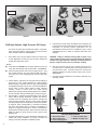
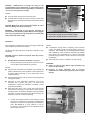
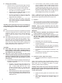
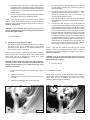
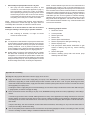
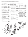
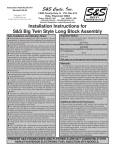
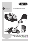
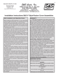
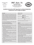
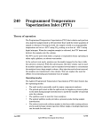
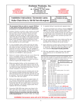
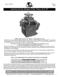
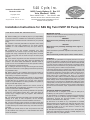
Instruction Sheet #51-1126
Revised 4-16-02
Copyright®, 2002
by S&S Cycle, Inc.
All rights reserved. Printed in the U.S.A.
S&S Cycle, Inc.
14025 County Highway G Box 215
Viola, Wisconsin 54664
Phone: 608-627-1497 • Fax: 608-627-1488
Technical Service Phone: 608-627-TECH (8324)
Technical Service Email: [email protected]
Website: www.sscycle.com
Installation Instructions for S&S Big Twin HVHP Oil Pump Kits
SAFE INSTALLATION AND OPERATION RULES:
● Before installing your new S&S oil pump it is your responsibility
to read and follow the installation and maintenance procedures in
these instructions and follow the basic rules below for your personal
safety.
● Gasoline is extremely flammable and explosive under certain
conditions and toxic when breathed. Do not smoke. Perform
installation in a well ventilated area away from open flames or
sparks.
● Compressed air and particles dislodged from using
compressed air are harmful to eyes and body. Wear protective
goggles when using compressed air and always direct air stream
away from body parts such as hands and eyes and other people
near you.
● Some solvents, degreasers and other chemicals are harmful to
skin, eyes and other body parts. Many items are flammable and
present a fire hazard. Read manufacturer's instruction label for
proper use. Use in well ventilated area and wear protective clothing
when using them to avoid personal injury.
● If motorcycle has been running, wait until engine and exhaust
pipes have cooled down to avoid getting burned before performing
any installation steps.
● Before performing any installation steps disconnect battery to
eliminate potential sparks and inadvertent engagement of starter
while working on electrical components.
● Read instructions thoroughly and carefully so all procedures
are completely understood before performing any installation steps.
Contact S&S with any questions you may have if any steps are
unclear or any abnormalities occur during installation or operation of
motorcycle with S&S oil pump on it.
● Consult an appropriate authorized H-D service manual for
correct disassembly and reassembly procedures for any parts that
need to be removed to facilitate installation.
● Use good judgment when performing installation and operating
motorcycle. Good judgment begins with a clear head. Don't let
alcohol, drugs or fatigue impair your judgment. Start installation
when you are fresh.
● For optimum performance and safety and to minimize potential
damage to oil pump or other components, use the mounting
hardware that is provided and follow all installation instructions.
●
Be sure all oil lines, supply and return, are routed correctly with
clamps in place and tightened. Lines must not contact exhaust pipes
or other extremely hot surfaces where they could melt or leak and
catch fire.
● Motorcycle exhaust fumes are toxic and poisonous and must
not be breathed. Run motorcycle in a well ventilated area where
fumes can dissipate.
IMPORTANT NOTICE:
Statements in this instruction sheet preceded by the following
words are of special significance:
WARNING
Means there is the possibility of injury to yourself or
others.
CAUTION
Means there is the possibility of damage to the engine or
motorcycle.
NOTE
Other information of particular importance has been placed in
italic type.
S&S recommends you take special notice of these items.
WARRANTY:
All S&S parts are guaranteed to the original purchaser to be free of
manufacturing defects in materials and workmanship for a period of
twelve (12) months from the date of purchase. Merchandise that fails
to conform to these conditions will be repaired or replaced at S&S's
option if the parts are returned to us by the purchaser within the 12
month warranty period or within 10 days thereafter.
In the event warranty service is required, the original purchaser must
call or write S&S immediately with the problem. Some problems can
be rectified by a telephone call and need no further course of action.
A part that is suspect of being defective must not be replaced by a
Dealer without prior authorization from S&S. If it is deemed
necessary for S&S to make an evaluation to determine whether the
part was defective, it must be packaged properly so as to not cause
further damage and be returned prepaid to S&S with a copy of the
original invoice of purchase and a detailed letter outlining the nature
of the problem, how the part was used and the circumstances at the
time of failure. If after an evaluation has been made by S&S and the
part was found to be defective, repair, replacement or refund will be
granted.
ADDITIONAL WARRANTY PROVISIONS:
(1) S&S shall have no obligation in the event an S&S part is
modified by any other person or organization.
(2) S&S shall have no obligation if an S&S part becomes defective
in whole or in part as a result of improper installation, improper
maintenance, improper use, abnormal operation or any other
misuse or mistreatment of the S&S part.
(3) S&S shall not be liable for any consequential or incidental
damages resulting from the failure of an S&S part, the breach of any
warranties, the failure to deliver, delay in delivery, delivery in nonconforming condition or for any other breach of contract or duty
between S&S and a customer.
(4) S&S parts are designed exclusively for use in Harley-Davidson
motorcycles. S&S shall have no warranty or liability obligation if an
S&S part is used in any other application.
1
1992-Later
HVHP
HVHP
1992-Later
Picture 1
S&S High Volume, High Pressure Oil Pumps
Picture 2
5.
The HVHP oil pumps were introduced by S&S in early 2002.
HVHP pumps are similar to previous ones in function but have
major machined differences. See Picture 1.
1.
Part number can be found on bottom surface of oil pump body.
In most applications a small mirror can be used to identify part
number with engine still in frame.
Instructions for HVHP pumps are different from instructions for
previous pumps. Refer to S&S Oil Pump Instructions 00-6251 for
information on previous pumps. (Instructions can be
downloaded at www.sscycle.com; call 608-627-1497 or e-mail
[email protected] if unable to download instructions from
Website.
CAUTION - Plating or otherwise altering S&S oil pump or any
component thereof may cause irreversible damage to pump and
interfere with engine lubrication. Damages caused by altered oil
pump or component will not be covered under warranty.
NOTES:
●
HVHP pump kits DO NOT use the same gaskets and only use
a few other internal parts used in previous kits. See Picture 2.
●
HVHP oil pumps provide 38% more oil supply volume. They
also increase pressure over 1992 and later OEM H-D pumps.
They offer 61% more scavenging than 1992 and later style
pumps.
6.
Both the "universal" pump cover 31-6079 and pump cover
31-6094 have the 1992-later style mounting bolt pattern and
feed and return holes. "Univeral" pump cover 31-6079 has
additional locations for feed and return holes at top of cover.
See Picture 3.
7.
Oil pump covers are described in more detail in "Oil pump cover
assembly" section.
2. Chrome Plating - S&S does not recommend chrome plating oil
pump body or cover. Proper preparation for plating requires
abrasive buffing compounds which can plug critical passages
and otherwise damage oil pump. Also, it is extremely difficult to
chrome plate oil pump without altering critical machined
surfaces. Chrome in these areas can impair pump's
performance by altering critical operating tolerances. In addition,
chrome may flake off and cause damage to pump and engine.
3.
4.
Powdercoating - Subjecting heat-treated alloys such as those
used in S&S oil pumps, crankcases, cylinders and heads to
excessive heat can drastically alter hardness, strength and
other important properties. Degree to which these properties
are altered depends upon temperatures reached and duration
of exposure. When powdercoating or otherwise processing
alloy parts, S&S exposes them to a maximum temperature of
370°F for no longer than 20 minutes. Under no circumstances
should parts be heated past 400°F. Owner assumes all risk and
liability for altering oil pump except to insure correct fit. See
following note.
Increased wall thickness of some aftermarket crankcases may
interfere with proper installation of oil pump. Procedure for
insuring correct fit is described in Installation section.
1
2
5
5
31-6079
4
31-6094
3
4
OIL HOLE IDENTIFICATION
1. Top oil return hole.
4. Lower oil return hole.
2. Top oil supply hole.
5. Middle oil supply hole.
3. Lower oil supply hole.
Picture 3
2
3
CAUTION - Bottom-mount oil supply line fitting is not
recommended for Dynas, Road Kings, or other models with oil
tank below transmission because of possibility of cavitation or
"air lock" occurring during oil changes.
1992-Later Case Machining
1
NOTES:
2
●
Only one supply and one return hole will be used.
●
#31-6302 and #31-6298 oil pump kits include oil pump drive
shaft gear, pinion shaft oil pump drive gear and breather gear kit
w/shims.
3
CAUTION -Metal filings, dirt and other foreign matter can cause
extensive damage to oil pump and engine.
WARNING - Compressed air and particles dislodged by
compressed air are potentially harmful. Wear protective goggles
when using compressed air and always direct air stream away
from yourself and others nearby.
1. Pressure relief valve vent hole.
2. Oil pressure passage to pinion shaft & crankpin.
3. Oil pressure passage to lifters and rocker arms.
Picture 4
Introduction
Read instructions completely and become thoroughly familiar with
entire installation procedure before starting.
NOTES:
●
If modification of pump body is necessary, remove minimum
amount of material required to properly position oil pump on
crankcase. Take special care not to damage gasket surfaces.
After modification, clean pump body thoroughly with suitable
parts cleaner and compressed air to remove metal filings
generated during procedure. Remove all traces of solvent prior
to installation.
●
S&S crankcases require no modification for S&S oil pump.
All S&S HVHP oil pump kits fit only crankcases machined for 1992later pumps.
CAUTION - Failure to perform all required steps may result in
engine damage.
A.
Disassembly and crankcase identification. All years.
1.
Remove old oil pump, loosen pushrods, remove cam cover,
cam and pinion shaft hardware from gearcase.
NOTES:
●
S&S has used 1991-earlier and 1992-later style mounting bolt
pattern in S&S Evolution style Long Blocks. Confirm pattern prior
to ordering HVHP pump body or cover. HVHP pumps fit only
1992-later patterns.
●
Oil pump gasket of known year can be used to positively identify
mounting bolt pattern.
●
Machining of some aftermarket crankcases may not be
consistent with a specific year group. If in doubt about
modifications required for aftermarket crankcase, contact
crankcase manufacturer.
●
S&S cases have either a two or three letter code stamped
above either the rear engine mount surface or above oil pump
mounting surface. The first letter designates oil pump year/style
machining. "A" means the case has 1991-earlier machining, "B"
indicates the case has 1992-later machining.
2.
CAUTIONS:
●
Failure to clean oil pump before engine assembly may
result in engine damage.
●
Improper oil pump installation due to incorrect
identification of crankcase year group may result in engine
damage.
Confirm that adequate clearance exists between new oil
pump body and crankcase by temporarily installing pump
assembly on crankcase and inspecting areas indicated in
photo. See Picture 5. In some instances it may be
necessary to remove small amount of material from pump
body to obtain correct fit.
Picture 5
3
B.
3.
Oil pump cover assembly.
1.
Universal oil pump cover #31-6079 has supply and return
holes at top of cover similar to 1991-earlier pump covers.
Cover #31-6094 plumbs the same as stock 1992-later.
Cover #31-6079 is often referred to as S&S "universal"
cover. It is supplied on S&S Long Blocks unless customer
specifies otherwise at time of order. Universal cover is
compatible with OEM rigid supply and return lines used on
1992-up models. Fittings for oil supply and return lines can
be placed in holes at either bottom or top of cover as
required by purchaser. Fitting for main oil supply line can
also be installed in hole in face of cover if desired.
a.
First step in cover assembly is to identify cover and
insure that cover is correct for application.
b.
Customer must then install oil line fittings and other
required hardware, if applicable, in cover.
c.
All covers require fittings for supply and return lines.
Cover #31-6079 offers more than one location for
supply and/or return line fittings.
NOTE - If OEM rigid oil lines are used, return fitting must face
forward, toward front of engine. Supply fitting will face downward at
approximate 45° angle toward lower left corner of pump cover.
d.
Customer must decide which holes in cover will be
used and block off holes not used with supplied pipe
plugs. Correct identification of locations for supply and
return fittings is critical.
C.
CAUTION - Incorrect placement of oil lines or oil line fittings can
cause extensive engine damage not covered under warranty.
See Appendix (Page 7) for correct routing of oil pump lines.
Inspection
S&S oil pump bodies, covers and gaskets may appear similar to
other manufacturer's products but should not be interchanged
due to possible differences that could impair oil pump function.
CAUTION - Using oil pump components other than those
provided by S&S may result in oil leak, insufficient oil pressure
and possible engine damage.
NOTES:
●
●
Covers #31-6079 and #31-6094 are compatible with rigid OEM
oil return and supply lines found on 1992-up models. In these
applications, hole #5 in face of cover is used for supply line.
Hole#4 in bottom left location is used for return line. (See
Picture 3.)
WARNINGS:
●
Many solvents are flammable and potentially toxic. Read
solvent manufacturer’s instructions prior to use.
●
Compressed air is potentially harmful, especially to eyes
and skin. Wear goggles and other protective clothing
during use, and direct air stream away from yourself and
others nearby.
After installing elbow fitting #50-8114 for return line, customer
must install compression fitting #50-8120 (supplied in kit) in
elbow rather than conventional hose fitting #50-8115. Fitting
#50-8115 will be used for supply line fitting. For use with OEM
rigid oil lines, return fitting must face forward, toward front of
engine. Supply fitting will face downward at approximate 45°
angle toward lower left corner of pump cover.
1.
Disassemble, clean, and inspect oil pump.
2.
Inspect gaskets for loose bits of material that could dislodge
and block oil passages.
3.
Lightly oil relief plunger, check ball, springs, and assemble
into their respective positions in the body, leaving check ball
cap loose for priming purposes in later steps.
4.
For installation of pump with engine on work bench. See
Step D.
5.
For installation of pump with engine in frame using existing
pump drive shaft. See Step E.
CAUTIONS:
●
●
Always apply Teflon tape or pipe sealant such as Loctite
PST to threads of fittings before assembling fittings or
installing fittings in cover. Failure to install fittings correctly
may damage cover and void warranty.
Apply tape or pipe sealant to threads only. Avoid using
excessive amounts that may protrude into and obstruct oil
passages or contaminate engine oil. Incorrect use of Teflon
tape or pipe sealant may cause engine damage not covered
under warranty.
2.
Cover #31-6079 - Fittings for oil supply and return lines can
be placed in holes at either bottom or top of cover according
to installer’s requirements.
a.
b.
4
Preparation - Apply Teflon tape or pipe sealant such as
Loctite PST to threads of fittings and elbows to be
used. If 1992-up OEM rigid return line is used,
substitute compression fitting for 1 hose fitting. Hole
#4 must be used for 1992-up OEM rigid return line.
(See Picture 3.)
Install hose fittings in elbows. Install compression fitting #508120 in return hole fitting #4 if 1992-up OEM rigid return line
is used. Compression fitting must face forward for use with
OEM rigid return line.
D.
Installation of pump. (Engine out of frame.)
1.
Assemble pump back into the configuration in which it was
received.
NOTE - A dab of Hylomar or other thin gasket sealer in corners of
gasket may be used to hold gasket in place if care is taken to avoid
critical areas such as oil passages and interior of oil pump.
Otherwise, gaskets should be installed dry.
CAUTION - Gasket sealant may interfere with engine lubrication
if allowed to enter oil pump or passages machined in crankcase.
Damage related to improper use of gasket sealant will not be
covered under warranty.
2.
Position pump body gasket onto crankcase with a dab of
sealer.
3.
Apply engine oil that is going to be used in the engine to oil
pump gears, driveshaft and driveshaft bushing in
crankcase.
4.
5.
Install oil pump in crankcase in normal fashion placing
pump drive gear over driveshaft as shaft is passed through
bushing and into crankcase gear compartment. Slide pump
assembly into place and install top two mounting bolts and
washers loosely.
5.
Push the driveshaft in toward the gearcase as far as it will
go while holding driveshaft gear in gearcase in place so
shaft goes through it.
6.
Install pump body assembly onto the driveshaft, turn return
idler gear as needed to get return gear teeth to
mesh,
slide pump assembly into place and install top two
mounting bolts and washers loosely.
7.
Now push driveshaft from gear case end back as far as it
will go towards the transmission, rotating shaft so keyway is
accessible..
8.
Install the feed side drive gear onto the driveshaft with
counterbore facing the transmission. Slide gear all the way
in until it bottoms in the gear pocket. This will leave the drive
shaft protruding from the gear with the keyway and snap ring
groove exposed. Install the feed gear key. This key is smaller
than the standard oil pump drive keys used on previous S&S
oil pumps. Tweezers or small needle nose pliers will make
for easier key installation. After the key is installed, install the
"c" shaped retaining ring into the ring groove. Now push the
driveshaft forward towards the gear case making sure it
passes through the driveshaft gear in the gearcase. Turn
pump to align keyway in shaft and drive gear. Install the
driveshaft key and snap ring inside the gearcase.
Turn pump to align keyway in shaft and drive gear. Install the
driveshaft key and snap ring inside the gearcase.
NOTE - Insure that drive shaft key and snap ring are installed
properly. If snap ring is installed incorrectly, sprung or otherwise
damaged, it may become dislodged or allow gear key to come out.
Picture 6 and Picture 7.
CAUTION - Loss of oil pump drive gear snap ring or key will
result in disengagement of oil pump causing loss of oil pressure
and possible engine damage.
6.
E.
Proceed to Step F.
Installation of pump. (Engine in frame.)
With engine in frame, the pump driveshaft cannot be removed.
The HVHP pump can be installed without removing the
driveshaft from the crankcases. The existing driveshaft in the
cases will work with the HVHP pump.
NOTE - A dab of Hylomar or other thin gasket sealer in corners of
gasket may be used to hold gasket in place if care is taken to avoid
critical areas such as oil passages and interior of oil pump.
Otherwise, gaskets should be installed dry.
NOTE - Insure that drive shaft key and snap ring are installed
properly. If snap ring is installed incorrectly, sprung or otherwise
damaged, it may become dislodged or allow gear key to come out.
Picture 6 and Picture 7.
CAUTION - Loss of oil pump drive gear snap ring or key will
result in disengagement of oil pump causing loss of oil pressure
and possible engine damage.
CAUTION - Gasket sealant may interfere with engine lubrication
if allowed to enter oil pump or passages machined in crankcase.
Damage related to improper use of gasket sealant will not be
covered under warranty.
9.
Proceed to Step F.
1.
Position pump body gasket onto crankcase with a dab of
sealer.
F.
2.
Prelube the return gears.
3.
Install the return side key and drive gear onto the pump
drive shaft.
4.
Install the return side idler gear into the pump body.
NOTE - A dab of Hylomar or other thin gasket sealer in corners of
gasket may be used to hold gasket in place if care is taken to avoid
critical areas such as oil passages and interior of oil pump.
Otherwise, gaskets should be installed dry.
Installation of cover.
Correct
Picture 6
Incorrect
Picture 7
5
2.
CAUTION - Gasket sealant may interfere with engine lubrication
if allowed to enter oil pump or passages machined in crankcase.
Damage related to improper use of gasket sealant will not be
covered under warranty.
1.
Position pump cover gasket onto pump body with a dab of
sealer.
2.
Install the two inboard mounting bolts with washers through
the pump cover gasket and pump body, and start by a
thread or two.
3.
Install the pump cover, two outboard bolts with washers, but
do not tighten at this time.
4.
Perform the free spin procedure.
a.
b.
G. Priming the oil pump.
Priming the oil pump will generally fall into one of three
catagories:
Engine on bench.
Connect oil lines as required. (See Appendix on oil line
routing if necessary.) Fill oil tank.
b.
Remove cap, spring, and check ball from oil pump.
c.
Rotate pump drive shaft gear (top of gear is moved
towards right side of engine) untill air-free oil can be
seen exiting from check ball cavity.
When pump is primed, replace check ball, spring, and
cap.
NOTE - This procedure can be performed even if engine is fully
assembled. Pump rotation will be achieved by removing spark plugs
and cranking engine over with kick or electric starter.
3.
Engine in frame.
Oil tank below the oil pump.
a.
Connect oil lines as required. (See Appendix on oil line
routing if necessary.) Fill oil tank.
b.
Remove cap, spring, and check ball from oil pump.
c.
Fill check ball cavity with oil and observe the rate at
which it drains away. Re-fill cavity as necessary until
the slowest drain down rate is achieved.
d.
When drain down rate has stablized, fill check ball
cavity one last time, then install check ball, spring, and
cap.
NOTE - This procedure can be performed on assembled engine if oil
pump happens to lose prime after an oil change.
CAUTION: - "Air lock" or cavitation can occur if trapped air is
not released from oil pump after installation. It can occur with
new pump as well as used pump that has been removed from
engine, and interferes with oil circulation. It is installer's
responsibility to remove trapped air by priming pump prior to
running engine and to confirm correct pump operation with
engine running.
H.
Assemble gearcase.
The engine is to be delivered to a customer or installed at a
later date. Priming the pump on the bench will minimize the
time spent priming the pump after engine is installed.
Install the previously removed pinion shaft components
according to the standard procedure for the appropriate
year group. Year groups applicable to the pinion shaft
components are as follows:
a.
Remove cap, spring, and check ball from oil pump.
a.
1990-'92 OEM Harley-Davidson
b.
Attach a piece of clear tubing approximately 12" long to
the supply fitting on pump cover. Hold tubing vertically
and fill with same type of oil to be used in engine.
b.
1993-'99 OEM Harley-Davidson
c.
All S&S Big Twin with 1992-up style crankcase.
c.
Using thumb, rotate pump drive shaft gear in normal
direction of rotation. (Top of gear is moved towards
right side of engine.)
d.
Rotate shaft (refilling tubing as necessary) until no air
bubbles can be seen in the oil exiting the check ball
cavity.
e.
6
a.
d.
Evenly tighten two remaining bolts to 90-110 in-lbs. If
remaining bolts are inaccessible with torque wrench
due to oil line fittings, temporarily remove fittings or
carefully tighten bolts with thin box-end wrench.
CAUTION - Failure to correct bind may result in damage to oil
pump or other engine parts.
1.
Oil tank above the oil pump.
While continually turning oil pump drive gear in
gearcase to check pump for binding, gradually tighten
cover bolts in an X-pattern to a final torque of 90-120
in-lbs, leaving the top two pump body bolts loose. If
pump binds, loosen cover screws and shift pump
slightly while rotating gears. Retighten cover bolts
while turning driveshaft to confirm bind- free pump
operation. Pump should operate smoothly when
correctly aligned on crankcase.
NOTE - Oil pump failure may result if an attempt to bypass the "free
spin" procedure is made. The pump can be changed if you do not
remove the pinion shaft hardware but you cannot check for pump free
spin. If this procedure is not performed, pump failure may result and
the part will no longer be covered under warranty.
Engine in frame.
When pump is primed, re-install the check ball, spring,
and cap. Place protective cap over supply fitting.
1.
NOTE - S&S supplies only the 1954-'89 style pinion shaft oil pump
drive gear in its production V2 Big Twins. This gear must be installed
with the chamfer towards the shoulder on pinion shaft.
CAUTION - Installing pinion shaft oil pump drive gear
backwards on pinion shaft may cause stress riser resulting in
eventual failure of shaft. Damage caused by incorrect
installation of gear or other parts is not covered under warranty.
I.
Initial startup and post-operation checks. All years.
1.
After pump has been installed and primed, oil lines
connected in correct manner (See Appendix on page 7.)
and oil tank filled to correct level, confirm oil circulation
with oil pressure gauge and by removing cap from oil tank
and observing oil return to tank. If oil is not seen returning
to tank, S&S recommends removing return line from tank
and placing end in drain pan to confirm oil circulation.
NOTE - Engine oil circulates under pressure. Areas exposed to
escaping oil should be covered with rags and engine turned off
immediately after oil circulation is confirmed to minimize oil loss.
WARNING - Oil on tires or brakes can cause loss of control of
motorcycle resulting in serious injury to operator and others.
2.
NOTE - All S&S 1992-later style cases and most 1992-earlier H-D
crankcases have provision in rear of cam-side crankcase for two
pipe-thread fittings. Fitting above the oil pump is for vent line from oil
tank. The bottom hole is used as crankcase breather on 1992-earlier
models and on S&S Long Blocks set up for crankcase breathing or
combination crankcase-cylinder head breathing. Engine must have
1992-earlier style cam cover and gasket for crankcase breathing;
otherwise, large oil losses will occur out the bottom hole. The vent
fitting will be used in all applications. The bottom hole will be used in
most "crankcase breather" situtations. Any crankcase breather hole
not used must be blocked.
J.
After confirming oil circulation, run engine for several
minutes and check for leaks.
NOTES:
●
Low oil pressure is often blamed on oil pump when actual cause
is worn bushings or another internal component. A new oil pump
will not correct problems caused by worn parts and excessive
operating clearances. If low oil pressure exists after new oil
pump is installed, check clearances and other possible causes
such as installation of different gear cover, tappet guides, etc.
●
Sudden clatter in previously quiet hydraulic lifter may indicate
lifter failure OR excessively low oil pressure and should be
investigated. It is not unusual for hydraulic lifters to clatter when
a new or recently rebuilt engine is first started, but noise should
disappear as lifters pump up. Time required depends on several
factors including brand of lifter, oil viscosity and temperature.
Removing pump for service.
1. Disconnect oil lines
2. Loosen pushrods
3. Remove gear cover
4. Remove cam
5. Remove pinion shaft hardware
6. Remove oil pump drive shaft gear retaining ring
7. Remove oil pump cover
8. Push pump drive shaft towards transmission to gain
access to retaining ring and key, remove retaining
ring/key.
9. Remove feed gears
10. Remove remaining pump bolts and remove pump
assembly from drive shaft
Appendix: Oil Line Routing
Most Big Twin oiling systems utilize three oil circuits: supply, return and vent.
●
Supply circuit delivers oil from tank to supply fitting of oil pump cover. See Picture 3. In motorcycles with oil tank located above
transmission, supply fitting in oil tank is almost always located on bottom of tank at center or rear. In Dynas, Road Kings, and other
models with oil tank below transmission, supply line exits oil tank on bottom of primary drive side, then crosses to cam side and connects
with supply fitting on oil pump cover.
To distinguish oil tank ’s supply fitting from vent and return fittings, remove oil lines and pour small amount of oil into tank. With motorcycle
in upright position, oil will flow out supply line fitting.
●
Return circuit delivers oil from return fitting in oil pump cover, see Picture 3, through oil filter and cooler (if applicable), to return fitting in
oil tank.
In horseshoe-type oil tanks used on Softails, OEM rigid frames and many custom applications, two fittings nearest front of oil tank are
identical. Fittings may enter through upper area of tank or connect to fittings near bottom that are attached to standpipes inside tank.
These fittings are for oil return and vent lines and in most cases may be used interchangeably. Main exception is with oil tanks with "in
tank" oil filter.
In Dynas, Road Kings, and other models with oil tank located below transmission, return fitting is on top of oil tank nearest center of
motorcycle. Vent fitting is beside return fitting.
●
Vent circuit equalizes pressure between oil tank and crankcase. See preceding paragraph for location of vent fitting in oil tank. Vent line
runs from vent fitting on oil tank to fitting in crankcase located above the oil pump.
7
Replacement Parts for S&S High Volume, High Pressure Oil Pumps
1. Pump body assembly
Fits 1992-'99 V 2 ...................31-6078
19. Fitting, supply/return hose
(HD#63533-41) .........................50-8115
2. Shaft, idler ...........................31-6080
20. Return fitting, compression
(HD#63523-92) ........................50-8120
3. Seal, drive shaft .................31-6064
21. Seal, tubing 3⁄8" x 1⁄2" OD x 1⁄4" Viton
.............................................50-8271
4. Gear, return drive, HVHP .. 31-6075
5. Gear, return idler, HVHP.... 31-6083
22. Screws, mounting (SHCS)
1
⁄4"-20 x 21⁄2" (10 Pack) ..........50-0212
6. Gear, supply drive, HVHP . 31-6074
7. Gear. supply idler, HVHP....31-6081
⁄4"-20 x 11⁄2"
(10 Pack) ..........50-0224
1
29. Shim, steel breather
.100" ..................................33-4200
.110" (HD#25320-79) ..............33-4201
.120" (HD#25322-79) ..............33-4202
.130" (HD#25325-79) ..............33-4203
.140" (HD#25327-79) ..............33-4204
.150" ..................................33-4205
.160" ..................................33-4206
.170" ..................................33-4207
(10 Pack) ...........50-7013
30. Gasket, pump body 1992-'99 HVHP
(10 Pack) ................................31-6090
10. Plug, 1⁄8"-27 (HD#45830-48).....50-8331
24. Retaining ring (HD#26348-36)
(10 Pack) ................................50-8106
31. Gasket, pump cover 1992-'99
HVHP (10 Pack) .....................31-6091
11. Ball, check valve (HD#8866 & 8873)
.............................................50-8091
25. Retaining ring, external (HD#11002)
(10 Pack) ................................50-8107
32. Gasket rebuild kit (Not shown.)
Includes key and retaining ring.
12. Spring, check valve (HD#26262-80)
(10 Pack) ................................31-6092
26. Gear, pump drive, 24T (HD#26345-73)
.............................................33-4230
13. Relief valve..........................31-6082
27. Gear, pinion shaft pump drive 1954-'89
14. Spring, relief valve (HD#26207-83)
(10 Pack) ................................31-6084
(HD#26349-73, #26349-73A, 26349-84)
8. Shaft, drive (HD#26346-70) ......31-6011
23. Washer, ⁄4"
1
9. Key, drive shaft....................50-8228
.............................................33-4232
28. Gear, steel breather valve
15. Screw, check valve & relief valve
cover (HD#26263-80)...............31-6021
1992-'99 BT HVHP .............31-6299
33. Master rebuild kit (Not shown.)
Includes gasket rebuild kit, seal,
retaining ring, relief valve spring,
check valve spring, check valve,
ball, and cover screw o-rings.
1992-'99 BT HVHP .............31-6300
1977-up Standard size
Gear only .........................33-4241
Gear and shims ...............33-4259
16. O-ring (HD#11105 )
(10 Pack) ................................50-8078
1977-up +.030" oversize
Gear only .........................33-4242
Gear and shims ...............33-4260
17. Pump cover assembly, 1992-'99
Universal .............................31-6079
Standard (N/S) ....................31-6094
18. Elbow, supply/return (HD#26338-68)
.............................................50-8114
27
25
26
18
31
15
28
29
16
19
16
10
19
9
14
10
12
13
17
23
22
10
8
23
3
19
18
22
10
20
21
6
1
2
24
8
30
11
19
18
4
7
5