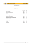
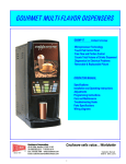
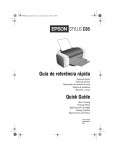
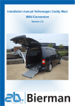
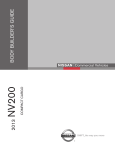
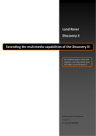
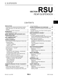
1
Lotus Service Notes
Section BR
BODY FITTINGS
SECTION BR
Sub-Section Page
Removable Roof
BR.1
2
Rear Window Shroud (Elise only)
BR.2
6
Front Body Access Panels
BR.3
7
Engine Cover Lid
BR.4
7
Door Hinge Cover Panel
BR.5
9
Front Clamshell
BR.6
9
Rear Clamshell
BR.7
11
Door Mirrors
BR.8
13
Door Beam & Hinge
BR.9
14
Door Shell Assembly
BR.10
16
Door Glass, Guide Rails & Winder Mechanism
BR.11
17
Electric Windows
BR.12
21
Door Seals
BR.13
23
Door Latch Mechanism (without CDL)
BR.14
24
Central Door Locking
BR.15
27
Instrument Binnacle & Dash Panel
BR.16
28
Windscreen
BR.17
33
Page 1
Lotus Service Notes
Section BR
BR.1 - REMOVABLE ROOF
The Lotus Elise has been designed to exploit the pleasures of open top motoring, the better to enjoy
exposure to the natural environment, unencumbered by the restrictions and confinement bestowed by a cockpit roof. In order to provide some weather protection to the occupants and vehicle interior, and allow the
continued enjoyment of the car in unfavourable weather conditions, a simple hard or soft top roof may be fitted.
Due to the constantly changing dynamic and wind pressure loadings to which the roof structure is subject
when driving, and the tolerances required to allow for repeated removal and refitting of the roof, complete
weather sealing of the roof cannot be guaranteed, such that some wind noise and minor water leaks are
considered normal for this model. The Elise or Exige should not be subjected to an automatic car wash. Such
machines can induce water leaks caused by high pressure water jets which are not representative of conditions
encountered during normal use. The brushes used may also damage the fabric of the soft top roof.
Exige Hardtop Roof:
The Lotus Exige has been conceived and configured as a sports coupé with a removable roof. The
aerodynamic performance of the bodyshell including the front spoiler, rear aerofoil, roof panel and tailgate
have been tuned to provide the optimum handling balance with the roof panel also contributing to the flow of
cooling air into the top of the engine bay.
The roof panel may be removed for better access to the interior for servicing, and the car may be driven
without the roof fitted, but wind buffeting and increased noise levels will be experienced. In order to avoid
discomfort, and so as not to compromise engine cooling efficiency, it is recommended to restrict usage in this
configuration to lower vehicle speeds.
Soft Top Roof
A hollow composite roof siderail is used on each side of the car to bridge each top corner of the windscreen frame to the roll over bar, and provide a mounting for a weatherstip seal, against which the top edge of
the door glass abuts. The soft top roof canopy is fixed to each siderail, which uses a spigot pin at the front and
rear to engage with a slot in a latch plate on the header rail and roll over bar. A second, spring loaded spigot pin
at each end of the siderails, is arranged to slide into a ramped hole on the latch plates and secure and tension
the soft top via steel cables running through the front and rear of the roof canopy.
Soft Top - Fitting
WARNING: The soft top roof should be fitted only whilst the vehicle is safely parked.
1.
2.
3.
From its stowage bag in the rear luggage
compartment, withdraw the roof assembly
and support stays. Lower both door windows, or open both doors.
Insert the two, identical, roof support stays,
with the arrows pointing forwards, into the
slots above the rear window, and in the windscreen header rail. Note that the slots are
keyed to prevent the stays being fitted the
wrong way round.
Lay the soft top roof across the centre of
the roof space with the arrows on the side
rails pointing forwards.
Page 2
FITTING ROOF STAYS
Arrows
point forward
Rear end keyway
b332
Lotus Service Notes
4.
5.
6.
Section BR
Roll out the left hand side of the roof, and
engage the fixed spigot pin on the front and
rear end of the rail, into the uppermost slot
in the latch blocks at the front and rear of
the roof aperture.
Ensure that the tensioning cables at the front
and rear edges of the roof canopy are correctly located in the channels between the
seal and body before rotating the left hand
side rail downwards.
Ensure that both spring loaded pins ‘click’
into their ramped slots indicating that latching is complete. If necessary, ease the latch
handles on the inside face of the side rails
inwards to facilitate latching. Pull up on the
side rail to check security.
Spigot
pin
Spring
loaded
pin
FITTING SIDERAIL
ohs111
On the right hand side of the car, repeat steps (4) and (5) for the second side rail, noting that greater
rotating force will be required as tension is applied to the canopy.
Note: Engaging the left hand roof side rail first, will minimise the possibility of the canopy tensioning
cable adjusters causing damage to the roof seals.
Soft Top - Removal
WARNING: The soft top roof should be removed only whilst the vehicle is safely parked.
1.
Open both doors or lower both door windows.
2.
On the inside face of the right hand roof
side rail, locate the two latch release levers:
Pull the two lever handles towards each
other to release the side rail latches (press
down on the side rail if necessary to relieve
the load on the latch pins), and rotate the
rail upwards to release the canopy tension.
3.
Repeat step (2) for the left hand side rail.
Note: Releasing the right hand roof side
rail first, will minimise the possibility of the
canopy tensioning cable adjusters causing
damage to the roof seals.
RELEASING ROOF SIDE RAIL
ohs112
4.
Carefully roll up each side of the roof canopy towards the centre, lift off the car, and stow in the roof bag.
5.
Unhook the two roof stays and stow in the roof bag.
Important Note: If the roof is not fully dry, it should be stowed for no longer than a few days before unrolling
or refitting and allowing to air dry completely. Prolonged stowage of a wet or damp roof will promote rotting of
the fabric.
Roof Cable - Front: The tension of the steel cable running through the front edge of the roof canopy should be
adjusted with the side rails latched. Hook a spring balance under the centre of the cable, and apply an upwards
force of 6 kgf. Adjust the cable tension to achieve a vertical gap of 6mm between the cable and top surface of
the windscreen surround.
Page 3
Lotus Service Notes
Section BR
Roof Cable - Rear: The roof rear cable tension should be sufficient only to maintain stability of the roof canopy
shape.
Side Rail Front Latch Plates: The latch plates on the windscreen header rail are secured using a two part
adhesive. If necessary, use Betaclean 3900 (A100B6008V), Betaprime 5404 (A082B6337V), and a 50/50 mix
of two part adhesive Betamate 7064S (A116B0159V) and Betamate 7014 (A116B0158V) to refix.
Hard Top Roof (Parts List 12.04)
Note
The hard top roof has been designed to provide a seasonal, rather than single trip option. Some owners
may prefer to entrust the fitting and removal of the hard top roof to their dealer.
When stowing the roof off the car, care should be taken to avoid damage to the roof corners; e.g. use a
suitable soft floor covering on which to stand the roof.
Fitment or removal of the hardtop is made considerably easier with the assistance of a second person.
Use only the ‘Torx’ tool supplied in the vehicle tool kit to tighten or release the roof fixing screws.
The hardtop roof fixings are made captive to the roof to prevent their loss.
Hard Top - Fitting
WARNING: The hard top roof should be fitted only whilst the vehicle is safely parked.
1.
Open both doors, and preferably with the
aid of an assistant, lower the roof onto the car
holding aside the loose tethered fixings to avoid
their entrapment or their causing paint damage.
Position the rear edge of the roof first before locating the front edge against the windscreen
header rail.
2.
Locate a front spigot bracket into its latch
plate lower slot (lifting the roof slightly to allow
this) and retain to the roof with the Torx bolt. Use
only the special tool supplied, and do not fully
tighten at this stage.
FRONT
SPIGOT
BRACKET
3.
Repeat step (2) for the opposite front spigot
bracket.
4.
Engage a rear cup bracket with the lower
tongue on its rear latch plate, and retain to the
roof with the Torx bolt. Use only the special tool
supplied, and do not fully tighten at this stage.
Ensure that the cup is fully located onto the
tongue.
5.
Repeat step (4) for the opposite rear cup
bracket.
FITTING REAR CUP BRACKET
6.
Push the roof fully forwards before tightening the front spigot brackets using only the special tool supplied. Hold each rear cup bracket in
alignment whilst tightening the single fixing screw
for each bracket. Do not overtighten.
7.
Fit the cover panels to each rear corner of
the roof, noting that the panels are handed for
left and right sides. Press the panels firmly into
position fully to engage the 'Velcro' fixing patches.
Page 4
REAR CORNER
COVER PANEL
b330
Lotus Service Notes
Section BR
8.
Using the special tool provided, install the
windscreen header cover panel by locating first
with the central screw, and then by the outer
screws before tightening in the same order.
9.
Check that the roof is secure by pulling upwards on each corner in turn. If any upward movement is evident, check the correct fitment of all
mounting brackets.
WINDSCREEN
HEADER TRIM
Hard Top - Removal
WARNING: The hard top roof should be removed only whilst the vehicle is safely parked.
1.
WINDSCREEN
HEADER TRIM
b331
Open both doors.
2.
Using the special tool supplied, release the
three Torx screws securing the windscreen header
trim panel, and remove the panel.
3.
Using the special tool supplied, slacken the
Torx screw securing each front corner spigot
bracket to the roof, but do not yet remove the
screws.
FRONT CORNER
SPIGOT BRACKET
b330
4.
Pull off the trim cover from each rear corner of the roof panel and remove the screw securing the hook bracket to the latch plate at each
rear corner.
REAR CUP BRACKET
5.
Remove the two front corner bracket fixing
screws and lift the front edge of the roof slightly
to release the front brackets from their latch plate
slots.
6.
With the aid of an assistant, lift the roof from
the car taking care to restrain the tethered brackets to avoid damaging the paintwork.
7.
If storing the roof vertically, take care to avoid damaging the panel corners by using a protective floor
covering.
Page 5
Lotus Service Notes
Section BR
BR.2 - REAR WINDOW SHROUD (Elise only) (Parts List 10.20)
The rear window shroud is a body colour composite panel which covers the seat belt mounting frame/roof
hoop, and forms a capping for the rear of the cockpit. The panel is secured by two brackets on its front edge
which are fixed each side by a single M6 screw to the top of the rear bulkhead panel and which are accessible
from within the cabin. On some cars it may be necessary first to remove a trim panel secured by five screws.
Note that Neoprene washers are used between the brackets and the bulhead.
Each rear leg of the shroud is fitted with a captive M6 stud, which locates through a hole in the clamshell
buttress, with the retaining nut accessible either from the engine bay, or wheelarch area. A foam gasket is used
to prevent chafing damage between the shroud and clamshell.
When removing the shroud, it is also necessary to peel off the rear weatherstrip from the front edge of the
panel, and to remove the two cant rail latch plates from their brackets on the roof hoop.
Note that on the Exige, the rear window shroud is an integral part of the rear clamshell moulding.
Roof/'B' post
weatherstip seal
Neoprene
washers
Fixing screw to
rear bulkhead
Fixing nut to
rear clamshell
Rear window shroud
Foam gasket
pl1020mt
Page 6
Lotus Service Notes
Section BR
BR.3 - FRONT BODY ACCESS PANELS
(Parts List 10.09a)
Elise
Two removeable, body colour composite panels are provided in the front body to
allow access to the front fusebox and brake
fluid reservoir.
To remove an access panel: Use the hexagonal key supplied in the vehicle tool kit (in the
battery cover rear pocket), to release the single threaded fastener securing the outboard
corner of the panel, and withdraw the panel
REMOVING ACCESS PANEL
from the two locating holes in the front body
spine. Guard against the lightweight panel
being blown away and damaged by a strong
wind.
To refit a panel: Hook the extended lip on the front edge of the panel beneath the rear edge of the louvre panel
before engaging the two locating pegs on the inboard side of the access panel with the grommeted holes in the
front body spine. Fit the single screw at the outboard corner of the panel into the captive nut in the body, taking
care not to cross-thread or overtighten the screw. Re-stow the hexagonal key in the tool kit.
Note that the outboard fastener uses a mounting plinth adjustable in height to allow optimum panel
alignment to be achieved.
ohs93
WARNING: Ensure the access panels are refitted and properly secured before driving.
Exige
The access panels on the Exige model are shorter front to back than those of the Elise, and are retained
by three socket head screws, the outermost of which features an adjustable plinth to allow panel height adjustment.
BR.4 - ENGINE COVER LID (Parts List 10.11)
Elise
The engine cover/boot lid is moulded from glass fibre composite and incorporates 4 engine cooling outlet
grilles secured by double sided tape and plastic rivets into recessed apertures. Two hinges are used to attach
the lid to the rear bulkhead, with stud plates fixing the hinges to the bulkhead from the engine bay side, and the
nuts accessible from the cabin after removal of the rear bulkhead trim panel. A single, key operated latch
mechanism secures the lid to a striker pin mounted on the clamshell engine/boot bulkhead. The latch is
released by inserting the ignition key into the lock and turning clockwise, the lock barrel being connected to the
latch mechanism by a short link rod. When the latch is released, a spring plunger will lift the lid sufficiently to
allow it to be raised fully by hand. Support the lid by inserting the prop provided on the boot bulkhead into the
slotted plate adjacent to the latch mechanism. The spring plunger also operates a micro-switch for the alarm
system, and is protected from exhaust manifold heat by a steel shield.
When closing the lid, fully engage the latch mechanism by pressing down on the cover only immediately
above the latch. Note that the lock mechanism plastic cover plate on the underside of the engine lid, serves
also to channel any water ingress from around the lock into the engine bay. Drain holes are provided in the
gutter surrounding the engine bay, with a collector and drain tube fitted at the rearmost extremity.
On USA models, an fluorescent emergency internal release handle is fitted on the underside of the lid to
facilitate the escape of a trapped child.
To remove the engine cover, release the cover from the two identical hinges. Note that the hinges also
serve to clamp the clamshell front edge to the cabin rear bulkhead.
Beware that the engine cover is locked whenever it is closed, and always requires the use of the ignition
key to release. Owners should be made aware of the importance of having a spare key available in case of
inadvertently locking the keys in the boot.
Page 7
Lotus Service Notes
Section BR
Theaded insert
in engine lid
Engine lid hinge
Studplate clamping hinge &
clamshell to bulkhead
b318
Nut inside cabin
Exige
On Exige models, the double skin, moulded composite tailgate panel, mates with an air intake duct in the
clamshell and roof panel to admit cooling air into the engine bay, and also features seven steel mesh grilles to
allow for the exhaustion of hot air. The tailgate panel uses extruded alloy hinges at its front edge, anchored to
the underside of the clamshell, and is provided with a gas spring strut to support the lid in the fully open
position. The latch mechanism is mounted on the boot bulkhead, where it, and an adjacent alarm plunger
switch are protected by a steel heat shield. The latch is operated by a cable release from a lever handle
mounted outboard of the driver's seat back.
A rear aerofoil with integrally moulded support struts, is secured to the rear end of the tailgate and
transfers loads via adjustable abutments into the boot bulkhead and body structure.
Tailgate release handle
ohs141
Page 8
Lotus Service Notes
Section BR
BR.5 - DOOR HINGE COVER PANEL (Parts List 10.01)
A separate glass fibre composite body panel is used to fill the area beween the door and wheelarch, and
uses threaded fasteners to attach to the rear of the clamshell, top of the sill and bottom inboard edge of the sill
panel.
To remove a door hinge cover panel:
From beneath the sill, remove the two fixings securing the bottom edge of the hinge panel to the sill.
Remove the filler panel concealing the fixing securing the hinge cover to the door sill recess, and remove
the fixing.
Remove the wheelarch liner and remove the single screw securing the door hinge cover panel to the
clamshell.
Release the repeater lamp harness and withdraw the panel.
No fixing used
in this position
Remove front
top fixing
Door
sill
filler
panel
Door hinge
cover panel
Hinge cover to
door sill fixing
Hinge cover to
sill underside
b231
BR.6 - FRONT CLAMSHELL (Parts List: Elise 10.01; Exige 10.01x)
The front clamshell is a bonded assembly of several glass fibre composite mouldings incorporating both
front wings, the front access aperture, radiator air intake and headlamp housings. The clamshell is secured to
the windscreen frame, radiator mounting panel and other panels using threaded fasteners for ease of removal
and to facilitate service access and body repair.
To Remove Front Clamshell
1.
Remove both front body access panels.
2.
Remove both front wheelarch liners;
Page 9
Lotus Service Notes
Fixing inside
headlamp
housing
Section BR
Clamshell spine to
wiper motor bracket
Clamshell lower front
edge to undertray
Fixing to
windscreen
frame
Fixing to base of
windscreen pillar
Fixing to radiator mounting panel
(not used with oil coolers)
Fixing of door hinge
cover panel to clamshell
b316
3.
From inside each wheelarch, remove the single screw securing the top edge of the door hinge cover
panel to the clamshell. On cars fitted with front mounted oil coolers, release the hoses from any clamshell
clips around the top of the wheelarch.
4.
Via each door aperture, remove the single fixing securing a bracket at the top rear corner of the clamshell
to the base of the windscreen pillar.
5.
Remove the fixing at each side securing the clamshell to the bottom of the windscreen frame.
6.
Elise: Remove the two nuts securing the clamshell spine bracket to the wiper motor bracket extension.
Exige: Remove the two nuts and bolts securing the clamshell spine to the wiper motor extension bracket,
and the two screws each side securing the clamshell channel to the radiator air deflector panel.
7.
If fitted, remove the single fixing at the bottom front of each wheelarch, securing the clamshell to the
radiator panel extension (not used on oil cooler cars).
8.
Remove the headlamp cover/mask assembly from each side by releasing the three socket head screws
inside the wheelarch. Remove the clamshell fixing at the front of each headlamp housing. Release the
headlamp harnesses, and feed through the clamshell hole. Disconnect the aerial lead(s).
9.
Beneath the nose, release the screws fixing the front lower edge of the clamshell to the alloy undertray.
10.
Lift the clamshell from the car. Note any spacing washers or shims fitted at any fixing point.
Page 10
Lotus Service Notes
Section BR
BR.7 - REAR CLAMSHELL (Parts List: Elise 10.01; Exige 10.01x)
The rear clamshell is a one piece composite moulding incorporating both rear wings, the engine bay
aperture, rear transom and integral luggage bay. The clamshell is secured to the chassis and other body
panels by threaded fasteners for ease of service access and body repair.
To Remove Rear Clamshell
1.
Remove the soft or hard top roof (including Exige) - see sub-section BR.1
2.
Remove both rear wheelarch liners;
3.
Elise: Remove the rear window shroud - see sub-section BR.2.
Exige: From within the cabin, remove the two screws above the rear window securing the top edge of the
clamshell to the rear bulkhead. Remove the two cant rail latch plates from their brackets on the roof
hoop. Peel off the weatherstrip seal from the clamshell flange.
Boot floor to subframe
Engine lid hinge
fixings
b317a
Fixings to sill
panel and grille
'B' post fixing
from inside
cabin
4.
From inside the cabin, remove both seats and the full width trim panel from the rear bulkhead. From the
access thus provided, remove the fixing securing the front end of the clamshell to the 'B' post above the
engine bay air intake.
5.
Elise: From inside the cabin, release the fixings securing the engine lid hinges to the rear bulkhead, and
withdraw the engine lid complete with hinges.
Page 11
Lotus Service Notes
Section BR
6.
Release the six (USA market) or eight (other cars) screws securing the fuel filler neck to the clamshell.
Withdraw the filler neck from the clamshell aperture, noting the earth braid secured to the roof hoop
backstay. Keep the filler cap fitted to minimise vapour hazard.
7.
Remove the air filter box intake scroll, and from inside each rear wheelarch, release the air intake grille
fixings, and the two screws securing the clamshell to the waistline joint of the sill panel. Withdraw each
grille from its retaining clip.
8.
Remove the battery and feed the battery cables through the clamshell grommet. Disconnect the rear
harness and rear lid switch harness from the area behind the battery, and feed through the clamshell
grommet.
9.
Remove the rear diffuser panel.
10.
From inside the luggage area, release the two screws each side securing the boot floor to the subframe.
11.
Unhook the washer bottle.
12.
Withdraw the clamshell from the car, noting any spacer pads fitted on the subframe.
13.
Refit in reverse order to disassembly with the following notes:
Shimming of clamshell floor mounting points:
It is most important to maintain a gap of at least 7mm between the phenolic resin heatshield rivetted to
the underside of the clamshell boot floor, and the exhaust muffler corrugated heat shield bolted to the subframe. The corrugated shield must touch neither the muffler, nor the clamshell mounted shield, or heat damage may be caused to the clamshell.
On factory build, the subframe is marked adjacent to each of the four clamshell mounting points with the
shim thickness required. Shim plates are available in 1mm and 2mm thicknesses. If a new subframe is being
fitted, or the markings are not visible;
Use a straight edge across the clamshell rear mounting points on the subframe, and measure down to the
muffler heatshield. Sufficient shims need to be used to bring this dimension to a minimum of 7mm.
With these shimplates fitted, trial fit the clamshell and if necessary add further shims to optimise the fit of
the clamshell with respect to sill and door shutlines.
Measure the shim gap at the boot floor front fixing point.
Remove the clamshell, fit the required shim plates onto the subframe and refit the clamshell.
Page 12
Lotus Service Notes
BR.8 - DOOR MIRRORS (Parts List 12.09)
Section BR
Mirror housing
b240
The manually adjustable, plastic housed
door mirrrors, are mounted via an injection
moulded plinth to the door shell. A spring
loaded ball and socket arrangement provides
a means of mirror adjustment, and a sprung
attachment of the mirror housing to the pivot
socket allows for the mirror to move forwards
or backwards on accidental contact, in order
to reduce the potential for personal injury or
vehicle damage.
Replacement of mirror glass
The mirror glass is contained in a plastic
surround which is clipped into the housing in
order to provide for convenient and inexpensive replacement. To remove a glass, pull
back the boot between mirror and plinth, and
carefully prise the inboard edge of the mirror
surround from its retaining clips. Working
around the mirror periphery, continue to prise
the surround from the housing taking care not
to damage the paint on the housing. Press
the new glass/surround into the housing until
all the retaining clips are engaged, and reposition the convoluted boot.
Note that convex glass is normally fitted
to both sides, but certain markets, including
the USA, use flat glass in the driver's side,
and passenger side USA mirrors are convex
and etched 'Objects in mirror are closer than
they appear'.
Mirror glass & surround
Mirror mounting plinth
Mirror assembly
b241a
Mirror fixing screw
Replacement of mirror assembly
The mirror assembly locates in the plastic injection moulded plinth via two spigots,
and is retained by a single screw tapping into
the lower spigot. To remove a mirror assembly, use a cross head cranked screwdriver, or
similar tool, to remove the screw recessed into
the inside face of the mirror plinth.
Replacement of mirror plinth
The mirror plinth incorporates tapping
plates to accommodate a single screw into the
top leg, and a pair of M5 screws into the bottom leg. The plinth is secured to the door outer
panel with access holes for the three screws
provided in the inner panel, cosmetically concealed by adhesive patches.
Note that a magnet may be required
when removing or refitting the rearmost screw.
b242b
Socket head screw
Adhesive patch
Page 13
Lotus Service Notes
Section BR
BR.9 - DOOR BEAM & HINGE (Parts List 10.15)
The door shell is bolted to a hollow section extruded aluminium alloy door beam, hinged at the front end
to the ’A’ post, and carrying the door latch mechanism, via steel brackets, at its rear end. The front end of the
door beam is welded to a second extrusion which forms the rotor of the door hinge. The hinge stator (or hinge
bracket) is bolted to an outrigger on the chassis, and incorporates two cylindrical bearing housings fitted with
maintenance free pivot bushes.
Door hinge adjustments
In order to provide for adjustment of door shutlines, the door hinge may be adjusted in two ways:
i)
Height of the hinge, its fore/aft position, and the pivot axis angle (to control the front/rear height alignment) may be adjusted after slackening the hinge bracket fixing bolts. The tapping plates for these bolts
are linked in vertical pairs and are captive, but loose, within the chassis outrigger, and allow for some
vertical movement. Horizontally slotted fixing holes in the hinge bracket allow for fore/aft movement.
ii)
Slotted shim plates fitted between the hinge bracket and chassis, allow the in/out door front edge alignment to be adjusted in steps of 1 rnm, and by varying the shim pack at the top and bottom pairs of fixings,
the vertical alignment, as viewed from the front, may be adjusted.
Ensure that the clamping load of the hinge bracket to the chassis is not corrupted by the shim plates
bearing against the body. If the surrounding body stands proud of the chassis door hinge outrigger, use a
suitably cut down shim plate to act as a spacer between the chassis and the adjustment shim pack or hinge
bracket.
Page 14
Lotus Service Notes
Door shell to
beam fixing
Section BR
Tapping plate
Shim plate
Chassis
outrigger
Dirt shield
Door beam
(hinge rotor)
Plastic shoe
Door restraint
spring plate
Hinge bracket
(stator)
b243b
Door beam pivot bearings
The door beam hinge uses two maintenance free ’top hat’ section synthetic bearings, pressed into the
hinge stator bracket. Inside each bearing, is fitted a ‘top hat’ section steel rotor bush, clamped to the door
beam extension by an M10 cap head screw threaded into the door beam.
The door beam extension also incorporates a cheek flange which abuts against a rubber strip on the
hinge bracket to limit door opening angle. A spring steel plate fixed to the front of the hinge bracket is designed
to engage around the profiled edge of the door beam abutment flange when the door is fully open, in order to
provide a sprung restraint for the door in this position. A plastic shoe is used over the sliding surface of the
spring plate to provide for maintenance free operation, with the shoe moulding clamped between the spring
plate and chassis. To help protect the hinge mechanism from water and dirt ingress, a plastic shield is push
fitted over the retaining nuts for the spring plate.
To remove the door assembly, or for access to the door pivot components, the two M10 cap head rotor
bush retaining screws should be removed, and the door assembly withdrawn from the hinge bracket. The rotor
bushes and/or bearings may then be withdrawn from the hinge bracket. On re-assembly, note that the bearings
and bushes are assembled dry from above and below the upper and lower housings respectively, and the cap
head screws tightened to 45 Nm. Insert the rubber bungs into the bush ends to inhibit dirt ingress and corrosion.
Page 15
Lotus Service Notes
Section BR
Rubber bung
Rotor bush
Plastic bearing
Door beam/
hinge rotor
Stator bracket
Cap head screw
Hinge bracket
fixings
b244
BR.10 - DOOR SHELL ASSEMBLY (Parts List 10.15)
The door shell is mounted on the door beam via three screws through a flange at the front end of the
beam, and by the door latch mounting bracket at the rear end. In order to provide fixing points for the beam,
lock mechanism and other components, the door shell includes various tapping plates and brackets jig bonded
to the inside of the shell, including fixing brackets for the accurate location of the window guide rails.
If a door is to be removed from the car, the preferred method is to release the M10 cap head screws
clamping the upper and lower bushes to the door beam. The beam and door shell assembly may then be
withdrawn from the hinge stator bracket without losing adjustment of the hinge alignment and door shutlines. If
the door shell has to be removed from the beam for repairs or replacement, the beam may be left ’in situ’ and
the door shell slid off the beam using the following procedure:
Removal of door shell from beam
The door shell is secured to the beam via three screws through a flange at the front end of the beam,
tapping into nut plates bonded into the door shell, and via two bolts at the rear end of the door to the door beam
extension bracket. Access to the two bolts securing the extension bracket to the door beam requires that the
door glass first be released:
1.
Remove the window winder handle and door trim panel (manual windows) or the door trim panel and
window switch (electric windows).
2.
Release the three screws securing the interior release handle, and unclip the control rod from the mechanism.
3.
Remove the two M6 and the single M8 screw securing the door beam flange to the front of the door shell
4.
Release the three M6 nuts securing the door glass to the lift channel, and separate the glass from the
channel. Tilt the glass as necessary to allow access to the two M8 bolts fixing the rear end of the door
beam to the extension bracket. Remove the bolts and withdraw the door assembly from the beam.
Note that it is necessary to remove the drop glass waist seal before the glass may be withdrawn from the
door.
Page 16
Lotus Service Notes
Beam to extension
bracket fixing
Door beam
extension
bracket
Section BR
Captive
fixing
Door beam
flange
Door
beam
Door shell to
extension
bracket fixing
Door shell to
beam fixing
b245a
When refitting the door, take care not to scratch the glass if this is contained in the door. Insert the two
rear bolts securing the beam to the latch bracket, but do not tighten until the three fixings securing the front of
the shell to the beam flange have been fitted and tightened.
BR.11 - DOOR GLASS, GUIDE RAILS & WINDER MECHANISM - Manual Windows (Parts List 11.02)
A manually operated door window scissor type lift mechanism is used in conjunction with two steel guide
rails and a ’frameless’ door design.
The operating principle of the window lift mechanism is that of a scissor linkage, with the front lower end
of the primary leg anchored to the door shell, the lower end of the secondary leg sliding in a horizontal channel
on the door shell, and the upper ends of both legs sliding in a channel fixed to the bottom edge of the window.
The geometry of the system provides for a parallel lift of the glass, where the angle of the bottom edge does not
change throughout the range of travel. An extension to the primary scissor leg carries a toothed sector which
is engaged by a pinion on the window winder. The front and rear edges of the glass are guided by steel rails
which engage with point contact Nylon guide blocks bonded to the glass. The bottom ends of the rails are
adjustable in/out to set the inward tilt of the glass, with the 'up' glass position controlled by an eccentric stop on
the winder mechanism.
Door glass adjustment
To adjust the door glass for optimum weather sealing and ease of operation:
1.
Fit the soft top roof and fully raise the window. Check the alignment of the top edge of the glass against
the seal, and the seal compression along the cant rail and up the 'A' and 'B' posts. A light compression is
required; just sufficient to ensure sealing, without imposing loads on the winder mechanism.
2.
To adjust the inward tilt of the glass, screw the adjusters at the bottom of each guide rail in or out as
necessary. Access is available without removing the door trim panel. Check that the window glass
moves freely throughout the range of travel.
Page 17
Lotus Service Notes
Section BR
Door glass
lift channel
Nylon guide
block
Door glass
tilt
Guide rail
top fixing
Scissor
linkage
Door
glass
Adjuster
screw
Handle pinion
Reaction
channel
Threaded
block fixed
to rail
Steel guide
rail
Toothed sector
Door
anchorage
point
b285a
Threaded block
fixed to door shell
Page 18
Lotus Service Notes
3.
Section BR
To adjust the alignment of the top edge of the glass, it is necessary to adjust the height of the reaction
channel. Remove the window winder handle and door trim panel, slacken the reaction channel fixings,
and move the channel up or down as required. Raising the channel will raise the rear edge of the glass.
Mesh friction washer
Winder spindle
Eccentric stop
Toothed sector
b274
4.
To adjust the fully up position of the glass, the eccentric stop on the toothed sector of the winder mechanism must be rotated as necessary. A mesh friction washer is fitted between the eccentric and the sector
to help retain adjustment.
To replace the door window glass
1.
Remove the window winder handle, and the door trim panel.
2.
Release the three fixings securing the slider channel to the bottom of the glass.
3.
Do not attempt to withdraw the glass from the door without first removing the door waist seal. Carefully
prise the one-piece seal off the door shell inner and outer flanges, and release the push fixing from the
seal moulding at the rear end of the door. Withdraw the glass from the door shell.
4.
Note that new door glasses are supplied complete with jig bonded Nylon sliders and stud plate.
5.
Fit the new glass into the door and re-assemble in reverse order to the above.
6.
Adjust the glass position as detailed above.
To replace door winder mechanism
1.
Remove the window winder handle, and the door trim panel.
2.
Release the interior release control rod from the door handle and unclip from the latch mechanism.
3.
Secure the door glass in the fully raised position, and release the three fixings securing the winder
mechanism to the door;
two fixings adjacent to the winder spindle;
on fixing through the static pivot of the primary scissor arm
4.
Manoeuvre the mechanism to free the winder spindle from the door, and to disengage the two upper
sliding bosses of the scissor arms from the window channel, and the lower sliding boss from the static
reaction channel. Withdraw the mechanism from the door.
5.
Before fitting a lift mechanism, lubricate the three slider bosses and the sector teeth with Century Luplex
M2 grease (or similar). Fit the mechasnism into the door and engage the three slider bosses in their lift
and reaction channels before securing with the three fixing screws. Note that a single M6 spacer washer
is used between the pivot of the primary scissor arm and the door shell.
Page 19
Lotus Service Notes
Section BR
Door glass
slider block
Winder mechanism
Lift channel
Door glass
stud plate
b321
Reaction
channel
6.
Scissor arm
pivot fixing
Winder
mechanism
fixing
Adjust the glass upstop postion, top edge alignment and inward tilt as detailed above.
Door glass guide rails
Two guide rails are used for door glass; one for the front and one for the rear edge. Each of the steel,
black zinc plated, guide rails, is secured by a single screw at the top end to a jig bonded bracket in the door
shell, and by a threaded adjuster at the lower end, engaging in a threaded block fixed to the door shell.
Screwing the adjusters in or out will set the inward tilt of the glass and the contact between glass and door
weatherseal.
To remove a guide rail, first remove the door glass (see above), before releasing the single screw at the
top, and releasing the threaded block from the door shell.
Page 20
Lotus Service Notes
Section BR
BR.12 - ELECTRIC WINDOWS (Parts List 11.02)
On cars so equipped, switches for the electric windows are mounted in the front of the door trim panels,
and are operative only with the ignition switched on. To help locate the switches in the dark, an illuminated dot
is provided in the ‘down’ button which glows amber when the lights are switched on.
To lower a window, switch on the ignition and press the lower, dished end of the switch in the relevent
door. Release the switch to stop window movement. To raise a window, press the upper, domed end of the
switch.
The electric operation of the door windows comprises;
An electric motor and winder drum assembly mounted on a bracket which is bolted to the door shell.
A guide channel for the window lift block, incorporating top and bottom cable pulleys, bolted to the door
shell.
A single drive cable running from the window lift block, around a guide channel pulley, through a flexible
conduit, around the motor driven winder drum, through another conduit, around the second guide channel
pulley and back to the window lift block.
An adaptor plate bolted to the stud plate on the lower edge of the door glass.
Viewed from outboard
Upper guide
pulley
Window upstop
Window lift block
Drive cable
Motor
mounting
plate
Adaptor plate fitted
to glass
Guide channel
Window
winder
drum
Bottom guide pulley
Window lift motor
b337
Door Glass Adjustment
The door glass guide channels and adjustment procedures are the same as used on manually operated
windows. Refer to sub-section BR.11.
The upstop for the door glass is fitted at the top end of the lift block guide channel in the form of an
adjustable stop screw against which a projection on the window lift bracket abuts.
The front/rear height of the top edge of the glass may be adjusted at the slot where the front of the window
lift bracket attaches to the door glass.
Page 21
Lotus Service Notes
Section BR
Replacement of Window Lift Mechanism
The window lift mechanism comprises the motor, drive cable and guide channel assembly as a complete
unit. To remove the mechanism:
1.
If possible, raise the window fully for optimum access.
2.
Remove the door trim panel and disconnect the window switch. Peel off the plastic water shielding.
3.
Release the window lift bracket from the door glass and secure the glass in the fully raised position taking
care not to damage the door waist seals in the top of the door shell.
Guide rail
top fixing
Motor mounting
bracket fixings
b339
Guide rail
bracket fixings
4.
Unplug the motor electrical connector. Release the three fixings securing the motor mounting bracket,
and the two remaining fixings securing the guide channel to the door shell.
5.
Carefully manoeuvre the lift mechanism from the door.
6.
Refit in reverse order to removal, noting that the motor mounting bracket is fixed directly against the door
shell, but that 4mm plastic spacers are used at each of the three guide rail fixings..
Door shell inner panel
Setscrew and washer
Window lift motor
4mm
plastic
spacer
Threaded
insert
Cable winder
drum
Page 22
Motor mounting
bracket
Guide rail
bracket
Guide
rail
b340
Lotus Service Notes
Section BR
Note that the door glass is common to manually operated windows, with slider blocks bonded to the front
and rear edges, and a studplate channel bonded to the lower edge. For electric window operation, an adaptor
studplate is used to provide two studs for the window lift bracket.
BR.13 - DOOR SEALS (Parts List 11.01)
Drop Glass 'Waist' Seal
The door drop glass waist seal is a single unit comprising inner and outer seal extrusions joined around
the rear end by a moulded capping piece. Each length of seal is pressed onto the top edge of the inner or outer
door panel, with a plastic rivet securing the capping piece. The seal should be removed before withdrawing the
door glass or guide channels from the door.
A 'cheater' seal is bonded to the front and rear faces of the door mirror mounting extension. To fit a new
seal:
- Clean the bonding surfaces on the door shell edges with Betaclean 3900 (A100B6008V).
- Apply Permabond A905 surface conditioner to the bonding surfaces of door shell and cheater seal.
- Apply Loctite 382 adhesive to the inside of the cheater seal and fit onto the door.
Door Weatherstrip
A hollow section rubber weatherstrip is bonded around the door aperture and roof landings to seal against
the door shell and roof. Different seal configurations are used for the door and roof areas, with specially
moulded sections to interface with the roof cantrails. The seal is divided into front and rear sections, with a joint
at the bottom front of each door aperture.
The weatherstrips are manufactured with a self adhesive backing strip. Before fitting a new seal, the
bonding area on the body must be thoroughly cleaned with Betaclean 3900 (A100B6008V). In the critical area
of the 'A' post to windscreen header rail corner, an adhesive promoter 3M 4298UV (A116B6000V) should be
applied along the seal path to to ensure optimum seal retention. Trial fit the seal before peeling off the
protective backing from the adhesive and applying the seal, ensuring that the moulded sections at the cant rail
interfaces are correctly positioned.
When fitting the rear section of the seal, remove the backing strip from the seal in the section around the
latch plate, and fully insert the weatherstrip nodule into the gap between the 'B' post and rear window shroud.
Weatherstip seal
Seal path
Weatherstrip nodule
Rear window shroud
'B' post
b335
Page 23
Lotus Service Notes
Section BR
Continue to remove the backing strip and stick the weatherstrip along the seal path down the 'B' post and
along the bottom of the door aperture. Cut the seal to mate with the end of the front weatherstrip. Repeat for
the opposite side, and then remove the top section backing strip and secure the seal along the roof shroud
flange. Use a roller wheel along the whole length of the seal to ensure full adhesion.
A secondary 'J' section seal is applied to the front vertical face of the door shell, linking to the cheater
seal.
BR.14 - DOOR LATCH MECHANISM - Without CDL (Parts List 10.17)
Interior release
handle
Interior release
control rod
Relay lever
assembly
Exterior
lock
control
rod
Door latch mechanism
Bracket, door beam rear
end to door shell
Page 24
Exterior release
button
b251a
Lotus Service Notes
Section BR
The door latch mechanism is fitted inside the rear face of the door, which is reinforced by a steel plate
bonded to the glass fibre composite door shell. The latch engages with a striker pin which passes through the
composite sill/'B' post moulding, into a captive nut on the roll over bar. An external locking door release button
is mounted via a reinforcing plate, in the top rear of the door outer shell, and transmits its motion around the
rear edge of the door glass to the latch mechanism via two short link rods and a relay lever.
The interior release handle is mounted in the front of the door inner shell, and is connected to the latch
mechanism by a control rod. No interior control of door locking is provided.
Interior Release Handle
Remove the window winder handle and door trim panel.
Remove the four screws securing the interior handle assembly and unclip the control rod end clip to allow
the rod to be unhooked from the handle.
On refitting, ensure that the control rod is located in the guide clips.
Trim panel
Door shell
Release
handle
Rod guide clips
b260a
Exterior Release Button
Remove the access disc from the rear
face of the door, and the rod access grommet
lower down.
Release the two screws securing the lock
assembly and angle bracket to the tapping
plate bonded in the door shell.
Unclip the link rod from the relay lever,
and withdraw the lock button from the door.
Exterior release
button fixings
(use Permabond A130
A912E7033V)
Control rod access
b255b
Page 25
Lotus Service Notes
Section BR
Latch Mechanism
Remove the window winder handle and door trim panel.
Unclip the control rod from the interior release handle, and unhook from the latch mechanism.
Unclip and disconnect the short link rod between the relay lever and the latch mechanism.
Remove the three M6 screws securing the latch mechanism to the door, and withdraw the latch.
Viewed through outer door skin
Plate bonded
inside
door shell
Control rod to
interior handle
Control rod
to relay lever
Rear
b261
Outboard
Control rod to latch
Relay Lever Mechanism
The relay lever components comprise a
Rod to
shaft with an integral lever on one end, which
exterior
connects to the exterior lock button, and a
button
second lever pinned to the other end, which
connects to the latch mechanism. The shaft
is supprted in two fibre bushes housed on the
bracket connecting the rear end of the door
Plain & spring
beam to the door shell. To remove the door
washers
beam extension bracket complete with relay
lever mechanism:
Pivot bush
Remove the window winder handle and
door trim panel.
Release the three M6 nuts securing the
Relay lever/shaft
door glass to the lift channel, and separate
the glass from the channel. Do not attempt to
b256
withdraw the glass from the door without first
removing the door glass waist seals.
Remove the access grommet from the rear face of the door, and unclip the exterior lock link rod from the
relay lever. Similarly disconnect the link rod between the relay lever and the latch mechanism.
Support the door shell before removing the two M8 bolts fixing the rear end of the door beam to the end
bracket, and the two screws securing the bracket to the door shell. Remove the bracket complete with
relay lever assembly from the door.
Refit the bracket in reverse order to removal.
Page 26
Lotus Service Notes
Section BR
BR.15 - CENTRAL DOOR LOCKING (Parts List 10.17)
On cars so equipped, the central door locking (CDL) operates on the driver’s and passenger’s doors in
conjunction with the Cobra 8185/8186 security alarm system. For full details of the alarm system, see subsection MP.1.
To lock the car, remove the ignition key, close both doors and check that the engine cover and front body
access panels are secure. Arm the security alarm in the usual way by pressing once, for a full second, the
larger of the two buttons on the transmitter key. This action will both arm the alarm and electrically lock the
driver’s and passenger’s doors.
If it is desired to lock the doors from inside the vehicle, for example to deter highjack attempts, a CDL
rocker switch is provided on the front of the gear lever shroud which should be pressed to the right to lock both
doors with or without the ignition switched on. Alternatively, the doors can be locked individually by depressing
the button at the rear end of each door sill. Note that whichever locking method is used, the doors will be
‘deadlocked’ such that the interior door release handles are inoperative.
To unlock the doors, press once, for a full second, the larger button on the transmitter key. The alarm will
be disarmed and both doors unlocked. Alternatively, from inside the car, press to the left the rocker switch on
the gear lever shroud to unlock both doors, or raise the sill button on each door. Note that in the event of a
vehicle collision which causes the safety inertia switch to be tripped, the doors will automatically be unlocked.
Notes:
- In the event of a flat vehicle battery, the central door locking will not operate. The doors can be unlocked
only after opening the boot lid and restoring power to the battery by substitution, re-charging or ‘jumping’ to
a second battery.
- To lock the car with a flat or disconnected battery, use the mechanical key in each exterior door button to
disconnect each release button from the latch. This technique does not 'deadlock' the interior release
handles, but does allow continued key access to the car until restoration of battery power.
- To deadlock the car with a flat vehicle battery, or without the use of the transmitter
or mechanical key, close and lock one door
using the sill button, and for the second
Door sill button
door, hold the exterior release button
b338
pressed in and depress the sill button before closing the door. Access is now available only on restoration of electrical power.
Door Locking Actuator
A CDL actuator is screw fixed to the door
shell below the latch mechanism, and uses a
link rod which passes through the rearmost
(shortest lever length) hole on the latch lever,
before continuing upwards to the door sill button. The latch mechanism within the door is
protected from tamper attempts by a plastic
security shield fixed with screws through the
door shut face. To remove an actuator, remove the door trim panel, security shield, release the two actuator fixing screws, unhook
the actuator from the link rod and disconnect
the harness.
Refit in reverse order to removal, noting
that no adjustment is required.
CDL
actuator
Rearmost
hole
Page 27
Lotus Service Notes
Section BR
BR.16 - INSTRUMENT BINNACLE & DASH PANEL (Parts List 14.10, 14.05, 14.05b)
The dash panel comprises interlinking alloy extrusions which join the chassis scuttle beam to the base of
the windscreen pillars, and also provide a mounting for the fascia top trip panel. The lowermost extrusion,
which incorporates a curved shelf, is keyed into a slot in the scuttle beam and is secured by rivets at each end
to the beam. On non-airbag cars, two interlinking extrusions are joined by self tapping screws to form the top
part of the dash panel, which is divided into two sections by the steering column. This upper dash is used to
house the face level vents and audio set. On airbag cars, the two upper extrusions are combined into a single
extrusion, which profile and function is similar to non-airbag cars, and which bridges the steering column area
and includes an aperture through which the passenger airbag is deployed.
The upper extrusion(s) slots behind the top edge of the lower dash, and is secured at each end by two
screws to threaded inserts in the base of the windscreen pillars. Additional location is provided by rivets
securing the speaker or door sill trim panel mounting brackets.
On non-airbag cars, a skinned foam fascia top panel, trimmed with suede material, joins the top of the
dash to the base of the windscreen and incorporates the demist ducting and four windscreen outlet vents, with
a moulded plastic capping panel around the front of the fascia top and surrounding the vents. At each end of
the fascia, a moulded plastic panel joins the fascia to the door sill finisher, and is used to mount the front
speakers and lighting switches.
On airbag cars, the untrimmed skinned foam panel incorporates the ducting to the six fixed demist outlet
vents, and also houses the front speakers. The face level vent outlets are housed in the moulded plastic
panels joining the fascia to the door sill finishers and in a central moulding also housing the audio set.
For access to the climate controls, or electrical components mounted on top of the chassis scuttle beam,
the fascia top panel must be removed.
To Remove Fascia Top Panel - non airbag cars
1.
Remove the steering column upper and
lower shrouds:
- Remove the four screws securing the
shroud upper section.
- Pull out the grommet from around the
ignition switch and remove the three
screws securing the lower
shroud to the column.
- Disconnect the trip reset button from
the lower shroud.
Column upper shroud
Lower shroud
mounting
bracket
Column lower
shroud
b258a
Page 28
Lotus Service Notes
2.
Section BR
Release the two fixings securing the binnacle mounting brackets to the column, and withdraw the instrument pack and cowl. Unplug the harness connector.
Instrument cowl
Instrument
pack
Binnacle
mounting
bracket
Mounting bracket
fixing screw
b259a
3.
Release the screws securing each fascia end (speaker) panel, disconnect the switch and speaker harnesses and withdraw the panels.
4.
Carefully prise each windscreen outlet vent from the fascia.
5.
Remove the screws at each end securing the fascia capping panel, and withdraw the panel.
6.
Remove the plastic finisher above the climate controls. Remove the four screws securing the top flange
of the dash extrusion to the underside of the fascia top.
7.
Lift the rear of the fascia top to release the two locating bosses from the keyhole slots in the dash, and pull
the fascia rearwards to withdraw the two front edge spigot pins.
8.
If the demist ducting is found to have become detached, or loose from the facia top foam moulding, the
duct should be refixed as follows:
- Remove any fixing screws, separate the duct from the fascia and remove any glue from the ducting.
- Roughen the bonding surface of the fascia with sand paper and clean and degrease with Betaclean 3900
or Acetone. Similarly clean and degrease the bonding surface of the demist duct.
- Prime bonding surfaces with Betaprime 5404 and bond with Betaseal 1701 or similar one component
polyurethane adhesive.
Page 29
Lotus Service Notes
Moulded plastic
capping panel
Section BR
Non-Airbag Type
pl1405mt
Capping panel fixing
Fascia top panel
Dash fixing
to screen
frame
Column
shroud
Fascia
to dash
fixing
Fascia top
recess finisher
FLV/climate
control
housing
Dash lower
extrusion
Keyhole slot
for fascia
Audio set
support
Dash upper
extrusion
Fascia top
Upper & centre
extrusions
Chassis
scuttle
beam
Lower
extrusion
b202a
Page 30
Lotus Service Notes
Section BR
Airbag Type
Instrument pack
mounting bracket
Column shroud
support leg
Fascia top panel
Column
shroud
Dash fixings
to screen
frame
FLV/audio
housing
Climate
control
housing
Airbag
door
Airbag shute
Dash upper
extrusion
Dash lower
extrusion
Audio set
support
Rivet to scuttle beam
pl1405mtb
Page 31
Lotus Service Notes
Section BR
To Remove Fascia Top Panel - airbag cars
WARNING: The airbag Sensor & Diagnositic Module can maintain sufficient voltage to cause an airbag
deployment for up to 20 seconds after the battery has been disconnected. Before working on the
airbag system, or in close proximity to an airbag, first take the following precautions to disable temporarily the airbag system:
a.
b.
c.
d.
e.
Turn off the ignition.
Before disconnecting the battery, use the Lotus Scan tool to read any stored trouble codes.
Disconnect the negative (earth) lead from the battery and tape back to ensure that no contact with the
battery negative terminal can be made.
Wait for 30 seconds.
If working on or near the steering wheel, locate the yellow harness connector alongside the steering
column near the column upper fixing. Unplug this connector. Note that the connector is fitted with
'shorting bars' which automatically interconnect the high and low terminals of the airbag to prevent accidental deployment caused by a voltage differential.
When service work has been completed, reconnect the harness plug and secure with its locking feature,
and reconnect the battery. Ensure the airbag tell tale lights for a few seconds with ignition and then goes out.
1.
Column shrouds: Remove the two screws retaining the top part of the shroud, and the four screws
retaining the lower part, and withdraw both parts from the column.
2.
Instrument shroud: Pull the instrument shroud backwards to release the four spring clips from their
apertures in the dash panel.
3.
Sill top trims: Release the two screws at the bottom of the coin pockets at the front of each sill, and pull
the sill top trim panels from the chassis.
4.
Dash end panels: Release the two screws within the top of each coin pocket, and withdraw the switch
panel (driver's side) and blanking panel (passenger side) from the dash end panel. Unplug the wiring
harness from the switch panel.
From within the aperture, release the two screws retaining each end panel to the dash, and pull the panel
rearwards to withdraw the spring clips in the top of the panel from the dash.
5.
Airbag door: Pull the airbag door away from the dash, which action will probably require the four retaining
clips to be renewed. Note that the door is constrained by two tether straps.
6.
Centre vent panel and radio surround: Release the two screws at each side of the panel and withdraw the
panel from its two spring clips.
7.
Fascia top panel: Remove the 5 screws securing the rear edge of the panel to the dash rail, and withdraw
the panel rearwards to disengage the two spigots from the base of the windscreen surround. Disconnect
the speaker cables.
8.
Refit in reverse order to removal.
Page 32
Lotus Service Notes
Section BR
BR.17 - WINDSCREEN (Parts List 11.01)
The laminated windscreen, together with self coloured synthetic finisher moulded around the top and side
edges, is bonded to the composite windscreen mounting frame using Betaseal flexible polyurethane adhesive.
It is not practicable to remove a windscreen from a car and then refit the same glass, as removal of the screen
will require cutting the surround finisher which is available only as part of a new windscreen assembly.
To Replace Windscreen
Parts required:
Windscreen
Betaseal Kit A075B6158F
Plinth, interior mirror mounting
Plinth Adhesive Kit A116U0194S
1.
On non-airbag cars, to minimise the possibility of trim damage, remove the fascia end (speaker) panels,
and the fascia top capping panel (around inside base of windscreen).
2.
Remove the front clamshell (see sub-section BR.6).
3.
Remove the wiper arm from its spindle, and the interior mirror from its plinth.
4.
Cut around the whole length of the windscreen surround finisher to allow access to the 'screen adhesive
joint. Apply suction handles to the outside surface of the screen.
5.
In order to incur the minimum risk of damage to the windscreen composite mounting frame, the preferred
method of cutting the windscreen adhesive is by the use of a 'cheese' wire. Protect the visual surface of
the windscreen frame with tape before commencing the cutting operation.
Screen removal tool
Cutting wire
b322
Page 33
Lotus Service Notes
Section BR
6.
After cutting out the screen, remove old adhesive from the windscreen frame sufficiently to leave a
consistent and flat surface for the new bond.
7.
Clean the whole of the inside surface of the windscreen with a 50% solution of water and isopropanol.
Allow to dry.
8.
Fit the interior mirror plinth to the inside of the windscreen using the adhesive kit and instructions supplied.
Windscreen top edge
Screen centreline
Obscuration
band
Mirror position on
RHD offset to left
79mm
63mm
63mm
Mirror position on
LHD offset to right
b263
9.
Clean the whole of the inside surface of the obscuration band, and the bonding surface on the windscreen
frame with the wipe cleaner.
10.
Apply a 25 mm wide band of Betaprime around the inside periphery of the glass. Similarly apply to the
whole of the bonding surface on the windscreen frame, and to the windscreen bottom laminated edge.
Allow to dry for a minimum of 5 minutes. If the screen is not fitted within 48 hours, the primer should be
re-applied.
11.
Cut the nozzle of the Betaseal cartridge
to the dimensions shown to produce a
triangular section bead. Holding the cartridge vertically, extrude a bead of adhesive around the screen, using the edge
of the finisher as a guide along the top
and sides, and following the centreline
of the primer band along the lower section.
8 mm
10 mm
60 mm
b264
Page 34
Lotus Service Notes
12.
Section BR
Cut three 4mm spacer blocks from the material supplied in the Betaseal kit, or from rubber or plastic
material, and position in the inside edge of the adhesive bead running along the bottom of the class.
These spacers are used to control the fitted height of the glass, and the wiper arm clearance.
Cartridge nozzle
Betaseal bead
Edge finisher
Obscuration
band
Primer band
Bead along centre of primer band
Spacer block in inside edge of bead
b265a
13.
Using the suction handles, carefully lower the windscreen onto the frame, with the edge finisher firmly
butted against the top and sides off the frame recess. Press around the periphery of the screen to
compress the adhesive until contact with the finisher spacers and bottom edge spacer blocks is felt.
Carefully examine the integrity of the whole length of the joint, if necessary using a spatula to force extra
adhesive into any suspect areas. Wipe off any excess adhesive extruded from the joint, or alternatively,
allow the adhesive fully to cure and cut away any excess using a scalpel blade.
14.
Use duct tape and/or support blocks to hold the screen in position and do not disturn until the Betaseal is
fully cured. This will take approximately 4 hours dependent on atmospheric conditions, with a longer
period required in dry atmospheres.
15.
Refit wiper arm, interior mirror and front clamshell.
Page 35
Lotus Service Notes
Section BR
Spillage of material
a)
Any spillage of Betaseal onto unprimed glass can be readily peeled off after it has cured.
b)
Any spillage onto the bldy can be removed with either Wipe Cleaner No.4, or white spirit.
Shelf life
a)
Betaseal primer has a useful life of about 24 hrs. after exposure to the air, after which it starts to become
spongy. If the material is spongy, DO NOT USE. Always use glass primer immediately on opening, and
replace the lid after use.
b)
Betaseal has a shelf life of over 6 months at ambient temperature in the original unopened package.
Page 36