1
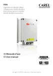
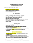
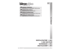
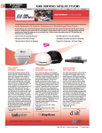
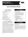
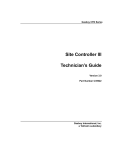
TopKAT Fuel Management System
Parts Manual
PT-1957
(formerly C35755)
Computer Programs and Documentation
All Gasboy computer programs (including software on diskettes and within memory chips) and documentation are copyrighted by, and shall remain the property of, Gasboy. Such
computer programs and documents may also contain trade secret information. The duplication, disclosure, modification, or unauthorized use of computer programs or
documentation is strictly prohibited, unless otherwise licensed by Gasboy.
Federal Communications Commission (FCC) Warning
This equipment has been tested and found to comply with the limits for a Class A digital device pursuant to Part 15 of the FCC Rules. These limits are designed to provide
reasonable protection against harmful interference when the equipment is operated in a commercial environment. This equipment generates, uses, and can radiate radio frequency
energy, and if not installed and used in accordance with the instruction manual, may cause harmful interference to radio communications. Operation of this equipment in a
residential area is likely to cause harmful interference in which case the user will be required to correct the interference at his own expense. Changes or modifications not expressly
approved by the manufacturer could void the user’s authority to operate this equipment.
Approvals
Gasboy, Greensboro, is an ISO 9001:2000 registered facility.
Underwriters Laboratories (UL):
New York City Fire Department (NYFD):
California Air Resources Board (CARB):
UL File#
MH4314
MH6418
MH7404
MH10581
Products listed with UL
NYFD C of A #
Product
Executive Order #
Product
All dispensers and self-contained pumping
units
Power operated Transfer Pump Models 25,
25C, 26, 27, 28, 72, 72S, 72SP, 72X, 73 and
1820
Hand operated Transfer Pump Models 1230
Series, 1243 Series, 1520 and 1720 Series
Key control unit, Model GKE-B Series
Card reader terminals, Models 1000, 1000P
Site controller, Model 2000S CFN Series
Data entry terminals, Model TPK-900 Series
Fuel Point Reader System
4823
9100A, 9140A, 9152A, 9153A,
9800A, 9840A, 9850A, 9852A,
9853A, 9140
9822A, 9823A
9100Q, 9140Q, 9152Q, 9153Q,
9800Q, 9840Q, 9852Q, 9853Q
G-70-52-AM
G-70-150-AE
Balance Vapor Recovery
VaporVac
4997
5046
National Conference of Weights and Measures (NCWM) - Certificate of Compliance (CoC):
Gasboy pumps and dispensers are evaluated by NCWM under the National Type Evaluation Program (NTEP). NCWM has issued the following CoC:
CoC#
Product
Model #
95-179A2
Dispenser
9100 Retail Series, 8700
91-019A2
Series, 9700 Series
CoC#
Dispenser
95-136A5
Dispenser
9800 Series
Controller
91-057A3
Product
Model #
CoC#
Product
Model #
9100 Commercial
Series
1000 Series FMS,
2000S-CFN Series
Patents
Gasboy products are manufactured or sold under one or more of the following US patents:
Dispensers
5,257,720
Point of Sale/Back Office Equipment
D335,673
Additional US and foreign patents pending.
Trademarks
Non-registered trademarks
Registered trademarks
Atlas™
Consola™
Infinity™
ASTRA®
Fuel Point®
Gasboy®
Keytrol®
Slimline®
This document is subject to change without notice. · For information regarding Gasboy Literature, call (336) 547-5661
E-mail: [email protected] · Internet: http://www.gasboy.com
© 2006 GASBOY · All Rights Reserved
Additional US and foreign trademarks pending.
Other brand or product names shown may be
trademarks or registered trademarks of their
respective holders.
Table of Contents
Table of Contents
1 – Introduction
1
Using This Parts List
1
Abbreviations and Acronyms
2
Important Safety Information
3
2 – Illustrated Parts List
5
Wrapper Assembly
5
Wrapper Assembly Parts . . . . . . . . . . . . . . . . . . . . . . . . . . . . . . . . . . . . . . . . 5
Optional Field Kits . . . . . . . . . . . . . . . . . . . . . . . . . . . . . . . . . . . . . . . . . . . . . 5
Parts as Viewed from Right and Rear Sides
6
Parts - Right Side . . . . . . . . . . . . . . . . . . . . . . . . . . . . . . . . . . . . . . . . . . . . . . 7
Parts - Right Rear Side . . . . . . . . . . . . . . . . . . . . . . . . . . . . . . . . . . . . . . . . . 7
Parts as Viewed from Top and Front Side
8
Parts - Top . . . . . . . . . . . . . . . . . . . . . . . . . . . . . . . . . . . . . . . . . . . . . . . . . . . 9
Parts - Front View . . . . . . . . . . . . . . . . . . . . . . . . . . . . . . . . . . . . . . . . . . . . . 9
Bezel - Parts as Viewed from Front and Rear
10
Bezel Parts - Front and Rear . . . . . . . . . . . . . . . . . . . . . . . . . . . . . . . . . . . . 11
Mechanical Interface - 2-Hose
12
Mechanial Interface Parts - 2-Hose . . . . . . . . . . . . . . . . . . . . . . . . . . . . . . . 12
Mechanical PCU - 4-to-8 Hose
13
Mechanial PCU Parts - 4-8 Hose . . . . . . . . . . . . . . . . . . . . . . . . . . . . . . . . . 14
PT-1957 TopKAT Fuel Management System Parts Manual · January 2006
Page i
Table of Contents
This page intentionally left blank.
Page ii
PT-1957 TopKAT Fuel Management System Parts Manual · January 2006
Using This Parts List
Introduction
1 – Introduction
Using This Parts List
This manual is designed to aid the authorized service contractor (ASC) or technician in
ordering replacement parts for the Series 900 TopKAT system.
!
WARNING
Electrical shock hazards exist in Gasboy Series 900 components. Gasboy
systems are to be serviced only by properly trained personnel. During the
warranty period, Gasboy systems must be serviced and repaired only by trained
ASCs (see the Warranty for details or contact your Gasboy representative). To
reduce the risk of electrical shock when servicing, turn off and lock out all breakers
which supply power to the Series 900 System (all components) at the master
electrical panel.
The drawings and part lists starting with “Illustrated Parts List” on page 5 provide an easy
reference for identifying Series 900 parts and their corresponding part numbers. Use the part
numbers when ordering to expedite your order and reduce the possibility of the wrong parts
being shipped. Multiple views of the system are provided to ensure all parts are identified.
Figure: 1-1 Typical TopKAT Installation
PT-1957 TopKAT Fuel Management System Parts Manual · January 2006
Page 1
Abbreviations and Acronyms
Introduction
Abbreviations and Acronyms
Page 2
Abbreviation or
Acronym
Expansion
A
Amp or Ampere
AC
Alternating Current
ASC
Authorized Service Contractor
BT
Battery
CFR
Code of Federal Regulations
CPR
Cardiopulmonary Resuscitation
CPU
Central Processing Unit
DC
Direct Current
IC
Integrated Circuit
LCD
Liquid Crystal Display
NEC
National Electrical Code
NFPA
National Fire Prevention Association
OSHA
Occupational Safety and Health Administration
PC
Printed Circuit
PCB
Printed Circuit Board
PCMCIA
Personal Computer Memory Card International Association
PCU
Pump Control Unit
PG
Plug
PROM
Programmable Read-Only Memory
SPST
Single Pole, Single Throw
SRAM
Static Random Access Memory
STP
Submerged Turbine Pump
T
Thickness
TB
Terminal Block
V
Volts
VAC
Volts AC
VDC
Volts DC
W
Width
PT-1957 TopKAT Fuel Management System Parts Manual · January 2006
Important Safety Information
Important Safety Information
This section introduces the hazards and safety precautions
associated with installing, inspecting, maintaining or servicing
this product. Before performing any task on this product, read
this safety information and the applicable sections in this
manual, where additional hazards and safety precautions for
your task will be found. Fire, explosion, electrical shock or
pressure release could occur and cause death or serious
injury if these safe service procedures are not followed.
Preliminary Precautions
You are working in a potentially dangerous environment of
flammable fuels, vapors, and high voltage or pressures. Only
trained or authorized individuals knowledgeable in the related
procedures should install, inspect, maintain or service this
equipment.
Emergency Total Electrical Shut-Off
The first and most important information you must know is
how to stop all fuel flow to the pump and island. Locate the
switch or circuit breakers that shut-off all power to all fueling
equipment, dispensing devices, and submerged turbine
pumps (STPs).
!
! WARNING
The EMERGENCY STOP, ALL STOP, and
PUMP STOP buttons at the cashierÕs station
WILL NOT shut off electrical power to the
pump/dispenser.
This means that even if you activate these
stops, fuel may continue to flow uncontrolled.
You must use the TOTAL ELECTRICAL SHUTOFF in the case of an emergency and not only
these cashier station Òstops.Ó
Total Electrical Shut-Off Before Access
Any procedure requiring access to electrical components or
the electronics of the dispenser requires total electrical shutoff of that unit. Know the function and location of this switch
or circuit breaker before inspecting, installing, maintaining, or
servicing Gasboy equipment.
Evacuation, Barricading and Shut-Off
Any procedures requiring accessing the pump/dispenser or
STPs requires the following three actions:
- An evacuation of all unauthorized persons and vehicles
using safety tape, cones or barricades to the effected units
- A total electrical shut-off of that unit
Read the Manual
Read, understand and follow this manual and any other
labels or related materials supplied with this equipment. If you
do not understand a procedure, call a Gasboy Authorized
Service Contractor or call the Gasboy Service Center at 1800-444-5529. It is imperative to your safety and the safety of
others to understand the procedures before beginning work.
Follow the Regulations
There is applicable information in NFPA 30A; Automotive and
Marine Service Code, NFPA 70; National Electrical Code (NEC),
OSHA regulations and federal, state, and local codes which
must be followed. Failure to install, inspect, maintain or
service this equipment in accordance with these codes,
regulations and standards may lead to legal citations with
penalties or affect the safe use and operation of the
equipment.
Replacement Parts
Use only genuine Gasboy replacement parts and retrofit kits
on your pump/dispenser. Using parts other than genuine
Gasboy replacement parts could create a safety hazard and
violate local regulations.
Safety Symbols and Warning Words
This section provides important information about warning
symbols and boxes.
Alert Symbol
This safety alert symbol is used in this manual and on
warning labels to alert you to a precaution which must be
followed to prevent potential personal safety hazards. Obey
safety directives that follow this symbol to avoid possible
injury or death.
Signal Words
These signal words used in this manual and on warning labels
tell you the seriousness of particular safety hazards. The
precautions that follow must be followed to prevent death,
injury or damage to the equipment
! DANGER - This signal word is used to alert you to a
hazard to unsafe practice which will result in death or
serious injury
! WARNING - This alerts you to a hazard or unsafe
practice that could result in death or serious injury.
! CAUTION with Alert symbol - This signal word
designates a hazard or unsafe practice which may
result in minor injury.
CAUTION without Alert symbol - When used by itself,
CAUTION designates a hazard or unsafe practice
which may result in property or equipment damage.
Working With Fuels and Electrical Energy
Prevent Explosions and Fires
Fuels and their vapors will become explosive if ignited. Spilled
or leaking fuels cause vapors. Even filling customer tanks will
cause explosive vapors in the vicinity of dispenser or island.
PT-1957 TopKAT Fuel Management System Parts Manual · January 2006
Page 3
Important Safety Information
Emergency First Aid
No Open Flames
Open flames from matches, lighters, welding torches
or other sources can ignite fuels and their vapors.
No Sparks - No Smoking
Sparks from starting vehicles, starting or using power tools,
burning cigarettes, cigars or pipes can also ignite fuels and
their vapors. Static electricity, including an electrostatic
charge on your body, can cause a spark sufficient to ignite
fuels and their vapors. After getting out of a vehicle, touch the
metal of your vehicle to discharge any electrostatic charge
before you approach the dispenser island.
Working Alone
It is highly recommended that someone who is capable of
rendering first aid be present during servicing. Be familiar
with Cardiopulmonary Resuscitation (CPR) methods if you
are working with or around high voltages. This information is
available from the American Red Cross. Always advise the
station personnel about where you will be working, and
caution them not to activate power while you are working on
the equipment. Use the OSHA tag out and lock out
procedures. If you are not familiar with this requirement, refer
to information in the service manual and OSHA
documentation.
Working With Electricity Safely
Be sure to use safe and established practices in working with
electrical devices. Poorly wired devices may cause a fire,
explosion or electrical shock. Be sure grounding connections
are properly made. Make sure that sealing devices and
compounds are in place. Be sure not to pinch wires when
replacing covers. Follow OSHA Lock-Out and Tag-Out
requirements. Station employees and service contractors
need to understand and comply with this program completely
to ensure safety while the equipment is down.
Hazardous Materials
Some materials present inside electronic enclosures may
present a health hazard if not handled correctly. Be sure to
clean hands after handling equipment. Do not place any
equipment in mouth.
!
WARNING
This area contains a chemical known to the State of
California to cause cancer.
!
WARNING
This area contains a chemical known to the State of
California to cause birth defects or other reproductive
harm.
IMPORTANT: Oxygen may be needed at scene if gasoline
has been ingested or inhaled. Seek medical advice
immediately.
Page 4
Informing Emergency Personnel
Compile the following information for emergency personnel:
Location of accident (for example, address, front/back of
building, and so on.)
Nature of accident (for example, possible heart attack, run
over by car, burns, and so on.)
Age of victim (for example, baby, teenager, middle-age,
elderly.)
Whether or not victim has received first aid (for example,
stopped bleeding by pressure, and so on.)
Whether or not a victim has vomited (for example, if
swallowed or inhaled something, and so on.)
WARNING
!
Gasoline ingested may cause unconsciousness
and burns to internal organs.
Do not induce vomiting.
Keep airway open.
Oxygen may be needed at scene.
Seek medical advice immediately.
!
WARNING
Gasoline inhaled may cause unconsciousness
and burns to lips, mouth and lungs.
Keep airway open.
Seek medical advice immediately.
!
WARNING
Gasoline spilled in eyes may cause burns to eye
tissue.
Irrigate eyes with water for approximately 15
minutes.
Seek medical advice immediately
!
!
WARNING
Gasoline spilled on skin may cause burns.
Wash area thoroughly with clear/water.
Seek medical advice immediately.
IMPORTANT: Oxygen may be needed at scene if gasoline
has been ingested or inhaled. Seek medical advice
immediately.
Lockout/Tagout
Lockout/Tagout covers servicing and maintenance of
machines and equipment in which the unexpected
energization or start up of the machine(s) or equipment or
release of stored energy could cause injury to employees or
personnel. Lockout/Tagout applies to all mechanical,
hydraulic, chemical or other energy, but does not cover
electrical hazards. Reference Subpart S of 29 CFR Part 1910
- Electrical Hazards, 29 CFR Part 1910.333 contains specific
Lockout/Tagout provision for electrical hazards.
PT-1957 TopKAT Fuel Management System Parts Manual · January 2006
Wrapper Assembly
Illustrated Parts List
2 – Illustrated Parts List
Wrapper Assembly
Figure: 2-1 TopKAT Wrapper Assembly
Wrapper Assembly Parts
Item
(see Figure 2-1)
Part Number
Description
1
C35656
Wrapper Weld Assembly, Series 900
2
C35659
Slide Bracket, Wrapper, Series 900
3
C09612
Screw, Captive Phillips®
4
C03286
Washer, Retaining, 12-11014-12
5
027065
Gasket, Bulk, 1/8T x 1/2W Self Adhesive
6
C01989
Gasket, Bulk, 1/4T x 1/2W Self Adhesive
Optional Field Kits
Part Number
Description
C06966
Field Installation, Internal Modem 2400 Baud (see Figure 2-3, item 21)
C07198
Field Installation, Internal Modem 33600 Baud (see Figure 2-3, item 21)
C07063
Field Installation, Report Printer
C06968
Field Installation, PCMCIA PCB
PT-1957 TopKAT Fuel Management System Parts Manual · January 2006
Page 5
Illustrated Parts List
Parts as Viewed from Right and Rear Sides
Parts as Viewed from Right and Rear Sides
Figure: 2-2 Series 900 - Partial Right Side View and Right Rear View
Page 6
\PT-1957 TopKAT Fuel Management System Parts Manual · January 2006
Parts as Viewed from Right and Rear Sides
Illustrated Parts List
Parts - Right Side
Item
(see Figure 2-2)
1
Part Number
Description
C35683
Rear Door Assembly (items 2 - 6 are subparts of this assembly)
2
035009
3
C35712
Lock Cam, Rear Door, Series 900
026808
Gasket, Lock (not shown)
4
C01989
Gasket, Bulk, 1/4T x 1/2W Self Adhesive
5
C35660
Hinge, Rear Door
049870
Pop Rivet
6
Lock, 90º with Cover and Seal, Black
7
C09518
Flexible Cable/Ring Assembly
8
C06859
Cable Assembly Ground Strap
9
C35673
Rain Gutter, Lower, Series 900
10
C35672
Rain Gutter, Upper, Series 900
11
C35689
Base Weld Assembly
12
C35675
Rain Gutter, Right Side
13
C35677
Rain Gutter, Left Side Assembly
14
C35694
Bracket Lock, Series 900
15
C35686
Gasket, Upper Gutter
16
C35687
Gasket, Side Gutter
17
C35685
Gasket, Lower Gutter
18
027078
Gasket, 1/16” x 1/2” Rubatex® R411N
19
C06740
PCB Assembly, PCMCIA
20
C09419
Standoff, 1/4-turn, 1/4” Plastic
21
C09849
Card, PCMCIA 256K SRAM with Battery (one of the indented parts below is
a part of this assembly)
C09625
Battery, Lithium Coin, #BR2325 (not shown)
~ OR ~
C09417
Battery, Lithium Coin, #CR2025 (not shown)
22
C06813
Cable Assembly, System Heaters, 115 VAC
23
C06757
Cable Assembly, Surge Protector, 115 VAC
Item
(see Figure 2-2)
Part Number
Description
24
C06815
Cable Assembly, System Heaters, 230 VAC
25
C06820
Cable Assembly, Surge Protector, 230 VAC
Parts - Right Rear Side
PT-1957 TopKAT Fuel Management System Parts Manual · January 2006
Page 7
Parts as Viewed from Top and Front Side
Illustrated Parts List
Parts as Viewed from Top and Front Side
Figure: 2-3 Series 900 - Top and Front View
C07037KTKxxx
Page 8
\PT-1957 TopKAT Fuel Management System Parts Manual · January 2006
Parts as Viewed from Top and Front Side
Illustrated Parts List
Parts - Top
Item
(see Figure 2-3)
Part Number
Description
1
C06498
PCB Assembly, Communications Ports
2
C06752
Cable Assembly, Ribbon, 20-position
3
C09419
Standoff, 1/4-turn, 1/4” Plastic
4
C08235
Connector, 5-position terminal block
5
C09435
Bushing, 1-5/16”
6
C06751
Cable Assembly, Ribbon, 10-position
7
C06750
Cable Assembly, CPU DC Power
8
C06753
Cable Assembly, Ribbon, 20-position
9
C35680
Mounting Bracket, Assembly, Power Supply - TopKAT
10
C06741
PCB Assembly, Series 900 CPU (indented parts below are part of this
assembly)
C09415
C07037KTKxxx
Battery, Lithium Coin, 3 V (not shown; for use in BT1 or BT2 location)
TopKAT Programmed IC PROM (two required for locations U1 and U5)
where xxx = one of the following:
• ENG (for English version)
• HTZ (for Hertz version)
• SPN (for Spanish version)
11
C02188
Bushing, Snap-in
12
C09546
Fuse Holder, 3AG Panel Mount
13
C02634
Fuse, 3 Amp
14
C03756
Bushing, Snap-in
Parts - Front View
Item
(see Figure 2-3)
Part Number
Description
15
C06756
Cable Assembly, AC Input Harness
16
C09053
Power Supply with Ground Wire
17
C35635
Cover Perforated Int Hsg
18
C08756
Label, Danger High Voltage
19
C06762
Cable Assembly, 2-conductor, Modem
20
C02896
Support, PC Board
21
C07122
Modem, Internal, 2400 Baud
~ OR ~
C07123
Modem, Internal, 33600 Baud
22
C09370
Power Supply, 5 V
23
C06812
Cable Assembly, Printer DC Power
24
C06755
Cable Assembly, Printer/Heater, 115 VAC
~ OR ~
C06748
Cable Assembly, Printer/Heater, 230 VAC
25
C35704
Heater Mounting Bracket
26
C35708
Cover, Printer Heater
27
C06745
Cable Assembly, Printer Serial/Logic
PT-1957 TopKAT Fuel Management System Parts Manual · January 2006
Page 9
Bezel - Parts as Viewed from Front and Rear
Illustrated Parts List
Bezel - Parts as Viewed from Front and Rear
Figure: 2-4 Series 900 - Front and Rear Views
Page 10
\PT-1957 TopKAT Fuel Management System Parts Manual · January 2006
Bezel - Parts as Viewed from Front and Rear
Illustrated Parts List
Bezel Parts - Front and Rear
Item
(see Figure 2-4)
Part Number
Description
1
003118
Bezel, Mach Series
2
C09512
Decal, TopKAT
3
035009
Lock, 90º with cover and seal
4
C35698
Cam Lock, Bezel
5
026808
Gasket, Lock
6
C09511
Decal, Gasboy Series
7
C35653
Cover, Key Receptacle
8
027065
Gasket, 1/8” x 1/2”
9
C35678
Bracket, Hinge Bezel
10
C06814
Display, 40-character, 2-row LCD
11
C09513
Decal, Insert Key
12
C35651
Key Receptacle Gasket
13
C35650
Key Receptacle Mounting Plate
14
C06499
PCB Assembly, Key Receptacle
15
C35652
Key Receptacle Mounting Bracket
16
C06495
PCB Assembly, Display/Keypad
17
C35646
Bracket Assembly, Display Mount, Series 900
18
C35647
Window Display
19
C06986
Cable Assembly, Ground Strap
20
C35720
Rain Gutter, Bezel
21
C06995
Keypad Kit (indented part below is part of this assembly)
22
C35649
Gasket, Keypad
23
C06739
PCB Assembly, Printer Controller
24
C35644
Bracket Support Printer
25
C35702
Paper Roll Support Shaft
26
C09414
Printer, Thermal, 24-column
27
C35701
Paper Roll Secure Bracket
28
C01819
Paper, Thermal
29
C35705
Bracket, Paper Deflector
30
C35719
Stop Cover Chute
31
C06849
Cover Weld Assembly, Chute
32
C35638
Paper Guide, Front
33
C35707
Paper Guide, Front
34
C35640
Paper Deflector, Upper
35
026980
Gasket, 1/16” x 1/8” x 3’
36
C35695
Cover, without Printer
PT-1957 TopKAT Fuel Management System Parts Manual · January 2006
Page 11
Mechanical Interface - 2-Hose
Illustrated Parts List
Mechanical Interface - 2-Hose
Figure: 2-5 Series 900 - Mechanical Interface - 2-Hose View
Mechanial Interface Parts - 2-Hose
Item
(see Figure 2-5)
Page 12
Part Number
Description
1
C35890
Terminal Block, Cover, 8-position
2
C06754
Cable Assembly, 8-position Terminal Block to Relays
3
C08746
Relay, Solid-State, 240 VAC, 40A SPST
4
C04477
Relay, Solid-State, 240 VAC, 25A SPST
5
C09419
Standoff, 1/4-turn, 1/4” Plastic
6
C02188
Bushing, Snap-in, 5/8” Diameter
7
C06493
PCB Assembly, Mechanical Pump Option
8
C06747
Cable Assembly, PC Relay Input
9
C06749
Cable Assembly, Mechanical Pump Control DC Power
10
C06752
Cable Assembly, Ribbon 20-position, 4” length
11
C08809
Connector, 6-position, TB/PG
12
C01846
Fuse, 2 Amp, Quick Blow, Pico, Axial
13
C03315
Connector, 2-position Jumper, Female, 0.100”
\PT-1957 TopKAT Fuel Management System Parts Manual · January 2006
Mechanical PCU - 4-to-8 Hose
Illustrated Parts List
Mechanical PCU - 4-to-8 Hose
Figure: 2-6 Series 900 - Mechanical PCU - 4-8 Hose View
PT-1957 TopKAT Fuel Management System Parts Manual · January 2006
Page 13
Mechanical PCU - 4-to-8 Hose
Illustrated Parts List
Mechanial PCU Parts - 4-8 Hose
Item
(see Figure 2-6)
Part Number
Description
1
C06600
Cage Assembly
2
C06591
Cable Assembly, DC Power, 4-Hose Unit
C06590
Cable Assembly, DC Power, 8-Hose Unit
3
C06593
Cable Assembly, Relay Control
4
C06005
Cable Assembly, PCU Communications, 4-Hose Unit
C06009
Cable Assembly, PCU Communications, 8-Hose Unit
5
C05052
Relay and Cable Assembly
6
C02418
Decal, Numbers 1, 2, 3, 4
7
C05059
Power Supply Assembly
8
C06592
Cable Assembly
9
C08237
Connector, 8-position
10
C08528
Connector, 12-position
~ OR ~
~ OR ~
Page 14
11
C32731
Plate, Silkscreened
12
C02293
Decal, Numbers 1, 2, 3, 4
13
C02952
Decal, Numbers 5, 6, 7, 8
\PT-1957 TopKAT Fuel Management System Parts Manual · January 2006
Phillips® is a registered trademark of the Phillips Screw Company
Rubatex® is a registered trademark of Rubatex International, LLC
© 2006 GASBOY
7300 West Friendly Avenue • Post Office Box 22087
Greensboro, North Carolina 27420
Phone 1-800-444-5529 • http://www.gasboy.com • Printed in the U.S.A.
PT-1957 TopKAT Fuel Management System Parts Manual · January 2006