1
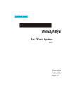
Service Manual
LS 135/150 Examination Light
443194 Rev. B
Welch Allyn Medical Division
4341 State Street Road
P.O. Box 220
Skaneateles Falls, NY 13153-0220
Copyright 2002
Rev
Description
ECN #
Date
Approved
443194
A
New Release of LS 135 / LS 150
Exam Light Service Manual
5-44889
07/08/2002
DK/RS
443194
B
Changed Cautions and warnings
Changed Section 4
Changed bubble numbers
5-45188
10/29/2002
DK
Part No
Drawings and/or illustrations and/or part numbers contained in this document
are for reference purposes only. For current revisions call the Welch Allyn
Customer Service phone number listed in Section 1 page 3.
LS 135/LS 150 Service Manual 443194 Rev. B
Welch Allyn Exam Light i
Contents
Section 1:
General Information
About the LS 135................................................................................................................................1
About the LS 150 ...............................................................................................................................1
Approvals ............................................................................................................................ 1
Safety Warnings. .................................................................................................................. 2
Help Information................................................................................................................................3
Section 2:
Service
Incoming Inspection/Checklist ........................................................................................... 1
Required Tools .................................................................................................................... 1
Section 3:
Troubleshooting
Mechanical checks .............................................................................................................. 1
Electrical checks.................................................................................................................................2
Section 4:
Repair and Disassembly
LS 135 Floor Model Dissambly ........................................................................................... 1
LS 135 Wall Model Dissambly.........................................................................................................9
LS 150 Wall Model Dissambly .......................................................................................... 14
LS 150 Floor Model Dissambly.....................................................................................................17
Appendix A: Repair Parts Lists
Appendix B: Exploded View Photo Illustrations
Appendix C:
Electrical Schematic
ii Welch Allyn Exam Light
LS 135/LS 150 Service Manual 443194 Rev. B
General Information
Section 1
About the LS 135 Examination Light
The LS 135 examination light is a 35-watt halogen light that produces significantly whiter, brighter light than
the ordinary gooseneck units. The dual intensity control switch allows you to instantly adjust light output to
meet your exact requirements. A molded lexan light head does not conduct heat, keeping the luminaire cool
to the touch. Multiple installation options include floor stand, table mount, wall mount and caster base.
About the LS 150 Examination Light
The LS 150 features a color corrected 50 watt lamp that delivers superior light quality across the
variable spectrum for more accurate color rendition. The special designed light head keeps the luminaire
cool to the touch even during multiple exams. The lamp has been offset at a 12 degree angle relative to the
luminaire housing, allowing an unobstructed view of the field of interest.
Approvals
ETL listed
UL2601-1,
CSA C22.2 No. 601.1
US IEC 60601-1, AS 3200.1
IEC 60601-1-2
C
The CE mark on this product indicates that it
has been tested to and conforms with the
provisions noted within the 89/336/ECC
Electromagnetic Compatibility Directive.
Australia EMC Framework Compliance
N344
LS 135/150 Service Manual 443194 Rev. B
Welch Allyn Exam Light 1
Section 1
General Information
Cautions and Warnings
INTENSE LIGHT: Lamp is extremely bright. Do not stare at the lamp
when in use. May be harmful to eyes.
CAUTION: Remove power cord from electrical outlet and allow
lamp to cool 10 minutes before replacing with Welch Allyn lamp.
DANGER: Electric Shock Hazard. Refer servicing to qualified
service personnel.
DANGER: Risk of explosion if used in the presence of flammable
anesthetics.
HOT SURFACE: Lamp surface is hot. May be harmful to skin if
touched.
NOTE: This product complies with current required standards for electromagnetic
interference and should not interfere with other equipment or be affected by other
compliant devices. As a precaution, avoid using this device in close proximity to other
equipment.
2 Welch Allyn Exam Light
LS 135/150 Service Manual 443194 Rev. B
General Information
Help Information
Section 1
To assure correct operation and performance all service and repairs must be performed
by fully trained and properly equipped personnel, using genuine replacement parts and
correct procedures. Failure to do so will also invalidate the product warranty.
When calling, refer to the model number on the head of the Exam light.
Welch Allyn Inc.
State Street Plant /Corporate Headquarters
4341 State Street Road
Skaneateles Falls, NY 13153 0220, USA
Welch Allyn UK Ltd
St. Georges House
Vernon Gate, Derby
England DE1 1UQ
tel:
1 800 535-6663
315 685 4100
fax:
315 685 3361
www.welchallyn.com/medical/support/tech
tel:
fax:
mob:
Welch Allyn Canada Ltd.
160 Matheson Blvd. E., Unit #2
Mississauga, Ontario Canada L4Z 1V4
Welch Allyn Australia Pty
Metro Centre Unit 5
38-46 South Street
Rydalmere NSW 2116, Australia
Postal address:
PO Box 132
Rydalmere NSW 1701, Australia
tel:
fax:
1-800-561-8797
905-890-0004
905-890-0008
MD International
11300 N.W. 41st Street
Miami, FL 33178 USA
tel:
fax:
305-669-9003
305-669-1971
Welch Allyn GMBH
Zollerstrasse 2 4
72417 Jungingen, Germany
tel:
fax:
(011) 49 7477 927186
(011) 49 7477 927193
Welch Allyn France SARL
814 rue Charles de Gaulle
77100 Mareuil les Meaux
France
tel:
Fax:
(011) 33.1.6009.3366
(011) 33.1.6009.6797
tel:
fax:
(011) 612 9638-3000
(011) 612 9638-3500
Welch Allyn Singapore Ltd
300 Beach Road, #25-08
The Concourse
Singapore 199589, Singapore
tel:
fax:
(011) 65-291-0882
(011) 65-291-5780
China Service Center
Room 708, Central Plaza
No. 227 Huang Pi Bei Road
Huang Pu District
Shanghai 200003
China
tel:
fax:
(011) 86-21-63279631
(011) 86-21-63279632
Welch Allyn Japan K.K.
Bon Marusan 8F, 3-5-1 Kanda
Jinbo-Cho, Chiyoda-Ku
Tokyo 101-0051
Japan
tel:
fax:
LS 135/150 Service Manual 443194 Rev. B
(011) 44-01332-206208
(011) 44-01332-206209
(011) 44-0467-301814
(011) 813-5212-7391
(011) 813-3261-7372
Welch Allyn Exam Light 3
BLANK PAGE
Service
Incoming Inspection
Section 2
NOTE: Use the following guidelines when unpacking the Exam Light from its shipping
carton.
1. Before opening the Exam Light shipping carton, check for damage.
2. If damage is apparent, stop unpacking the carton and contract the shipping company for
further instructions. If the carton is intact, unpack the Exam Light.
3. With the Exam Light out of its carton, check to see that all the items listed on the
packing slip are in the shipping carton.
4. If an item is missing, first check the carton, then check with your receiving
department. If necessary contact Welch Allyn at the Address and phone number
shown in Section 1 .
5. Clean and disinfect by following the instructions printed in the Operator Manual.
NOTE: Perform all functional tests before and after servicing.
6. Operate the Exam Light to verify the customer complaint before making any changes to
theunit. Call the customer if the complaint is unclear.
7. If the unit has caused or is suspected of having caused an injury of any type:
DO NOT DISASSEMBLE OR REPAIR THE UNIT IN ANY WAY.
Contact Welch Allyn Customer Service immediately.
Tools Required For Servicing Exam Light
Phillips Screw Driver
Standard Slip Joint Pliers
Needle Nose Pliers
Snap Ring Pliers
3/32 Hex Wrench
Pin removal tool
Digital MultiMeter
LS 135/LS 150 Service Manual 443194 Rev. B
Welch Allyn Exam Light 1
BLANK PAGE
Troubleshooting
Mechanical Checks:
Section 3
1. Gooseneck - Replace if:
The shrink wrap is cracked/damaged or pulled back from either end.
The Gooseneck is damaged or kinked.
If it does not hold position - “droops” when checked in 4 directions.
2. Crush Rib Sleeve and Bushing: Replace if:
Damaged, cracked, or if o-rings are worn.
3. Head Rotation:
Position Head so it is parallel to the floor.
Rotate Head into several positions - it should hold in any position placed.
If it does not hold, replace the Bushing and o-rings on the Gooseneck.
4. If the reason for repair is due to rotation issues:
Turn on the unit & allow it to warm up 15 - 20 minutes, then check the rotation.
If it does not hold, replace the Bushing and o-rings on the Gooseneck.
5. Housings - Head or Base:
Replace any that have damage or cracks.
Check the Head housings for hairline cracks around the Bushing. Replace as needed.
6. Pole:
Replace any Poles that are bent.
7. Wire Harnesses/Connectors - Replace if:
Pinched, broken, or wire is exposed.
Electrical Checks:
The unit should NOT be plugged in at this time.
1. If Pole is not attached to the Base, check the wires at the both ends of the Pole, if wires
appear not damaged, assemble Pole into the Base.
2. Check for damaged or pinched wires at the connection between the Pole and Gooseneck.
3. Plug in unit (do not do this if any wires are damaged). Turn on unit.
Lamp works:
1. Turn Switch off and on several times. Light should not flicker while turned on. If you
are testing the LS 135 there should be an obvious change in light output between the
low & high settings. Switch should be consistent.
LS 135/150 Service Manual 443194 Rev. B
Welch Allyn Exam Light 1
Section 3
Troubleshooting
Lamp does not work:
1. Turn off unit and unplug it. Check for blown or incorrect Lamp. Lamp should be 35W,
12V for the LS 135. Welch Allyn Part# 443069. Lamp should be 50 watt for the LS 150.
Welch Allyn Part# 445013.
2. Check connections between Pole and Gooseneck, the Base and Pole, and the Head and
theGooseneck.
3. If lamp still does not light then turn off unit.
4. Unplug it check the fuses located in the base.
5. If unit still does not light, perform Floor Model Switch Function Test.
Floor Model Switch Function Test (LS 135 Only)
Note: For this test, Unit should be unplugged from outlet! A known good Lamp should
be installed.
1. Disconnect Gooseneck Harness from Pole Harness.
2. Check for correct wire order:
Pin 1 = Red, Pin 2 = Yellow, Pin 3 = White.
3. Set the meter to the lowest resistance setting.
4. Put one meter lead into the white wire pin and the other into the yellow wire pin.
5. Set the Switch on the Lamp Head to the low setting. The meter should read less than 1
ohm of resistance.
6. Set the Switch to the off position. The meter should read open.
7. Move meter lead from the yellow wire pin to the red wire pin.
8. Set the Switch on the Lamp Head to the high setting. The meter should read less than 1
ohm of resistance.
9. Set the Switch to the off position. The meter should read open.
2 Welch Allyn Exam Light
LS 135/150 Service Manual 443194 Rev. B
Disassembly and Repair
LS 135 Floor Model
Section 4
NOTE: Disassembly of LS-135 Floor
model.
1. Loosen the screw that secures the
lamp nose assembly.
2. Lift lamp nose assembly.
3. Release the lamp retaining spring.
LS 135/150 Service Manual 443194 Rev. B
Welch Allyn Exam Light 1
Section 4
LS 135 Floor Model
Disassembly and Repair
4. Unplug lamp.
5. Remove lamp head by removing 5
screws.
6. Remove lamp bottom housing.
2 Welch Allyn Exam Light
LS 135/150 Service Manual 443194 Rev. B
LS 135 Floor Model
Disassembly and Repair
Section 4
LS-135 Reassembly Note: Notice wire tie
and placement of wire behind standoff.
7. To disassemble, disconnect wires and
remove gooseneck from lamp head.
Reassembly Note:
NOTE: wire /switch connections and
placement of wire behind standoff.
white wire
red wire
yellow wire
brown lamp socket wires
8.
Use small flat blade screwdriver to
pry the tabs of pole then pull
gooseneck bushing out.
Reassembly Note: Press the tabs back in
with a blunt object. A screwdriver
handle is shown below.
POLE
POLE
LS 135/150 Service Manual 443194 Rev. B
Welch Allyn Exam Light 3
Section 4
Disassembly and Repair
LS 135 Floor Model
9. Gooseneck assembly can be
disassembled as per the following steps.
Note: Colors of wiring harness
on pole-end of gooseneck.
Red wire is in ‘key’ side of
connector.
YELLOW
WHITE
RED
10. Use pin removal tool to remove
connector block.
4 Welch Allyn Exam Light
LS 135/150 Service Manual 443194 Rev. B
Disassembly and Repair
LS 135 Floor Model
Section 4
11. Use 3/32” hex key to remove screw.
3/32” hex key
12. Pull bottom bushing away from
flexible arm.
Note the o-rings on lower flex bushing.
13. Remove snap ring from upper flex
bushing.
LS 135/150 Service Manual 443194 Rev. B
Welch Allyn Exam Light 5
Section 4
LS 135 Floor Model
Disassembly and Repair
14. Remove upper bushing from flexible
arm.
Note: View of completely disassembled
gooseneck assembly and wire
harness.
15. To remove pole from base, remove
screw and bottom plate.
6 Welch Allyn Exam Light
LS 135/150 Service Manual 443194 Rev. B
Disassembly and Repair
LS 135 Floor Model
Section 4
16. Disconnect ground.
17. Disconnect harness.
18. Remove 5 screws from base.
Remove top cover.
LS 135/150 Service Manual 443194 Rev. B
Welch Allyn Exam Light 7
Section 4
LS 135 Floor Model
Disassembly and Repair
NOTE: View of wiring and fuses:
(domestic LS-135 Pole Model)
Model:
44300
Application: Fuse Part #
DOM #6
236706-3114
44302
EUR
236706-3112
44303
JAP
488307-4
44304
UK
236706-3112
44306
AUST
236706-3112
NOTE: View of transformer
(domestic LS-135 Pole Model):
See APPENDIX C for wiring schematic of
your country.
Reassembly Note:
Carefully align wires in groove to
prevent damage to insulation when
inserting pole in base.
8 Welch Allyn Exam Light
LS 135/150 Service Manual 443194 Rev. B
Disassembly and Repair
LS 135 Wall Model
Section 4
NOTE: The 135 wall mount version of the
exam lamp is similar to the 135 floor model.
The heads are identical in every way. The
major difference is the transformer module and one continuous cord running from
it up to the head.
19. Remove phillips screw . Tilt nose up and
remove. Unplug Lamp connector.
20. Lift lamp nose assembly.
21. Release the lamp retaining spring.
LS 135/150 Service Manual 443194 Rev. B
Welch Allyn Exam Light 9
Section 4
LS 135 Wall Model
Disassembly and Repair
22. Unplug lamp.
23. Remove lamp head by removing 5
screws.
24. Remove housing.
10 Welch Allyn Exam Light
LS 135/150 Service Manual 443194 Rev. B
LS 135 Wall Model
Disassembly and Repair
Section 4
Note wire tie and placement of wire
behind standoff.
25. To disassemble, disconnect wires and
remove gooseneck from lamp head.
Reassembly Note:
NOTE: wire /switch connections and
placement of wire behind standoff.
white wire
red wire
yellow wire
brown lamp socket wires
Note: For Reassembly of all floor and
stand LS-135, Install switch according to
this photo.
LS 135/150 Service Manual 443194 Rev. B
Welch Allyn Exam Light 11
Section 4
LS 135 Wall Model
Disassembly and Repair
26. Remove the hex nut to remove
mounting plate.
27. Remove bushing from mounting
plate.
Note: The removal of bushing from wall
mount bracket.
12 Welch Allyn Exam Light
LS 135/150 Service Manual 443194 Rev. B
Disassembly and Repair
LS 135 Wall Model
Section 4
Note: The X on bushing should be
reinstalled toward mounting plate.
Note: The wiring route to switch, transformer.
Note: The wire color codes and orientation, strain relief, tie wrap to secure
wires. See Appendix C “WIRING DIAGRAMS” for the correct voltage wiring
connections. Each country has different voltage wiring connection.
LS 135/150 Service Manual 443194 Rev. B
Welch Allyn Exam Light 13
Section 4
LS 150 Wall Model
Disassembly and Repair
NOTE: Complete parts package for
LS150 table/wall mount.
1. Completely unscrew to remove nose
assembly from head.
NOTE: Notice wiring connections to
power switch, PCB and wiring
orientation.
14 Welch Allyn Exam Light
LS 135/150 Service Manual 443194 Rev. B
Disassembly and Repair
LS 150 Wall Model
Section 4
2. Completely unscrew hex nut to
remove flexible arm.
NOTE: Make sure bushing with X
marks are reinstalled toward
hex nut.
NOTE: Bushing with X indicator
marks are attached toward
mounting plate.
LS 135/150 Service Manual 443194 Rev. B
Welch Allyn Exam Light 15
Section 4
LS 150 Wall Model
Disassembly and Repair
3. Remove bushing from mounting plate.
NOTE: Notice the wiring routing and
wire connections.
16 Welch Allyn Exam Light
LS 135/150 Service Manual 443194 Rev. B
Disassembly and Repair
LS 150 Floor Model
Section 4
NOTE: Disassembly of LS-150 Floor
model.
1. Loosen the screw that secures the
lamp nose assembly.
2. Lift lamp nose assembly.
3. Release the lamp retaining spring.
LS 135/150 Service Manual 443194 Rev. B
Welch Allyn Exam Light 17
Section 4
LS 150 Floor Model
Disassembly and Repair
4. Unplug lamp.
5. Remove lamp head by removing 5
screws.
NOTE: Notice wiring connections to
power switch, PCB and wiring
orientation.
18 Welch Allyn Exam Light
LS 135/150 Service Manual 443194 Rev. B
Disassembly and Repair
LS 150 Floor Model
Section 4
NOTE: Notice switch orientation.
6. Use small flat blade screwdriver to
pry the tabs of pole then pull
gooseneck bushing out.
Reassembly Note: Press the tabs back in
with a blunt object. A screwdriver
handle is shown below.
7. Remove both pins from connector using
a pin removal tool.
NOTE: There are two wires going to
connector. Remember that they go in the
outer channels of the connector.
LS 135/150 Service Manual 443194 Rev. B
Welch Allyn Exam Light 19
Section 4
LS 150 Floor Model
Disassembly and Repair
NOTE: The gooseneck with wiring and
connector removed.
8. Use 3/32” hex key to remove screw.
9. Remove snap ring from upper flex
bushing.
20 Welch Allyn Exam Light
LS 135/150 Service Manual 443194 Rev. B
Disassembly and Repair
LS 150 Floor Model
Section 4
10. Remove upper bushing from flexible
arm.
11. To remove pole from base, remove
screw and bottom plate.
12. Disconnect ground.
LS 135/150 Service Manual 443194 Rev. B
Welch Allyn Exam Light 21
Section 4
LS 150 Floor Model
Disassembly and Repair
13. Disconnect harness.
14. Pull bottom pole from base.
NOTE: When reassembling the pole back
into the base, make sure wires fit
into the base channel.
15. Remove both pins with a pin removal
tool.
NOTE: The two red wires are to go in the
two outer positions of the connector.
22 Welch Allyn Exam Light
LS 135/150 Service Manual 443194 Rev. B
Disassembly and Repair
LS 150 Floor Model
Section 4
NOTE: The wire and connector removed
from the pole
16. Remove 5 screws from base then
remove top cover.
NOTE: Notice transformer and how wiring
is routed in the base.
LS 135/150 Service Manual 443194 Rev. B
Welch Allyn Exam Light 23
Section 4
LS 150 Floor Model
Disassembly and Repair
NOTE: Notice the fuses and connector and
how the wiring is routed.
See the repair parts lists for proper fuse
according to your country.
24 Welch Allyn Exam Light
LS 135/150 Service Manual 443194 Rev. B
Repair Parts List
Part #
443051-1
106108-20
106100-14
445013
443019-1
443121
443017-6
488067-501
106124-13
440029-1
445043
445020
445015
443078
761077-1
488073-502
106124-34
443083
445040
790007
443018
443103
488077
443017-5
443032
443069
455508
106124-44
443094-1
443189
443096-2
106124-43
445009-501
483412
443022-501
445027
440128
440009-1
440009-2
440009-4
440009-6
745184
443073-1
443074
745184
Appendix A
Description
WIRE FORM LAMP HOLDER
O-RING,.114 X .070, EPDM 70D
PHPS 8-32 X.375
50 WATT LAMP W/COVER GLASS
LAMP NOSE HSG. WHITE
HEAT SHIELD, NOSE
LAMP HSG,TOP LS150
RECTIFIER BOARD
#2 X 1/4 SCREW-PLASTITE
SWITCH,POWER SPST
M4.8X9.5 TAPPING,PAN,PH,SCREW
LS 150 PLATE, FAN MOUNTING
FAN
RETAINING RING
WIRE TIE
WIRE HARNESS LAMP/REC.BOARD
#4 X.375 PLASTITE PHPS
WIRE TIE W/MOUNTING HOLE
JUMPER
COVER SCREW #6 X 1/2 LG
LAMP HSG,BOTTOM
PLATE, HEAT DIFFUSER
Lamp Connector LS 135
LAMP HSG,TOP LS-135
SWITCH,SPOT POWER, 35W
35 WATT LAMP
Ground Label Base LS 135/150
8-32 X .500" SCREW
GROUND WIRE COVER PLATE
CLOSED END SPLICE
GROUND WIRE,MAIN
#6X1.687 PL PAN,PHILLIP
LS 150 TRANS. ASSY. 50 W DOM
#8 EXTERNAL LOCKWASHER
LS135 TRANS.ASSY,35W DOM
Plug 3 connector LS 135/150
SCHURTER FUSE BLOCK
LS 135/150 Floor Model Power Cord Assy. Domestic
LS 135/150 Floor Model Power Cord Assy. Europe
LS 135/150 Floor Model Power Cord Assy. UK
LS 135/150 Floor Model Power Cord Assy. Aust.
Strain Relief LS 135/150 Floor Model UK,Eur,Aust
Strain Relief LS 135/150 Floor Model Domectic
Plate Strain relief Domestic/Japan
Plate Strain relief Eur/UK/Aust
LS 135/150 Service Manual 443194 Rev. B
Bubble #
1
2
3
4
5
6
7
8
9
10
11
12
13
14
15
16
17
18
19
20
21
22
23
24
25
26
27
28
29
30
31
32
33
34
35
36
37
38
38
38
38
39
39
40
40
Welch Allyn Exam Light
1
Appendix A
Part #
236706-3114
236706-3112
488307-4
445010-1
443071-1
106130-11
106124-41
488307-3
236706-3117
443167-1
745150
443016
441107
236733
488042
441124-503
236732
711420-1
443157
440107
106113-10
443059-501
106124-18
761076-0
761076-2
761076-4
761076-6
443014
443153-1
443098
443091
488116
443043
443015
443105
610068
443020
440090-2
106108-7
440136
482038
106119-3
443079-1
106100-56
106106-4
Repair Parts List
Description
FUSE 500MA- Domestic
Fuse 315MA- Europe/United Kingdom
Fuse 630MA- Japan
TRANSFORMER, 50W
TRANSFORMER, 35W
RECEPTACLE,QUICK CONNECT 12-18
SCREW,#6X1.375 PL.PAN/PHILLIPS
FUSE-800 MA Domestic/Eur/Aust
Fuse 1A LS150- Japan
CABLE ASSY, WALL MOUNT
STRAIN RELIEF
WEIGHT, LS150
STRAP, TRANSFORMER
FUSE DRAWER
WIRE HARNESS,PWR MOD/GROUND
TRANSFORMER HOUSING SET
IEC CONNECTOR
SELF TAPPING SCREW .50
SLIT TUBING, CUT
WALL MOUNT BRACKET
10-32 X.312 HX DR SET SCREW
GOOSENECK ASSY W/END BUSHINGS
#8 X 1.25 SELF TAPPING SCREW
POWER CORD, DETACH.(DOMESTIC/JAPAN)
POWER CORD, DETACH.(EUROPE)
POWER CORD, DETACH.(UNITED KINGDOM)
POWER CORD, DETACH.(AUSTRALIA)
BASE, TOP COVER
POLE,POWDER COATED
WIRE HARNESS BASE/GN 35W
PLUG,MATE-N-LOCK (AMP)
WIRE TIE
CAP,3 CIRCUIT MATE-N=LOCK
LS 135/LS150 BASE,BOTTOM
O-RING .426 X .070
RETAINING RING
GOOSENECK BUSHING HEAD
CRUSH RIB SLEEVE
O-RING
GooseNeck LS 135/150
O-RING
4-40 X .125 SHCS
BASE COVER PLATE,PLATED
1/4-20 X 1"PAN HEAD PHILLIPS
EXTRNL LOCKWASHER
2 Welch Allyn Exam Light
Bubble #
41
41
41
42
43
44
45
46
46
47
48
49
50
51
52
53
54
55
56
57
58
59
60
61
61
61
61
62
63
64
65
66
67
68
69
70
71
72
73
74
75
76
77
78
79
LS 135/150 Service Manual 443194 Rev. B
Repair Parts List
Part #
443062-501
443085-501
445014-501
488082
443101
443190
445017
106124-40
445030
443184-501
445021-501
440078-4
Description
MOUNTING KIT,LS 135/LS 150
GOOSENECK ASSY
Fan Assembly, LS 150
MOLEX CONNECTOR
WIREHARNESS, Goose neck LS 150 Floor
CAUTION LABEL
WIRE HARNESS,SW/RECT.BD.50W
#6 X .625 PLASTITE LS 135/150 Base
WIRE HARNESS,BASE/GOOSE NECK LS 150
HARDWARE KIT, LS 135/150 WALL MOUNT
WIRE HARNESS,GOOSENECK HD,50W
STRAIN RELIEF
LS 135/150 Service Manual 443194 Rev. B
Appendix A
Bubble #
80
81
82
83
84
85
86
87
88
89
90
91
Welch Allyn Exam Light
3
BLANK PAGE
Electrical Schematics
LS 135
LS 135/150 Service Manual 443194 Rev. B
Appendix C
Welch Allyn Exam Light 1
Appendix C
2 Welch Allyn Exam Light
LS 150
Electrical Schematics
LS 135/150 Service Manual 443194 Rev. B