1
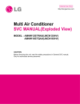
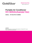
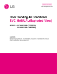
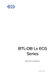
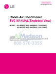
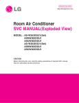
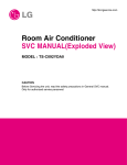
Internal Use Only
http://biz.lgservice.com
Floor Standing Air Conditioner
SVC MANUAL(Exploded View)
MODEL : APNH2433LAE[LFN246HV]
CAUTION
Before Servicing the unit, read the safety precautions in General SVC manual.
Only for authorized service personnel.
Specifications
1. Specifications
Indoor Unit
APNH2433LAE
Model
Power Supply
Cooling Capacity
Heating Capacity
Current
Fan
Coil
Dimensions
(W x H x D)
Net Weight
Nominal Running Current
Motor Type
Fan Type
Motor Output(W) x No. of Unit
Air Flow Rate(H / M / L)
External Static Pressure
Capacitor
Row x Column x FPI
Body
Decorative Panel
Body
Decorative Panel
Air Filter
Sound Level (H / M / L)
Piping Connections Liquid
Gas
Dehumidification Rate
Safety Devices
Temperature Sensor
Referigerant
Referigerant Control
Connectable Outdoor Unit
Power and Transmission Interunit Cable
Ø / V / Hz
kW
Btu/h
kW
Btu/h
A
1 / 208-230 / 60
7.03
24000
7.6
26000
10.9
OBM-4011U1
Turbo Fan
70x1
20/16.5/13
706/583/459
220/450
2R x 30C x 18
570x1820x320(22.4x71.6x12.6)
43(94.8)
Long life filter
45/42/40
9.52(3/8)
15.88(5/8)
Thermal protector for fan motor
Thermistor
R-410A
EEV(Outdoor Unit)
LUU245HV
4 x 18
CMM
cfm
mmAq
μF / Vac
mm(inch)
mm(inch)
kg (lbs)
kg (lbs)
dB(A)+3
mm (inch)
mm (inch)
l/h
No. x AWG
Note :
1. Capacities are based on the following conditions:
Cooling - Indoor temperature 27°C(80.6°F)DB/19°C(66.2°F)WB
- Outdoor temperature 35°C(95°F)DB/ 24°C(75.2°F)WB
Heating - Indoor temperature 20°C(68°F)DB/ 15°C(59°F)WB
- Outdoor temperature 7°C(44.6°F)DB/ 6°C(42.8°F)WB
Piping Length - Interconnecting Piping Length 7.5m
- Level Difference of Zero
2. Wiring cable size must comply with the applicable local and national code.
3. The specification may be subject to change without prior notice for purpose of improvement.
Copyright ©2010 LG Electronics. Inc. All right reserved.
Only for training and service purposes
-2-
LGE Internal Use Only
Function Table
2. Function Table
Indoor Unit
Category
Air flow
Air purifying
Installation
Reliability
Convenience
Individual control
CAC network function
Special function kit
Others
Function
Air supply outlet
Airflow direction control(left & right)
Airflow direction control(up & down)
Auto swing(left & right)
Auto swing(up & down)
Airflow steps(fan/cool/heat/Plasma)
Chaos swing
Chaos wind(auto wind)
Jet cool(Power wind)
Swirl wind
Deodorizing filter
Plasma air purifier
Prefilter(washable / anti-fungus)
Drain pump
E.S.P. control
Electric heater(operation)
High ceiling operation
Hot start
Self diagnosis
Soft dry operation
Auto changeover
Auto cleaning
Auto operation(artificial intelligence)
Auto restart operation
Child lock
Forced operation
Group control
Sleep mode
Timer(on/off)
Timer(weekly)
Two thermistor control
Standard wired remote controller
Deluxe wired remote controller
Simple wired remote controller
Wired remote controller(for hotel use)
Wireless remote controller(simple)
Wireless LCD remote control
General central controller (Non LGAP)
Dry contact
Network Soluation(LGAP)
PDI(power distribution indicator)
PI 485
Zone control
CTIE
Electro thermostat
Thermistor
APNH2433LAE
3
O
O
O
O
3/3/3/1
X
O
O
X
O
O
O
X
X
O
X
O
O
O
O
X
X
O
O
O
O
X
O
X
O
X
X
X
X
X
O(New)
X
X
X
X
X
X
X
X
X
Note:
O : Applied X : Not applied - : No relation
Option : Model name & price are different according to options, and assembled in factory with main unit.
Accessory : Installed at field, ordered and purchased separately by the corresponding model name, supplied with separate package
Copyright ©2010 LG Electronics. Inc. All right reserved.
Only for training and service purposes
-3-
LGE Internal Use Only
Piping Diagrams
3. Piping Diagrams
Heat Exchanger
Th2
:Cooling
:Heating
Th4
Th3
Sirocco Fan
lndoor unit
Th1
Liquid Ø9.52
Gas Ø15.88
LOC.
Description
PCB Connector
Th1
Thermistor for inlet air temperature
CN_ROOM/TH
Th2
Thermistor for EVA. in temperature
CN_EVA/TH
Th3
Thermistor for EVA. out temperature
CN_EVA/TH2
Th4
Thermistor for EVA middle temperature
Copyright ©2010 LG Electronics. Inc. All right reserved.
Only for training and service purposes
-4-
CN_GAS
LGE Internal Use Only
Wiring Diagram
4. Wiring Diagram
Indoor Unit
❖ APNH2433LAE
❖ AC PCB
CN_EVA/TH2
CN_EVA/TH1
CN_ROOM/TH
CN_GAS
CN_HI/LEFT
CN_TOP VANE
CN_DISP
CN_HEAT
CN_PRESS
CN_LO/RIGHT
CN_HI/RIGHT
CN_AIRC
CN_WRITE
CN_IOP
CN_LO/LEFT
CN_OUTUNIT
CN_FAN/M
Copyright ©2010 LG Electronics. Inc. All right reserved.
Only for training and service purposes
-5-
LGE Internal Use Only
Exploded View
5. Exploded View
Indoor Unit
137211
135500B
147582A
W4811A
W48300
147581
146811A
749740C
749740A
235512
437214
135500A
268711A
266000
7
146811A
749740C
135303A
W3110
147582B
135303B
267110
152302
W6851-3
152302
752110
147582C
W3110
749740B
146811A
147582D
146811A
W48300
135313A
Copyright ©2010 LG Electronics. Inc. All right reserved.
Only for training and service purposes
135313B
-6-
W6851-1
LGE Internal Use Only
Exploded View
135515
W4811D
354210
354212
W4811C
263230C
263230B
Eva Out
Eva In
249951
W0FZZ
W0CZZ
268711B
349600
35211A
35211C
W4810A
135500C
W6640A
135500D
352150
337000
266090
567480A
Intake Air
130911
349480
W50400B
W50400A
159830A
130411
346810
140570
336610
159830B
359012
159830C
152301
W4811B
Copyright ©2010 LG Electronics. Inc. All right reserved.
Only for training and service purposes
-7-
LGE Internal Use Only
P/NO : MFL62129310
FEBRUARY, 2010