1
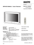
PT-92 16/9 Chassis Service Manual
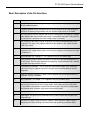
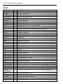
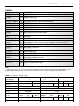
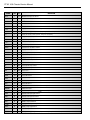
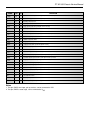
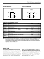
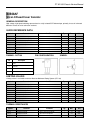
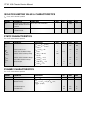
SYMBOL
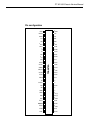
PIN
I/O
DESCRIPTION
PCLK
1
O
NICAM clock output at 728 Khz
NICAM
2
O
serial NICAM data output at 728 kHz
ADDR1
3
I
first I2C-bus slave address modifier
SCL
4
I
I2C-bus clock
SDA
5
I/O
I2C-bus data
VSSA1
6
supply
VDEC1
7
-
positive power supply voltage 1 decoupling; analog front-end circuitry
Iref
8
-
resistor for reference current generator; analog front-end circuitry
P1
9
I/O
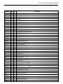
SIF2
10
-
sound IF input 2
Vref1
11
-
reference voltage; analog front-end circuitry
SIF1
12
I
sound IF input 1
ADDR2
13
I
second I2C-bus slave address modifier
VSSD1
14
supply
supply ground 1; digital circuitry
VDDD1
15
supply
digital supply voltage 1; digital circuitry
CRESET
16
-
capacitor for power-on reset
VSSD4
17
supply
supply ground 4; digital circuitry
XTALI
18
I
crystal oscillator input
XTALO
19
O
crystal oscillator output
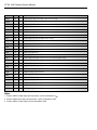
P2
20
I/O
SYSCLK
21
O
SCK
22
I/O
I2C-bus clock
WS
23
I/O
I2C-bus word select
SDO2
24
O
I2C-bus data output 2
SDO1
25
O
I2C-bus data output 1
SDI2
26
I
I2C-bus data input 2
SDI1
27
I
I2C-bus data input 1
TEST1
28
I
first test pin; connected to VSSD1 for normal operation
MONOIN
29
I
audio mono input
TEST2
30
I
second test pin; connected to VSSD1 for normal operation
EXTIR
31
I
external audio input right channel
EXTIL
32
I
external audio input left channel
SCIR1
33
I
SCART 1 input right channel
SCIL1
34
I
SCART 1 input left channel
VSSD3
35
supply
supply ground 3; digital circuitry
SCIR2
36
I
SCART 2 input right channel
SCIL2
37
I
SCART 2 input left channel
VDEC2
38
-
positive power supply voltage 2 decoupling; audio analog to digital converter circuitry
supply ground 1; analog front-end circuitry
first general purpose I/O pin
second general purpose I/O pin
system clock output