1
Group 28 Ignition systems
Design and fun ctio n
System descriptions
4
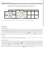
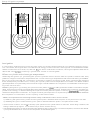
EZ -118K
EZ-118K
B200E, B230E and B230K
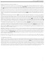
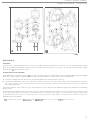
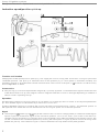
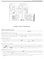
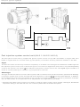
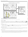
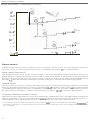
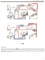
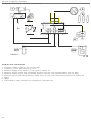
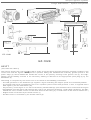
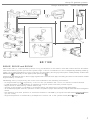
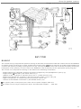
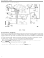
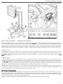
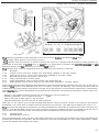
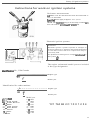
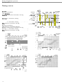
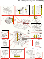
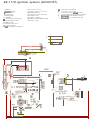
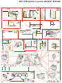
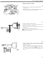
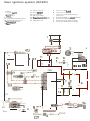
The con trol unit (11 computes the optimum timing on the basis of information from the various sensors and transmits the necessary ignition pu lses 10 the power stage /21. wh ich controls Ihe curren t in the primary winding of the ignition coil (3). The high-tension current induced in the secondary w inding by interruption of the primary is fed to the
distributor (4) for delivery to the appropri ate spark plug (5).
Variants for the B 230 K eng ine also supply signals to a solenoid valve (25) controlling the fuel cut-off function under
engine braking conditions.
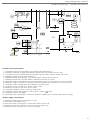
The timing selting compu ted by the con trol unit is based on the following information :
-
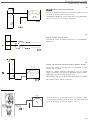
An engine load signal is supplied by a vacuum line (12) between the control unit and the intake manifold.
A Hall generator in the distributor (4) supplies an eng ine speed/crankshaft position signal.
Eng ine knock is indicated by a knock sensor (26).
Closure of the throttle is indicated by a throttle switch (19) mounted on the throttle cable pulley.
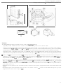
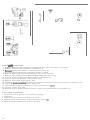
On models equipped with AC, operation of the compres sor (28) is indicated by a signal from the electromagnetic
clutch.
- The selection of a drive position on automatic models is indicated by a signal from the starting interlock switch
(27) via a relay.
- Engine temperature is measured by a temperature sensor (201 in the cylinder head (B 230 K only).
5'