1
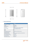
A065
L2 Service Manual
1. Technical Specifications
Particular
Key Matrix For Flashing
Chipset
Android Version
Frequency
Network Mode
ROM
RAM
Internal SD Card memory
Expandable Memory
Factory mode code
Remarks
N/A
MT6571
KITKAT 4.4.2
1.3GHz
GSM:900/1800
4GB
512Mb
NO
32GB
*#*#3646633#*#*
A065
L2 Service Manual
2. CAUTIONS
I. Flashing & Servicing must be undertaken by qualified personnel only.
II. Ensure all work is carried out at an anti-static workstation and that an anti-static wrist strap is worn.
III. Use only approved Tools & components as specified in the parts list.
IV. Ensure all components, modules, screws, and insulators are correctly re-fitted after servicing and
alignment
V. Ensure all cables and wires are repositioned correctly if Handset disassembled
VI. Electrostatic discharge can easily damage the sensitive components of electronic products. Therefore,
Service Centre must adhere the precautions which mentioned above.
3. L2 Level trouble shooting
1) Doesn’t Power On
NO.
Description
1
Doesn’t Power On
Reason
Soldering issue of sidekey
Sidekey broken
Mainboard issue
Solution
Re-soldering
Change the sidekey FPC
Refer to the L3 Repair
Check if the sidekey is
broken and then solder
issue.
A065
L2 Service Manual
2) LCD
NO.
1
2
Description
LCD segments missing, Fading,
Contrast issue, Black lines, Color issue,
Backlight issue, Blank display, Bad
pixel, Flickering.
LCD
Mechanically broken
Reason
LCD FPC assemble issue
LCD FPC broken
Mainboard issue
SW
LCD issue
LCD broken
Solution
Reassemble LCD FPC
Change the LCD
Refer to the L3 Repair
RE-FLASH THE SW
Change the LCD
Change the LCD
A065
L2 Service Manual
3) Touchpad
NO.
Description
1
TP not working and the light
perception issue.
2
TP Mechanically broken
Reason
FPC assembly
FPC broken
Mainboard
The light perception issue.
TP issue
TP broken
Solution
Reassemble the FPC
Change the TP
Refer to the L3 Repair
Change the TP
Change the TP
Change the TP
Take off the TP, and then check and test if it is working normally use the jig and fixture .
Test the mainboard if it is OK by the PCBA jig and fixture.
A065
L2 Service Manual
4) Charging
NO.
Description
1
No charging
2
Charging slow
Reason
Data cable issue
I/O connector
Charger issue
CPU
Data cable issue
I/O connector
CPU
<VCHG is poor soldering>
Solution
Change the data cable
Change the I/O connector
Change the charger
Refer to the service guide L3
Change the data cable
Change the I/O connector
Refer to the service guide L3
A065
L2 Service Manual
5) USB
NO.
Description
1
No charging
2
Cannot use DATA
Reason
Data cable issue
I/O connector
Charger issue
CPU
D+ or D- is broken
Solution
Change the data cable
Change the I/O connector
Change the charger
Refer to the service guide L3
Change the data cable
A065
L2 Service Manual
6) Main Camera/ Front Camera
NO.
1
2
3
4
Description
Reason
Connection issue
Camera not ready/not
Camera issue
working/no function
CPU
Front camera can’t
Camera issue
open
Rear camera can’t
Camera issue
open
Assemble issue
Camera issue
Bad image
CPU
Solution
Re-connecting
Change the camera
Refer to the service guide L3
Change the front camera
Change the front camera
Reassemble the camera
Change the camera
Refer to the service guide L3
Rear camera
Front camera
A065
L2 Service Manual
7) Vibrator
NO.
Description
1
No vibrating
Reason
Soldering issue
Vibrator issue
CPU
Assemble issue
Solution
Re-soldering the vibrator
Change the Vibrator
Refer to the service guide L3
Reassemble the vibrator
Vibrator
A065
L2 Service Manual
8) WI-FI/Bluetooth
NO.
Description
1
No signal
Reason
Solution
Wifi/BT antenna stand assembly
Reassemble
issue
Mainboard
Refer to the service guide L3
Antena stand
9) FM/Radio
NO.
Description
1
No signal
Reason
Solution
Earphone issue
Change a new earphone
Earphone Jack of mainboard
Refer to the service guide L3
issue
Earphone Jack
A065
L2 Service Manual
10) Ear Phone
NO.
Description
1
ONE SIDE
WORKING
Reason
earphone issue
IS
NOT
Cable broken
CPU or charging IC with issue
Cable broken
2
Noise
Cable broken
MIC issue
3
MIC is not working
4
Can’t end the call by
Assembly issue
earphone
Cable broken
Solution
Change a new earphone
open the housing of MIC, check
and solder the cable
Refer to the service guide L3
open the housing of MIC, check
and solder the cable
open the housing of MIC, check
and solder the cable
Change the earphone
open the housing of MIC, check
and solder the cable
Open the MIC housing ,check
and assembly again
Earphone
A065
L2 Service Manual
11) Outgoing Audio/Louder speaker
No.
Description
1
Noise/crack
2
No volume/low volume
Reason
The SPK with dust
Speaker foam issue
Speaker issue
CPU
Connection issue
Louder speaker issue
CPU
Solution
Clean the SPK
Change it
Change it
Refer to the service guide L3
Assembly it again
Change it
Refer to the service guide L3
Speaker
A065
L2 Service Manual
12) Incoming Audio / MIC
NO.
1
2
3
Description
Reason
There is dust with MIC
Solder issue
Noise with uplink side
MIC issue
The main LINK FPC assembly
issue
CPU or related component
There is dust with MIC
Solder issue
Volume low/no volume MIC issue
with uplink side
The main LINK FPC assembly
issue
CPU or related component
TDD noise
MIC issue
Solution
Clean the MIC
Re-solder it
Change the MIC
Reassemble the Link FPC
Refer to the service guide L3
Clean the MIC
Re-solder it
Change the MIC
Reassemble the Link FPC
Refer to the service guide L3
Change the MIC
MIC
A065
L2 Service Manual
13) Receiver
NO.
Description
1
Noise/crack
2
No voice/ volume low
Reason
There is dust with receiver
Receiver issue
CPU
Connection issue
Receiver issue
CPU
Solution
Clean the receiver
Change it
Refer to the service guide L3
Assembly it again
Change it
Refer to the service guide L3
Receiver
Thanks
For any Query or suggestion, Please write to [email protected]