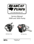
1
Service Manual
600R, 600V and 600B Pump
600R Rubber Pump
600V Virgin Pump
600B Crude Oil Pump
BearCat Pumps, LLC
(623)587-1350
1
Table of Contents
General Safety Precautions
Overview
3
4
Relief Valve
No-Leak Lip Seal
Installation
5
Shaft Alignment
System Piping
Piping Strain
Relief Valve
6
Relief Valve Setting
Start-Up
Routine Maintenance
7
8
Bearing grease for ‘R’ series pumps
Shaft Seal
Seal Replacement Procedure
Troubleshooting
9
No liquid delivered or the pump will not prime.
Pump noisy when operating
Technical Data
10
Maximum Operating Limitations
Model Number and Configuration
600R Parts Diagram / Dimensional Drawing
600V & 600B Parts Diagram / Dimensional Drawing
BearCat Pumps, LLC
(623)587-1350
11
12
14
2
GENERAL SAFETY PRECAUTIONS
• This manual should be read entirely prior to the commencement of installation and operation.
• Only qualified personnel should install, operate and maintain this pump and associated equipment.
• Check pump for specific safety warnings/labels.
• Prior to start-up, ensure complete cleanliness and integrity of the system in which the pump is
installed.
• In most cases the relief valve is factory set during performance test. In cases where the type of duty
is not known (such as distributors or stock orders) or where the components containing the relief
valve come from pre-tested stock batches, it is not possible to factory set the relief valve. In this
case it is the installers responsibility to set the relief valve in accordance with the specific
application.
• Pumps with heat tracing or jacketing necessary to prevent solidification of the product should be
brought up to working temperature prior to start-up.
• All electrical work must be done in accordance with the manufacturers recommended procedures by
qualified personnel.
• Ensure all guards are securely in place before operating the equipment. Do not remove guards at
any time during operation.
• For pumps operating under ‘flooded’ suction, when venting the pump through a plug or valve, care
should be taken not to completely remove vent plugs or completely open any vent as this could
result in liquid being discharged from the openings under pressure.
• Prior to start-up, ensure that the system valves and associated equipment are correctly set.
• Wear appropriate safety attire including long sleeves, face shield, and gloves, whenever starting or
operating the pump.
BearCat Pumps, LLC
(623)587-1350
3
OVERVIEW
The BearCat 600 is an external gear, positive
displacement pump designed
for
pumping asphalt. It is entirely heat jacketed with
relief valve in both
directions.
Three di erent models are available:
600V: Bronze bushing and shaft design. Works
well for standard asphalt and emulsions.
600R: AR Spherical Bearing design, rebuildable
pump. Ruggedized model designed for Asphalt/
Rubber.
Applications include: the primary pump of an Asphalt Distributor, Plant supply through a Micro
Coriolis (Mass Flow) meter, Blend transfer, or as an unloading pump.
600B: Bronze bushings, nitride shafts, hardened steel gears, works well with all grades of crude oil,
condensate, produced water, brine, iron sulfate and mixed byproducts.
Applications include: loading and unloading of crude oil transport trucks and trailers, fluid transfer for
tank battery, LACT units and refineries.
Relief Valve
One of the prominent features of the BearCat pump
is its endplate/relief valve design. The modularity of
the plate provides mounting on both ends of the
pump, and thus pressure relief in both directions.
Because the forward
is controlled by one end,
and the reverse
by the other, each can be
adjusted independently. The heat tracing o ers a
critically important
to start-up. Its balance
of heat in relation with that of the main body insure
full function of the relief valve prior to pump
rotation when full of asphalt.
No-Leak Lip Seal
The standard 600 comes with a high temperature, no-leak, low
maintenance seal design. Supported internally by a roller bearing,
the drive shaft runs precise, thus prolonging seal life.
Packed Seal available upon request. Graphite impregnated split ring
packing can be
if needed.
BearCat Pumps, LLC
(623)587-1350
4
INSTALLATION
Shaft Alignment
In the case of a belt driven system, care should be taken to insure proper alignment and tension of
the drive belts and pulleys. A pillow block must be used in order to support the side load from the
belts. Insure that the belts and pulleys are free and clean from oil and debris.
In the case of a direct drive system, proper care must be used to insure that the coupled shafts are
accurately aligned. Failure to do so may result in rapid wear of the seal and/or reduced pump life.
System Piping
Pump should be positioned as near as possible to source feeding it. Suction piping must be no
smaller in diameter than the pump intake port and designed to avoid sharp bends, changes in
sections or undue restrictions. Pressure drops due to an accumulation of valves, flex lines, etc can
be considerable and must be taken into consideration.
Certain designs such as a low level drop are designed in order to maintain a minimum amount of
liquid at the pump. After evacuating the lines, this remaining liquid can significantly improve
start-up priming.
Piping Strain
To ensure undue forces are not present, flange bolts (suction and discharge) should be completely
slackened. If flanges are observed to spring apart, twist or move out of parallel excessively,
remedial action must be taken.
The piping system can expand and contract considerably with the changes in temperature. Ensure
that the final system allows for this change.
BearCat Pumps, LLC
(623)587-1350
5
RELIEF VALVE
Each endplate can relieve the pressure in one
direction only. As such, if the valves are set in
opposing directions, each direction is
independently adjustable. So it is possible to
pressure relieve at 80 PSI in one direction, while
30 PSI in reverse. It is important for the operator
to understand which valve controls each
direction.
Caution:
A relief valve is necessary to protect the pump and
system from potentially dangerous over-pressure.
The relief valve will operate in the event of a restriction
in the discharge line or the inadvertent closure of a
downstream valve.
The valve must not be used as a flow control device.
Relief Valve Setting
V & R Series
If the pump is supplied without an internal relief valve,
a suitable external relief to the system must be supplied
The standard factory setting for the forward
in the pump is 80 psi. This is done by setting the
where the hex meets up with the threads of
the adjuster bolt
with the edge of the lock
nut. Backing the bolt out from this setting will
lower the pressure. Tightening it will increase
pressure at which the valve will open.
The internal relief valve will have been factory set.
However, check for correct operation upon installation.
Re-adjustment may be necessary due to viscosity
variations.
B Series
The standard setting for the 600B (Crude Oil) pump is 60 psi (four threads above the nut).
BearCat Pumps, LLC
(623)587-1350
6
START–UP
Caution:
1. Pump should turn freely by hand. Ensure all
guards are in place.
2. If heating is necessary, turn on supply and
allow pump temperature to stabilize.
3. Gradually open appropriate valves, and check
for signs of leakage.
Be sure all guards are in place, and all appropriate
safety gear is worn prior to starting pump.
During initial run, pump speed should be operated at
minimum in order to insure all functions are normal,
connections are leak free, and rotation is smooth.
Cautiously increase to normal operating speed.
4. If pump is above the level of liquid in the tank (suction lift), prime the pump by pouring a few
gallons of liquid (Do not use water) in the strainer housing or adjacent piping – particularly on the
suction side.
5. Check the pump rotation by flicking motor starter ‘on’ then ‘off’. (Correct rotation indicated by
diagram on pump cover plate)
6. Start pump – check system for leaks
BearCat Pumps, LLC
(623)587-1350
7
ROUTINE MAINTENANCE
Bearing grease for ‘R’ series pumps
For optimal service life in an R model pump, the bearings need one of two things prior to start-up
each day. Heat or Grease. Cold Asphalt Rubber (AR) is extremely tough on the bearings and castle
nut assembly inside the pump. If the pump is traced with heat transfer oil, then the bearing areas
will receive adequate heat that will soften the AR. However, if the pump is not traced the bearings
must be greased at the end of the day just after shut-down, but while the pump is still hot. Grease
with high temperature (Mystik JT-6). This will aide in lubricating the bearings and displacing/
diluting the AR prior to the next start-up.
Shaft Seal
After a period of time (based on pressure, operating procedures, material, etc) it will be necessary
to change the shaft seal. This is a fairly easy procedure. If the pump is leaking more than a drop a
minute, or any amount deemed unacceptable, insure the the a seal kit is on hand and follow the
seal replacement procedure;
Seal Replacement Procedure
1. Turn pump off completely.
2. Ensure that pump is isolated from system by closing
suction and discharge valves.
3. Remove any guards, couplings, bearings, or
companion flanges aft the dust seal (item 16). Remove
the dust seal bracket (item 16) and use a flat head screw
driver to pry out the old seal (item 15).
4. Clean the shaft surface and seal bore of any asphalt /
debris. Inspect and remove any sharp burrs in the
keyway and shaft body. Also inspect for groove worn
into shaft by the old seal. An excessively deep groove
will require shaft replacement.
5. Clear plastic tape can be used to mask keyway prior
to seal installation. Once the keyway is taped, lubricate
with grease. Gently slide main seal (item 15) over shaft, and into seal bore. Install new dust seal
bracket.
6. Replace guards, couplings etc.
BearCat Pumps, LLC
(623)587-1350
8
TROUBLESHOOTING
Under each fault symptom given below is a list of recommended inspections that could indicate the
cause, most are elementary but are often overlooked.
The best aid to fault finding in the pump is a vacuum gauge as close as possible to the pump inlet.
This can readily indicate whether the imposed suction is within the pumps capability, or if there has
been a dramatic change from the conditions, which will indicate a change in the viscosity of the
pumping media, resulting in higher pressure loss in the suction line, or that a filter requires
cleaning, etc.
No liquid delivered or the pump will not prime.
- Check Direction of shaft rotation.
- Are suction line joints leaking in air?
- Total suction condition, is there sufficient N.P.S.H. available?
- Has the pump been properly primed before start-up?
- Is suction port blocked? Is filter clean?
- All valves in system are open?
- Is the discharge line vented? Pressure build-up will ultimately prevent suction vacuum!
- If the vacuum gauge is reading over 20inHG there is almost certainly a blockage in the suction.
- Is the material hot enough? EVERYWHERE?
- If you have a screen box, add 3 gallons of suitable liquid to help establish prime.
Pump noisy when operating
- A low growling sound is normal for new pump. The noise is attributed to the meshing of the
hardened gears. The pump will tend to be louder when turning empty and will quiet down once
liquid prime is established.
- A loud clacking can be an indication that the pump is cavitating. Look for signs of inlet flow
restrictions or lower than normal material temperature. As a last resort, slow pump speed until
noise goes away.
- Pump internals are worn.
- Debris in material. Add screen box.
- Misalignment of drive system.
BearCat Pumps, LLC
(623)587-1350
9
TECHNICAL DATA
Maximum Operating Limitations
Pressure: 130 PSI (9 BAR)
Speed: 500 RPM
Temperature:
Actual
can be limited by any number of parameters. Line
restrictions, viscosity, material
type etc. The standard maximum RPM is based on ideal conditions. As a general rule, we
recommend reducing speed RPM limits by 25% when handling viscous materials such as rubberized
asphalt.
When certain conditions are met, the pumps may be used in excess of the limitations. Please consult
factory for high performance parameters exceeding standard
Horse Power (Hp)
600
500
400
300
200
100
0
V & R Series
B Series
Flow Rate - GPM
Flow Rate (GPM)
Pump Graphs
0
This graph is generalized. Flow rate will vary,
with material and conditions.
150 300 450 600
Pump Speed (RPM)
750
Power (neglecting viscosity)
20
25 PSI
50 PSI
100 PSI
15
10
5
0
0
100
200
300
Pump Speed (RPM)
BearCat Pumps, LLC
(623)587-1350
400
500
10
MODEL NUMBER AND CONFIGURATION
B= Crude Oil, bronze bushing
BearCat Pumps, LLC
(623)587-1350
11
600R PARTS DIAGRAM / DIMENSIONAL DRAWING
To order specify model number
(ex - 600RMX) followed by item;
(1) Housing
(2) Gear Set
(3) End Plate Gasket
(4) Idler Shaft
(5) Drive Shaft
(6) End Plate
(7) Adjuster Nut
(8) Adjuster Nut O-ring
(9) Relief Valve Assembly
(10) O-ring RV plate
(11) Bearing Cap
(12) O-ring Cover Plate
(13) Steel Sleeve
Continued
(17) Castle Nut and Cotter Pin
(18) Bearing
Heat fittings. All tapped ports require a
#12 O-ring Fitting. DO NOT USE
PIPE THREAD FITTINGS!
(20) #12 MB O-ring Plug
(21) #12 MB O-ring Straight
(22) J-tube
(23) #12 MB O-ring Elbow
Modified Lip Seal
(14) Seal Housing
(15) Shaft Seal
(16) Dust Seal/Mount Bracket
Hardware items can be obtained from
a local hardware store.
(A) 3/8 Key stock 2” Lg
(B) 1/2 Dowel pin 1-1/4” Lg
(C) 3/8-16x3/4 Socket Head
(D) 1/4-20x3/8 Socket Head
(E) 3/8-16x1/2 Set Screw
(F) 3/8-16x1-1/2 Socket Head
BearCat Pumps, LLC
(623)587-1350
12
Port Size
- Both ports are a 3” ANSI 150# Pipe flange.
- For high performance requirements, consult factory for weld on flanges for 4” pipe. With this
set-up, the pump and entire pipe system are now 4” throughout.
BearCat Pumps, LLC
(623)587-1350
13
600V & 600B PARTS DIAGRAM / DIMENSIONAL DRAWING
To order specify model number
(ex - 600VMX) followed by item;
(1) Housing
(2) Gear Set
(3) End Plate Gasket
(4) Idler Shaft
(5) Drive Shaft
(6) End Plate
(7) Adjuster Nut
(8) Adjuster Nut O-ring
(9) Relief Valve Assembly
(10) O-ring RV plate
(11) Bearing Cap
(12) O-ring Cover Plate
(13) Bushing
Modified Seal
(14) M24/Housing Assembly
(15) Shaft Seal
(16) Dust Seal and Mount
Bracket
Heat fittings. All tapped ports require a
#12 O-ring Fitting. DO NOT USE
PIPE THREAD FITTINGS!
(20) #12 MB O-ring Plug
(21) #12 MB O-ring Straight
(22) J-tube
(23) #12 MB O-ring Elbow
Packed Seal (not shown in drawing)
(17) 9-Ring Packing Set
(18) Packing Gland (2 pc)
(19) Studs/Clips/Washers/Nut (2)
Hardware items can be obtained from
a local hardware store.
(A)
(B)
(C) 3/8-16x3/4 Socket Head
(D) 1/4-20x3/8 Socket Head
(E) 3/8-16x1/2 Set Screw
BearCat Pumps, LLC
(623)587-1350
14
Port Size
- Both ports are a 3” ANSI 150# Pipe flange.
- For high performance requirements, consult factory for weld on flanges for 4” pipe. With this
set-up, the pump and entire pipe system are now 4” throughout.
BearCat Pumps, LLC
(623)587-1350
15