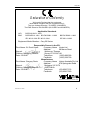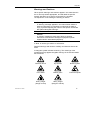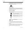
1
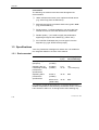
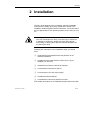
Cary 50 Hardware Operation manual Installation Category I Pollution Degree 2 Safety Class 3 (EN61010-1) Publication No. 85 10159600 June 1999 Cary 50 Varian offices Varian has offices in most countries. The major offices for optical spectroscopy products are listed below: Varian Australia Pty Ltd (Manufacturing site) 679 Springvale Road Mulgrave, Victoria 3170 Australia International telephone: + 61 3 9560 7133 International fax: + 61 3 9560 7950 Varian Instruments 2700 Mitchell Dr. Walnut Creek, CA 94598 USA Phone:1 800 926 3000 International telephone: +1.925.939.2400 International fax:+1.925.945.2102 Varian Chrompack Benelux Analytical Instruments Boerhaaveplein 7, 4624 VT Bergen op Zoom Postbus 250, 4600 AG Bergen op Zoom, Netherlands International telephone: +31 0164 282800 International fax: +31 0164 282828 Internet The Varian Internet home page can be found at: http://www.varianinc.com Varian Australia Pty Ltd is the owner of copyright on this document and any associated software. Under law, the written permission of Varian Australia Pty Ltd must be obtained before either the documentation or the software is copied, reproduced, translated or converted to electronic or other machine-readable form, in whole, or in part. First published 1997 in Australia. Updated Feb, June 1999. Comments about this manual should be directed to the Marketing Communications Manager, Varian Australia at the address above or by Email to [email protected]. Varian Australia is ISO9001 certified. © 1997 Varian Australia Pty Ltd (A.C.N. 004 559 540) All rights reserved ii Publication date: 06/99 Cary 50 Declaration of Conformity We hereby Declare that the equipment listed below complies with the requirements of:The Low Voltage Directive 73/23/EEC (93/68/EEC) The EMC Directive 89/336/EEC (92/31/EEC and 93/68/EEC) Applicable Standards LVD EMC BS EN 61010-1:1993 BS EN55011:1991 BS EN 50081-1:1992 BS EN 50082-1:1992 IEC 801-2:1991 IEC 801-3:1984 IEC 801-4:1988 Equipment Model Number Cary 50 Series Responsible Person in the EU. Print Name: W. David Lowe Company Name Varian Ltd Address 28 Manor Road Signed: Walton-on-Thames Position: Managing Director Surrey KT12 2QF UK Date: 25-08-97 Telephone (1932) 898 000 Facsimile (1932) 228 769 Manufacturer Print Name: Gregory Davis Company Name Varian Australia Pty Ltd Address 679 Springvale Road Signed: Mulgrave VIC 3170 Position: Managing Director AUSTRALIA Date: 25-08-97 Telephone (03) 9560 7133 Facsimile (03) 9560 7950 Publication number 85 101595 00 08/97 Publication date: 06/99 iii Cary 50 This page is intentionally left blank iv Publication date: 06/99 Cary 50 Table of Contents Safety practices and hazards 1 vii Introduction 1-1 1.1 Installation requirements 1-1 1.2 Cary documentation 1-1 2 1.3 Specifications 1.3.1 Environmental 1.3.2 Personal computer 1.3.3 Connections 1.3.4 Weights and dimensions Installation 1-2 1-2 1-3 1-3 1-3 2-1 3 2.1 Cell holder 2.1.1 Installation 2.1.2 Alignment 2.1.3 Other sample holders Maintenance 2-2 2-3 2-3 2-4 3-1 3.1 Cleaning 3-1 3.2 Lamp module 3.2.1 Lamp module replacement 3.2.2 Aligning the source mirror Troubleshooting 3-2 3-2 3-5 4-1 4 4.1 Installing a Cary 50 under Windows NT 4-1 4.1.1 Windows NT service or driver failure 4-2 4.1.2 Access denied 4-5 4.1.3 Fcary service failed to start 4-6 4.1.4 There is no green light indicating that the Cary 50 is powered. 4-7 4.1.5 Start button replaced with Connect button 4-7 4.1.6 Hard disk power supply connection 4-8 4.1.7 The Absorbance is 10 Abs and fluctates wildly during a scan. 4-9 4.1.8 Windows 95/98 Input/Output hardware conflict 4-9 4.1.9 No free Interrupt request 4-10 Publication date: 06/99 v Cary 50 4.2 Instrument performance testing 5 vi 4-11 4.3 Un-installing the Cary 50 driver 4-12 4.4 Un-installing the WinUV software 4-13 Spare parts 5-1 Publication date: 06/99 Cary 50 Safety practices and hazards Your Varian Cary instrument and accessories have been carefully designed so that when used properly you have an accurate, fast, flexible and safe analytical system. If the equipment is used in a manner not specified by the manufacturer, the protection provided by the equipment may be impaired. Information on safety practices appears throughout the documentation (both hard copy and on-line) provided with your instrument and accessories. Before using the instrument or accessories, you must thoroughly read these safety practices. Observe all relevant safety practices at all times. Lamp module The lamp is enclosed in a self-contained module. This module contains components operating at high voltages. To avoid electric shock, NEVER disassemble the module. When operating, the lamp module emits high intensity light which can cause serious damage to eyes. To avoid eye damage, never operate the lamp outside the instrument. Electrical hazards The Cary 50 is powered by the personal computer (PC) controlling the instrument. The safe operation of the instrument depends on the integrity of the switching power supply of the PC. Your PC must comply with IEC 60950. Publication date: 06/99 vii Cary 50 Panels, covers and modules The only module you are permitted to remove is the lamp module (on the underside of the instrument). The screws you need to undo to remove this module are indicated by white circles. The only panel you are permitted to remove is the snap out panel covering the lamp mirror adjustment screws on the front of the instrument. Any other panels or covers which are retained by screws on the spectrophotometer and accessories may be opened ONLY by Varian-trained, Varian-qualified, or Varian-approved service engineers. Consult the manuals or product labels supplied with your PC, monitor and printer/plotter to determine which parts are operator-accessible. Operators and other unauthorized personnel are permitted access ONLY to the lamp module and the sample compartment of the Cary. ALWAYS switch off the PC before changing a lamp. Note that the safety classification is given as Class 3 (EN 61010-1). Other precautions Do not block any ventilation grills present on the PC. Consult the manuals supplied with your PC, monitor and printer/plotter for their specific ventilation requirements. Use of the Cary system and accessories may involve materials, solvents and solutions which are flammable, corrosive, toxic or otherwise hazardous. Careless, improper, or unskilled use of such materials, solvents and solutions can create explosion hazards, fire hazards, toxicity and other hazards which can result in death, serious personal injury, and damage to equipment and property. ALWAYS ensure that laboratory safety practices governing the use, handling and disposal of such materials are strictly observed. These safety practices should include the wearing of appropriate safety clothing and safety glasses. viii Publication date: 06/99 Cary 50 Warnings and Cautions Other specific warnings and cautions appear in this manual and in the on-line help where appropriate, and will detail the specific hazard, describe how to avoid it, and specify the possible consequences of not heeding the warning or caution. Warning A ‘Warning’ message appears in the manual when failure to observe instructions or precautions could result in death or injury. Symbols depicting the nature of the specific hazard are also placed alongside warnings. Caution A ‘Caution’ message is used when failure to observe instructions could result in damage to equipment (Varian supplied and/or associated equipment). A ‘Note’ is used to give advice or information. Read all warnings and cautions carefully and observe them at all times. A triangular symbol indicates a warning. The meanings of the symbols that may appear alongside warnings in the documentation are as follows: Publication date: 06/99 Electrical shock Eye hazard Noxious gases Fire hazard Broken glass Corrosive liquids Heavy weight (danger to feet) Heavy weight (danger to hands) ix Cary 50 The following symbol may be used on warning labels attached to the instrument. When you see this symbol you must refer to the relevant operation or service manual for the correct procedure referred to by that warning label. Power indicator The green indicator lamp on the front of the Cary 50 indicates the instrument is powered up (i.e. the PC is switched on) and is in normal/standby condition. When the indicator lamp is flashing this indicates the instrument is busy. Information symbols The following symbols appear on the Cary 50 to provide you with additional information: Attached to the rear of the product, and indicates that the product complies with the requirements of one or more EU Directives Attached to the rear of the product, and indicates that the product has been certified (evaluated) to CSA 1010.1 and UL 3101-1. Indicates high voltage Xenon flash lamp present Xe Indicates viewing hole to check the operation of the Xenon flash lamp Federal Communications Commission advisory The following is a Federal Communications Commission advisory: Caution This equipment generates, uses, and can radiate radio frequency energy and if not installed and operated in accordance with the instruction manual, may cause interference to radio x Publication date: 06/99 Cary 50 communications. It has been tested and found to comply with the limits for a Class A computing device pursuant to Subpart J of Part 15 of FCC Rules, which are designed to provide reasonable protection against such interference when operated in a commercial environment. Operation of this equipment in a residential area may cause interference in which case the user at his or her own expense will be required to take whatever measures may be required to correct the interference. CE Compliant Products Cary instruments have been designed to comply with the requirements of the Electro-magnetic Compatibility (EMC) Directive and the Low Voltage (electrical safety) Directive (commonly referred to as the LVD) of the European Union. Varian has confirmed that each product complies with the relevant Directives by testing a prototype against the prescribed EN (European Norm) standards. Proof that a product complies with the Directives is indicated by:❑ the CE Marking appearing on the rear of the product ❑ the documentation package that accompanies the product containing a copy of the Declaration of Conformity. This Declaration is the legal declaration by Varian that the product complies with the Directives, and also shows the EN standards to which the product was tested to demonstrate compliance. It is also signed by Varian's Authorized Representative in the EU, and by the representative of the manufacturing plant. Publication date: 06/99 xi Cary 50 This page is intentionally left blank. xii Publication date: 06/99 Cary 50 1 Introduction 1.1 Installation requirements Prior to receiving your instrument you will have been provided with a Cary Pre-installation manual, which describes the environmental and operating requirements of the Cary system. You must prepare your laboratory according to these instructions before the Cary can be installed. You should keep the Pre-installation manual for future reference. If you have misplaced your copy, you can obtain a replacement from your local Varian office. 1.2 Cary documentation You have been provided with the following documentation to help you set up and operate your Cary 50 system: Publication date: 06/99 ❑ Installation Guides (one for each operating system supported), with information on unpacking the instrument, installing the interface card in the PC and setting up the system ❑ This operation manual, with Safety practices and hazards information, instructions for installing and maintaining the components of the Cary 50, and troubleshooting information ❑ Cary WinUV software manual, with instructions for installing the Cary WinUV software, an overview of the software and software related troubleshooting information ❑ Extensive on-line Help (provided with the Cary WinUV software) containing context-sensitive help, step-by-step instructions for frequently performed analyses and instructions for using any accessories you ordered. 1-1 Cary 50 Conventions The following conventions have been used throughout the documentation: ❑ Italics indicate menu items, menu options and field names (e.g. select Copy from the Edit menu). ❑ Keyboard and mouse commands have been typed in bold (e.g. press the F2 key). ❑ Single quotes (‘ ’) indicate a selection you can make from several choices, such as radio buttons and checkboxes. ❑ Double quotes (“ ”) are used to signify the pushbuttons appearing throughout the software (e.g. select “OK”). ❑ ALL CAPITALS indicates text you must type in from the keyboard (e.g. type SETUP at the prompt). 1.3 Specifications Your Cary instrument is designed for indoor use. It is suitable for the categories stated on the front of this manual. 1.3.1 Environmental Condition Altitude Temp t (°C) Humidity (%RH) non-condensing Non-operating (transport) 0-2133 m (0-7000') 5-45 20-80 Operating but not necessarily meeting performance specifications 0-2000 m (0-6562') 5-31 31-40 ≤80 ≤{80-3.33(t-31)} Operating within performance specifications 0-853 m (0-2800') 10-35 8-80 853-2133 m (2800-7000') 10-25 8-80 For optimum analytical performance it is recommended that the ambient temperature of the laboratory be between 20-25 °C and be held constant to within ±2 °C throughout the entire working day. 1-2 Publication date: 06/99 Cary 50 1.3.2 Personal computer To ensure safe operation of the instrument, the switching power supply in the PC must comply with standard IEC 950 or equivalent. PC power supply The power requirements of the Cary 50 must be met by the PC power supply and the following capacity (in addition to what is required by the PC itself) is required: +5V DC <1 A +12V DC <1.5 A -12V DC <0.25 A, a total of 26 W for the instrument. Allowance must also be made for external accessories powered by +12V DC. Operating motor driven accessories will increase the +12 V current by a further 2 A (a maximum of 24 W for accessories). Varian recommends a PC power supply rating of 220 W as a minimum. 1.3.3 Connections 3.5 mm phono jack socket in the left hand side of the sample compartment for accessories. 8-pin DIN connector in the left hand side of the sample compartment for the diode detector. 25-pin D-range connector in the right hand side of the sample compartment for accessories (optional). 1.3.4 Weights and dimensions Weight Packed 23 kg (50.7 lb) Unpacked 21 kg (46 lb) Dimensions (W x D x H) Packed 615 x 710 x 360 mm (24 x 28 x 14 in) Unpacked Publication date: 06/99 590 x 500 x 200 mm (23 x 20 x 8 in) 1-3 Cary 50 This page is intentionally left blank 1-4 Publication date: 06/99 Cary 50 2 Installation The Cary 50 is designed to be completely customer-installable. Instructions for setting up the Cary system are included in the Installation Guides supplied with the instrument. You should select the one appropriate for the operating system you are using on your PC. Warning The Cary 50 weighs over 20 kg. To avoid injury to personnel or damage to equipment, always use two or more people when lifting or carrying the instrument. NEVER attempt to lift the instrument alone. Following the instructions in the Installation Guide you should have: ❑ Unpacked the spectrophotometer and placed it on the intended workbench ❑ Installed the instrument interface card in the PC (if you supplied your own PC) ❑ Installed the Accessory Cable kit (if ordered) ❑ Connected the instrument to the PC ❑ Connected the PC to the power supply ❑ Installed the WinUVsoftware ❑ Completed the instrument performance tests. This chapter describes how to install the sample holders used with Publication date: 06/99 2-1 Cary 50 the Cary 50. Instructions for installing/replacing the lamp module are included in the next chapter. 1 2 Cary 50 showing the sample compartment lid (1) and front panel (2) 2.1 Cell holder A microcell holder is supplied as standard with the Cary 50. Follow the instructions below to install and align it. Cell holder base (left) and Microcell Holder 1. Locating holes 2. Cell holder base thumbscrew 3. Cell lifter 2-2 4. Microcell holder thumbscrew 5. Adjustment screw 6. Hexagonal ball driver Publication date: 06/99 Cary 50 2.1.1 Installation To install the microcell Holder: 1. Place a microcell in the microcell Holder (if the cell has ground glass sides or sides featuring the Cary logo, hold the cell by these sides) and check that the cell aperture is vertically centred in the cell holder aperture. 2. If the cell aperture is not at the correct height, remove the cell and adjust the grub screw in the Microcell Holder accordingly using the hexagonal ball driver (2.5 mm). Replace the cell in the Microcell Holder. 3. Slide back the sample compartment lid. 4. Remove the sample compartment front panel. 5. 5. If not already fitted, install the cell holder base in the sample compartment as follows: a. Place the cell holder base in the sample compartment, aligning the two locating holes over the two locating pins in the floor of the sample compartment. b. Firmly tighten the thumbscrew on the cell holder base (item 2 in picture above). 6. Place the Microcell Holder on the cell holder base, aligning the holes in the Microcell Holder over the raised black knobs in the cell holder base. 7. Tighten the thumbscrew on the Microcell Holder. You should now align the Microcell Holder. 2.1.2 Alignment To align the Microcell Holder: 1. Start the Align application by pressing the ‘Start’ button in the Windows Taskbar and selecting Programs, Cary WinUV, Align. 2. Select the Cary tab. 3. In the Instrument Parameters group, set the wavelength to 0 nm (white light) by enabling the Zero Order checkbox. 4. Press ‘Apply’. (The green power indicator on the instrument should start flashing to indicate that the instrument is active.) Publication date: 06/99 2-3 Cary 50 5. Place a cell in the Microcell Holder (if you have not already done so). 6. Place a small piece of white paper in the light path to the right of the cell. If the beam appears as though it will strike the cell aperture, move the paper to the left of the cell and check that the beam is passing through the cell. (If the beam does not appear as though it will pass through the cell, adjust the height of the cell as described in 2.1.1.). 7. Using the hexagonal ball driver (2.5 mm), adjust the Microcell Holder adjustment screw (item 5 in picture above) and note the intensity of the light striking the paper. Continue to adjust the adjustment screw until the beam hitting the paper appears the most intense. ✒ Note You may need to dim the room lights to see the light beam. 2.1.3 Other sample holders Other sample holders are available for use with the Cary 50, such as the Solid Sample Holder. Instructions for their use are included in the on-line help provided with the Cary WinUV software. Refer to the Cary WinUV manual (part number 85 101625 00) for details on using the on-line help. 2-4 Publication date: 06/99 Cary 50 3 Maintenance This chapter includes the maintenance procedures for the Cary 50 that may be carried out by an operator. Any maintenance procedures not specifically mentioned in this chapter should be carried out only by Varian-trained, Varian-qualified or Varianauthorized service engineers. Warning This instrument contains an intense light source. Direct viewing of the light source will cause eye damage. Operators and other unauthorized personnel must NEVER remove the main cover. ✒ Note This section refers only to maintenance procedures for the Cary spectrophotometer. You should refer to your PC and printer manuals for their maintenance procedures, and to the Cary WinUV on-line help for the maintenance procedures for any Cary accessories you ordered. 3.1 Cleaning Any spills in the sample compartment should be wiped up immediately. The exterior surfaces of the Cary spectrophotometer should be kept clean. All cleaning should be done with a soft cloth. If necessary, this cloth can be dampened with water or a mild detergent. Do not use organic solvents or abrasive cleaning agents. Publication date: 06/99 3-1 Cary 50 3.2 Lamp module This section describes how to replace the lamp module and realign the light beam. Before changing the lamp module, ALWAYS disconnect the Cary 50 from the PC. ✒ Note These instructions are also provided on-line with the Cary WinUV software, together with video to demonstrate the procedure. Refer to the Cary WinUV manual (publication number 85 101625 00) for details on using the on-line help. 3.2.1 Lamp module replacement Warning When operating, the lamp module emits high intensity light which can damage eyes. To avoid eye damage, never operate the lamp module outside the instrument. The lamp module contains components operating at high voltages. To avoid electric shock, NEVER disassemble the lamp module. To remove the lamp module: 1. Remove the plug from the ‘inst’ connector on the rear panel of the Cary 50. 2. Turn the Cary onto its side to give access to the base. 3-2 Publication date: 06/99 Cary 50 Underneath the Cary 50 – 6 screws to remove are marked here. 3. Undo and remove the six screws marked by the white solid circles on the lamp module cover using a star head screwdriver. As you remove the last screw, use one hand to support the lamp module. Publication date: 06/99 3-3 Cary 50 4. Hold the lamp module out from the instrument and unplug the 3 pin connector from the Cary 50. Discard the lamp module. To fit a new lamp module: 1. Plug the 3 pin connector of the new lamp module into the instrument. 2. Fit the lamp module in the base of the Cary 50, ensuring that the wiring is kept clear of the other parts of the instrument. 3. Replace and tighten the six screws. 4. Return the instrument to its upright position and replace the cable at the rear. 5. Reconnect the PC to the Cary 50. 3-4 Publication date: 06/99 Cary 50 3.2.2 Aligning the source mirror For optimum performance of the instrument, the source mirror should be aligned to suit the new lamp module. To align the source mirror: 1. Start the Align application by pressing the “Start” button in the Windows Taskbar and selecting Programs, Cary WinUV, Align. 2. On the Cary tab set the following parameters:: (a) Single beam mode, Normal Publication date: 06/99 (b) Y Mode %T (c) Ave Time 0.5000 (d) Wavelength 500 nm 3-5 Cary 50 ✒ Note 3. Press “Apply”. 4. Remove the snap-out panel (see below) from the front of the instrument, using a flat blade screwdriver to pry the panel open. This exposes the two source mirror adjustment screws. Do not remove the plastic bung next to the adjustment screws. 1. The snap-out panel (1) on the front of the Cary 50 5. ✒ 3-6 Note On the Lamps tab (see figure below), monitor the Current Signal bar as you use the supplied hexagonal balldriver (2.5 mm) to slowly adjust one of the adjustment screws at the front of the instrument. If the length of the Current Signal bar decreases, slowly turn the screw in the other direction. (You can expect to see some fluctuation due to noise). If the signal is out of range or excessively weak or strong, press “Rescale” to bring the signal back into range for display. Continue to adjust the screw until the length of the Current Signal bar is maximized. When the length of the Current Signal bar is at its greatest, repeat for the other adjustment screw. It does not matter in which order the adjustment screws are aligned. Publication date: 06/99 Cary 50 Align window 5. Replace the snap out panel on the front of the instrument. The source mirror is now aligned and the instrument is ready for use. Publication date: 06/99 3-7 Cary 50 This page is intentionally left blank 3-8 Publication date: 06/99 Cary 50 4 Troubleshooting This chapter contains troubleshooting information to help you solve various problems you may encounter when setting up or using your Cary 50 hardware. 4.1 Installing a Cary 50 under Windows NT Windows NT 4 is not Plug and Play. However it will report initialization failures of device drivers loaded during NT startup. Make sure that you have completed all the following steps for an installation of the Cary 50 under Windows NT. ✒ Note Install Service pack 4 or greater Install Microsoft’s Internet Explorer 4.0 or later Shut down Windows NT Restart the PC Ensure that all devices within the system have drivers installed and that the devices are operational. eg. Sound cards produce sound, SCSI cards allow access to drives. If another hardware device is installed the device drivers should be installed prior to installation of the WinUV software Some PC’s have hardware built into the motherboard (eg. Sound cards, Network adapters (NIC) etc. If you wish to use devices other than those available on the mother board you must disable the motherboard devices in the system BIOS (consult your PC documentation). This will free the device resources (ie. IRQ and I/O address space). Publication date: 06/99 Install Windows NT 4.01 or an NT foreign language version. Follow the Start here Windows NT guide (supplied with the Cary instrument) to install the Cary 50 PC card. Restart Windows NT 4-1 Cary 50 Log on with Administrator rights and privileges. If you are unable to logon with administration rights installation of hardware device drivers and associated registry entries will not be completed. You will see the following warning during the Cary WinUV software installation. Speak to your system administrator about your access rights or have him/her install the Cary WinUV software for you. Install the WinUV software 4.1.1 Windows NT service or driver failure Problem When you start NT 4.0 you see the following message: Solution 1 1. Click on the Windows NT Start button and select Programs, Administrative tools, Event Viewer. 2. Find the hardware device driver that failed to load during startup event (indicated by a red STOP on the left hand side). 4-2 Publication date: 06/99 Cary 50 3. Double click on the failed event to determine the cause of the failed device. If it was the Cary 50 that failed to load you will see the following description: Publication date: 06/99 4-3 Cary 50 4. This generally means that the device driver loaded but there was no response from the Cary 50 instrument. This indicates that the Cary 50 interface hardware is not responding. 5. Ensure that the Cary 50 card is installed correctly and that the interconnecting cable is secure. Solution 2 Another cause of this error may be due to a conflict between the Cary 50 driver and another driver on the system. This is more likely to happen on a Windows NT system. The most common cause is a sound card for which a driver has not been installed. The PC may have a sound card built into the motherboard as well as a separate sound card which the PC recognizes but doesn’t have a driver installed for. You will need to: 1. Un-install the Cary WinUV software (refer to 4.4). 2. Un-install the Cary 50 driver by referring to section 4.3. 3. Click Start, Settings, Control Panel, Multimedia (for a NT system) or System (for a Win 95 or 98 system). Select the Devices tab (NT) or Device Manager tab (Win 95/98). 4-4 Publication date: 06/99 Cary 50 4. If you see a ! mark next to one of the devices you need to fix the problem (usually by installing the latest driver) before installing the Cary 50 driver and WinUV software. 4.1.2 Access denied Problem During the installation of the WinUV software you may see the following message: Publication date: 06/99 4-5 Cary 50 Solution You must be logged on with administrator rights to install the WinUV software. Click on the Windows NT Start button, select Shutdown and then Close all programs and log on as a different user. When prompted, log on as an Administrator or ask your NT Administrator to log on for you. Start the WinUV installation process again. 4.1.3 Fcary service failed to start Problem After the installation of the WinUV software the following message is displayed: Solution This indicates the Cary 50 device driver was not copied to the correct directory. It is possible you may not have access rights to the installation drive. Logon with administration rights (refer to 4.1.2 ) and perform the Cary WinUV installation again. 4-6 Publication date: 06/99 Cary 50 4.1.4 There is no green light indicating that the Cary 50 is powered. The Cary 50 is powered directly from the PC power supply. A green power indicator light on the front of the Cary 50 indicates when the instrument is powered. Problem The power indicator on the Cary 50 does not light when the PC is switched on. Solution Check the connection of the main instrument cable connecting the PC to the Cary 50. If the power indicator on the front of the Cary 50 is still not on, check the connection of the PC power supply connector to the Cary 50 card inside the PC. Instructions for the connection of the power supply connector are listed in the Installation Guide supplied with your Cary 50 (and in section 4.1.6 if you need to use a Y connector). 4.1.5 Start button replaced with Connect button Problem I have a ‘Connect’ button instead of a ‘Start’ button. What does this mean? Answer Only one Cary application can communicate with the instrument at a time. When you turn the PC on the System information application initializes the Cary 50 and checks that it is working correctly. If you start another application e.g. Scan before this initialization has finished the application will have a ‘Connect’ button instead of a ‘Start’ button. Just wait for the status line at the bottom of the application to display ‘idle’ and then click on the Connect button and it will change to a Start button. Problem The Connect button will not change to Start. Answer If the Cary software cannot locate the Cary 50 PC card then the Connect button will not change to Start. This is due to either: • Publication date: 06/99 A memory address conflict with the Cary 50 PC card and another card in the PC. 4-7 Cary 50 • An IRQ conflict with another card • An I/O address conflict with another card. • A defective IEEE or Cary 50 PC card. Under Windows NT the best way to fix the problem is to: 1. Remove as many other cards from the PC as possible e.g. sound or network card, de-installing their drivers as well. 2. De-install the Cary driver (refer to 4.3) 3. Re-boot the PC. 4. Re-install the Cary software. 5. Check that the PC is now communicating with the Cary instrument (the Connect button should change to Start when you click on it). 6. Re-install the other cards, specifying another IRQ and/or memory address if possible. If you can’t change these then you may have to purchasedifferent cards which allow more flexibility in changing the IRQ and/or memory address. 4.1.6 Hard disk power supply connection Problem There is not a spare hard disk power supply connector in the PC to connect to the Cary 50 PC card. Solution With the Disposable Grounding Wrist Strap (supplied with the Cary 50) fitted, plug the appropriate end of the supplied Y connector (see figure below) into the connector at the end of the Cary 50 PC card. Unplug a hard disk power supply connector and connect it to the Y connector. Connect the free end of the Y connector to the hard disk. Y connector supplied with the Cary 50 4-8 Publication date: 06/99 Cary 50 4.1.7 The Absorbance is 10 Abs and fluctates wildly during a scan. Problem The Cary 50 is reporting 10 Abs and a scan like that shown below is displayed on the screen: Solution The detector cable inside the Cary 50’s sample compartment is not connected. Check that the 8 pin plug at the back of the left hand side of the sample compartment is plugged in firmly. 4.1.8 Windows 95/98 Input/Output hardware conflict Problem A warning message regarding device conflicts appears when you start the PC after installing the Cary 50 Hardware device driver. This occurs when one (or more) device in the system tries to use the same Input/output resource. Solution Reboot the PC. If the message still appears it will be necessary to change the I/O address used by the conflicting device, since the I/O address of the Cary 50 PC card is fixed at 0210 - 021F. To change the I/O address of the conflicting device: 1. Press “Start” in the Windows Taskbar. 2. Select Settings/Control Panel/System. Publication date: 06/99 4-9 Cary 50 3. Select the Device Manager tab. 4. Expand ‘Other devices’ and select Varian Cary 50. The conflicting device will appear in the Conflicting device list. Press “Cancel’ to return to the Device Manager tab. 5. Locate the conflicting device in the list and double click on it. 6. On the Resources tab, deselect ‘Use automatic settings’ and change the Input/Output address until the message “No Conflicts” appears in the Conflicting device list. 4.1.9 No free Interrupt request Problem There is not a spare Interrupt request available for the Cary 50. Solution Disable a device which you do not use frequently, for example a sound card. To disable the device: 1. Press “Start” in the Windows Taskbar. 4-10 Publication date: 06/99 Cary 50 2. Select Settings/Control Panel/System. 3. Select the Device Manager tab. 4. Double click on the device you want to disable. 5. On the General tab, disable the ‘Original Configuration’ checkbox. 4.2 Instrument performance testing Problem The results of your instrument performance tests do not meet specifications (the results obtained during factory testing are included in the packing crate with the instrument). Solution Check the following: ❑ Publication date: 06/99 The sample compartment is empty. 4-11 Cary 50 ❑ The cable connecting the instrument to the PC is correctly connected and the retaining screws are tightened. ❑ The lamp is pulsing during initialization. This is indicated if the green power indicator on the front of the instrument flashes (you should also hear the monchromator and the filter wheel moving). You should also turn the instrument on its side and look through the small lamp viewing hole in the base of the instrument. If the lamp is not pulsing you may have a hardware conflict (see sections 4.1.8). ❑ The lamp is correctly aligned (refer to Chapter 3 for instructions on aligning the lamp). Warning When operating, the lamp module emits high intensity light which can damage eyes. To avoid eye damage, never operate the lamp module outside the instrument. The lamp module contains components operating at high voltages. To avoid electric shock, NEVER disassemble the lamp module. 4.3 Un-installing the Cary 50 driver Windows NT 4-12 1. Click Start, Settings, Control Panel, Devices. 2. Use the scroll bar to locate the Fcary device and click on it. 3. Click Startup. Publication date: 06/99 Cary 50 4. Select Disabled then click OK. 5. Click Close. 6. You now need to to restart the PC. To do so, click Start, select Shutdown and then Restart the computer. Click OK and wait for the PC to restart. The Cary 50 driver will be disabled when the PC restarts. Windows 95/98 1. Click Start, Settings, Control Panel, System. 2. On the Device Manager tab click on the + icon next to Other devices. 3. Click on Varian Cary 50 and then click on Remove. 4. You should now restart the PC. 4.4 Un-installing the WinUV software 1. Click the Windows Start button. 2. Select Settings, Control panel, Add/Remove programs. 3. Scroll the list on the Install/uninstall tab until you find Varian Cary WinUV. 4. Click Add/Remove and then Yes. Follow the instructions on the screen. 5. You should also repeat the process for the Cary WinUV help & Videos. Publication date: 06/99 4-13 Cary 50 This page is intentionally left blank 4-14 Publication date: 06/99 Cary 50 5 Spare parts The following spare parts are available for use with your Cary 50 instrument. Always use Varian-supplied spare parts, unless otherwise indicated. 4 1 2 3 1. Sample compartment lid 09 101272 00 2. Sample compartment front panel 01 106429 90 3. Lamp mirror adjustment cover 09 101274 00 4. Accessory cable port plate (rear of instrument) 09 101240 00 Xenon Lamp module 01 106396 90 Cary 50 PC card 02 101557 90 Cary 50 PC interconnecting cable 01 106373 90 3M Disposable Grounding Wrist Strap 79 100313 00 Cary mouse pad 79 100223 00 Ordering details for other Cary 50 accessories are available in the Parts and Supplies catalog included on-line with the Cary WinUV software. Publication date: 06/99 5-1 Cary 50 5-2 Publication date: 06/99