1
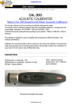
NITROUS OXIDE SENSOR USER MANUAL
Nitrous oxide sensor manual
Copyright © 2015 · Unisense A/S
Version July 2015
NITROUS OXIDE SENSOR MANUAL
UNISENSE A/S
TABLE OF CONTENTS
WARRANTY AND LIABILITY . . . . . . . . . . . . . . . . . . . . . . . . . . . . . . . . . . . . . . . . . . . . . . . . . . . 6
CONGRATULATIONS WITH YOUR NEW PRODUCT! . . . . . . . . . . . . . . . . . . . . . . . . . . . . 7
Support, ordering, and contact information
7
OVERVIEW . . . . . . . . . . . . . . . . . . . . . . . . . . . . . . . . . . . . . . . . . . . . . . . . . . . . . . . . . . . . . . . . . . . . 9
GETTING STARTED . . . . . . . . . . . . . . . . . . . . . . . . . . . . . . . . . . . . . . . . . . . . . . . . . . . . . . . . . . 10
Unpacking and connecting a new sensor
Pre-activation and Polarization
Pre-activation procedure
Polarization Calibration
Zero nitrous oxide reading
Nitrous oxide response reading
10
10
11
11
12
12
12
MEASUREMENTS . . . . . . . . . . . . . . . . . . . . . . . . . . . . . . . . . . . . . . . . . . . . . . . . . . . . . . . . . . . . 15
Mounting the sensors
Electrical noise
Interference
15
15
16
ADVANCED USE OF THE N2O SENSOR . . . . . . . . . . . . . . . . . . . . . . . . . . . . . . . . . . . . . . . . 17
STORAGE AND MAINTENANCE . . . . . . . . . . . . . . . . . . . . . . . . . . . . . . . . . . . . . . . . . . . . . . 18
Cleaning the sensor
18
REFERENCES . . . . . . . . . . . . . . . . . . . . . . . . . . . . . . . . . . . . . . . . . . . . . . . . . . . . . . . . . . . . . . . . . 19
TROUBLE SHOOTING . . . . . . . . . . . . . . . . . . . . . . . . . . . . . . . . . . . . . . . . . . . . . . . . . . . . . . . 20
APPENDIX: EQUILIBRIUM N2O CONCENTRATIONS . . . . . . . . . . . . . . . . . . . . . . . . . . 22
WARRANTY AND LIABILITY
Notice to Purchaser
This product is for research use only. Not for use in human diagnostic or
therapeutic procedures.
Warning
Microsensors have very pointed tips and must be handled with care to
avoid personal injury and only by trained personnel.
Unisense A/S recommends users to attend instruction courses to ensure
proper use of the products.
Warranty and Liability
The Nitrous Oxide sensor is covered by a 60 days limited warranty.
Microsensors are a consumable. Unisense will only replace dysfunctional
sensors if they have been tested according with the instructions in the
manual within 14 days of receipt of the sensor(s).
The warranty does not include repair or replacement necessitated by
accident, neglect, misuse, unauthorized repair, or modification of the
product. In no event will Unisense A/S be liable for any direct, indirect,
consequential or incidental damages, including lost profits, or for any
claim by any third party, arising out of the use, the results of use, or the
inability to use this product.
Unisense mechanical and electronic laboratory instruments must
only be used under normal laboratory conditions in a dry and clean
environment. Unisense assumes no liability for damages on laboratory
instruments due to unintended field use or exposure to dust, humidity
or corrosive environments.
Repair or Adjustment
Sensors and electrodes cannot be repaired. Equipment that is not
covered by the warranty will, if possible, be repaired by Unisense A/S
with appropriate charges paid by the customer. In case of return of
equipment please contact us for return authorization.
For further information please see the documents General Terms of Sale
and Delivery of Unisense A/S as well as the manuals for the respective
products.
6
CONGRATULATIONS WITH YOUR NEW PRODUCT!
Support, ordering, and contact information
The Unisense nitrous oxide microsensor is a miniaturized
Clark-type nitrous oxide sensor with a guard cathode designed for
research applications within environmental sciences.
If you wish to order additional products or if you encounter any
problems and need scientific/technical assistance, please do not
hesitate to contact our sales and support team. We will respond to
your inquiry within one working day.
E-mail: [email protected]
Unisense A/S
Tueager 1
DK-8200 Aarhus N, Denmark
Tel: +45 8944 9500
Fax: +45 8944 9549
Further documentation and support is available at our website
www.unisense.com.
REPLACEMENT OF SENSORS
Unisense will replace sensors that have been damaged during shipment provided that:
•
The sensors were tested immediately upon receipt in accordance with the delivery note
and the manual
•
The seal is still intact.
•
The sensors are returned to Unisense for inspection within two weeks.
•
The sensors are correctly packed for return to Unisense, in accordance with the note
included in the sensor box.
7
RECOMMENDED AMPLIFIERS
One-channel amplifier: Microsensor Monometer or Microsensor In Situ
Amplifier Box
Multi-channel amplifiers: Microsensor Multimeter
8
OVERVIEW
This manual covers all the Unisense N2O sensors.
With its minute tip size, excellent response time, and insignificant
stirring sensitivity the Unisense nitrous oxide sensor makes it
possible to make reliable and fast measurements with a high
spatial resolution.
WARNING
Unisense sensors
are neither
intended nor
approved for use
on humans
The Unisense nitrous oxide microsensor is a miniaturized
Clark-type sensor with an internal reference and a guard cathode.
In addition, the sensor is equipped with an oxygen front guard,
which prevents oxygen from interfering with the nitrous oxide
measurements. The sensor is connected to a high-sensitivity
picoammeter and the cathode is polarized against the internal
reference. Driven by the external partial pressure, nitrous oxide
from the environment will penetrate through the sensor tip
membrane and be reduced at the metal cathode surface. The
picoammeter converts the resulting reduction current to a signal.
The internal guard cathode is also polarized and scavenges oxygen
in the electrolyte, thus minimizing zero-current and polarization
time.
AVAILABLE N2O SENSORS
N2O25 (tip diameter 20-50 µm)
N2O100 (tip diameter 70-120 µm)
N2O-spec - customer specified
9
GETTING STARTED
Unpacking and connecting a new sensor
When receiving a new microsensor, first remove the
shock-absorbing grey plastic net. Then secure the sensor in a safe
position (e.g. micromanipulator or calibration chamber) before
connecting it to the measuring meter.
The signal from the nitrous oxide sensor is generated in
picoamperes. Therefore the nitrous oxide sensor must be
connected to a picoammeter amplifier unit during measurements.
WARNING
Do not remove the
seal and protective
plastic tube
before these steps
and calibration
are successfully
completed.
Pre-activation and Polarization
Please see procedure below.
Pre-activation: Nitrous oxide sensors have a metal cathode which
during normal exposure to oxygen over time will acquire an
oxidated surface layer. If the sensor is new or has not been used
recently, this layer must be “pre-activated” in order for the sensor
to work. This is done by applying a voltage of -1.3 V for a short
time prior to the period of polarization which is required for most
electrochemical sensors.
WARNING
Incorrect
polarization may
destroy the sensor.
Polarization: The electrolyte inside the sensor can contain large
amounts of oxygen which must always be removed before the
sensor is stable. This is done by the guard cathode inside the
sensor during the period of polarization (for some other sensor
types referred to as pre-polarization) and this process requires
some time, depending on the dimensions and exact proportions
of the individual sensor.
IMPORTANT:
If the sensor is new or not recently used, follow the procedure for PRE-ACTIVATION.
For recently used N2O sensors, follow the procedure for POLARIZATION.
Please read both sections before starting the relevant procedure.
10
For directions on adjusting the polarization on Microsensor
Multimeter/Monometer or the PA2000, please consult the relevant
manual.
Pre-activation procedure
1. Secure the nitrous oxide sensor with its
tip immersed in nitrous oxide free water.
(It does not harm the sensor to be in air
instead, but pre-activation, polarization,
and calibration might as well be made with
the same set-up).
2. Using a Microsensor Multimeter or
Monometer:
Connect the sensor to the amplifier. Turn
the polarization to -1.3V and leave for
approximately 30 minutes.
Using a PA2000 amplifier:
Connect ONLY the BNC connection of the
sensor and turn the polarization voltage to
-1.3 V.
On the computer screen or display you will
see a very high signal. Wait for five minutes.
Polarization
1. Using a Microsensor Multimeter:
Turn the polarization voltage to -0.8 V.
Using a PA2000 amplifier:
Turn the polarization voltage to -0.8 V.
Connect the yellow guard wire to the
yellow connection on the meter.
2. On the computer screen you will see a
sharp decrease followed by a rapid increase
in the signal. After this, the signal will
stabilize with an initial rapid and then a
11
more slow decrease. Wait until the signal
is below 20 mV and stable. This may take
many hours, e.g. 12 hours (see below). If
the sensor signal does not reach this value,
please go to the Troubleshooting section.
In general you should polarize for as long as possible before
calibration and measurements to get maximum stability. Unisense
recommends that you perform the pre-activation the day
before measurements and then leave the sensor to be polarized
overnight. If the signal does not stabilize or is too high or too low,
see ‘Trouble-shooting’.
Calibration
Calibration must be performed after the sensor signal has
stabilized. Nitrous oxide sensors respond linearly in the range of 0
to 2.5% nitrous oxide and signals can thus be linearly converted to
partial pressure.
Check and repeat calibration at appropriate intervals. Shortly after
taking a sensor into use, the appropriate interval may be 2 hours;
when the sensor has been used for some time, it may be 24 hours.
To minimize the need for calibrations, keep the sensor polarized
between measurements, unless the time between measurements
exceeds several days.
The membrane permeability of nitrous oxide microsensors
changes with time, so a change in signal of up to 50% may occur
over months.
Zero nitrous oxide reading
Place/keep the sensor tip in nitrous oxide free water and read the
signal. This signal is your calibration value for zero nitrous oxide
conditions.
Nitrous oxide response reading
The nitrous oxide sensor, in the standard version, responds
linearly between 0-500 µM N2O (0-2.5% N2O. This does not
apply for high range sensor versions. Therefore a two-point
12
IMPORTANT
Calibration must
be performed after
pre-polarization
when the sensor
signal has
stabilized.
CALIBRATION
As N2O microsensors respond
linearly to changes
in N2O concentrations, a two-point
calibration is
sufficient.
calibration is sufficient. Prepare water with a defined nitrous
oxide concentration (partial pressure), which is slightly above the
maximum expected nitrous oxide concentration (partial pressure)
in the samples. Never expose the sensor to concentrations more
than the specified linear range - it may cause irreversible damage
to the sensor.
A defined nitrous oxide concentration can be obtained by two
different procedures:
b) Add a defined volume of nitrous
oxide saturated water to a defined
volume of water in a calibration
chamber. For instance adding 3,679
ml of nitrous oxide saturated to 996,32
ml water gives a concentration of 100
µM at 20°C (see Table 1), as 3,679 ml of
nitrous oxide saturated water contains
WARNING
Bubbling of water
with any gas may
cause the water to
cool considerably.
Monitor the
temperature to find
a suitable bubbling
rate, which does
not cool the water
significantly.
Calibration chamber CAL300
a) Use a gas mixture controller to obtain a defined mixture of
nitrous oxide and nitrous oxide-free inert bulk carrier gas from
a gas tank (e.g. N2) . For instance, to obtain a nitrous oxide
concentration of 100 µM in the calibration chamber at 20°C,
bubble the water in the calibration chamber with a gas mixture
containing 1 atm. N2 and 0,003679 atm. N2O (nitrous oxide partial
pressure 0.003679 atm. * solubility 27,05*10-3 mol/liter/atm. =
100 µmol/liter, see Table 1). For a Unisense 300 ml calibration
chamber CAL300, 5 minutes of bubbling at a rate of 5 L per
minute is sufficient time to achieve 99% of the concentration.
If the equipment (gas mixture controller) is available, this
method can be convenient, because it is possible to switch
between different nitrous oxide conditions without changing
the water. Use the solubility table (Table 1) to find the correct
mixture at temperatures other than 20°C. For obtaining correct
concentrations it is important that the headspace above the
water in the calibration chamber is closed except for one hole,
which should be only slightly larger than the microsensor shaft.
This effectively prevents ambient air from entering the vessel.
We recommend the Unisense Calibration chamber, CAL300, and
rubber stoppers for calibrations.
WARNING
Never expose the
sensor to concentrations more than
500 micromolar
N2O - it may
cause irreversible
damage to the
sensor*
* Do not apply for high range sensor versions.
13
100 µmol nitrous oxide. Using a calibration chamber containing
200 ml, reduce the volume of added nitrous oxide saturated water
by a factor of 5 for obtaining 100 µM, and so on. After adding
nitrous oxide-saturated water to the calibration chamber, mix it
thoroughly for a few seconds and read the signal when it is stable.
Do not stir bubbles into the water and do not mix by bubbling, as
this will flush nitrous oxide from the water. A magnetic stirrer is
also not recommended as a mixing tool because it can introduce
electrical noise to the signal. The nitrous oxide in the water will
slowly escape to the atmosphere and the concentration can only
be considered constant for a few minutes.
If the sensor functions according to the above description,
carefully remove the seal and the protective tube before
making measurements.
14
MEASUREMENTS
Nitrous oxide sensors can be used for a wide variety of
measurements (please see our web page www.unisense.com for
further information). They are most commonly used for making
profiles in e.g. sediments or tissues where a high spatial resolution
is required or for nitrous oxide measurements in water samples.
Mounting the sensors
Although the Unisense microsensors are made of glass, the tip
is flexible and can adjust slightly around physical obstacles. The
sensor is thus rather sturdy in the longitudinal direction. However,
large obstacles like stones or lateral movements of the sensor
when the tip is in contact with a solid substrate may cause the tip
to break.
TEMPERATURE
Closely monitor
the temperature.
The temperature
coefficient varies
from sensor to
sensor but is
approximately
2-3% per oC.
Furthermore, due to the small size of the microsensor tip
and to the steepness of gradients in many environments, a
displacement of the sensor tip of only a few microns may change
its environment.
Therefore, we recommend that measurements be performed
only in a stabilized set-up free of moving or vibrating devices.
We recommend the Unisense laboratory stand LS18 and the
Unisense micromanipulator MM33 (double MM33-2) for laboratory
use. For in situ use we recommend our in situ stand (IS19) and a
micromanipulator.
Electrical noise
The signal of the microsensor is very small (10-13 to 10-10 ampere).
Although both the Unisense picoammeter and the Unisense
nitrous oxide microsensors are quite resistant to electrical
noise from the environment, electrical fields may interfere with
the sensor signal. Therefore we recommend that unnecessary
electrical/mechanical equipment is switched off and the sensor or
wires are not touched during measurements and signal recording.
15
Interference
Exposure to high concentrations of sulfide should be avoided as it
can affect the sensitivity of the nitrous oxide microsensor.
Nitric Oxide (NO) is interfering the N2O sensor signal.
On suspicion of sensor damage, repeat calibration and consult
‘Trouble-shooting’.
16
ADVANCED USE OF THE N2O SENSOR
Unisense can construct nitrous oxide sensors for customer
requested applications at an additional cost. Unisense provides
several options for customizations (e.g. tip size, response time,
pressure tolerance, and stirring sensitivity) and adaptations
(e.g. mounting in needle or flow-through cell), making accurate
measurements possible for even more applications.
Please visit our website for more information.
17
STORAGE AND MAINTENANCE
Always store the sensor in the protective plastic tube used for
shipping. The nitrous oxide microsensor can be stored with the
tip exposed to water or air. The room in which the microsensor
is stored should be dry and not too hot (10-30°C). If the sensor is
used regularly it can be stored polarized.
Cleaning the sensor
Depending on which substance is present on the sensor tip or
membrane, the sensor can be cleaned with different solutes.
The standard method is to rinse with 96% ethanol, then rinse with
0.01 M HCl and rinse with water. This will remove most substances.
Alternatively it is possible to rinse with 0.1M NaOH, isopropanol, or
other detergent
18
REFERENCES
• Andersen, K., T. Kjaer, and N. P. Revsbech.
2001. An oxygen insensitive microsensor
for nitrous oxide. Sensors and Actuators
B-Chemical. 81(1):42-48.
• Elberling, B., Christiansen, H.H. and Hansen,
B.U. 2010. High nitrous oxide production
from thawing permafrost. Nature geoscience
3:332-335. Abstract
• Horn, M., A. Schramm, and H.L. Drake. 2003.
The earthworm gut: an ideal habitat for
ingested N2O-producing microorganisms.
Appl. Environ. Microbiol. 69, 1662-1669.
• Revsbech, N. P., and B. B. Jørgensen. 1986.
Microelectrodes: Their Use in Microbial
Ecology, p. 293-352. In K. C. Marshall (ed.),
Advances in Microbial Ecology, vol. 9.
Plenum, New York.
19
TROUBLE SHOOTING
Problem
Possible cause
Insoluble compounds deposited at the sensor tip
Solution
Rinse with 96% ethanol, rinse with 0.01M HCl and rinse with water
Problem
An unstable signal or the signal fluctates if the setup is touched or
equipmen is introduced in the medium you are measuring in
Electrical disturbance of the sensor through the tip membrane
Possible cause
Solution
Ground the set-up using the blue grounding cable supplied with
the picoammeter. Connect the reference plug on the picoammeter (blue plug) with the medium you are measuring in.
Problem
High and drifting signal
Possible cause
The sensor tip is broken
Solution
Replace the microsensor
Problem
A high signal
Possible cause
Solution
Possible oxygen interference if the oxygen front guard is
damaged
Replace the microsensor
Problem
A high signal (2)
Possible cause
Solution
20
A slow response
Air is trapped in the tip
Degas water by boiling and subsequent cooling or by 10 min
of vacuum treatment. Immerse the sensor tip for 20 min in the
degassed water. Repeated or prolonged treatment may be
necessary.
Problem
Possible cause
Solution
The signal is very low
Contamination of the cathode surface (e.g. by sulfide) or loss of
the cathode material due to excessive vibration.
Replace the microsensor.
If you encounter other problems and need scientific/technical assistance, please contact
[email protected] for online support (we will answer you within one workday)
21
APPENDIX: EQUILIBRIUM N2O CONCENTRATIONS
Equilibrium nitrous oxide concentrations (mmol/liter) at ambient
partial pressure of 1 atm. in water as a function of temperature and
salinity.
(‰) / oC
0
5
10
16
22
26
30
36
40
0
59.35
48.46
40.16
32.66
27.05
24.09
21.61
18.61
16.98
10
55.85
45.73
37.99
30.96
25.69
22.91
20.57
17.73
16.18
20
52.58
43.15
35.93
29.35
24.40
21.78
19.58
16.89
15.42
30
49.50
40.73
33.98
27.82
23.18
20.71
18.63
16.09
14.70
35
48.03
39.56
33.05
27.09
22.59
20.19
18.18
15.70
14.35
38
47.17
38.88
32.50
26.66
22.24
19.89
17.91
15.48
14.15
40
46.60
38.43
32.14
26.37
22.01
19.69
17.73
15.33
14.01
Source: Weiss, R.F; Price, B. A.: Marine, Chemistry, 1980, 8, 347-359
22
UNISENSE, DENMARK
www.unisense.com · [email protected]