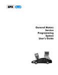
1
May 2001
Volume 3, No. 5
Techline News
OnStar Service Issues
SI 2000 Now Updated Weekly
Beginning the first week in April,
the SI 2000 website is being updated
once a week. The latest information
will be available each Friday morning.
This is twice as often as before.
To access the information, use
your internet browser to go to website http://service.gm.com. Do not
use “www” in this address.
Click on Service Manuals,
Bulletins and Campaigns. You will
need to type your User Name and
Password to go past this point.
Next, on the SI 2000 Home Page,
select the area you’re interested in.
By the way, notice that you now
have a choice of two languages:
English and French.
The information that is updated
each week includes Service Manual,
Bulletins, Campaigns, and Preliminary
Information (PI) titles.
By clicking on Latest News, you
will see a list of Bulletins, Campaigns
and PI titles that have been recently
added. A box at the end of the page
allows you to select 2, 4, 6 or 8
weeks. Service manual revisions and
additions are not indexed.
The internet will always be your
freshest source of service information. The service information on GM
ACCESS will continue to be updated
on a two week cycle. And it’s even
possible that new bulletins may
appear on SI 2000 before the paper
copies arrive in your dealership.
– Thanks to Lisa Scott
Most systems on GM vehicles are
integrated completely into the vehicle.
They carry out their intended functions
without reacting to influences from outside the vehicle.
A few systems, though, can be
affected by the behavior of something
outside the vehicle. For instance, the
radio depends on receiving an acceptable
signal from the radio station’s tower.
Radio reception can be affected by external interference from overhead electrical
wires, faulty ignition in nearby vehicles,
and driving past tall buildings or through
tunnels.
Similarly, the proper operation of the
OnStar system is affected both by invehicle components and by influences
coming from outside the vehicle. The
OnStar system has several independent
elements that must work together in
order for the system to function properly.
The hardware in the vehicle . The
Vehicle Interface Unit and Vehicle
Communications Unit, the cellular anten na, the GPS antenna, and related cables
must operate properly and must interface
continued on page 2
1
Contents
OnStar Service Issues . . . . . . . . . . . . . . . . . . . .1
SI 2000 Now Updated Weekly . . . . . . . . . . . . . .1
Dealership PC Network Strategies . . . . . . . . . . .4
Dinghy Towing -- A Reminder . . . . . . . . . . . . . . .5
Recognizing OE Batteries . . . . . . . . . . . . . . . . .5
New Mid-Size Truck Rear Suspension System . . . .6
Malibu Exhaust Rattle . . . . . . . . . . . . . . . . . . . .7
Armrest Lowers Itself During Braking . . . . . . . . .7
GM Service Clubs, Part 4 . . . . . . . . . . . . . . . . .7
TAC Tips . . . . . . . . . . . . . . . . . . . . . . . . . . . . .8
Bulletins . . . . . . . . . . . . . . . . . . . . . . . . . . . . .8
Service Operations
correctly with the vehicle.
GM TechLink is a monthly magazine
for all GM retail technicians and service consultants providing timely
information to help increase knowledge about GM products and improve
the performance of the service
department. This magazine is a companion to the GM Edge publication.
Publisher & Editor:
Mark Stesney
GM Service Operations
[email protected]
Technical Editor:
Jim Horner
[email protected]
1-248-816-3641
Marie Meredith
Desktop Publishing:
Greg Szpaichler, MediaWurks
[email protected]
1-248-649-5465
Write to:
TechLink
PO Box 500
Troy, MI 48007-0500
GM TechLink on the Web:
http://service.gm.com
General Motors service tips ar e
intended for use by professional technicians, not a "do-it-yourselfer." They
are written to inform those technicians of conditions that may occur on
some vehicles, or to provide information that could assist in the proper
service of a vehicle. Properly trained
technicians have the equipment, tools,
safety instructions and know-how to
do a job properly and safely. If a condition is described, do not assume
that the bulletin applies to your vehicle or that your vehicle will have that
condition. See a General Motors dealer servicing your brand of General
Motors vehicle for information on
whether your vehicle may benefit from
the information.
Inclusion in this publication is not necessarily an endorsement of the individual or the company.
Copyright© 2001 General Motors Corporation
All rights reserved.
The OnStar Call Center
Application. This application must be
able to send and receive information
from the vehicle.
Signals from US GPS satellites. The
OnStar equipment in the vehicle must
also be able to receive and interpret signals from the US Global Positioning
Satellites orbiting above the earth.
The Cellular Phone System
Issues
There are numerous issues that arise
from utilizing a cellular system supplied
by an independent third party. Cellular
towers can be busy, depending on the
level of traffic on the system. Some
areas of the country may have a limited
or inadequate number of cellular towers
to handle the load of cellular phone calls.
The OnStar system relies upon all of
these independent systems to work
together to provide service to OnStar
subscribers. It is precisely this interaction
that makes the OnStar system unique.
But this interaction of internal and
external factors can complicate the proper diagnosis of customer concerns.
Production Manager:
FAX number:
The cellular phone network. The
cellular network must be able to deliver a
two-way cellular call.
The diagnosis of the in-vehicle hardware is not significantly different from
diagnosing other on-vehicle modules. The
real difficulty in diagnosing the OnStar
system lies in assessing whether the
customer’s concern is the result of a
problem in the vehicle hardware or an
issue with the other external systems
necessary for OnStar operation.
On-Vehicle Equipment Issues
Many on-vehicle equipment issues
can be resolved by simply ensuring that
the system components are installed or
connected properly. The cellular antenna
mast must be installed on the vehicle
and the coax cable must be tightly connected to the Vehicle Communication
Unit (VCU) and the antenna base.
Vehicle Communication Unit (VCU)
and the Vehicle Interface Unit (VIU)
The GPS antenna must have a good
connection both at the antenna and at
the Vehicle Interface Unit (VIU). The GPS
antenna coax is rather fragile cable.
When inspecting or replacing the cable,
do not bend it to a curve less than 2 inches in diameter or the cable will be damaged.
Cellular Phone System
OnStar has made an arrangement
with Verizon to provide cellular service
for the OnStar system. To provide OnStar
with truly national coverage, Verizon has
signed agreements with local carriers in
areas where Verizon doesn’t have a
license.
In order for a cellular call to be delivered between OnStar and a vehicle,
Verizon must ensure that every local carrier in the chain handling the call must
recognize the phone number assigned to
each vehicle.
Long distance is yet another aspect.
At present, OnStar has two call centers,
one in Charlotte, NC and one in Troy, MI.
Unless a vehicle is located in one of
these two cities, it is likely that the vehicle will at some point have to make a
long distance call. This involves a long
distance carrier and adds to the complexity.
While this sounds very complicated, it
is usually seamless. The vast majority of
OnStar calls are successful. The ones
that may require service are typically the
exceptions, not the norm.
GPS System Issues
The Global Positioning System (GPS)
is an example an everyday civilian benefit
resulting from a system originally devel-
2
Return to page 1
Other New Refinements
oped for the military.
There is a mathematical principle
called triangulation that says you can pinpoint an unknown location if you know its
distance from three known locations.
GPS uses 24 NAVSTAR satellites orbiting
the earth. The location of each satellite is
known at any given time. The satellites
constantly broadcast radio signals. A GPS
receiver compares the amount of time it
takes for the signals from at least three
different satellites to reach the receiver.
By translating time into distance, it can
calculate the receiver’s location on earth.
The OnStar receiver in the vehicle
receives the GPS data, decodes it, and
transmits the vehicle’s location by cell
phone to the OnStar call center.
the voice recognition software incorporat ed in the vehicle hardware. If there’s a
problem with this part of the system, it’s
right there in the vehicle. Then, there’s
the voice recognition software at the
other end of the call within the Virtual
Advisor System. This part of the system
can be affected by interferences on the
cellular communication network.
Most voices are readily recognized,
but some users may experience difficulty
with certain numbers, words, or phrases.
The customer may have to be trained
to modify their speech pattern slightly to
take full advantage of the voice recognition system. There are some tips for
using voice recognition on the MyOnStar
website, in SI 2000, and in the OnStar
owners manual.
If the system can recognize at least
one word, the hardware is functioning
properly. Do not replace it.
The system may have difficulty recognizing commands when multiple people
are talking or there’s excessive road
noise.
SI 2000 has a voice recognition diagnostic along with some tips for proper
intonation and other adjustments.
Follow this path:
GPS System
- Body and Accessories
- Cellular Communication
GPS technology may be affected by
external factors. Many of these are similar to the things that affect conventional
radio or TV reception.
- There must be a direct line of sight
between the receiver antenna and
the satellites.
- Signals may be obstructed by terrain
or buildings, preventing reception by
the receiver.
- Multipath error, caused by signals
being reflected from objects befor e
reaching the antenna, affects the
system’s accuracy.
Voice Recognition Issues
The majority of 2001 vehicles are
capable of offering two services called
OnStar Personal Calling and OnStar
Virtual Advisor. These services use a
voice recognition system.
There are two distinct voice recognition systems at work here. First, there’s
- Description and Operation
- OnStar Description and Operation
- General Tips for Better Speech
Recognition
and
- Personal Calling Commands
Some of the conditions explained by
SI 2000 include noise from open windows or sunroof, speaking too soon after
a prompt, a high pitched voice, and
emphasis on certain sounds.
New Product Features
Several of the new 2002 vehicles,
starting with the 2002 S/T utilities
(Bravada, Envoy and TrailBlazer), have the
latest iteration of OnStar hardware, designated as F1. The predominant feature is
that it combines the VIU and the VCU
into one package, called the Vehicle
Communications and Interface Module
(VCIM).
- Progression tones replace the tradi tional audio feedback of a ringing
phone, busy signal or other similar
message. The tone is an audio note
that repeats at regular 5 to 15 second intervals.
When the OnStar Call Button or the
emergency key is pressed, you will hear
“connecting to OnStar,” followed by the
progression tones. With normal cellular
connection times, the tones could last as
long as three minutes before a connection is made.
It is important to wait until the system makes a connection, or the “unable
to connect to OnStar” message is heard.
OnStar recommends that you try to connect several times. If a successful connection cannot be made, you will need to
contact the OnStar call center to request
verification that the OnStar system in the
vehicle is registered with the national cellular network.
In rare instances, it is possible that
the message “OnStar request ended”
could be heard. This indicates that the
cellular connection was interrupted
before completing a connection to
OnStar. In these instances wait for a
short period of time and attempt to connect again.
- The F1 module adds the capability of
setting a code for a disconnected
GPS antenna.
- While the VCIM combines the functionality of the VIU and the VCU into
one package, the system will still set
internal communication codes. This
would drive the replacement of the
unit.
- The replacement of the VCIM will
require the Station ID (STID) and
Electronic Serial Number (ESN) be
communicated to the call center.
Top OnStar Issues
Any time an OnStar VIU is replaced,
reconfiguration is necessary. Press the
blue button and tell the advisor you are a
technician who has just replaced a VIU
and you need to update the customer’s
account. You will need the STID number
from the replacement part when you call.
When replacing an OnStar VCU, you
will also need to contact the OnStar call
center to perform a reconfiguration. You
will need to have the module’s ESN avail able when you call.
Refer to the VIU or VCU replacement
procedure or the OnStar reconfiguration
procedure in SI 2000.
– Thanks to Dale Tripp, Mike Batchik,
Dean Tobias, and Dave Mitchel
3
Return to page 1
Dealership PC
Network
Strategies
gramming data) on a regular basis. In
shops with electronic repair orders, they
need nearly constant access to the RO
files, both to determine what work is
needed and to record services performed
and parts used.
The recommended guideline is one
PC per 2 or 3 technicians. Because each
service department is unique, this guideline should be a consideration when evaluating overall productivity.
The SI 2000 and TIS software are
flexible enough to run on relatively common business-grade systems.
Specifications are available from GM
Service Operations at website
http://service.gm.com/techlineinfo/.
Typical GM ACCESS Configuration
As the automobile enters its second
century, it’s pretty obvious that computers are playing an ever-increasing role,
both in the operation of the vehicle and in
the service department.
It’s no longer possible to get along
with just one PC in your service department. Service information comes into
your dealership from a number of
sources, using a variety of media. And
once the information is in the dealership,
it needs to be distributed and made
accessible to a number of users.
DEVELOPING A
DEALERSHIP STRATEGY
http://service.gm.com/techlineinfo/
multiplepc.html
Here are some highlights from this
document.
Technicians need ready access to SI
2000 (service information) and TIS (pro-
GM ACCESS
A satellite-based intranet providing two-way communication
between GM and the dealership.
Of the many aspects of dealership
operation communicated over GM
ACCESS, several are directed at
the service department.
- Incremental updates of SI 2000
- Updates of TIS 2000
TWO MAIN STRATEGIES
SI 2000
There are two main strategies for distributing information to the technicians’
individual PCs.
This is the electronic version of
the service manual, service and
campaign bulletins, and Product
Information titles. It is available on
the internet (weekly updates), and
can be downloaded from Techline
CDs or from GM ACCESS (biweekly updates).
- download all of the data from
Techline CDs to each individual PC
- download all of the Techline data to
a central server, with individual PCs net worked to the server
In the second scenario, the network,
it’s also possible to connect the server to
an internet service provider, which then
links each individual PC to the internet.
To further expand the network concept, it may be possible to use your
Dealer Service Provider (DSP) hardwar e
to access SI 2000 data, either by individual downloads or through a network. This
means that each PC can do multiple duty.
The question, then, is how to develop
a logical strategy that works for your specific dealership. A well-thought out strategy helps determine what hardware is
needed, as well as how to interconnect it
for maximum flexibility and convenience.
With good planning, it is be possible to
improve the efficiency of your GM
ACCESS and PC network without having
to add a lot of new equipment. A qualified system administrator should review
and refine the strategy before anything is
purchased or installed.
At the recent 2001 National Auto
Dealer Association (NADA) convention,
GM Service Operations made
Networking Strategy the theme. GMSO
talked to many dealers, and focused on
how to provide the service department
with enhanced alternatives to the standard GM ACCESS network. This information is available on the internet at the following address:
HOW SERVICE
INFORMATION GETS TO
YOUR DEALERSHIP
The http://service.gm.com
website is the internet portal to SI
2000, as well as numerous other
service related resources, including this TechLink magazine.
TIS 2000
The Techline Information
Systems 2000 consists of service
programming software needed to
update vehicle programming, using
the Tech 2. Bi-weekly updates of
TIS can be downloaded from GM
ACCESS and from the GMSO
website.
the update CDs to arrive.
- In dealerships where SI 2000 is on a
central server, the system administrator
can download updates weekly from the
internet. Again, there’s no need to wait
for updates on CD or from GM ACCESS.
GM ACCESS with Internet and
DSP Connections
WHAT’S BEST?
There is no single fits-all answer. But
there are some points to consider.
- Dealerships are encouraged to provide technicians with a high-speed
access to SI 2000 directly from the internet. A major benefit is that the data is
updated automatically, every week.
There’s no need to manually download
updates from GM ACCESS or wait for
- The direct-to-internet system is ideal
for service departments that are not connected to GM ACCESS at all. Cases like
these are usually where the service or
body shop is in a remote location or
building, away from the GM ACCESS
system.
- GMSO does not recommend a
modem dialup connection to the internet,
because this is the lowest level of performance. Some of the configurations that
provide a continuous Broadband connec tion are ISDN, DSL and T-1 lines.
Availability and cost vary with location.
– Thanks to Mike Waszczenko
4
Return to page 1
Towing News
Dinghy Towing -A Reminder
removed. For these trucks, the preferred
towing method requires use of a platform
trailer which lifts all four wheels from the
pavement.
The latest information on dinghy towing
is found in Bulletin 00-00-89-008A, dated
April, 2001. Dinghy towing refers to towing
a vehicle with all four wheels on the
ground, for instance behind a motor home.
IMPORTANT: Refer to the service man ual for propeller shaft removal and installation. Provisions must be made to keep the
lubricant in the transmission and dirt out.
After towing, verify that the transmission
fluid is at the proper level before driving the
truck.
Your customers may have questions
about which vehicles can be towed this
way, and how to do it correctly. Refer them
to the Owner’s Manual for guidance.
Details are also included in the bulletin
mentioned above. Be sure to read the bulletin completely and follow the procedures
exactly, to avoid damage to the vehicle
being towed. These are the highlights.
Passenger Cars
IMPORTANT:: Cars must not be towed
backward or the transmission may be damaged.
The bulletin spells out exactly which
vehicles may be towed. Generally, they are
those with front wheel drive and either the
automatic transaxle 4T40-E or 4T45-E, or
the 5-speed manual transaxle MK7, MJ1,
M86, or M94.
IMPORTANT:: Manual Transmissions
M58, M42, and MM5 should not be towed
with all four wheels on the ground.
- First, set the parking brake.
- Because the ignition key must be
turned from the LOCK position, it’s
necessary to pull the fuse(s) indicated
in the Owner’s Manual. This prevents
the instrument panel or electronic
PRNDL from draining the battery.
- After hooking the vehicle to the towing
vehicle, the steering column must be
unlocked. The Owner’s Manual specifies the appropriate ignition key position to ensure that the steering is
unlocked to allow the front wheels to
follow the tow vehicle, and to ensure
that the transmission shifter is
unlocked, without starting the engine.
- Shift the transmission to Neutral. Then
release the parking brake.
- Do not exceed 65 mph while dinghytowing.
Mid/Full Size Trucks with
4-Wheel or All-Wheel Drive
Certain T and K trucks may be dinghytowed with the transfer case shifted to
Neutral. These are listed in the Bulletin.
The remaining T and K trucks with 4wheel- or all-wheel-drive can be dinghytowed only with the propeller shafts
propeller shaft must be removed and the
steering column unlocked.
IMPORTANT: Refer to the service manual for propeller shaft removal and installation. Provisions must be made to keep the
lubricant in the transmission and dirt out.
After towing, verify that the transmission
fluid is at the proper level before driving the
truck.
- Thanks to Mike Ondre
For those vehicles that can be
dinghy-towed, follow this procedure.
- Set the parking brake.
- Place the automatic transmission in
PARK, or the manual transmission in
first gear.
- After hooking the vehicle to the towing
vehicle, shift the transfer case to
Neutral. Be aware that the vehicle can
roll, even if the transmission is in Park
or in gear.
- Release the parking brake.
- The steering column must be
unlocked. The Owner’s Manual specifies the appropriate ignition key position to ensure that the steering is
unlocked to allow the front wheels to
follow the tow vehicle.
Mid/Full Size Trucks with
Rear Wheel Drive
Recognizing Original
Equipment Batteries
If you have the need to distinguish
between an original equipment (OE)
AC Delco battery and an
aftermarket/service AC Delco battery,
here’s how.
The OE AC Delco battery has only
one label on top, and it is predominantly black and silver.
The aftermarket/service AC Delco
battery has two labels, and they are
predominantly blue and white.
Also the aftermarket/service AC
Delco battery is generally referred to as
a Professional series battery, while the
OE AC Delco battery is not. There may
be some non-Delphi manufactured batteries in the AC Delco aftermarket/service line which are not referred to as
Professional.
These vehicles should not be dinghytowed. The preferred towing method
requires use of a platform trailer which lifts
all four wheels from the pavement. If towing on all four wheels is unavoidable, the
Summary
Vehicle
Tow
Metro/Prizm
No
Cavalier/Sunfire/Malibu/
Alero/GrandAM
Yes
All other cars, auto. trans.
No
Tracker
Refer to
owner’s
manual
for
details
Corvette, Camaro, Firebird
No
4 Wheel Drives (T/Case)
Yes, If
T/Case
has
netural
Rear Wheel Drive
No
AC Delco Original Equipment Battery
Label
AC Delco Aftermarket/Service
Battery Labels
5
Return to page 1
New Mid-Size Truck
Rear Suspension
System
“It rides like it was on air.” Proud
owners have applied that fanciful claim
to lots of cars and trucks over the
years, but rarely can you take it literally.
Now you can. A new, sophisticated
electronically controlled air suspension
(ECAS) is either standard or available
coil springs. Otherwise, the 5-link suspension is the same.
The ECAS system consists of three
main groups of components:
- an air compressor and module
- air suspension sensors
- air springs
The air springs operate at a pressure of 45 - 103 psi, with a maximum
adding, subtracting, or maintaining air
in each of the inflatable springs. A sensor on each upper control arm determines when a change is needed. The
air compressor assembly, located on
the right rear chassis rail, handles the
task of moving air into or out of the air
springs as needed.
Incidentally, the compressor also
serves as an accessory inflator, similar
to other GM products. Simply attach a
hose to the air fitting and press the
control button located in the right rear
trim panel.
Compressor Operation
The compressor can inflate or
exhaust the air springs with the ignition
key in the ON position. The accessory
inflator feature can be turned on by
depressing the inflator button, with the
ignition on or off.
Upper and lower control arms
on the new 2002 Oldsmobile Bravada
and GMC Envoy sport utility models.
5-Link Rear Suspension
Before we get to the specifics of
ECAS, we need to take a short look at
the all-new 5-link rear suspension that
backs it up. This suspension system is
designed to enhance load-carrying
capability while providing a comfortable
ride.
In the base configuration, rear coil
springs are used for the first time in
these vehicles. The elimination of leaf
springs permitted the engineers to
divide the rear suspension’s two tasks
between two sets of components. The
coil springs take on only the ride and
load carrying functions. Location of the
rear axle is now assigned to five separate links, or control arms.
static pressure of 175 psi. The top and
bottom pistons are made of nylon, and
the air bellows are made of rubber. The
air springs operate over a temperature
range of -32°C to 80°C (-26°F to
176°F); short term exposure, 2 hours
or less -40°C to 90°C (-40°F to 194°F).
The expected service life is 10 years or
150,000 miles.
Regardless of the load being carried, the inflatable ECAS air springs
provide several benefits that coil
springs cannot:
- keeping the vehicle visually level
- providing optimal headlamp aiming
- maintaining optimal ride height
- provide optimum ride comfort at
different loading conditions
- provide good noise isolation
These tasks require the air springs
to adjust their height automatically;
each side is managed independently by
the ECAS module. This is done by
On each side, the axle’s up and
down movement is controlled by a pair
of longitudinal upper and lower control
arms, while side-to-side control is provided by a tie rod running behind and
parallel to the axle. And, of course,
conventional shock absorbers are used
at each side.
The duty cycle allows the compressor to run only a certain amount of
time. The compressor will not inflate or
exhaust during the time-out mode.
System operating pressure is
between 20 to 105 psi. The leakage
specification of the complete system
(compressor and air springs) allows a
vehicle-drop of less than 1.5 mm/24
hour.
Service Procedures Unique
to ECAS
SI 2000 contains comprehensive
service procedures for the ECAS system. Follow this path:
- Identify the 2002 vehicle
- Suspension
- Air Suspension
You will then have a choice of
Operation, Diagnostics, Repair,
Specifications, Schematics and
Component Locator sections.
Diagnosis
IMPORTANT: Because this system
does not communicate on the serial
data (Class 2) bus, your Tech 2 cannot
be used to diagnose it.
The system uses a flashing LED in
the inflator switch located in the right
rear trim panel to communicate system
faults. With the ignition on and the
engine off, the LED will flash stored
codes related to the various system
conditions. The codes flash similarly to
Electronically Controlled Air
Suspension (ECAS)
In the ECAS system, air springs
take the place of the standard metal
The compressor can exhaust up to
30 minutes after the key is turned off.
Height sensor
6
Return to page 1
the old Check Engine light diagnostic
codes. Flashing pulses repeat at the
rate of 0.5 seconds, with a 3-second
delay between codes.
Malibu Exhaust Rattle
After observing the codes, simply
perform the procedures associated
with each of the three Diagnostic
Codes.
the cavity in place. Obtain a piece of high
density closed cell foam, such as 3M
06370 Scotch Foam Black Vinyl or equivalent. The tape should measure 1 inch wide
x 8 inches long x 1/4 inch thick. Taper the
last inch of the foam tape to half its thickness to prevent a transition line from
showing on the outside of the armrest.
DTC 001 is associated with internal
component failures.
DTC 002 indicates right height sensor faults.
And DTC 003 indicates left height
sensor faults.
Diagnostic codes are cleared automatically when the ignition switch has
been cycled from off to on, and the
cause for setting the code has been
corrected.
Depressurization
Some repair procedures require
depressurizing the air suspension system before proceeding. This is spelled
out in detail in SI 2000. Here are some
highlights.
Depressurize the system with the
axle fully supported and set between
D-height and full jounce. Failure to follow these steps may cause damage to
the air springs.
Remove the air suspension fuse
before working on the rear suspension
to avoid affecting the calibration of the
leveling sensor.
The compressor bolts must be
removed and the compressor supported before the air supply line fittings
can be loosened to bleed pressure
from the springs.
– Thanks to Dave Smith, Jeff Downing,
and Eric Kenar.
GM Service Clubs,
Part 4
This is the fourth and final article in
a series.
GM service clubs around the country meet to talk about the service
issues that dealership service departments face each day.
This interactive communication is
one of the benefits for service managers who attend a local service club
meeting. The clubs provide a way for
service managers to access a wide
array of information from other dealership service departments as well as a
Some owners of 2001 Chevrolet
Malibus may comment on a rattle from
under the car. This may be caused by
insufficient clearance between the
exhaust pipe and the screw that secures
the fuel tank heat shield at the front.
There should be a minumum of 15 mm
clearance between the exhaust pipe and
the head of the screw. If the clearance
is less than 15 mm, place a suitable tool
on the head of the screw and push
upward until there is at least 15 mm of
clearance between the exhaust pipe and
the screw head.
Tapering the foam tape
Install the foam tape between the hard
ABS plastic cavity top edge and the foam
padding in the armrest, with the tapered
end toward the rear. Make sure you keep
the foam tape near the top surface of the
armrest. Restaple the material to the inside
edge of the hard ABS plastic surface. Make
– Thanks to Dave Dickey
Armrest Lowers Itself
During Braking
Owners of some 2000-2001 Pontiac
Grand Prix may comment that the rear
armrest lowers itself during braking, on
vehicles equipped with leather seats.
This condition is corrected by shimming
the outboard sides of the armrest.
Place the armrest in the down position.
Remove the cupholders by pushing rearward on the front of each side of the
cupholder and lifting up to disengage the
retainers.
Remove the staples located along the
outboard sides of the cupholder cavity,
leaving the staples at the front and rear of
number of GM sources.
Here is a list of additional GM service clubs. GM supports local service
clubs and many GM representatives
attend the club meetings. For more
information about GM service clubs,
contact any of the clubs listed below.
Earlier lists appeared in November
and December, 2000, and February
2001.
Foam tape installed
sure to use the same length staples as
were removed.
Complete this process on both sides of
the armrest, then reinstall the cupholder in
the armrest. Always road test the vehicle
to be sure you have corrected the condition. Usually one layer on each side corrects the condition, but if the armrest still
comes down, you may have to add a second layer of foam.
– Thanks to Fred Tebbets
West Central Service Managers Club
Contact: Les Guderian
Humboldt Motor Sales, Humboldt, IA
515.332.2764
WESTERN REGION
Los Angeles / Orange County Retail
Service Managers Club (LOSOR)
Contact: Mike Bowers
Peninsula Pontiac GMC Buick, Torrance, CA
310.257.4200
NORTH CENTRAL REGION
Fox Valley GM Service Managers
Association
Contact: Ben Gawaresky
West Side Garage, Berlin, WI
800.223.3302
North Bay Service Managers Club
Contact: Roger Cunningham
McConnell Chevrolet, Healdsburg, CA
707.433.3384
7
Return to page 1
GENERAL INFORMATION:
01-06-02-002; Whining Noise In
Passenger Compartment When Engine
RPM is 1700-2300 (Remove Coolant
Flow Restrictor); 2001 Chevrolet and
GMC C/K Models (Silverado, Sierra) with
8.1L Engine (VIN G -- RPO L18)
01-07-30-007; Release of New Torque
Converter Bolt; 2001 Cadillac Escalade,
1998-2001 Chevrolet Camaro, Pontiac
Firebird, 1999-2001 Chevrolet and GMC
C/K (New Style) Pickup and Utility
Models
99-00-89-011A; replaces 99-00-89011; New Key Code Information for 10Cut Keys; All 2000-2001 Passenger Cars
and Trucks Except Cadillac Catera,
Eldorado, Chevrolet Camaro, Lumina,
Metro, Prizm, Tracker, Pontiac Firebird,
Medium Duty Trucks
01-06-03-003; Generator Upper
Mounting Bolt Breakage (Replace Bolt
and Install Brace Rod Assembly); 19962000 Chevrolet and GMC C6-7
Conventional Medium Duty Models with
Gas Engine (VINs B, D, M, P -- RPOs
L21, LP4, LR0, LS0)
01-07-30-010; Torque Converter
Replacement; All 2001 and Prior GM
Passenger Cars and Trucks with ALL
Automatic Transmissions and Transaxles
00-00-89-015A; Warranty
Administration -- Repair Order (RO)
Documentation; 2001 and Prior
Passenger Cars and Trucks
01-06-04-010; Product Enhancements
to Improve Slow/No Start Conditions In
Extreme Cold Weather; 1999-2000
Chevrolet Tracker
01-00-89-006; February, 2001 Bulletin
Summary; 2002 and Prior Passenger Cars
and Trucks
01-06-04-011; Water in AIR Pump
and/or DTC P0410, P0412, P0415,
P0416, P0100, P0101, P0102 or DTC 48
(AIR System Disable Procedure); 19951996 Buick Roadmaster, Cadillac
Fleetwood, Chevrolet Caprice, Impala SS
with 4.3L or 5.7L Engine (VINs W, P -RPOs L99, LT1)
This review of service bulletins
released through mid-April lists the bulletin number, superseded bulletin number
(if applicable), subject and models.
HVAC:
01-01-38-005; Insufficient Heat From
Rear Heater During Extreme Cold
Weather (Replace Rear Heater Tee
Couplings); 2000-2001 Chevrolet and
GMC C/K Utility Models (Suburban,
Tahoe, Yukon, Yukon XL) Built Prior to
October, 2000
01-05-23-003; Revised Tool
Requirements for Front and Rear Brake
Caliper Overhaul; 1997-2001 Vehicles per
list
STEERING:
01-02-35-001; Steering Wheel
Squeaks When Turning (Install Insulating
Material); 1999-2001 Chevrolet Camaro,
Pontiac Firebird, built prior to Feb. 1,
2001
DRIVELINE AXLE:
01-04-20-003; Rear Axle Exchange
Program; 2002 Chevrolet and GMC S/T
Utility Models (TrailBlazer, Envoy), 2002
Oldsmobile Bravada with 8.0 Inch Ring
Gear Rear Axle
ENGINE/PROPULSION
SYSTEM:
00-06-03-009A; replaces 00-06-03009; Lean Hesitation, Sag or Stumble
When Coolant Temperature is Between 6 and +20°C (Reprogram PCM); 2000
Chevrolet and GMC C/K Models
(Silverado, Sierra, Suburban, Tahoe,
Yukon, Yukon XL) with 4.8L, 5.3L or 6.0L
V8 Engine (VINs V, T, U -- RPOs LR4,
LM7, LQ4) with 4L60-E Automatic
Transmission (RPO M30)
01-06-01-010; Polymer Service
Pistons; 1996 - 2001 Vehicles per list
with 3.1L or 3.4L Engine (VINs J, M. E -RPOs LG8, L82, LA1)
01-06-01-011; replaces 76-60-04A;
Information on Engine Oil Consumption
Guidelines; all 1996-2001 Passenger Cars
and Gasoline Powered Light Duty Trucks
Under 8500 GVW
01-06-04-012; Malfunction Indicator
Lamp ON with a DTC P0341, P0342,
P0343 (Replace Cam Sensor); 2001
Chevrolet and GMC C/K and G Light Duty
Models, 2001 Chevrolet and GMC B7,
C6, C7 Medium Duty Models with 8.1 L
Engine (VINs E, G -- RPO L18)
01-06-04-018; Intermittent
Malfunction Indicator Lamp (MIL) and
PCM DTC P1404 (Recalibrate PCM);
2001 Buick Century, Chevrolet Impala,
Malibu, Monte Carlo, Venture,
Oldsmobile Alero, Silhouette, Pontiac
Aztek, Grand Am, Grand Prix, Montana
with 3.1L or 3.4L Engine (VINs J, E -RPOs LG8, LA1)
01-06-05-002; Rattle, Buzz or Clunk
Noise from Vehicle Underside (Reposition
Heat Shield in Front of Fuel Tank) 2001
Chevrolet Malibu
TRANSMISSION/TRANSAXLE:
01-07-29-001; Manual Transmission
Comes Out of Gear (Install New Shift
Shaft Lever); 1999-2000 Chevrolet and
GMC C/K, S/T Pickup Models with
NV3500 5SP Manual Transmission (RPOS
MG5, M50)
BODY AND ACCESSORIES:
99-08-44-001B; replaces 99-08-44001A; Video Entertainment System;
2000-2001 Chevrolet Venture, 1998-2001
Oldsmobile Silhouette, Pontiac Montana
with RPO U42
00-08-61-001A; replaces 00-08-61001; Revised Assist Step Installation
Procedure; 2000-2001 Chevrolet and
GMC C/K 1-2 Utility Models (Suburban,
Tahoe, Denali, Yukon, Yukon XL), 2002
Cadillac Escalade
00-08-64-018B; replaces 00-08-64018A; Rear Door Window Inoperative
(Replace Both Rear Door Window
Motors); 2000-2001 Chevrolet and GMC
C/K Utility and Crew Cab Pickup Models
01-08-44-002; Front Door Speaker
Rattle/Vibration (Reposition Window
Regulator Handle Plate [Escutcheon]);
1999-2001 Chevrolet Tracker with Manual
Windows
01-08-51-001; Residue or Water
Marks on Paint After Removal of Transit
Protection Coatings; 2001 Chevrolet
Camaro, Pontiac Firebird
01-08-63-002; Underhood Insulation
Flaps at Highway Speed (Replace Hood
Pad); 2001 Aztek
01-08-64-001A; replaces 01-08-64001; Front Floor Carpet Wet/Musty Odor
(Replace Rear Door Water Deflector);
2000-2001 Chevrolet and GMC C/K Utility
Models (Tahoe, Yukon, Yukon Denali)
01-08-67-001; Replacement Keys for
Roof Rack Cross Rails; 1999-2001
Chevrolet Tracker
01-08-85-001; Vehicle Stability
Enhancement System (Stabilitrack®);
2002 Cadillac Escalade
High Mount Stop Lamp
Deleted
MODELS:
If vehicles listed here are ordered
with option TS9 - STOP, HIGH LEVEL DELETE, the High Mount Stop Lamp is
omitted and a cover is installed in its
place.
2000 GMC Chassis Cab C3, K3
2000 Chevrolet Chassis Cab C3, K3
2001 Chevrolet Chassis Cab C3, K3
2001 GMC Chassis Cab C3, K3
– GM Technical Assistance
8
Return to page 1