1
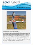
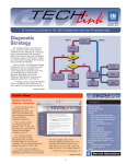
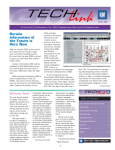
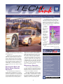
December 2000
Volume 2, No. 12
used a stand-alone module.
The EBCM controls current flow
through the Magnasteer electromagnetic
coil, both the amount (amperage) and
the direction (polarity). Pulse width modulation is used to vary the voltage and
the resulting current flow. Current varies
between -2 and +3 amps.
Current
flows from
the controller
to the
Magnasteer
rotary actuator, mounted
in the steering rack
assembly. It
consists of
two magnets,
a permanent
magnet and
an electromagnet.
The electromagnet
receives the variable current. The permanent magnet has 30 poles spaced at 12°
intervals.
There are two separate sets of pole
continued on page 2
Magnasteer power steering is now
available on a wide range of cars from all
five GM divisions.
Magnasteer is an electronic device
added to conventional power rack and
pinion steering to vary the amount of
effort required to steer the car, dependent on vehicle speed. At low speeds,
steering effort is lower, for ease in parking. As speed increases, steering effort
is increased, for greater road feel.
Additionally, on some models, evasive
steering maneuvers also affect steering
effort.
Conventional Rack and
Pinion Power Steering
Operation
An understanding of Magnasteer
begins with an explanation of conventional power steering. In a conventional
power rack and pinion steering gear, the
steering input shaft is joined to the pinion by a torsion bar inside the valve
body. Whenever the steering wheel is
turned, the torsion bar twists slightly (a
degree or two) as the steering effort is
applied through the pinion to the resistance offered by the front wheels. The
two halves of the spool-type hydraulic
control valve are attached, one at each
end of the torsion bar. So, when the torsion bar is twisted, the spool halves are
realigned relative to each other and fluid
is permitted to flow through to the steering gear. Steering effort, determined by
the stiffness of the torsion bar and pump
flow, is constant at all times.
Magnasteer Operation
In a car equipped with Magnasteer,
the basic power rack and pinion steering
system continues to function normally.
Magnasteer does not affect flow, so normal boost is available at all times.
The basic Magnasteer system varies
only the driver’s steering effort, regulated according to vehicle speed. In current
production, Magnasteer is controlled by
the Electronic Brake Control Module
(EBCM); a few models in past years
1
Contents
Magnasteer ® Power Steering . . . . . . . . . . . . . .1
Power Steering Analyzer . . . . . . . . . . . . . . . . . .3
Identifying OE Engine Oil Filters . . . . . . . . . . . . .3
Water Inside Rear Spoiler . . . . . . . . . . . . . . . . .3
RKE Receiver Module Location . . . . . . . . . . . . . .3
Engine Performance Diagnosis . . . . . . . . . . . . . .4
Thermistors . . . . . . . . . . . . . . . . . . . . . . . . . .4
Cruise Control Cancels Intermittently . . . . . . . . .5
Xtreme Pickup Decal Installation . . . . . . . . . . . . .5
GM Service Clubs, Part 2 . . . . . . . . . . . . . . . . .6
Service Operations Advisory Group . . . . . . . . . . .6
TAC Tips . . . . . . . . . . . . . . . . . . . . . . . . . . . . .7
Tacker Sensitivity to Vibrations . . . . . . . . . . . . . .7
Service Bulletin Based on Reader Information . . . .7
Bulletins . . . . . . . . . . . . . . . . . . . . . . . . . . . . .8
Thanks for Information . . . . . . . . . . . . . . . . . . .8
Tire Pressure Monitor Tool . . . . . . . . . . . . . . . .8
Service Operations
continued from page 1
pieces, inner and outer, which close the
magnetic field. The permanent magnet
sits between the inner and outer poles of
the electromagnet.
The strength and polarity of the magnetic field in the electromagnet determines the effect Magnasteer has on
steering input.
At zero mph, negative current flows
thorough the electromagnet, and the
magnets begin to repel each other. The
more the magnets repel each other,
steering
effort
decreases,
as though
the torsion
bar became
lighter. This
is the
desired
condition at
low road
speeds,
such as
parking.
At
about 45
mph, there
is no current flow
through the
magnetic
coil, so steering effort is determined only
by the torsion bar and pump flow.
Above 45 mph, current flows in a
positive direction and increases as speed
increases. The electromagnetic pole
pieces and the permanent magnet attract
each other, which raises the torsional
rate of the steering gear, and adds to
steering effort. It’s as though the torsion
bar gradually became stiffer. This provides greater road feel.
Service
Diagnosis may be required, based on
one of three driver concerns.
1. Light steering effort at all speeds
2. Heavy steering effort at all speeds
3. Erratic steering effort levels at various speeds
Systematic diagnostic procedures are
presented in the appropriate service
manual.
NOTE: The Magnasteer system on
some vehicle lines can be recalibrated for
steering effort, using the Tech 2. There
are three settings: Factory, More Firm,
and Less Firm. On those vehicles where
recalibration is available, use this feature
only at the customer’s request. Refer to
the appropriate service manual for
details.
The Magnasteer activator is serviceable only by replacing the entire steering
rack assembly. Individual components are
not available.
Electronic Testing
Malfunctions in the electronic portions of the Magnasteer system are diagnosed using the Tech 2 to access diagnostic codes.
Only a highly informed driver could tell
the difference between systems.
Regardless of which version of
Magnasteer is installed on a vehicle, the
effect on the driver is the same -- steering
effort is noticeably easier at low speeds
and increases as the car goes faster.
Publisher & Editor:
Mark Stesney
GM Service Operations
[email protected]
Technical Editor:
Jim Horner
[email protected]
1-248-816-3641
Production Manager:
Marie Meredith
Desktop Publishing:
FAX number:
1-248-649-5465
Write to:
TechLink
PO Box 500
Troy, MI 48007-0500
Magnasteer MAGe
In this version, the Magnasteer effect
depends entirely on road speed, and
there is no change during evasive maneuvers.
VSSM Communications
Gracemary Allen
Greg Szpaichler, MediaWurks
[email protected]
MAGe
An added feature on some
Magnasteer systems comes into play in
a skidding condition. If excessive lateral
G-forces are detected, Magnasteer
increases steering effort, to encourage
the driver not to oversteer.
The latest version of Magnasteer eliminates the permanent magnet. In this
form, one pole piece of the electromagnet is mounted to the input shaft and the
other to the pinion shaft. At the lowest
speeds, there is no current flow through
the electromagnet, and steering effort is
dependent only on the stiffness of the
torsion bar. As speed increases, current
flow through the electromagnet increases, and steering effort increases.
GM TechLink is a monthly magazine for
all GM retail technicians and service
consultants providing timely information
to help increase knowledge about GM
products and improve the performance
of the service department. This magazine is a companion to the GM Edge
publication.
Hydraulic Testing Tips
The power steering system section of
the service manual presents a test procedure for the Magnasteer hydraulic components, which are the same as those
used in non-Magnasteer systems. Use of
tester J-44721 permits you to test the
operation of the steering gear and the
pump, and identify system restrictions.
– Ken Hill and Scott Bower contributed to
this article.
General Motors service tips ar e
intended for use by professional technicians, not a "do-it-yourselfer." They
are written to inform those technicians of conditions that may occur on
some vehicles, or to provide information that could assist in the proper
service of a vehicle. Properly trained
technicians have the equipment, tools,
safety instructions and know-how to
do a job properly and safely. If a condition is described, do not assume
that the bulletin applies to your vehicle or that your vehicle will have that
condition. See a General Motors dealer servicing your brand of General
Motors vehicle for information on
whether your vehicle may benefit from
the information.
Inclusion in this publication is not necessarily an endorsement of the individual or the company.
Copyright© 2000 General Motors Corporation
All rights reserved.
2
Return to page 1
Tools
Power Steering
Analyzer
Power Steering Analyzer J-44721, a
new essential tool, has been released by
Kent-Moore and will be in your
dealership soon. You’ll need it to
perform the power steering system diagnostic procedures in the
2001 service manual.
In addition to
the pressure
gauges, the analyzer contains a flow meter to measure
fluid flow under various conditions. And,
a valve permits adding a variable restriction to the circuit as called for in the service manual procedures.
The power steering system
must be warmed up by allowing
the engine to idle until it reaches
operating temperature.
If you already have the
J-25323, you can convert it to
become the J-44721 by adding the
components in kit J-25323-UPD.
Identifying OE
Engine Oil
Filters
If you question
whether the proper
routine maintenance
has been performed on
a vehicle, there are several things to look at.
One way to check if
routine maintenance
has been performed is
to identify the current
engine oil filter. If the
vehicle still has the
original equipment (OE)
oil filter after 20,000
miles, for example, routine maintenance may
not have been performed.
For 1998-2001 models equipped with a
GM Powertrain produced engine, there are
several ways you can
distinguish between
OE oil filters (factory
The analyzer is installed in the pressure line between the pump and the
steering gear. If the system has been
repaired, accurate diagnosis
requires that the system be bled
of air before beginning the test.
Also, any air introduced during the installation of the analyzer must be purged. Maintain the
proper level of fluid in the reservoir during the test; use only
approved power steering fluid.
The J-44721 analyzer is an
updated version of the J-25323
analyzer, which was previously
essential for Oldsmobile dealers
and available to all dealers.
The major difference between
the two analyzers is that the
J-44721 is equipped with two pressure
gauges instead of one, for accurate readings at both low and high pressures.
Also, the J-44721 includes an adapter
assortment that permits using the analyzer on all current GM cars and trucks.
J-44721 permits you to test the operation of the steering gear and the pump,
and identify system restrictions that may
be present in the pressure or return
lines.
Testing Tips
The power steering system section
of the service manual provides a test
procedure for the power steering system
hydraulic components. Use of analyzer
installed) and non-OE
oil filters (which have
been installed after the
vehicle was new).
This information
applies to all vehicles
except Saturns,
Chevrolet Metro,
Tracker and Prizm,
Cadillac Catera, and
3.5L V6 (LX5) engines
with the PV6 cartridge
type filter.
1. OE filters have a
small part number label
(25.4mm x 35mm).
Non-OE filters have a
larger label (39mm x
60mm) that includes
tightening instructions.
2. OE filters have a
seal with a red teflon
coating. Non-OE filters
have a black, uncoated
seal.
3. All filters have an
ink-stamped 6 digit
Julian date code at the
wrench flat end of the
filter (065003 = March
5, 2000, 3rd shift). OE
filters have an "OE" at
the end of the date
code. Non-OE filters do
not.
For Chevrolet Metro
and Tracker models,
the original filters have
Suzuki printed on them,
and replacement filters
do not. On Chevrolet
Prizm models, the original filters are black with
white Japanese characters, and a caution in
English. Replacement
filters do not have any
Japanese writing.
The next time routine maintenance
comes into question,
identifying the engine
oil filter may help you
determine if scheduled
maintenance has been
performed.
– Rich Burrell
The hydraulic tests require
you to observe pressure and
flow readings under various
operating conditions and engine
speeds. Never close the control valve on
the analyzer unless told to do so by the
procedure, and never leave the valve
completely shut for more than 5 seconds
at a time.
– Matt Stange contributed to this article
Water Inside Rear Spoiler
A water sloshing sound may be heard coming
from the rear spoiler of some 2000 Pontiac Grand
Prix models when the trunk lid is raised and lowered.
If it is confirmed that water is inside the spoiler, remove the spoiler and look for a small hole on
both the left and right underside of the spoiler
approximately 16 inches inboard from the outboard tip of the spoiler, and two a couple of inches from the rear edge. The small holes may be
covered by pieces of tape that should be painted
the same color as the spoiler.
Remove the tape to drain the water from the
spoiler. Do not retape over the holes. Once the
water is removed from the spoiler, reinstall the
spoiler on the vehicle.
RKE Receiver Module Location
The Remote Keyless Entry (RKE)
module/receiver has been relocated on 2001
Pontiac Grand Prix models. The module is now
located at the cross car beam in front (windshield
side) of the passenger side air bag. It was previously located behind the Driver Information
Center.
At its new location, the RKE module is
accessed by removing the defroster grill. To
remove the module, it must be disengaged from
the retaining tabs by moving it to the left and
then pulling up.
– Fred Tebbets
3
Return to page 1
Engine Controls
between
frequency
and duty
cycle; analog and
digital;
PERFORMANCE
DIAGNOSIS
2. knowledge of
electrical basics
Think of the best
engine performance
technician you’ve ever
worked with -- how is
this person different
from you? Likely, you
both have many of the
same things available.
3. knowledge of indi
vidual components
- essential tools
such as the Tech 2 and
Fluke 87 DVOM,
absolute necessities
for this type of work.
- the same diagnostic resources, such
as SI2000 for bulletins,
preliminary information
and service information.
- access to
Technical Assistance
for those tough cases.
Probably the only
thing differentiating
you from this person is
among these four
things, listed in order
of importance:
1. diagnostic strategy
Class 2 and UART;
capacitance and inductance
4. extra tools
Here they are in
detail.
Get the picture?
Diagnostic
Strategy
Individual
Component
Knowledge
Strategy Based
Diagnostics (SBD),
along with a complete
understanding of the
service resources
available, are critical in
the success of any
technician. These skills
are the most important
to learn, above all else.
Service manual
diagnostics for individual components are
the front line of
defense. You should
always refer to the
diagnostic charts associated with various
fault codes or symptoms.
Electrical Basics
But, you’ve truly
mastered a component only when you
begin to understand
the importance of the
voltage level or frequency you’re about to
measure, or the scan
data you’re about to
read, and the potential
causes for variations
as you read each step.
Among the essentials you need to
know:
- the relationships
between volts,
amps and ohms
- schematic reading
skills
- the differences
THERMISTORS
Engine Coolant Temperature Sensor
(ECT) -- affects fuel delivery, idle, TCC
apply, EGR, cooling fans, EVAP,
knock/ignition control
Intake Air Temperature Sensor
(IAT) -- affects air density air/fuel
adjustments, spark adjustments
Transmission Fluid Temperature
Sensor (TFT) -- affects TCC apply, line
pressure
Extra Tools
Extra tools are
something you can
buy any time, once
you understand their
benefits. Buying a tool
before realizing its
potential is a bad idea.
Also realize that mastering diagnostic strategy, electrical basics
and component knowledge should come
before you even consider buying advanced
tools.
The accompanying
article is the first of
Temperature vs. Resistance Values
(approximate)
(first in a series)
A thermistor is a temperature-sensitive resistor. The thermistors used in
GM vehicles have a negative temperature coefficient, meaning the resistance
goes down as the temperature goes up.
Here are some thermistors used by the
Powertrain Control Module (PCM), along
with their role in PCM decision making.
There are principles
behind the names of
various engine sensors
and output devices.
You’re on the road to
higher understanding
once you realize that a
component is not just
an Intake Air
Temperature Sensor
but a thermistor, or not
just an Exhaust Gas
Recirculation Valve but
a solenoid. This type
of knowledge comes
from training or experience.
°C
°F
Ohms
100
212
177
90
194
241
80
176
332
70
158
467
60
140
667
50
122
973
40
104
1459
30
86
2238
20
68
3520
10
50
5670
0
32
9420
-10
14
16180
-20
-4
28680
-30
-22
52700
-40
-40
100700
several to be devoted
to engine controls.
With every coming
article, we intend to
feature a specific powertrain input or output
device. We’ll answer
many questions,
including:
- What type of
device is it?
- What is its purpose?
- How is built?
- What does its circuitry look like?
- How is this component best diagnosed? (scan tool,
DVOM)
The purpose of
these articles is to
help you develop the
skills and knowledge
you need, to become
the performance technician that others consider the best.
Concentrate on
whichever of these
four things you need
to work on, to differentiate yourself from the
others. Only you know
what they are.
Engine Oil Temperature Sensor
(EOT) -- affects engine oil life monitor
calculations
Note the change in resistance for
temperature is not linear. For example,
the difference in resistance between
–40 and –22 degrees F, a change of 18
degrees, is 48,000 ohms. The change
between 194 and 212 degrees, also 18
degrees, is only 64 ohms.
All thermistor-based sensors have
two wires.
Circuit basics can be explained using
the IAT diagram. The PCM supplies a 5volt signal through a dropping resistor
and out to the IAT on the tan wire. The
IAT provides a ground path through the
sensor and back to the PCM on the
black wire. Note that this sensor ground
is often shared by other components
and can be influenced by a shorted condition within them.
4
Return to page 1
tions to just one resistor. This strategy
is to maximize the accuracy of the sensor for higher engine temperatures and
was necessitated by the resistance
characteristics of the sensor. This
results in an obvious shift in voltage at
the 122 degree mark. At that point, the
voltage jumps up immediately from
below 1 volt to about 3.5 volts. This
becomes important to know if you use
a scope to diagnose an ECT circuit live
or when using a scan tool on a truck
product that includes ECT voltage on
the data list.
When the IAT sensor is very cold
(high resistance) it acts like a roadblock
for the flow of electrons to ground. The
IAT sensor signal in the PCM is high.
As the IAT sensor heats up, the resistance drops, and more voltage is
dropped across the sensor. The circuit
is very simple.
Circuitry on a thermistor-based sensor is very easy to test. On a cold
engine (one that has not run within six
Don’t forget the potentially shared
ground paths with other sensors.
Thermistors rarely fail for reasons other
than circuitry. Terminal corrosion at ECT
sensors is a common cause for failure.
Connector and sensor replacement is
typically necessary.
Sensor wiring for an ECT sensor is
unique. Earlier, we mentioned the difference in resistance changes on the
upper and lower end of the tempera-
It’s unlikely that you’re going to get
a P0118 ECT sensor code to work on
tomorrow to exercise your new knowledge. But, the sooner you practice, the
more likely that you will retain it. So get
out there and give those Tech 2 circuit
checks a try.
Be on the lookout in future issues
for more articles on Performance
Diagnosis.
- Craig Blake
Cruise Control Cancels
Intermittently
hours), scan data for ECT and IAT
should be within ten degrees
Fahrenheit.
If a malfunction in the circuit is suspected, observe the scan tool parameter with the sensor unplugged. The
unplugged sensor will create very high
(infinite) resistance and the scan tool
should show a very cold temperature
(approximately -40 degrees Fahrenheit).
If this does not occur, check the sensor
wire for open circuit voltage with a
Fluke 87. It should be 5 volts. Less
than 5 volts indicates a short to ground
condition or a bad PCM.
ture scale. In the PCM, there are two
paths for the 5-volt reference. When
the engine temperature is below 122
degrees Fahrenheit, it travels through
two dropping resistors. When it reaches 122 degrees Fahrenheit, it transi-
The cruise control may cancel
intermittently when using the left
turn signal on some 2000 Buick
Century and Regal models. The
resume function is still operational
after the cruise control cancels.
This condition may be caused by
an internal switch in the multifunction lever causing a backfeed to the
cruise control module. The module
thinks it has seen a brake switch
input signal and cancels the cruise
control set speed. If this condition is
verified, replace the multifunction
lever. Parts are available through GM
SPO.
– Wayne Zigler
Xtreme Pickup Truck
Decal Installation
Xtreme models are shipped with
an Xtreme decal that fits the windshield. This decal should not be
installed during pre-delivery,
because it may not be legal to do so
in some states. Leave the decal in
the vehicle; installation is at the customer’s discretion.
- Dan Oden
The next quick circuit check
involves a test lead outfitted with two
appropriate male terminals. Use this
test lead to jump the two sensor wires
at the unplugged connector and
observe the scan tool parameter. This
low resistance connection should yield
a very high temperature (260 degrees
Fahrenheit or above). Failure of this test
indicates ground circuit problems.
5
Return to page 1
GM Service
Clubs, Part 2
In the November issue of GM
TechLink, we listed a number of
GM service clubs around the
country that meet to talk about
the service issues that dealership
service departments face each
day.
This interactive communication is one of the benefits for service managers who attend a local
service club meeting. The clubs
provide a way for service managers to access a wide array of
information from other dealership
service departments as well as a
number of GM sources.
Following is a list of additional
GM service clubs. GM supports
local service clubs and many GM
representatives attend the club
meetings. For more information
about GM service clubs, contact
any of the clubs listed here.
Service
Operations
Advisory Group
GM Service Operations relies
on input from a number of
sources to assess the opinions
and needs of retail dealership service departments across the
country. One of these sources is
a group of eight technicians, recommended by their TechLine representatives in the five regions.
This advisory group serves as
a sounding board for service
issues, and their feedback is forwarded to the appropriated
department within GM for evaluation. Their suggestions may also
lead to future articles in GM
TechLink.
Service Operations would like
to extend their thanks to the present members of the advisory
group, listed here.
SOUTHEAST REGION
Atlanta Service Club
Contact: Jeff Burns
Jerry Brown Chevrolet,
Buford, GA
770.945.4981
Metrolina GM Service
Managers Club
Contact: Tommy Cross
Dale Earnhardt Chevrolet,
Newton, NC
704.465.3251
Piedmont Service
Managers Club
Contact: Jeff Keith
Modern Chevrolet, Winston
Salem, NC
336.722.4191
Inland Valley Service
Managers Club
Contact: John Arnold
Beach City Chevrolet, Long
Beach, CA
562.597.6633
WESTERN REGION
Central Coast Service
Managers Club
Contact: Steve Montana
Rio Vista Chevrolet,
Buellton, CA
805.688.3231
LOCAR Club
Contact: Gary Loy
Cormier Chevrolet, Long
Beach, CA
310.830.5100
Las Vegas Service
Managers Club
Contact: Tom Hudlick
Cadillac West, Las Vegas,
NV
702.873.8888
Blue Ridge Service and
Parts Managers Club
Contact: Sam Lilly
Royal ChevroletOldsmobile-Cadillac,
Lynchburg, VA
804.237.9400
San Diego Service
Managers Club
Contact: Earl Ashbury
Weseloh Chevrolet,
Carlsbad, CA
760.438.1001
Triangle Service
Managers Club
Contact: Tony Crabtree
Don Lacefield ChevroletBuick, Hillsborough, NC
919.732.2151
Dennis Murphy
Master Technician
Superior Oldsmobile, Cadillac,
GMC
Paul Richards and Richard
Mcintyre, owners
Brighton, MI
George Reed
Shop Foreman/Asst. Service
Manager
Fischer Chevrolet/Oldsmobile
Bob Fischer, president
Titusville, FL
Max Millender
ASE Master Technician
Ewing Buick GMC Pontiac
Fin Ewing, dealer principal
Plano, TX
Jon Finefrock
Master Technician
Faulkner Chevy, Inc.
Judith Faulkner, owner
Lancaster, PA
Seattle Service Club
Contact: Roger Sideck
Bill Hazelett Chevrolet,
Kent, WA
800.638.7222
Inland Empire Fixed
Operations Club
Contact: Dale Poole
Chipman & Taylor Motors,
Spokane, WA
509.334.3555
Salt Lake Service Club
Contact: Ty Johnson
Jerry Seiner Buick-PontiacGMC, Inc., North Salt Lake, UT
802.298.5163
Lance Mossman
CMAT, L1
Applegate Chevrolet
Jim Applegate, owner
Flint, MI
Dennis Burtness
Shop Foreman
Burtness Chevrolet
John Bowditch, owner
Orfordville, WI
Mark Haynes
ASE Master Technician
Steve Coury Buick-Pontiac-GMC
Steve Coury, owner
Cottonwood, AZ
Joesph Herring
ASE Master Technician
Harold Chevrolet
Jim Lupient, owner
Boomington,MN
6
Return to page 1
TAC Tips
2001 Pontiac
Aztek Requires
Windshield
Removal To
Replace
Evaporator
Core
ing the evaporator
core, some of the
bolts retaining the
cross vehicle beam to
the hinge pillars cannot be removed due
to contact with the
windshield. The bolts
are approximately 810 inches in length.
About 3-4 inches will
Some information
was omitted from
SI2000. When remov-
Tracker
Sensitivity to
Tire Vibrations
The 1999 Tracker
became more sensitive to
wheel and tire imbalance
and tire radial force varia tion, due in
part to the
design change
to rack and pin ion steering.
OEM tire specifications and
the tire and
wheel matching and balancing operations
at assembly
were made
more stringent.
In 2000, Tracker design
changed to a hub centered
wheel which eliminated
the vibrations caused by
off-center mounting of the
wheel. The Tracker, however continues to be sensi tive to tire induced vibra tions, and customers may
benefit from following the
TPC Specification recommendation.
Steering Wheel
Shake/Vibration After
Tire Rotation
After tires are rotated,
steering wheel vibration
concerns may suddenly
reappear. The 1999 Tracker
uses a lug centered wheel,
and relies upon the lug nut
taper-to-wheel hole taper
interface to center the
wheel and tire assembly
on the hub. Steering
wheel vibrations induced
by off-center wheel installations may
be significantly reduced
with the following procedure.
Start by
ensuring that
tire air pressure is correct.
Balance the wheel and
tire assembly using electronic balancing equipment
which also measures radial
force variation. Wheel and
tire assemblies which
have a radial force varia tion reading of greater
than 9 pounds should be
evaluated for cause, and
may require replacement
of the wheel or tire.
Follow this procedure
to install wheel lug nuts to
aid in centering the wheel
on the hub:
Rotate the hub to posi tion two studs of the five
at the top of the circle and
remain in the
hole when they
contact the
windshield.
The windshield
will need to be
removed to complete
the repair. Take care
to avoid breaking the
windshield during
removal.
– GM Technical
Assistance
Tire Size
Place the wheel on all
five studs, and spin on the
top two lug nuts finger
tight.
Service Operations, working with
Engineering, investigated the condition
and found that Zaffino’s suggestion
worked.
Rotate the wheel 180°
so the opposing one stud
is at the top of the circle,
and spin the lug nut on finger tight.
The result is service bulletin 00-01-39001. The bulletin points out that a washer,
P/N 5462496, should be installed between
the right-hand air outlet duct housing and
the control lever at the pivot point in order
to increase the tension to hold the air outlet shut-off door open. This will keep the
shut-off door in the open position when
the blower fan is on high while still allowing the thumbwheel to rotate easily.
Using hand tools, tighten these three points of
the lug nut pattern to just
past finger tight, which will
center the wheel on the
hub.
Install the remaining
two lug nuts and, using a
star pattern, evenly torque
all lug nuts to the correct
value.
Steering Wheel
Shake/Vibration After
Tire Replacement
The OEM tire has a
Tire Performance Criteria
Specification (TPC Spec)
number on the sidewall.
Replacement tires should
carry the same TPC Spec
number. If not, different or
unwanted ride characteristics, such as steering
wheel shake or vibration
may be induced.
– Don Sherman con tributed to this article.
B
26 PSI
180 kPa
1043MS
4WD
base
Uniroyal
P205/75R15
Tiger Paw
26 PSI
180 kPa
1031MS
Zaffino says that when he diagnosed
the condition, he knew that the tension
needed to be increased somehow on the
air outlet door.
“It needed just a little extra tension,
but there’s not much space in there. I first
tried to place foam in the vent, but it
would tear, and it needed to be thicker.
Then I tried fabricating a shim that was cut
to size. It provided the tension needed and
was held in place by the vent.
“I’m proud that the information was
used by GM. I’m glad I could help.”
Now, will all reader suggestions
become bulletins? Probably not. But if you
have a suggestion for a product condition,
try submitting a VME product report.
This system allows you to leave a
voice mail message regarding any current
product condition you’ve come across that
you think GM engineers should know
more about. To submit a product report,
call 1-888-274-4185. When you are asked
to input the mailbox number, use the following:
- Mailbox 32000, Truck
Temperature
Goodyear P195/75R15
Wrangler
ST
The DeVille’s right-hand HVAC air outlet vent would close while the blower is
on high, and Gary Zaffino, a 21-year veteran technician at Massey Cadillac in
Orlando, FL had come up with the fix.
parallel to the road sur face.
Pressure TPC Spec Treadwear Traction
2WD
base
GM is listening. Case in point: a suggested repair for 2000 Cadillac DeVille
models was sent in to us here at GM
TechLink.
Zaffino suggested fabricating a shim
that could be installed on the left and right
side of the vent. This would increase the
tension on the blower door and prevent it
from closing while the blower was set on
high.
OE information for the 1999 Tracker:
Model Brand
Service Bulletin
Based on TechLink
Reader’s Information
340
480
B
B
B
- Mailbox 32001, Car and U-Van
- Mailbox 32002, Powertrain
GM values input from the field on
product concerns. Your insight can help
GM increase vehicle quality and owner
satisfaction.
7
Return to page 1
Bulletins –
November 2000
This review of service bulletins
released through mid-November lists
the bulletin number, superseded bulletin number (if applicable), subject
and models.
GENERAL INFORMATION:
00-0089-024; September, 2000
Bulletin Summary; 2001 and Prior
Passenger Cars and Trucks
Warranty; 1996-2001
Passenger Cars and
Light Duty Trucks
BRAKES:
99-05-25-003A; Cancellation of DBC 7
Diagnostic Assistance and Parts Retur n
Program; 1999 Buick Century, Regal;
2000 Chevrolet Cavalier, Impala, Malibu,
Monte Carlo, Venture; 2000 Oldsmobile
Silhouette; 2000 Pontiac Sunfire,
Montana
HVAC:
ENGINE/PROPULSION
SYSTEM:
00-01-38-008; A/C Inoperative (Repair
Wires and Reroute Harness); 2000
Chevrolet and GMC S Truck Models With
2.2L Engine (VIN 4 -- RPO LN2),
Shreveport Assembly, Prior to VIN
Breakpoint Y8302995
99-06-01-002E; Exchange Program for
2001 Model Year; 2001 Chevrolet and
GMC C/K and G Light Duty Models,
Chevrolet and GMC B7, C6, C7 Medium
Duty Models with 8.1L Engine (VINs E, G
-- RPO L18)
00-01-38-009; Refrigerant Dye Added
to A/C System at Assembly Plant; All
2001 Passenger Cars
00-06-01-022; Engine Noise (Replace
Belt Tensioner); 1999-2001 Chevrolet
Tracker with 2.0L Engine (VIN C -- RPO
L34)
SUSPENSION:
00-06-03-008; Battery Testing Using
Essential Tool J42000 Battery Tester;
2001 Corvette
99-03-11-001A; Cancellation of
Diagnostic Assistance and Parts
Restriction Program for Delphi Chassis
Suspension Components; 1999 Chevrolet
and GMC C1/K1 Models (Silverado and
Sierra) with MSR (Manual Selectable
Ride) RPO ZX3
00-03-08-003; Revised Lower Control
Arm Removal/Installation Procedure and
Fastener Tightening Specifications; 19972000 Chevrolet Malibu, Oldsmobile
Cutlass and Alero, Pontiac Grand Am
00-03-10-003A; General Motors Tire
00-06-04-042; Malfunction Indicator
Lamp (MIL) On With DTC P0446 Set
(Reprogram PCM); 1998-2000 Chevrolet
and GMC K/K Models with 7.4 L Engine
(V(N J -- RPO L29) with California
Emissions (NB6)
00-06-04-044; Engine Hesitates, Stalls
and/or Will Not Start (Replace Modular
Fuel Sender Strainer); 2000 Chevrolet
Cavalier, Malibu; 2000 Oldsmobile Alero;
2000 Pontiac Grand Am, Sunfir e
Thanks for the
Information
TRANSMISSION/TRANSAXLE:
00-07-30-017; Allison Automatic
Series 1000 Transmission Exchange
Program (Early Concern Detection); 2001
Chevrolet and GMC C/K 2500/3500
Pickup Models with Allison Automatic
Series 1000 Transmission (RPO M74)
BODY AND ACCESSORIES:
00-08-42-007; Stop/Tail Lamp(s)
Inoperative or Intermittent and/or Water
in Lamp (Replace Circuit Board/Gasket
and/or Lamp Assembly); 1997-1999
Chevrolet Malibu, 1999-2000 Pontiac
Grand Am
00-08-49-011; Availability of Smoker’s
Package; 2001 Chevrolet Venture, 2001
Oldsmobile Silhouette, and 2001 Pontiac
Montana
00-08-50-014; Driver’s Bucket
Seatback Movement During Braking
(Replace Seatback Recliner Assembly);
2000 Chevrolet and GMC C/K Pickup
(Silverado and Sierra) and Utility
(Suburban, Tahoe, Yukon, Yukon XL)
Models
00-08-52-004A; Intermittent Operation
of Remote Keyless Entry System
(Replace Instrument Panel Cluster); 2000
Chevrolet Impala, Monte Carlo
00-08-61-003; Clunk/Pop Noise From
Front Of Vehicle (Shim Rear
Frame/Cradle Mounts); 2000 Chevrolet
Impala, Monte Carlo
00-08-110-004; Rear Quarter Trim
Gaps to the B-Pillar (Insert Screw); 19982000 Chevrolet Camaro (coupe); 19982000 Pontiac Firebird (coupe)
GM Service Operations sent
out a questionnaire asking
about the Tech 2 and Electrical
Service Information in late
September to every dealership
in the U.S. The questionnaire
was also distributed throughout
GM dealerships around the
world.
The efforts of everyone
who completed a questionnaire are appreciated. All of
the data is being compiled
and a summary of the results
of both questionnaires will be
put together. With this feedback from actual users of the
tools, future product improvements will be made based on
what technicians want and
need.
The goal was to gather
feedback about the operation
and use of the Tech 2 as well
as GM Service Information. The
response has been overwhelming and GM Service Operations
would like to say “Thanks.”
Thanks to all who
responded to the questionnaires and look for more
details soon about future
enhancements based upon
your feedback.
– Jeff Flood
ERRATA
2001 Tire Pressure
Monitor Tool
An illustration in the
November, 2000 issue of GM
TechLink was incorrect. The
tool number J-41760 is correct, but this is what the Tire
Pressure Sensor Programmer
tool looks like.
8
Return to page 1