1
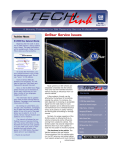
December 2001
Volume 3, No. 12
A monthly publication for GM Dealership Service Professionals
Quadrasteer™ Rear Wheel Steering Introduced
A revolutionary new rear wheel steering
system is standard equipment on the 2002
GMC Sierra Denali pickup truck.
Quadrasteer reduces the diameter of the
turning circle by 3 m (10 feet), so it’s
comparable to that of a compact car. In
addition, it contributes to stability on the
highway and maneuverability when towing a
trailer.
All of this is accomplished by a rear axlemounted rack and pinion steering gear operated by a computer-controlled electric motor.
Operation
Quadrasteer operates in three ”phases:”
Negative Phase -- At low speeds, up to 72
kph (45 mph), the rear wheels steer in the
opposite direction of the front wheels
Neutral Phase – At moderate speeds,
about 72 kph (45 mph), the rear wheels
remain straight. This is also the failsafe
phase in case of system problems.
continued on page 3
Techline News
32 MB CARD
one J-45080 32 MB card to replace the 10
MB card.
TIP: See the 32 MB article in the April,
2001, issue of TechLink on the
service.gm.com website.
TIP: The Tech 2 requires a linear flash
card. The low-priced 32 MB strata cards
available on the internet will not work.
The new 32 MB card is shipped with
startup software installed, and should be
inserted in Slot 1, closest to the screen.
TIP: When updating the 32 MB card for
the first time and using TIS 2000,
remember to select the Custom Mode.
In the April, 2001, issue of TechLink,
you learned that the days were numbered
for the 10 MB (megabyte) card in your Tech
2. With the ever-expanding use of on-board
computers, there’s no longer enough room
on the 10 MB card.
Beginning last April, all new Tech 2s are
being shipped with a new 32 MB card
installed. Also, each dealership received
You MUST have the 32 MB card
installed before updating your Tech 2 again.
The update will be broadcast on GM
ACCESS on January 14, 2002, and will be
included on CD no. 1 for 2002, shipped on
January 17, 2002. This update WILL NOT
fit on the 10 MB card.
What Will Happen to the 10 MB
Card?
It’s recommended that you keep the
continued on page 2
1
Contents
Quadrasteer Rear Wheel Steering Introduced . . .1
Techline News
32 MB Card . . . . . . . . . . . . . . . . . . . . . .1
Making a Duplicate Card . . . . . . . . . . . . . .2
Freeze Frame . . . . . . . . . . . . . . . . . . . . . .2
Class 2 Tip of the Month . . . . . . . . . . . . . . . . .2
DVD Navigation System for 2002 . . . . . . . . . . .4
Proper Removal of O2 Sensors . . . . . . . . . . . .5
Top Post Battery Introduced . . . . . . . . . . . . . . .6
Tech Tips
Park Brake Specifications . . . . . . . . . . . . . .3
Noise in Strut Support . . . . . . . . . . . . . . . .6
Ignition Key Binds . . . . . . . . . . . . . . . . . . .6
Cruise Control Switch Inoperative . . . . . . . .6
AWD Rear Drive Axle Fluid Requirements . . .6
Allison LCT 1000 Transmission . . . . . . . . . . . .7
Test Lamp Technology . . . . . . . . . . . . . . . . . . .7
Bulletins . . . . . . . . . . . . . . . . . . . . . . . . . . . .8
Service Operations
Techline News
continued from page 1
latest update on the card until told to do
otherwise. GM Service Operations recently
conducted a survey of Tech 2 users, asking
for ideas about what to do with the 10 MB
card. These ideas and comments are being
reviewed, and you will be notified as soon
as a decision is made.
MAKING A DUPLICATE CARD
Once you have updated a card, you can
use this timesaver “copycard” procedure
to make duplicates.
One card (the source) has the
programming you want to copy onto the
other (the destination). You can can put
either card in either slot.
TIP: Be sure the cards are seated
properly. Improper seating will cause error
messages to appear. Also, use caution and
make certain that the card is properly
aligned with the guides in the Tech 2 card
ports. Failure to properly align the card
may damage the card or the Tech 2.
Follow this Tech 2 path:
1. Power up the Tech 2 to the log-on
screen.
Destination Card Too Small
Press [ENTER] to continue
(actually press the EXIT key)
Be sure you have 32 MB cards in both
slots, then start again.
FREEZE FRAME
In events that cause a vehicle’s
emission system to malfunction,
governmental OBD II requirements call for
a freeze frame failure to be recorded in the
PCM.
Data parameters are caught at the time
of failure and stored as a freeze frame. The
freeze frame remains until you erase it, or
it is overwritten by another event.
When you capture a freeze frame failure
record, you can download it to TIS 2000
and can view it. The data on PC screen
appears in the same order as data on Tech
2. You can store the freeze frame on your
PC, and can print it out for attachment to
the repair order, for future reference.
Here’s the path:
2. Use the shift key and the right or left
arrow key to select the source card (the
size of the card and version number will
be displayed on the screen).
TIP: Make sure you have the most
current update loaded to your PC. There
have been some improvements made to
this feature, including increasing snapshot
storage from 10 to 50 files.
3. Press [ENTER]
1. Connect Tech 2 to Techline terminal
4. F3: Tool Options (Main Menu)
2. Power up Tech 2
5. F7: Make Duplicate PCMCIA Card (Tool
Options)
3. On Techline terminal, select TIS 2000
6. The screen will confirm the direction the
data will flow. Press the COPY soft key
to begin the copy function.
5. Download freeze frame failure record
from Tech 2 to terminal
TIP: You cannot copy from a 32 MB to a
10 MB card. If you try to do so, this
message will appear:
Every controller on the Class 2 bus has its
own unique identification (ID) number. For
instance, the PCM's ID number is 016 and
the Instrument Panel's ID is 096.
Understanding this concept makes it easier
to understand the U-codes that will
periodically set.
For example, if a U1096 was set in the
PCM, the PCM lost communication with the
controller whose ID number is 096. In this
case, the Instrument Panel Cluster. Looking
at the service manual description for a
U1096, it states that it is a "Loss of
Communications from Instrument Panel".
Here's a list of the more common
controller and their IDs.
4. Click Snapshot icon
6. Now you can review, save, and print the
file.
– Thanks to Keith Armitage and Mark Stesney
PCM – 016
BCM – 064
SDM – 088
TCS – 040
EBCM – 041
IPC – 096
Radio – 128
HVAC – 153
RFA – 176
TIP: Although these IDs are standardized,
there may be variations depending on model.
When a U-code sets, keep in mind that
the controller setting the U-code is pointing
to the controller causing the problem. The ID
number given in the U-code tells you which
controller is at fault. The Tech 2 or SI2000
can tell you which controller the ID number
represents, but before long, it will become
second nature.
GM TechLink is a monthly magazine for
all GM retail technicians and service
consultants providing timely information
to help increase knowledge about GM
products and improve the performance
of the service department. This
magazine is a companion to the GM
Edge publication.
Publisher & Editor:
Mark Stesney
GM Service Operations
[email protected]
Technical Editor:
Jim Horner
[email protected]
1-248-816-3641
Production Manager:
Marie Meredith
Desktop Publishing:
Greg Szpaichler, MediaWurks
[email protected]
FAX number:
1-248-649-5465
Write to:
TechLink
PO Box 500
Troy, MI 48007-0500
GM TechLink on the Web:
http://service.gm.com
General Motors service tips are intended
for use by professional technicians, not a
"do-it-yourselfer." They are written to
inform those technicians of conditions
that may occur on some vehicles, or to
provide information that could assist in
the proper service of a vehicle. Properly
trained technicians have the equipment,
tools, safety instructions and know-how
to do a job properly and safely. If a
condition is described, do not assume
that the bulletin applies to your vehicle
or that your vehicle will have that
condition. See a General Motors dealer
servicing your brand of General Motors
vehicle for information on whether your
vehicle may benefit from the information.
Inclusion in this publication is not
necessarily an endorsement of the
individual or the company.
Copyright© 2001 General Motors Corporation
All rights reserved.
– Thanks to Mark Harris
2
Return to page 1
QuadrasteerTM
continued from page 1
Positive Phase -- At high speeds, above
72 kph (45 mph), the rear wheels turn the
same direction as the front wheels.
The Quadrasteer control module
determines the phasing and amount of rear
wheel steering based on the mode switch
setting, position of the steering wheel and
vehicle speed.
mode provides more positive phase
steering than the normal 4-wheel
steering, and at low speed, similar
negative phase steering as the normal 4wheel steering mode.
For maximum benefit, 4-Wheel Steer is
the recommended setting under most
conditions.
Diagnosis
Operating Phases
Detailed diagnostic
procedures are included in
SI 2000, and you should
always follow the steps in
the order published.
Because Quadrasteer is
part of the vehicle’s serial
data system, you’ll use your
Tech 2 to look for
diagnostic codes.
Rear / Front Stirring Ratio
TYPICAL ALGORITHM
Vehicle Speed (kph)
Negative Phase
Neutral Phase
When moving forward, the rear wheels
can steer up to 12 degrees. While standing
still, or in reverse, the rear wheels can steer
up to 5 degrees.
A feedback signal is sent from the rear
position sensor on the rack and pinion gear
to confirm rear wheel position.
Positive Phase
TIP: The handwheel
(steering wheel) position
sensor provides four
different outputs to the
control module. One is
analog and three are digital.
These outputs indicate
direction, speed, and
amount that the steering
wheel is being turned.
TIP: Ordinarily only one
mode indicator lamp is
illuminated at a time. If all
three are illuminated at the
same time, a wheel alignment is needed.
TIP: When the transmission is in neutral
for 4 seconds, the system will default to 2wheel steer until the shifter is placed into
gear again. This is to accommodate
automatic car wash requirements, and is
normal.
Service
Follow this path in SI 2000:
– 2002 GMC Sierra
– Steering
– Rear Wheel Steering
See SI 2000 for details. Here are some of
the highlights.
Lifting -- Because of the tie rod boots on
the rear rack and pinion gear, it’s important to
use caution when lifting with an in-ground
hoist or using jack stands. See SI 2000 for
details.
Alignment -- There are provisions for toe
adjustment only. Caster and camber are
fixed. SI 2000 explains the detailed
procedure for using the Tech 2 during the
”learn” procedure.
Quarter Shafts -- The quarter shafts are
equipped with constant velocity (CV) joints at
the outer ends only. The CV joints are
protected with rubber boots similar to those
on front drive axles.
Rear Actuator – In normal operation, noise
from the actuator should not be audible;
when the actuator is commanded by the
Tech 2, some operating noise is normal.
Steering Gear Motor – The electric motor
is serviceable separate from the steering
gear. When the motor is removed, the
planetary gear reduction set is exposed, so
care must be taken to avoid contamination.
Tech 2 Functions – You can use your Tech
2 to read operating parameters. Also, you
can command various functions so you can
observe operation. These include mode
indicator lamps, as well as steering in right
and left directions. See SI 2000 for details.
– Thanks to Jerold Miller
TIP: A yaw rate and lateral accelerometer
sensor is used only to monitor system
behavior; its output is not used for operation.
Mode Control Switch
Driver Control
A mode switch on the instrument panel
allows the driver to select from three modes:
– 2-Wheel Steer, in which only the front
wheels steer
– 4-Wheel Steer, in which rear steering is
enabled
Park Brake Specification
Affected vehicles:
1997-2001 4X4 (T) Chevrolet Blazer, S-10, GMC Envoy, Jimmy, Sonoma, Oldsmobile
Bravada
After resurfacing a park brake drum on the rear rotor of the above vehicles, the
maximum drum diameter should not exceed 191 mm (7.52 in).
– Thanks to Dan Oden
– 4-Wheel Steer Tow, in which rear steering
is optimized for towing. At high speed this
3
Return to page 1
DVD Navigation System for 2002
audible voice prompts, so the driver needs to
glance at the map only when necessary and
it is safe to do so.
TIP: The audible prompts are available in
English, German, Spanish, French, and
Japanese.
Display screen tilted open for access to DVD player
The navigation system provides voice
recognition for hands-free operation of nearly
every feature of the navigation system, radio,
CD player and DVD player. This feature
operates in the same way that the UV8
hands-free cellular telephone option works. A
press of a steering wheel control button
activates voice recognition. The system picks
up voice commands through a microphone
mounted in the rearview mirror, issues voice
prompts through the vehicle audio system,
and controls system functions. The system
will mute the radio during the voice
recognition process. The voice commands
include HELP prompts, which may be
activated at any time.
After hearing the system’s READY
prompt, a driver may say MAP HELP and the
system will state all commands available for
manipulating the map. Then saying ZOOM
OUT (for example) while voice recognition is
still active causes the system to perform that
navigation map command. After a few
seconds of silence, the voice recognition
feature times out, and radio or CD play
resumes.
For 2002, the Cadillac DeVille and Seville
will offer a new DVD Navigation System.
Although there are a lot of important new
features, perhaps the one the owner will
notice first is that it requires only one map
data disc to cover the entire continental US.
No more having to carry a selection of discs
and having to change them at state borders.
This is possible because a DVD has a
considerably larger storage capacity than the
previously used CDs. The disc is loaded
directly into the instrument panel unit,
instead of a trunk mounted unit as in 2001.
Quick Overview
As before, the new navigation system
uses a Global Positioning System (GPS)
receiver to determine the car’s location.
Then, using data from the DVD, it displays a
map of that location.
TIP: See the May 2001 issue of TechLink
for a description of the GPS principle, which
is also used by OnStar®.
TIP: Although both the DVD Navigation
System and OnStar use GPS technology,
they have separate antennas.
The navigation system GPS antenna is
located in the rear parcel shelf, where it has
an unobstructed view of the sky.
When the driver inputs a destination, the
equipment is able to provide turn-by-turn
guidance, using both voice and map. In nondetailed areas, only map displays are
available.
Enhanced Features
The driver and navigation system
communicate with each other using a 6.5inch color VGA touch screen, which is
considerably larger than last year’s model.
For 2002, the navigation system consists of a
single instrument panel mounted module,
instead of two modules as in past years. The
display screen contains controls for the radio,
CD player and DVD player.
The programming features of the
navigation system are accessible only in
Park, so the driver must program the desired
route before driving off.
Other DVD Features
Navigation Features
The DVD Navigation System is capable of
storing personalized settings for each of
three different drivers. These include audio
presets for bass and treble, as well as
navigation features.
For instance, each driver can store 60
memory points, and can file them in predefined folders for business, entertainment,
personal, etc. Each driver can specify display
and map view characteristics as well.
Voice Recognition control button on
steering wheel
To use these other features, the
navigation DVD must be removed.
Access to the DVD player is gained by
pressing a hard key, which causes the
display screen to tilt open. The hard key
operates only with the transmission in Park.
Press the hard key a second time to close
the player; do not close it manually.
The system will play conventional CDs
any time the navigation feature is not in use.
And when the shift lever is in Park, it will
play DVD movies, using the display screen.
TIP: The single CD slot in the navigation
system is in addition to the conventional CD
changer located elsewhere in the vehicle.
Voice Recognition
While underway, the system provides
4
Return to page 1
The main portion of the self test that you
will use in diagnostics is the screen that
shows satellite reception. This screen is also
referenced in SI2000 when diagnosing "No
GPS Reception."
Diagnostic Menu display
TIP: To obtain a replacement DVD
Navigation System radio, call Specmo at
1.800.545.7910 to arrange an exchange unit.
You need to call Specmo directly, as your
local exchange center may not be familiar
with this system.
TIP: A customer may comment that there
are no voice prompts in some rural areas.
Point out that if the vehicle travels into an
area which is non-detailed on the map, the
system continues to track the location but
will not provide voice prompts until it is back
in a detailed area of the map.
TIP: Because the DVD system uses a
third-party data base, coverage detail varies
with location. Roads are visible essentially
everywhere in the US. Voice guidance and
road detail are available only in detailed map
areas.
for map coverage information. TechLink will
provide the web address when it becomes
available.
The system is capable of displaying both
2-D and 3-D map views, and 2-D and 3-D
intersection guidance.
Diagnostic and repair information can be
found in SI 2000 under Body and
Accessories then selecting Navigation
Systems. Here you will find information
about the system’s self test.
When a route is plotted, the driver can
specify 5 waypoints, permitting multiple
stops on the trip.
The display offers smooth and rapid zoom
and scroll features.
A web site will be set up later in the year
Service Issues
Enter the self-test by pressing and holding
the audio adjust button until the keypad is
displayed. Enter 1971 by touching the
corresponding numbers displayed on the
touch screen
If there is no GPS reception, the
navigation radio will set DTC B2462 when an
open or a short is detected between the GPS
antenna and NAV radio. If no DTC is set and
there is no GPS reception, (refer to NAV self
test), perform the following while monitoring
the GPS Information screen:
– Ensure the vehicle is parked in an open
area free of any obstructions
– Inspect the rear widow glass for tint or
other obstructions
– Remove the GPS antenna and place
outside of vehicle
– Refer to SI 2000 for additional steps
– Thanks to Russ Gilbert, Paul Gallo and
Trip Bonds
Proper Removal of O2 Sensors
This applies to all vehicle lines and model
years, and is about proper oxygen sensor
removal techniques. Some of the oxygen
sensors returned to the Warranty Parts
Center have been damaged during removal.
Sensor suppliers have extensive test
procedures, which include installing the
components in a vehicle, to determine the
root cause of failure.
Typical Cut Wire
In one recent sampling of 27 returns, 7
sensors had the wiring pigtail cut off at or
near the grommet. An additional 9 sensors
had wires torn or damaged from use of a
conventional socket during removal. With
these damaged sensors, analysis was
impossible, defeating the purpose of the
Warranty Parts Return program.
There are a variety of special tools and
slotted sockets available for oxygen sensor
removal which will not damage the pigtail. If
space allows, a crowfoot wrench is also
appropriate. A suitable tool is needed for
installation of the new sensor; using it for
removal as well will eliminate damage the
wires on the sensor being removed.
contamination, but most of the sensors
were functional.
Further analysis revealed that the
diagnostic software for P0133 was causing
functioning sensors to fail the test. This
discovery resulted in the release of new
service calibrations with revised P0133
diagnostics, thanks to the returned sensors.
– Thanks to Rich Burrell
Wire Torn by Use of Improper Socket
To give you an idea why it’s important to
avoid damaging oxygen sensors being
returned, here’s how a recent driveability
condition was diagnosed, using undamaged
returned sensors.
The condition was the high incidence of
P0133 codes (Slow Front O2S Response
Time) on 2.2L LN2 engines in Cavaliers and
Sunfires. Diagnosis in the dealership led to
replacement of the oxygen sensor.
However, analysis and testing of returned
sensors revealed some degree of
5
Return to page 1
Top Post Battery Introduced
A new top post battery has just been
introduced on the 2002 Buick Park Avenue.
In the past, a pair of transition blocks
were used on side terminal batteries to
provide battery cable connections. These
were needed due to underhood geography.
Using a top post battery eliminates the need
for these adapters.
Each cable is equipped with a clamp that
attaches to the respective battery post.
Tighten the battery cable nut to 4 N·m (35 lb
in). The positive terminal is also equipped
with a protective cover.
Whether servicing these new top post
batteries, or the familiar side post batteries,
follow good safety practices.
CAUTION
Batteries produce explosive gases, contain
corrosive acid, and supply levels of electrical
current high enough to cause burns. Therefore, to
reduce the risk of personal injury when working
near a battery:
– Always shield your eyes and avoid leaning over
the battery whenever possible.
– Do not expose the battery to open flames or
sparks.
– Do not allow the battery electrolyte to contact
the eyes or the skin. Flush immediately and
thoroughly any contacted areas with water and
get medical help.
– Follow each step of the jump starting
procedure in order.
– Treat both the booster and the discharged
batteries carefully when using the jumper
cables.
– Always use replacement cables that are of the
same type, diameter and length of the cables
that you are replacing.
– Always route the replacement cable the same
way as the original cable.
– Thanks to Bob Harris
Noise from Stones in Strut Support
Some owners of 1999-2002 Chevrolet
Trackers may comment about a creaking or
popping noise coming from the front
suspension area over bumps or in tight turns.
It is possible for small stones thrown from
the two front tires to become lodged
between the backside of the front wheel
strut supports and the inner fender sheet
metal. Once lodged, they begin to creak or
create a popping noise as the body flexes.
To correct this condition, create a path for
the stones to fall out. Form the path by
pulling on the lower edge of the inner fender.
Move the inner fender toward the engine in
line with the left or right engine mount area.
As this is done, you may notice trapped
Cruise Control Switch
Backlight Inoperative
Some 2002 Oldsmobile Intrigue GX
models may have a steering column
mounted cruise control switch with
inoperative backlighting. A ground wire was
deleted from the IP harness at start of
production on 2002 GX models only. This
condition was corrected in production at VIN
2F102114.
To correct the condition, fabricate a
jumper from a 48 cm (19 inch) long 20AWG
black wire lead with a M8 ring terminal on
one end and a 12059894 (Metripack 150)
male terminal on the other end. Attach the
ring terminal to the ground stud on the mag
beam on the right side of the steering
column. Insert the male terminal of the
jumper into cavity F of the 8 pin connector
C205.
– Thanks to John Woodrich
stones begin to fall out from behind the inner
fender. Enlarge the exit path enough so that
additional stones thrown up from the tires
Tracker Inner Fender
will have a clear exit path. For more
information, see bulletin 01-08-63-004.
– Thanks to Donald B. Sherman
Pocket in Tracker Strut Tower
Pull lower edge
Ignition Key Binds
On some 1999-2001 Chevrolet Trackers
with automatic transmission, owners may
comment that the ignition key binds in the
accessory position and cannot be removed
from the lock.
When the transmision shifter is moved to
the Park position, the BTSI cable moves the
white plastic cam out of the way for the key
release slilder to move forward as the key is
moved into the lock position. As the key
reaches the accessory position, instead of
sliding smoothly, the slider tends to tip in its
window slot.
As a temporary fix, spray graphite
lubricant on the sides of the slider and inside
the lock behind the slider. This will allow it to
slide freely until a replacement lock set can
be ordered and installed.
TIP: The new ignition lock is part of a
replacement vehicle lock set.
6
Revised locks went into production in
December, 2000, beginning with VIN
2CNBJ634616929850. On the new design,
the slider tab is black, while on the older
design it is silver.
– Thanks to Donald B. Sherman
Aztek/Rendezvous AWD
Rear Drive Axle Fluid
Requirement Changed
The Owners Manuals for these vehicles
(page 7-9, scheduled maintenance) should be
revised to eliminate the reference to
servicing the drive axle by changing fluid at
12500 km (7500 miles) if used to pull a
trailer. There is no need to change fluid if the
unit is used to tow a trailer. The Rear Drive
Axle does not need to be serviced.
– Thanks to Mike Ondre
Return to page 1
Allison LCT 1000 Transmission
The Allison LCT 1000 Automatic
Transmission is offered in 3/4- and 1-ton C/K
trucks with the 8.1L gas and 6.6L Duramax
diesel engines. This rugged transmission
offers 5 forward speeds, 1 reverse, and
provision for a power takeoff. The forward
and reverse gear ratios are accomplished by
five clutches; the Allison is unique in having
no bands, no sprags and no roller clutches.
Transmission performance is controlled by
6 solenoids operated by the Transmission
Control Module (TCM), which is linked by a
class 2 data line with the Powertrain Control
Module (PCM).
Operating Characteristics
From these unique features, you can
guess that the Allison transmission may also
have some unique operating characteristics.
In fact, it does. And a customer who is
familiar with only a lighter-duty
drivetrain may interpret perfectly normal
operation as a cause for concern.
You can avoid unnecessary diagnosis and
repairs if you understand the reasons behind
these characteristics. Here are some
highlights.
Hum at idle is normal. It’s caused by the
gear pump moving a large amount of fluid at
a fairly high flow rate, to provide adequate
lubrication and cooling for moving parts.
TIP: The owner’s manual states the
Allison should not idle in gear for more than
5 minutes to avoid the possibility of
overheating.
Gear noises are normal for this type of
transmission. The large amount of torque
passing through the transmission loads the
gears and may produce noise. This is
particularly true of 1st and 2nd gears. Also,
during part throttle and coast, engine noise is
reduced, allowing transmission noise to be
heard more easily.
Reverse-to-Park clunk is a result of the
movement of the parking pawl, and is more
pronounced when parked on a hill. Using the
parking brake can minimize this noise.
Click in Park is a result of solenoids
being energized and moving hydraulic valves,
in preparation for gear engagement.
A positive, or firm, shift feel is
noticeable, particularly in the 2-1 and 4-5
shifts. The Allison shift stragegy
programming provides firm shifts to prevent
clutch pack damage due to slipping.
Training Available
If these facts interest you, there’s a lot
more available where they came from. The
GM Service Technical College offers several
excellent training courses.
TIP: See the September 2001 TechLink
for information on using the Training
Management System on the internet at
http://gmcommontraining.com.
Test Lamp Technology
Despite all of the high-tech equipment
installed on today’s vehicles, and the hightech test equipment that’s available to test
them, there’s one decidedly low-tech tool
that’s still popular (and required) to perform
many electrical tests -- the 12v test lamp.
module, to name a few) might provide
enough current to illuminate the LED, giving
a false indication that the circuit is OK. Under
the same circumstances, an incandescent
test lamp would not light, correctly indicating
a problem in the circuit.
The typical test lamp consists of a handle
with a pointy probe, a test lead with alligator
clamp, and a 12v incandescent light bulb that
illuminates when it’s placed in a circuit.
For this reason, GM does not endorse use
of the LED test lamp to perform any test
presented in SI 2000.
But even the basic 12v test lamp has
undergone some recent developments,
which you should know about.
LED-Style Test Lamps
This type of test lamp substitutes a lightemitting diode (LED) in place of the
incandescent light bulb. In addition to its
decidedly modern look, the LED offers
extended “bulb” life.
But there’s a real problem when you use
the LED in certain kinds of circuits. Because
these test lamps draw very little current (only
5-20 milliamps), there are occasions when
using an LED could give erroneous test
results. It's possible that a very highresistance circuit (corroded terminals, or a
bad output driver transistor inside a control
New J-35616-200 12v Test Lamp
The new J-35616-200 test lamp has been
developed to address some specific service
needs.
The body of the tool and the test lead
terminate in banana plugs. This permits you
to interchange what goes on each end. The
kit includes an alligator clamp and a pointy
probe. But the real value of this new lamp is
that you can install any of the terminals from
J-35616-A Connector Test Adapter kit. With
this setup, you to plug the test lamp directly
into the circuit, minimizing the possibility of
damaging a terminal during the test.
If you need to use the J-35616-200 in
conventional fashion, you can plug the
supplied pointy probe onto the tool handle
and the alligator clamp onto the test lead.
7
You must successfully complete the
existing two-part Allison LCT 1000
Transmission GM Service Know-How video
kit 17340.10V and 17340.11V before
participating in the new training components.
These kits were sent out to dealers in May,
2001.
The Allison LCT 1000 Automatic
Transmission Diagnostic Issues and
Procedures, 17340.12D, is a 40-minute video
that can be seen on the general viewing
channel, Channel 22. The course covers
operational characteristics, diagnostic
techniques, software adaptives and TCM
programming.
The IDL course 17340.13D, Allison LCT
1000 Automatic Transmission Diagnostic
Close-Up, offers a 3-hour interactive session.
It provides instruction on hydraulic operation
and electronic controls, and an insight into
driving impressions.
Using the information in this program, you
will be able to validate customer concerns as
internal to the transmission; external to the
transmission; or normal operation for the
vehicle.
There’s also the Selling Tips and
Considerations video, which tells about
normal operating characteristics of
transmission. Although it was provided as
sales information, technicians may find the
operating condition descriptions and sound
effects useful.
– Thanks to Ben Lee and Meg Travers
Additional J-35616-200 tool sets
can be purchased from Kent-Moore for
$39.95 by calling 1.800.GM.TOOLS.
The probe is extra slender, so it won’t
damage most terminals if they are carefully
probed.
As with the previous J-34142-B test lamp,
which the J-35616-200 replaces, the 250
milliamp filament is friendly to control
modules, providing a load that’s “just right”
for testing the circuits specified in SI 2000.
TIP: Each time you use your test lamp, it’s
a good idea to do a bulb check.
Look for the essential J-35616-200 test
lamp to be shipped by the end of the year.
And the new test lamp kit is also being
packaged with the complete assortment of
terminals and test leads from the Connector
Test Adapter kit, under the number J-35616-B
– Thanks to Paul Gallo and Dave Roland
Return to page 1
Bulletins – November 2001
This review of service bulletins
released through mid-November lists the
bulletin number, superseded bulletin
number (if applicable), subject and
models.
GENERAL INFORMATION:
01-00-89-013; Correct Use of Labor
Operation R4490, RKE Transmitter,
Replace; 2002 and Prior Passenger Cars
and LD Trucks
01-00-89-014; replaces 72-05-01B;
Chevrolet Camaro and RS, Pontiac
Firebird Firehawk and GT Warranty
Administration Process; 1996-2002
Camaro SS and Firebird Firehawk, 20012002 Camaro RS and Firebird GT
01-00-89-015; Dealer Installed RPOs
and RPAs; 2001 and Newer Passenger
Cars and LD Trucks
HVAC:
01-01-38-010A; replaces 01-01-38010; Noise When A/C Selected and
Rear Fan On (Replace Auxiliary Thermal
Expansion Valve); 2001 Chevrolet
Venture, Oldsmobile Silhouette, Pontiac
Montana, with Rear Auxiliary A/C (RPO
C69)
01-01-39-004; A/C Not Cold Enough,
A/C Blows Warm Air with Vehicle at
Extended Idle (Install Auxiliary Electric
Cooling Fan); 2000-02 Chevrolet and
GMC C/K Utility Models, 2002 Cadillac
Escalade, with 6.0L Engine (VINs U, N –
RPOs LQ4, LQ9)
STEERING:
01-02-32-009; New Power Steering
System Analyzer Adapters from KentMoore; 1999-2002 Chevrolet Tracker
with 2.0L or 2.5L Engine (VINs C, 4 -RPOs L34, LE8)
01-02-35-007; Ignition Key Binds in
Accessory Position (Install Slider Repair
Kit); 1999-2001 Chevrolet Tracker with
Automatic Transmission, before
specified breakpoint
SUSPENSION:
01-03-07-001; Revised Wheel
Alignment Specifications, Rear Camber
Adjustment (AWD) and Rear Toe
Adjustment; 2002 Buick Rendezvous,
Chevrolet Venture, Oldsmobile
Silhouette, Pontiac Montana, 2001-02
Pontiac Aztek
01-03-08-003; Squawk Noise from
Front and/or Rear Suspension (Lubricate
Stabilizer Bushings); 1997-2002
Chevrolet Malibu, 1997-99 Oldsmobile
Cutlass, 1999-2002 Oldsmobile Alero,
Pontiac Grand Am
01-03-10-007; Information on
Lowering Spare Tires Stored Under
Vehicle; 2002 and Prior LD Trucks with
Spare Tire Stored Under Vehicle
DRIVELINE AXLE:
01-04-17-004; Clunk, Bump or Squawk
when Vehicle Comes to Complete Stop
or Accelerating from Complete Stop
(Replace Rear Drive Shaft Nickel-Plated
Slip Yoke); 1999-2002 Chevrolet and
GMC Extended Cab Short Box Pickup
Models with 4L60-E (RPO M30) or 4L80E (RPO MT1) Automatic Transmission
and Automatic 4WD (RPO NP8)
01-04-20-004; Revised Drive Pinion
Flange/Yoke and/or Oil Seal Replacement
Procedure; 2001 Chevrolet Camaro,
Pontiac Firebird, Chevrolet and GMC
M/L Vans, S/T Pickup Models, S/T Utility
Models, Oldsmobile Bravada
BRAKES:
01-05-23-010; Noise/Rattle From Rear
of Vehicle While Driving (Replace Rear
Backing Plate Bolts); 2001-2002
Chevrolet Camaro, Pontiac Firebird prior
to specified breakpoint
ENGINE/PROPULSION
SYSTEM:
00-06-01-025A; replaces 00-06-01-025;
Correct Oil Viscosity and Oil Filter Usage
for the Duramax 6600 Diesel Engine
(RPO LB7); 2002-02 Chevrolet Silverado
and GMC Sierra 2500 HD and 3500
Models with 6.6L Engine (VIN 1 -- RPO
LB7)
00-06-04-011A; replaces 00-06-04-011;
Evaporative Emissions DTC P0440,
P0441, P0442, P0446; 1996-2002
Passenger Cars and Trucks with
Enhanced Evap Emissions, except 199899 Prizm
01-06-01-023; Higher Than Expected
Oil Consumption (Replace Rings); 19992001 Chevrolet Camaro, Corvette,
Pontiac Firebird with 5.7L Engine (VINs
G, S -- RPOs LS1, LS6)
01-06-04-037A; replaces 01-06-04-037;
Fuel Transfer Pump Inoperative (Replace
Fuel Transfer Module); various specified
1990-2001 Chevrolet and GMC Trucks
with Dual Fuel Tanks
01-06-04-045; Revised Part Name
Nomenclature; 2000 Chevrolet Corvette
with 5.7L Engine
TRANSMISSION/TRANSAXLE:
01-07-29-005; Eaton and Spicer
Manual Transmission Unit Repair
Information; 2002 and Prior Chevrolet
and GMC Medium Duty Trucks with
Eaton or Spicer Manual Transmissions
BODY AND ACCESSORIES:
00-08-50-014A; replaces 00-08-50-014;
Driver’s Power Bucket Seatback
Movement During Braking (Replace
Seatback Recliner Assembly and Bolts);
2000 Chevrolet and GMC C/K Pickup
and Utility Models
8
01-08-44-011; CD Cannot Be Inserted
Into CD Player or Ejected (Reset Radio);
2002 Chevrolet Cavalier, Impala, Malibu,
Monte Carlo, Venture, Oldsmobile Alero,
Intrigue, Silhouette, Pontiac Montana
01-08-44-012; Radio Bass Level Too
High (Adjust Bass Level Using Tech 2);
2001-02 Chevrolet Impala, Monte Carlo
01-08-49-015; Understanding Driver
Information Center
Personalization/Language Options; 2002
Chevrolet and GMC S/T Utility and
Oldsmobile Bravada
01-08-50-010; Seat Back Recliner
Replacement; 1998-2000 Chevrolet and
GMC S/T Models, Oldsmobile Bravada
01-08-50-011; Memory Power Seat
Inoperative (Replace Memory Seat
Module with New Design Module); 2002
Chevrolet and GMC S/T Utility Models,
Oldsmobile Bravada
01-08-51-003; Application of AntiCorrosion Materials; 2002 and Prior
Passenger Cars and LD Trucks
01-08-51-004; Premature Aluminum
Hood Corrosion/Blistering (Refinish);
1997-2001 Chevrolet Venture,
Oldsmobile Silhouette, Pontiac Montana,
1997-98 Pontiac Transport
01-08-56-004A; replaces 01-08-56-004;
Security Lamp Illuminated on the IP,
Engine Stalls, No Start, DTC B2960
(Security System Sensor Data Incorrect
but Valid) Set (Inspect and Repair Cause
of DTC B2960); 1998-2001 Chevrolet
and GMC C/K Pickup and Utility, 2001
Chevrolet and GMC C/K 3500 HD
Pickup, 1999-2000 Cadillac Escalade
01-08-61-005; Poor Ride Quality
(Replace Front Body Mounts); 19902001 Chevrolet and GMC H6-7 C-Series
Conventional MD Models
01-08-62-002; Protective Bumper
Coating Applied to Prevent Stains; 2002
Chevrolet Tracker LT
01-08-64-014; Door Manual Lock
Lever Disengages from Door Trim Panel
(Repair Lock Lever); 2002 Cadillac
Escalade, 1999-2002 Chevrolet and
GMC C/K Pickup Models and C/K Utility
Models, 2001-02 GMC Denali
01-08-64-015; Front and Rear Side
Access Door Noise (Replace Door Check
Link); 1999-2002 Chevrolet and GMC
C/K Pickup Models, 2000-02 Chevrolet
and GMC C/K Utility Models, 2001 GMC
C3 Sierra, 2002 Cadillac Escalade
01-08-66-008; Release of New Pickup
Box Side Panel Rear Braces; 1999-2001
Chevrolet and GMC C/K Pickup Models
with Steel Wideside Pickup Box (RPO
E63)
01-08-66-009; Creak in the Rear of the
Vehicle (Install Rivets); 2001-02
Chevrolet Venture, Oldsmobile
Silhouette, Pontiac Montana
Return to page 1