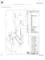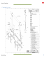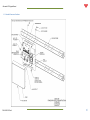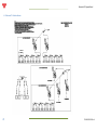
1
Aftermarket LCD Upgrade
Installation Guide
P/N 400-283-301
Revision A
Issue Date 4/27/2009
Aftermarket LCD Upgrade Manual
ii
P/N 400-283-301 Rev A
Aftermarket LCD Upgrade Manual
Aftermarket LCD Upgrade Manual Rev. A
Part Number 400-283-301
Summary of Changes
Change No.
ECR No.
Original
09-0112
List of Effective Pages
Page
All
Change No.
original
Effective Date
6/16/2009
Aftermarket LCD Upgrade Manual
ALL RIGHTS RESERVED
All rights to this installation guide including the diagrams, figures, and technical
specifications are the property of QubicaAMF Bowling Products, Inc. Reproduction
or transmission of any of the material contained in this manual without the prior
written permission of QubicaAMF Bowling Products, Inc. is strictly prohibited. All of
the product information in this guide was carefully prepared based on the latest
information available and was believed to be correct at the time of printing. While
every effort has been made to ensure accuracy, this publication may inadvertently
contain typographical errors, inaccuracies, or errors of omission. QubicaAMF
Bowling Products, Inc. cannot be held responsible for any claims resulting from
these errors.
DOCUMENT UPDATES
QubicaAMF Bowling Products, Inc. reserves the right to revise and/or update this
manual at any time without obligation to notify any person or entity of such revision.
The document number, revision level, and date below indicate the edition of this
manual.
TRADEMARK NOTICES
QubicaAMF and the QubicaAMF logo are the registered trademarks of QubicaAMF
Bowling Products, Inc.
FCC NOTICE
NOTE: This equipment has been tested and found to comply with the limits for a Class A
digital device, pursuant to part 15 of the FCC Rules. These limits are designed to provide
reasonable protection against harmful interference when the equipment is operated in a
commercial environment. This equipment generates, uses, and can radiate radio frequency
energy and, if not installed and used in accordance with the instruction manual, may cause
harmful interference to radio communications. Operation of this equipment in a residential
area is likely to cause harmful interference in which case the user will be required to correct
the interference at his own expense.
Copyright © 2009 QubicaAMF
Document # 400-283-301 Rev. A
Issued: 6/16/2009
QubicaAMF 8100 AMF Drive Mechanicsville, VA. 23111
iv
P/N 400-283-301 Rev A
Aftermarket LCD Upgrade Manual
Table of Contents
1
Introduction ................................................................................................................................. 7
2
Converting Scoring Overhead CRT’s to LCD displays ................................................................... 7
3
Safety Precautions ..................................................................................................................... 10
3.1 Discharging the CRT Tube ................................................................................................. 10
3.2 Preparing Your Work Area ................................................................................................ 11
3.3 Removing Existing CRTs .................................................................................................... 11
3.1 Existing Hanger ................................................................................................................. 12
4
Hanger Assembly and Monitor Hanging .................................................................................... 12
4.1 Assemble Hanger – Single ................................................................................................ 15
4.2 Assemble Hanger – Double ............................................................................................... 16
4.3 Assemble Hanger – Triple ................................................................................................ 17
4.4 Monitor Hanger Parts List - Single .................................................................................... 18
4.5 Monitor Hanger Parts List - Double .................................................................................. 19
4.6 Overhead Monitor Specifications ..................................................................................... 20
4.7 Qubica Enclosure Parts List ............................................................................................... 21
4.8 Assemble Qubica Enclosure .............................................................................................. 22
4.9 Assemble C-90 Enclosure .................................................................................................. 23
4.10 Assemble Boss/XL Enclosure............................................................................................. 24
4.11 Assemble Frameworx Enclosure ....................................................................................... 25
4.12 Enhanced TV Cable Installation ........................................................................................ 26
5
Component Identification .......................................................................................................... 27
5.1 LCI S-Video Interface ......................................................................................................... 27
5.1.1
Ferrite Filter Installation ......................................................................................... 27
5.2 Serial Monitor Control Box ............................................................................................... 28
6
Detailed Wiring Instructions ...................................................................................................... 29
6.1 Power Control Accuscore +/ Qubica ................................................................................. 29
6.2 Power Off with Conqueror ................................................................................................ 30
6.3 Brunswick Frameworx® Enhanced TV............................................................................... 30
Aftermarket LCD Upgrade Manual
7
Making the Right Connections ................................................................................................... 31
7.1 Accuscore Plus No TV / No Drink Light ............................................................................. 32
7.2 AccuScore Plus (C-90) Existing Ads Channel TV ................................................................ 33
7.3 Accuscore Plus (C-90) Enhanced TV and Drink Light ........................................................ 34
7.4 Accuscore Plus (Spectrum) No TV ..................................................................................... 35
7.5 Accuscore Plus (Spectrum) Existing Ads Channel TV ........................................................ 36
7.6 Accuscore Plus (Spectrum) Enhanced TV ......................................................................... 37
7.7 Qubica RGB Enhanced TV ................................................................................................. 38
7.8 Qubica RGB Maintain Existing TV ..................................................................................... 39
7.9 Qubica RGB No TV or Scoring Audio ................................................................................. 40
7.10 Qubica S-Video No Monitor Power Control ..................................................................... 41
7.11 Qubica S-Video No Sound No TV Power ........................................................................... 42
7.12 Brunswick Frameworx®..................................................................................................... 43
8
Power Up & Verify Operation .................................................................................................... 44
8.1 LCD Screen Adjustments ................................................................................................... 44
9
8.1.1
S-Video.................................................................................................................... 44
8.1.2
VGA (RGB) ............................................................................................................... 46
8.1.3
Common Adjustments ............................................................................................ 47
Drink Light .................................................................................................................................. 48
10 Troubleshooting ......................................................................................................................... 49
vi
P/N 400-283-301 Rev A
Aftermarket LCD Upgrade Manual
1 Introduction
Congratulations on your purchase of this QubicaAMF Product. To begin, we will discuss the
layout of this manual. Following this Introduction, the second section discusses what to
expect from your upgrade to LCD displays, and important considerations you need to be
aware of.
The next section, Safety Precautions, contains safety instructions and procedures necessary
for the removal of existing equipment and installation of your new product.
The
symbol is used to draw your attention to a safety precaution. Please pay
special attention to anything following this symbol!
Read and understand all safety instructions and precautions before starting your work!
The next section pertains to assembly and installation of the QubicaAMF monitor support
frame. You will then find sections devoted to detailed instructions for each type of scoring
system supported by the LCI, followed by easy to find diagrams that will help you with
wiring hookups. The final section is where you’ll go once you are ready to power your
system back up. You’ll find steps to take prior to power-up and troubleshooting tips if
something hasn’t gone as expected.
2 Converting Scoring Overhead CRT’s to LCD displays
Replacing scoring CRT monitors with LCD displays provides a significant improvement in
readability and consistency of display. The conversion is simple and immediately improves
the overall look of any scoring system.
LCD monitors are “fixed pixel” displays which can’t suffer from mis-convergence, focus and
color tracking problems so frequently seen in CRT displays. In addition, they don’t rely on
kilovolt power supplies, so they won’t attract dirt to the screen.
There are also things an LCD can’t do. It’s important to be aware of these when
contemplating a conversion.
1) LCD’s can’t increase the resolution of the picture. They can display the existing
resolution in much finer detail and with greater clarity, but a 320x240 picture will
remain a 320x240 picture enlarged to fit the LCD screen. The scoring display won’t
suddenly become High Definition because you installed a new monitor.
2) Bad video with hum, snow, sparkles and jitter will remain bad video with hum, snow,
sparkles and jitter, displayed brighter and clearer than ever. Replacing the display
isn’t going to fix-up the bad video. You have to clean up the interference and noise
and get rid of the hum to realize the full benefits of replacing the monitor.
P/N 400-283-301 Rev A
7
Aftermarket LCD Upgrade Manual
3) Problems you might ignore on the old CRT like a minor flicker in the display will
become quite annoying with the LCD. The barely noticeable twitch becomes a twosecond blink if you don’t clean up the signal.
Putting a new windshield in your car gives you a clearer view but it doesn’t stop the wheel
shimmy or the engine from burning oil. Be prepared to diagnose and repair the problems
that become magnified by the new display.
Some things to check:
Number one on the list is GROUND connections. Connecting the monitor overhead to the
building frame or the electrical conduit isn’t acceptable. It will probably make things worse.
The same goes for the scoring chassis/computer on the curtain wall. Both pieces of the
system, overhead and curtain-wall, must be at the SAME GROUND POTENTIAL! Just running
a protective earth ground to both pieces of equipment doesn’t work, unless they tie
together in the same panel. The display and scoring computer must be physically
connected to the same ground with direct wires from the same ground terminal in the same
panel. Any voltage difference between the overhead ground and the curtain-wall ground
will cause current to flow in the video cabling. This is the number one source of display
problems.
If the two systems are wired from separate panel boxes (or not supplied with the required
isolated ground), run a heavy, #12 AWG minimum wire from the overhead frame directly to
the scoring chassis. Make sure the connection isn’t insulated by paint.
Check the routing of the video cable that runs from the curtain-wall to the overhead. While
these are shielded cables, the shielding is only about 80% effective. Make sure the cables
are routed far away from fluorescent lights, motors and solenoids at the machines and any
other source of electrical noise. When these cables pick up electrical interference, CRT
displays just show some noise in the picture while LCD monitors will probably blink off and
back on.
Check the AC wiring to the overhead assembly. Neutral (the white or blue wire) is NOT THE
SAME as the protective earth ground (the green or green/yellow wire). They are not
interchangeable; they should NEVER CONNECT TOGETHER except at the first power entry
panel. For North American plugs or receptacles, the neutral wire goes to the wide slot or
prong and the protective earth goes to the long, rounded pin. Don’t get them reversed.
Lamps and fans may work but the scoring will have problems.
Older electrical systems often used the conduit or building frame for the protective ground.
This isn’t acceptable for scoring systems. Properly installed scoring power will have a green
(or green/yellow) wire from the isolated ground screw on the outlet that powers the
overhead (you do have IG outlets don’t you?) to the isolated ground bus in the scoring
8
P/N 400-283-301 Rev A
Aftermarket LCD Upgrade Manual
electrical panel. That same ground bus should have another green wire that extends to the
ground connection on the IG outlet on the curtain-wall into which the scoring is plugged.
While this isolated ground stuff may seem irrelevant for utilitarian wiring, it’s very
important for (especially older) scoring systems with remote video displays.
Don’t plug other stuff into the scoring power. Fog machines, extreme lighting and fans or
TVs often introduce currents into the system ground. Keep scoring circuits for scoring only.
P/N 400-283-301 Rev A
9
Aftermarket LCD Upgrade Manual
3 Safety Precautions
3.1 Discharging the CRT Tube
The monitor’s CRT (Cathode Ray Tube) must be discharged. Follow the steps below to
discharge the CRT.
CRT monitors use lethal high-voltage. Use caution when working around these
tubes (especially around ladders).
Read and understand all safety requirements when working on CRT monitors!
Do not work on this product alone. Make certain another capable person is
present to assist in the event of injury.
To avoid electric shock, disconnect the power cord.
CRT’s retain hazardous voltages for long periods of time, even after the power
has been removed. They may also build up a charge while disconnected.
Place one hand behind your back. Placing one hand behind your back helps
prevent current from passing through your heart (if you were to touch a high
voltage area). If you are not comfortable with this procedure, consider contacting
a local TV repair center.
Figure 3 – Discharge Tools
The CRTs must be discharged by connecting a discharge
path between ground and the
anode. To do this, you will need an
insulated screwdriver and wire with
alligator clip(s). Connect the wire to
the shaft of the screwdriver with a
clip (Figure 3, top) or wrap the wire
Figure 1 – Brass Connector
(Figure 3, bottom). Attach the
alligator clip on the other end to
something on the CRT with a good
connection to the black conductive
coating on the rear of the tube (i.e. the brass connector (Figure 1) or the
braided wire (Figure 2)).
Figure 4 – Discharging the
Anode
10
Figure 2 – Braided Wire
Now, slide the flat head end of the screwdriver under the
rubber cap and into the anode opening (Figure 4). You may or
may not hear an electric crackle. The tube has now been
discharged.
P/N 400-283-301 Rev A
Aftermarket LCD Upgrade Manual
3.2 Preparing Your Work Area
You will need the following items:
Scaffolding with wheels (to support 400lbs)
Phillips head screwdriver
Flat blade screwdriver
7/16, 1/2 inch open end wrenches
Wire cutters
Installation instructions
Large piece of cardboard to place both CRT’s
Assemble scaffolding according to manufacturer’s directions. Position the scaffolding
under the overhead to be changed out.
Make certain that the wheels have been locked before attempting to perform any work
on the platform.
Before working on the monitors, make sure the power has been turned off.
Remove both monitor rear covers and place out of working area. Unplug the overhead AC
plug at the side of the incoming power housing. Turn
off the scoring unit.
3.3 Removing Existing CRTs
Unplug all AC power cables to both monitors and the
Monitor control board AC Box. Unplug the video
cables to both monitors and store out of the way for
later use. If present, remove speaker cables and store
for later use.
If you have not discharged the CRT, do so at this time!
Figure 5 - Scaffolding
For safety, position two or more people around the
monitor. Pick up at rear of monitor and remove securing nut from stud while supporting
monitor. Lift front of monitor out of slot in housing.
DO NOT support the monitor using the front bezel (if assembled). The screws can
break off resulting in a dropped monitor!
DO Support monitor from the bottom.
P/N 400-283-301 Rev A
11
Aftermarket LCD Upgrade Manual
Carefully lower the monitor from the scaffold and place front down on a piece of cardboard.
Repeat this step for the other monitor.
3.1 Existing Hanger
Make certain at least two people are available to support the hanger. Open the quick links
on one side and carefully remove the hanger from the chain support. Repeat on the other
side and lower cautiously to the floor, out of the way.
4 Hanger Assembly and Monitor Hanging
If your scoring system uses S-video cabling, it is strongly
recommended you make this connection prior to installing the
hanger bracket to the rear of the monitor.
The correct tool to use for this hardware is an 8MM nut
driver. Use caution when tightening monitor hanger hardware! Overtightening can cause severe damage. Refer to the Hanger Assembly
instructions and the warning on the next page for more information.
12
P/N 400-283-301 Rev A
Aftermarket LCD Upgrade Manual
P/N 400-283-301 Rev A
13
Aftermarket LCD Upgrade Manual
14
P/N 400-283-301 Rev A
Aftermarket LCD Upgrade Manual
4.1 Assemble Hanger – Single
P/N 400-283-301 Rev A
15
Aftermarket LCD Upgrade Manual
4.2 Assemble Hanger – Double
16
P/N 400-283-301 Rev A
Aftermarket LCD Upgrade Manual
4.3 Assemble Hanger – Triple
P/N 400-283-301 Rev A
17
Aftermarket LCD Upgrade Manual
4.4 Monitor Hanger Parts List - Single
18
P/N 400-283-301 Rev A
Aftermarket LCD Upgrade Manual
4.5 Monitor Hanger Parts List - Double
P/N 400-283-301 Rev A
19
Aftermarket LCD Upgrade Manual
4.6 Overhead Monitor Specifications
20
P/N 400-283-301 Rev A
Aftermarket LCD Upgrade Manual
4.7 Qubica Enclosure Parts List
P/N 400-283-301 Rev A
21
Aftermarket LCD Upgrade Manual
4.8 Assemble Qubica Enclosure
22
P/N 400-283-301 Rev A
Aftermarket LCD Upgrade Manual
4.9 Assemble C-90 Enclosure
P/N 400-283-301 Rev A
23
Aftermarket LCD Upgrade Manual
4.10 Assemble Boss/XL Enclosure
24
P/N 400-283-301 Rev A
Aftermarket LCD Upgrade Manual
4.11 Assemble Frameworx Enclosure
P/N 400-283-301 Rev A
25
Aftermarket LCD Upgrade Manual
4.12 Enhanced TV Cable Installation
26
P/N 400-283-301 Rev A
Aftermarket LCD Upgrade Manual
5 Component Identification
5.1 LCI S-Video Interface
Many of the Aftermarket LCD upgrade packages utilize an S-Video interface. If your package
includes this interface, refer to the pictures on this page and also Section 7 – Making the
Right Connections for hookup assistance.
Figure 3 – 283-200-303 Qubica VDB Connections
Figure 4 – 283-200-301 AccuScore Plus Connections
5.1.1 Ferrite Filter Installation
One or two ferrite filter(s) (283-200-209) is/are
Figure 5 – 283-200-302 Frameworx Connections
supplied on systems requiring the S-video interface (Qubica VDB 283200-303 and AccuScore Plus 283-200-301).
For the Qubica VDB system, 2 filters are provided for each of the RGB to
LCI cables (283-200-176). They must be used as shown in the picture at
right. Note that the cable is wrapped around the filter two times.
For the Accuscore Plus system, one filter is provided for use on
the S-Video interface power input cable. Note that the cable is
wrapped around the filter two times.
Please note that no filter is required on the power input cable
for the Qubica VDB S-video interface (283-200-303).
P/N 400-283-301 Rev A
27
Aftermarket LCD Upgrade Manual
5.2 Serial Monitor Control Box
The Serial Monitor Control Box is used in cases where the scoring system provides control of
TV (Ads) function. Connections are made from scoring control to the green terminal strip
(TS) (pictured below center) and to the monitors RS-232 (SERVICE) connection (DB-9).
At right is a portion of drawing 400-283-302-05, showing the
connections to the serial monitor control box. In this configuration,
connections are made with a 4 conductor cable (red, black, green and
white) to the terminal strip connections TS-3 & 4 and TS 7 & 8. In
addition to these connections, there is a DB-9 cable that splits out to
each monitor and attaches to the serial connector of the monitor
(labeled SERVICE).
28
P/N 400-283-301 Rev A
Aftermarket LCD Upgrade Manual
6 Detailed Wiring Instructions
6.1 Power Control Accuscore +/ Qubica
The power plug for the monitor is connected to the power relay cable (283-200-154), which
in turn is connected to the power outlet strip (283-200-019). The power control cable (283200-172) is connected at the S-Video Interface box and the monitor power relay (283-200153).
P/N 400-283-301 Rev A
29
Aftermarket LCD Upgrade Manual
6.2 Power Off with Conqueror
If you have QubicaAMF scoring there is a CD included (400-283-317) that will install files on
your system to enable the LCD’s to power off completely. Insert this CD in your Conqueror
computer and follow the prompts. This process puts an advertising file on your system and
subsequently displays a help file. Follow the instructions in setting up your system to
enable Conqueror to shut down your monitors.
6.3 Brunswick Frameworx® Enhanced TV
In order for Enhanced TV to work with your Brunswick Frameworx® system, you will need to
install a Sync Generator Board (283-200-130) in each lane group processor. Make sure you
isolate this board from any metallic objects or other circuitry (wire ties are provided with all
scoring installation kits).
30
P/N 400-283-301 Rev A
Aftermarket LCD Upgrade Manual
7 Making the Right Connections
Please select the correct diagram for your application. You will use this diagram as it applies
to the options you have purchased to assist you in connecting your LCD properly.
Section Drawing
Number
400-2837.1
302-01
Heading Title
Drawing Description
Page
Accuscore Plus
No TV / No Drink Light
Replace AMF Accuscore Plus overhead with 32” or 42” LCD
monitors using the 283-200-301 LCI. No TV and No Drink
Light
32
7.2
400-283302-02
Accuscore Plus (C-90)
Replace Accuscore Plus (C90) overhead with LCD monitors
Existing Ads Channel TV using the 283-200-301 LCI. Keeps existing Ads (single
channel) TV and drink light
33
7.3
400-283302-03
Accuscore Plus (C-90)
Replace Accuscore Plus (C90) overhead with LCD monitors
Enhanced TV and Drink using the 283-200-301 LCI interface. Provides Enhanced TV
Light
(different channel per lane) and Drink Light
34
7.4
400-283302-04
400-283302-05
Accuscore Plus
(Spectrum) No TV
Accuscore Plus
(Spectrum) Existing Ads
Channel TV
35
7.6
400-283302-06
Accuscore Plus
Replace Accuscore Spectrum overhead with LCD monitors
(Spectrum) Enhanced TV using the 283-200-301 LCI Provides Enhanced TV for a
different channel per lane
37
7.7
400-283304-01
Qubica RGB Enhanced
TV
Replace Qubica RGB overhead monitors with 32” or 42”
LCD using the 283-200-303 LCI. Provides Enhanced TV
allowing a different channel for each lane
38
7.8
400-283304-02
400-283304-03
400-283304-04
Qubica RGB Maintain
Existing TV
Qubica RGB No TV or
Scoring Audio
Qubica S-Video No
Monitor Power Control
Replace Qubica RGB overhead monitors with 32” or 42”
39
LCD using the 283-200-303 LCI. No TV or maintains existing
TV
Replace
Qubica RGB overhead monitors with 32” or 42”
40
LCD using the 293-200-303 LCI. No TV or Scoring Audio
Replace Qubica S-Video overhead monitors with 32” or 42” 41
LCD with or without Enhanced TV. No monitor Power
Control
7.11
400-283304-05
Qubica S-Video No
Sound No TV Power
Control
Replace Qubica S-Video overhead monitors with 32” or 42”
LCD with No Sound or TV Power Control
7.12
400-283318-01
Brunswick Frameworx® Replace Brunswick Frameworx® overhead with 32” or 42”
LCD using 283-200-118 Video Receiver. Enhanced TV
option
7.5
7.9
7.10
P/N 400-283-301 Rev A
Replace Accuscore Spectrum overheads with LCD monitors
using the 283-200-301 LCI No TV
Replace Accuscore Spectrum overheads with LCD monitors
using the 283-200-301 LCI Maintains Ads TV (single
channel) per center
36
42
43
31
Aftermarket LCD Upgrade Manual
7.1 Accuscore Plus No TV / No Drink Light
32
P/N 400-283-301 Rev A
Aftermarket LCD Upgrade Manual
7.2 AccuScore Plus (C-90) Existing Ads Channel TV
P/N 400-283-301 Rev A
33
Aftermarket LCD Upgrade Manual
7.3 Accuscore Plus (C-90) Enhanced TV and Drink Light
34
P/N 400-283-301 Rev A
Aftermarket LCD Upgrade Manual
7.4 Accuscore Plus (Spectrum) No TV
P/N 400-283-301 Rev A
35
Aftermarket LCD Upgrade Manual
7.5 Accuscore Plus (Spectrum) Existing Ads Channel TV
36
P/N 400-283-301 Rev A
Aftermarket LCD Upgrade Manual
7.6 Accuscore Plus (Spectrum) Enhanced TV
P/N 400-283-301 Rev A
37
Aftermarket LCD Upgrade Manual
7.7 Qubica RGB Enhanced TV
38
P/N 400-283-301 Rev A
Aftermarket LCD Upgrade Manual
7.8 Qubica RGB Maintain Existing TV
P/N 400-283-301 Rev A
39
Aftermarket LCD Upgrade Manual
7.9 Qubica RGB No TV or Scoring Audio
40
P/N 400-283-301 Rev A
Aftermarket LCD Upgrade Manual
7.10 Qubica S-Video No Monitor Power Control
P/N 400-283-301 Rev A
41
Aftermarket LCD Upgrade Manual
7.11 Qubica S-Video No Sound No TV Power
42
P/N 400-283-301 Rev A
Aftermarket LCD Upgrade Manual
7.12 Brunswick Frameworx®
P/N 400-283-301 Rev A
43
Aftermarket LCD Upgrade Manual
8 Power Up & Verify Operation
Before applying power, double check all connections. Turn on your scoring chassis, the
breaker on overhead and the power strip. The LCD will display a blue
power light if the LCD has power but has not been turned on. When
powering up, the LCD will display the Qubica logo screen. Once the logo
has turned off, press the <POWER> button on the supplied remote (or on
the front of the monitor). Press the <SOURCE> button on the remote to select the correct
monitor input for your scoring system.
8.1 LCD Screen Adjustments
If your display needs sizing and/or horizontal or vertical adjustment, follow these
instructions. Please note that adjusting the monitor depends on how your monitor
connects to your scoring system. Follow the instructions specific to your setup (S-Video or
RGB).
8.1.1 S-Video
1. Bring a scorer online and make sure your
display shows at least 4 or 5
bowlers in your normal grid
configuration. Go to the Main
Menu by pressing the
<MENU> button on
the remote.
2. Once at the menu above, enter the
numbers <5380> which will bring up this
menu.
3. Scroll down to Setup and press the right
arrow
button.
44
P/N 400-283-301 Rev A
Aftermarket LCD Upgrade Manual
4. Go down to the Panel Size option and press the
right arrow
button.
5. This will bring up the screen at right. Here you
will adjust the horizontal and vertical sizing
using the appropriate control. Please note that
if your scorer connects to the VGA connection
of the monitor, these adjustments will not
affect your display.
6. Once you have adjusted the image for
optimum sizing, return to the second menu by
pressing <MENU> twice, then go to the Video
option.
7. You should now see this screen. Here you will
adjust the centering of the image using the H.
Position and V. Position controls. With an SVideo connection, it may be necessary to go
back and forth between this step and step 5 a
few times to achieve optimal results.
P/N 400-283-301 Rev A
45
Aftermarket LCD Upgrade Manual
8. Once you have satisfactorily setup the
screen for size and centering, go back to the
first menu and enter 9632. If you have
QubicaAMF scoring, you will need to make
sure the option at the bottom of this screen
(Set ID), is set to 1.
9. Once you have completed these
adjustments, go to 8.1.3 Common Adjustments.
8.1.2 VGA (RGB)
1. Make sure your monitor is in VGA mode (Press the
<SOURCE> button and select VGA).
2. Bring the scorer online and make sure your display shows at least 4 or 5 bowlers in
your normal grid configuration. Go to the Main Menu by pressing the <MENU>
button
on the remote.
3. Scroll down to VGA then press the right
arrow
button.
4. This will take you to the screen at right.
The first thing you should do is select Auto
Adjust. This should give you a good
starting point. If further adjustments are
required, use the H. Position, V. Position,
Phase and Clock adjustments.
46
P/N 400-283-301 Rev A
Aftermarket LCD Upgrade Manual
5. If you are experiencing “tearing” on the top of
your screen (in VGA mode) you may need to
adjust the coast start and coast end. Please
follow the directions in section 8.1.1 (steps 1 & 2)
to get to this screen. At the Video option, press
the right
arrow.
Make note of what the values are for both of
these settings as it is possible to over adjust
them which may result in a loss of the display. If
this occurs, reset the values to what they were
prior to any changes. You may need to reset the
display by selecting another input source (select
S-Video then go back to VGA).
8.1.3 Common Adjustments
The screen at right is found when you have selected
the Power Setting option (see picture for S-Video
section 8.1.1 step 8).
Set Power On Mode to Last and Auto Power Off to
Off.
This completes the necessary adjustments for your new monitors and your scoring system.
If any other adjustments are required, please refer to the manual supplied with your
monitors, or call QubicaAMF Technical Support at 866-460-QAMF (7263).
P/N 400-283-301 Rev A
47
Aftermarket LCD Upgrade Manual
9 Drink Light
48
P/N 400-283-301 Rev A
Aftermarket LCD Upgrade Manual
10 Troubleshooting
LCD Issues
Possible Problem
Corrective Action
No picture on LCD
Verify the Power light is
on for all components.
The LCD’s and Monitor
Control Box (if present)
have a power indicator.
Make certain the main
disconnect has been
turned on.
Verify the
power strip has power
and that all items have
been plugged in to the
power strip.
No picture on odd
channel. Error message
“No Signal” or “Not
Supported”
Flexscore CPU must
have the video config set
to 75.
Go to Main Menu of
Flexscore CPU and edit
Video
Config
(19).
Change refresh setting
from 60 to 75.
Save
setting and reboot CPU.
Unable to get a score
grid
LCD is on, but picture
from Accuscore is not
displayed.
Make certain the CWCs
are on.
Correct source has not
been selected.
From the LCD remote,
depress the <SOURCE>
key and select S-Video or
VGA
VGA Display – Top of
screen jittering
Adjustment necessary
Adjust Coast Start/End
Values
Monitor Turns off by itself
Going into Auto Power-off
See section 8.1.3
Common Adjustments
Scorer Grid cutoff or not
centered on screen
Adjustment necessary
See adjustment section
for your monitor hookup.
8.1.1 for S-Video or 8.1.2
for RGB (VGA)
P/N 400-283-301 Rev A
–
49
Aftermarket LCD Upgrade Manual
Hanger Issues
Possible Problem
Gap between LCDs is too Monitors not centered
great.
Monitors appear crooked
50
Hangers brackets
mounted equally
Corrective Action
Move mounting plate on
LCD.
not Adjust hangers
P/N 400-283-301 Rev A