1
;
EefticecUlanual
STEREOTURNTABLE
FL-lcIcI
PL-IcIc|X
(DrrroruEErl"
M O D E LP L - l O OC O M E SI N S E V E NV E R S I O N S
D I S T I N G U I S H EADS F O L L O W S :
Type
Voltage
Remarks
KU
A C 1 2 0 Vo n l y
U.S.A. model (with cartridge)
KUT
A C 1 2 0 Vo n l y
U.S.A. model (without cartridge)
KCT
A C 1 2 0 Vo n l y
C a n a d am o d e l ( w i t h o u t c a r t r i d g e )
WE
AC220V -240V
Europe model (with cartridge)
WB
AC220V -240V
United kingdom model (with cartridgel
WP
AC220V -240V
Oceania model (with cartridge)
R
AC 11O-120I 22O-24OV(switchabt
e)
G e n e r a le x p o r t m o d e l ( w i t h c a r t r i d g e )
o This servicemanualis applicableto the PL-loo/wE, wB, wP, PL-100x/wE,wB.
For servicingof the
other types,pleasereferto the additionalservicemanuat.
A
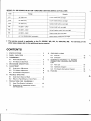
CONTENTS
1. SPEC|F|CAT|ONS.
2.
PANEL FACILITIES
3.
DISASSEMBLY
8.2
Sub-panel
12
15
Paneland BasePlate
4
9 . S C H E M A T I CD I A G R A M .P . C .B O A R D S
3.2
Arm Baseand Sub-Panel
... . .
5
C O N N E C T I O ND I A G R A M A N D P A R T S
LIST
6
9.1
PartsList
16
9.2
S c h e m a t iD
c iagram
17
M E C H A N I S MD E S C R I P T I O N. . .
5.
ADJUSTMENT
5.1
Auto-returnAdjustment
8
5.2
F.G. Motor Adiustment
8
5.3
A r m - e l e v a t i o n A d j u s t m e. .n. t.
8
T R O U B L ES H O O T I N G
6.1
6.2
7.
8 . E X P L O D EV
DI E W S
8.1 Exterior
3.1
4.
6.
3
3
Auto-returnDoesnot Work .
I
(
R
e
t
u
r
n
R e t u r ni s F a s t
a t l m m P i t c h ). . . . . 1 0
PRECAUTIONS
FOR REASSEMBLY
7.1
AreasThat RequireLubrication
10
7.2
Precautionsfor Attachment of Parts
and Reassembly. .
11
9.3 P.C.BoardsConnectionDiagram
1 0 . PACKING
18
19
.l
PL-1 clcl
1. SPECIFICATIONS
Motor and Turntable
Drive System
Motor
Turntable Platter
Speeds.
Speed Control Range.
Wow and Flutter
S i g n a l - t o - N o i s eR a t i o .
Miscellaneous
. Beltdrive
....
Fcservomotor
. 31Omm diam. aluminum alloy diecast
...33-1/3and45rpm
. . x2o/"
. L e s st h a n O . O 4 1 y o( W R M S I
More than 70dB (D|N-B)
( w i t h P i o n e e rc a r t r i d g em o d e l P C - l 3 5 )
Tonearm
Type .
Effective Arm Length
Overhang.
U s a b l eC a r t r i d g e w e i g h t
. Static-balance type, S-shaped pipe arm
.221mm
.15.5mm
. . 4g (min.) to 99 (max.)
WE, WB, WP models
PowerConsumption
Dimensions
Weight
. . . AC Z2O-24OV -, 5O,6OHz
.......
4W
. . . . . 4 2 O ( W ) x 9 6 ( H )x 3 6 b ( D l m m
1 6 - ' tl 2 ( W l x 3 - 1 3 / 1 6 ( H ) x 1 4 - 3 l 8 ( D li n .
5.2kg/11 tb 8 oz
PC-110/l I Specifications
TYPe .
.Moving magnet type
Stylus
. . 0 . 5 m i l d i a m o n d ( P N - 11 0 / t t )
Output Voltage
. 3.5mV (1kHz, 50mm/s Peakvelocity, LAT)
Tracking Force
. . 1.5g to 2.5g (proper 2.2g)
Frequency Response
. 15 to 25,OOOHz
Recommended Load .
. . Soks} +1 70 - 3OOoF
Subfunctions
Accessories
A u t o - r e t u r n m e c h a n i s m ,A n t i - s k a t i n g f o r c e c o n t r o l , S t y l u s p r e s s u r e
d i r e c t - r e a d o u t c o u n t e r w e i g h t , C u e i n g d e v i c e ,S t r o b e l i g h t , F r e e s t o p
E P A d a p t e r
Operating Instructions(French and German
f u r n i s h e d o nm o d e lf o r W E )
hinges
6
Power Bequirements:
Semiconductors
t c . . . .
Transistor
D i o d e .
. .
' . . 1
. ' ' .1
-. . . .
. . . . . ' . . ' . 1
. . . . . . . . . 1
.. . . . .l
NOTE:
Specifications and design subject to possibte modification
notice. due to improvements.
without
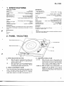
2. PANEL FACILITIES
Platter/R ubber platter mat
Anti-skate knob
S p e e d c h e c k i n gw i n d o w
r^
€) SPEEDSELECTORBUTTON
45 . . . . When this button is depressed,
the platter will
playing
rotate at 45rpm. Depressfor
45rpm
records,singlesor EP's.
position,
33 . . . . When this button is setto the released
platter
rotate
the
will
at 33-1/3rpm. Release
for playing33-1/3rpmrecordslike LP's.
@ SPCEOADJUSTMENTKNOB
Turn this knob when finely adjustingthe speedof the
platter.The speedof platter will increasewhen the knob
is turned to the left in the direction of "+"; it will decreasewhen turned to the right in the directionof "-".
LEVER
@ ARM-ELEVATION
UP (!):
W h e n t h i s l e v e ri s s e t t o t h i s p o s i t i o n ,t h e
tonearmwill rise.Set it to UP beforerecord
play and when you want to stop recordplay
while a track is being played or when you
want to changeoverto a differenttrack.
DOWN (l ): When the lever is set to this position the
tonearm will be lowered. lf it is set to
DOWN for recordplay. the tonearmwill be
lowered onto the surfaceof the record. and
p l a yw i l l b e g i n .
3
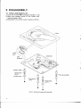
3. DISASSEMBLY
3.1 PANELAND BASEPLATE
1. Undo the 4 screwsO securingthe insulator case,
2. Move the tonearm across to the center. and
raisethe panela little.
3. Disconnect the circuit board connector (2-Pin).
\
Power
ass'y
2-Pin
connector
I
t
Damper
ruuber-f,
Ftoatrpring--p
(BLK)
Insutatorcase-€)
lI -
e
CI
I
o
I
(-=4
---v
F l o a ts p r i n g
(vLT)
,€.
)Y
c-D
uR
I
o
J
U
B-rlort rpring
P (VLT)
G)
fl
o
F i g .3 - 1 Removethe paneland baseplate
4
g-
v/
/€\
)a
(-)
f,
u
I
o
F l o a ts p r i n g( G R E )
PL-1 clcl
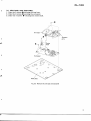
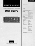
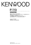
3.2 ARM BASE AND SUB-PANEL
1. Undo the 5 screws O securingthe arm base.
2. Undo the 2 screws O securingthe sub-panel.
3. Undo the 3 screws O securing the center shaft.
Tonearm
ass'y
A
/^O
6"-t----.:
1-."e-".(J\
+--'
@
'
(1'
at.
Fig.3-2 Removethe arm baseand sub-panel
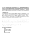
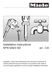
4. MECHANISM DESCRIPTION
PL-1OOMECHANISM OPERATING
The PL-100 is equipped with auto-return only.
Fig. a-t shows the PL-100 in the stationary state
with the tonearm back in the arm rest.
G e a rA
LeverB
Fig. 4-1 Mechanicalpartsname
* Start of Play
1. When the tonearm is moved across to the disc,
the PU plate located below in the arm base is
also moved.
2.Lever A is moved over by pin A connected to
this PU plate, resulting in lever B being unlocked (Fig. -3).
3. At the same time that lever B is unlocked, the
microswitch is turned on (power on), and the
motor commencesto rotate (Fig. -3).
LeverA
P i nA
PU plate
PinB
Fig.4-2 PU plate
Ei
Fig.4-3 Start of play
* AUTO-RETURN DETECTION
l.When the stylus nears the center shaft, pin B
contacts plate A (Fig. A-q.
2. Plate A pushes plate C by an amount direcily
proportional to the amount of movement of
the tonearm (Fig. a-5).
3. Plate D atop plate C is moved toward gear B
by the movement of plate C.
PL-1 Clcl
PinB
s
Fig.4-4 Auto-returndetection1
A
P l a t eD
Plate C
(
Fig.4-5 Auto-returndetection2
4. The front end of plate D moves approximately
0.1mm when the stylus is advanced 1mm
toward the center shaft by one revolution of
the record.
5. The tooth of gear B has the dimensional difference shown in Fig. 4-6.
6. Plate D is pushed back by this dimensional
difference at a stylus movement of within 1mm
per revolution of the record.
7. When the stylus enters the lead-out groove in
the record at the end of the performance, it is
moved 4mm toward the center shaft by one
revolution of the record.
8. The end of plate D contacts the protruding
section of gearB (Fig. -7).
9. Gear B and gear A are engaged, and gear A is
turned by rotation of the turntable.
* AUTO-RETURN
1. Gear A and B are engaged each other by the
auto-return detector and gear A consequently
is turned in the counter-clockwise direction.
2.Plate B is then shifted across towards the tonearm due to the groove in the underneath of gear
A.
3. The edge of plate B pushes against lever C to
force the arm elevation upwards.
4. Plate B continues to shift across to push'against
pin B on the PU plate, thereby returning the
tonearm back to the arm rest.
5. At this stage plate B commences to return toward the center shaft guided by the groove in
gearA.
GearB
f
i
Fig. 4-6 Auto-returndetection3
fGearA
Fig.4€ Auto-return
1
,
Fig.4-7 Auto-returndetection4
6. When the edge of plate B separates from lever
C, the arm elevation is lowered to drop the
tonearm back into the arm rest.
7. And at the same time that the tonearm is
returned to the arm rest, pin A returns lever A
back to the stationary state.
8. Plate B continues to move toward the center
shaft and pushes against pin C on lever B. Lever
B thus switches the microswitch off (power
off), and is then locked by lever A, thereby
bringing a complete operation cycle to an end.
Fig. 4-9 Auto-returndetection2
5. ADJUSTMENT
5.1 AUTO.RETURN ADJUSTMENT
1. Turn the auto return adjustment screw full
around clockwise.
2. Move the tonearm right across toward the
center.
3. When the auto return adjustment screw is
turned back a little at a time counter clockwise,
the tonearm will commence to return to the
outer circumference.
4. Stop tuming the adjustment screw once the
stylus tip is 33mm away from the center shaft.
5. Once the above adjustment procedure has been
completed check that the tonearm returns automatically as designed.
Fig. 5-1 Auto return adjustment
5.2 F.G. MOTOR ADJUSTMENT
1. Twn the power on and start the turntable platter rotating.
2. Turn the speed adjustment knob around to the
mechanically center position.
3. Adjust VR2 and VRB in the motor assembly
so that the stroboscope appears to be stationary.
Again this adjustment is performed from below.
4. Adjust VR2 for 33rpm speed, and VRB for
45rpm.
5.3 ARM-ELEVATION ADJUSTMENT
To proceed with the elevation sheet height
adjustment, insert the hexagonal wrench (for 3
mm) into the hole at the front of the EV sheet and
rotate it clockwise to reduce the height and counter-clockwise to increase the height. The height
of the stylus tip from the record surface is 7
+2 mm.
Fis.5-2 Motor adjustment
Elevation sheet
Fig. 5-3 Armclevationadjustment
PL-1 ctcl
(
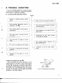
6 . T R O U B L ES H O O T I N G
Use the following directions to find the cause
of each type of breakdown. Improperly adjusted
units should be completely readjusted.
6-1 AUTO.RETURN DOES NOT WORK
START
Change in starting position adjustment.
After starting, incomplete reset of
the plate C. See O
A
The curved section of the plate C
is deformed.
The inner areas of records can not
be tracked.
Arm lead wire is caught on something.
Plate D does not follow the plate C
Too much grease between the plate
C and the gear A.
Inner diameter of the plate D bearing is small.
Protrusions on the caulk
of the plate D bearing.
Not enough grease between
plate D and plate C.
the
PU cord is touching the PU plate.
PU plate is touching the leaf spring
(plate D)
Looseness in the PU plate attachment.
?
Operation of the plate A is not
smooth.
t
Procedurefor Deatingwith ltem O
After performing the return operation, if the
curved section of the plate C and curved section
of the plate D are not in contact with surfaces
@ and @ respectively of the cam, reset will be
incomplete and the starting position will be late.
As a result, the return function may not operate
at times. In this case, bend the plate C (Q so that
dimension A is 0.5mm or larger.
GearA
0.5mm
0.5mm
Fig. 1-6 Incompleteplate D and plateC.
6 . 2 R E T U R Nl S F A S T ( R E T U R NA T l m m P I T C H )
Protrusions on the pinion gear section. See @
Procedurefor Dealing with ltem O
If there are rough areas of plastic protruding
from the @ section of the protruding section of
the pinion gear, the return function may operate
at a pitch of only lmm. In this case, remove the
plastic protrusions completely (Fig. 6-2).
GearB
( p i n i o ng e a r )
protruding
section
F i g .6 - 2 E l i m i n a t i o no f p i n i o n
gearprotrusions.
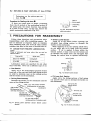
7 . P R E C A U T I O N SF O R R E A S S E M B L Y
Follow these directions and precautions when
reassembling a unit after completing repairs. Be
sure to lubricate as required, make no mistakes
when attaching parts, and avoid all other careless
mistakes that may be the cause of trouble later on.
7.1 AREAS THAT REoUIRE LUBRICATIoN
NOTE:
Types of lubricants
listed in table 1.
and areas where they are used are
Table 1
Type of Oil
Areasused
SiliconOil t60000
raisingshaft
GYA.OOS
all other areas
Lubrication points are specified for oils other
than GYA-008. Never use a different type of oil.
o Cam Section
Apply oil to the heart-shaped grooved section
(rear side of the cam) and lock plate sliding section
in order to minimize wear on the sliding section
and the burden on the mechanism.
o Driving PlateAssembly
Decrease the burden on the mechanism and the
wear on the sliding section.
sides, top, and bottom surfaces
(slidingsectionof auto{top
mechanism)
sidessurface
(slidingsectionof
auto-stopmechanism)
switch locker
openrng
Fig.7-2 Switch lockersection
o EV LeverUnit Section
Apply oil to the sliding sections of leaf spring
(A) and EV lever unit to decreasethe burden on
the mechanism.
l e a fs p r i n g( A )
slidingsection
E V l e v e ru n i t
t o p a n ds i d e
(slidingsectionof
auto{top mechanism)
EV cam side surface
(slidingsectionof elevationcam)
Fig.7-1 Driving panel assembly section Switch Locker
Section
10
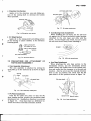
o Switch Locker Section
Apply oil to the switch locker (opening) and
sub-panel base sliding section to decrease the
burden on the mechanism.
When applying oil to the opening (shaft hole),
do not apply any oil 2-3mm from the bottom
surface.
If oil is applied 2-Bmm within the
bottom surface, it may come out the bottom and
go between the switch lever and sub-panel base
causing the switch lever to operate ineffectively.
E V l e v e ru n i t
slidingsection
arm base
Fig. 7-3 EV leverunit section
PL-1 clcl
(
o Elevation Cam Section
Apply oil to the elevation cam and sliding section of the raising shaft to decreasethe burden
when operated.
Fig. 7-7 PU plateattachment
Fig. 7 -4 Elevationcam section
a
r EV SheetSection
Apply oil to the raisingshaft and'slidingsection
of the bearing to assurestability in the elevation
loweringspeed.
o Anti-Skating Knob Attachment
When installing the AS knob, put the AS knob
rib against the AS knob revolution control stopper
(attached to the arm base) and affix with the
screw. As the stopper may break, be sure to press
the AS knob down firmly when installing it.
apply allaround
at a width of 1mm
half of the grooved
EV sheetassembly
Fig. 7-5 EV sheetsection
7.2 PRECAUTIONSFOR ATTACHMENT OF
PARTSAND REASSEMBLY
f
o GamAssemblyAttachment
The cam assemblyis attached by letting the
lock plate go in the direction @ as shown in figure
1-6.
driving
a
Fig. 7-8 AS knob attachment
o Arm BaseAttachment
When attaching the arm base section to the
mechanism section, put the mechanism section
switch locker and switch lever in the locked posi
tion and verify that the tonearm is in the arm rest
location. Also be sure to put the manual elevation
lever in the up position and check that the PU
plate shaft is in the position shown in figure 7-9.
Fig. 7-6 Camassemblyattachnent
a
o PU Plate Attachment
Push the PU plate into place so that the PU
plate bearing section touches the revolution shaft
attachment nut. Installation direction is as shown
in figure 7-7. Note that there is a difference between auto-retum and fully automatic models.
Switch lever Switch locker
F i g . 7-9 Arm baseattachment
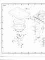
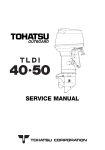
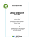
8 . E X P L O D E DV I E W S
8.1 EXTERIOR
NOTE:
c Parts without part number cannot be supplied.
o The A marh found on some component parts indicates the importance of the
safety factor of the part. Therefore, when replacing, be sure to use parts of identical designation.
Partslist
Key No.
1.
2.
3.
4.
5.
6.
7.
8.
9.
10.
Part No.
Description
Lens holder
Lens
46.
47.
48.
49.
50.
PDE-044
PNV-034
PXB-155
PNX-062
PBH-264
PU cord
Dust cover
Hingeassembly
Foot case
Foot spring (A)
Mirror
Push button
Knob
Base plate
S u b - p a n e la s s e m b l y
51.
52.
53.
54.
55.
PBH-265
PEB-163
PBA-099
PXA-841
Foot spring (Bl
Rubber cushion
Screw
Weight assembly
Button guide C
Part No.
Description
PNX-151
PAM-O68
PAM-O69
Panel
Name plate
Name plate
PNX-051
PAC-043
PAC-047
Key No.
l
I
11.
12.
13.
14.
15.
PNR-l40
KEB-004
PEB-150
PYY-071
Turntable platter
Belt
Rubber mat
Motor assembly
Motor pulley
56.
57.
58.
59.
60.
16.
17.
18.
19.
20.
PEB-172
P B A -1 2
PBA-108
PBA-109
PPD-603
Rubber cushion
Screw
Screw M3x25
Screw
Arm assembly
61.
62.
63.
64.
65.
PNX-O74
21.
22.
23.
24.
25.
PXA-792
PBA-9o5
PNX-152
PAC-045
PNX-054
Headshell assembly
Screw
Arm base
AS knob
AS washer
66.
67.
68.
69.
70.
PM230P050FMC
PPZ30P080FMC
PLZ40P120FMC
PDZ30P050FMC
26.
27.
28.
29.
30.
PNX-055
PBH-236
PBE-O1
2
PBF-005
PX8-094
Base lever
AS spring
AS spring washer
AS knob washer
Arm rest assembly
71.
72.
73.
74.
75.
P D Z 3 0 P 0 8 0 F M C Screw
ZMR30H120FZK
Screw
Screw
ZMD40H080BT
VBZ30P080FMC
Terminal
Screw
3 1.
32.
33.
34.
35.
PXB-107
PBH-237
PXT-382
PNX-059
PBH-238
EV
EV
EV
EV
EV
76.
77.
78.
79.
80.
rPZ30P100FMC
YE30S
YE70S
PXT-910
PBH-266
Screw
E type washer
E type washer
Cartridge(without stylus)
Foot spring (C)
36.
37.
38.
39.
40.
PBK-042
PXT413
RNX-060
EV plate spring {A}
E V p l a t e s p r i n g( B ) u n i t
PU plate (A)
Set screw
PU plate (B)
41.
Aqz
43.
A ++.
45.
PNX-061
sheetassembly
spring
l e v e ru n i t
cam
cam spring
prr-l07
PU plate spring
Power transformer
PDG-021
RDG.O22
PDG.O2O
PEC-056
Connector assembly
AC power cord (WE)
AC power cord (WB)
AC power cord (WP)
Strain relief
PBH-259
PSG-020
PBH-261
PCS-016
PEL-O42
PXB-177
PNC-132
VBZ30P100FMC
Angle
Push switch
Spring
Variable resistor
Neon lamp
Neon lamp base
Power supply assembly
Shaft assembly
Plate
Screw
Screw
Screw
Screw
Screw
Cord clamper
PL-1OOX
Key No.
1.
2.
3.
20.
21.
23.
24.
Part No.
Description
P N X -5
15
PAM-070
PAM-071
PPD-609
PXA-791
PNX-156
PAC-041
Panel
Name plate
Name plate
Arm assembly
Head shell assembly
Arm base
AS knob
i
(
\.a
0-
.NY.
t
56
I
66-€'-
q,
i,
L
PL-1 clcl
-j *l
Y'" a''
a4-=,
l\ I
-lK
I
V I
f.-+-
-74
i6{ y)l
T\ ir?7/
l3317
?
':_la
75..- --{-iii
64 g-ue
+
-*]\
6?
cl-.'t
l
z
li9-az
&
k$.o
\
d--
e"9
ce"
.7oA
g-un
77
'q
'
@
o
H
t l
53----+l
5
-25
-75
s
ll*"
t l
-28
26
Y
PL-1 clc'
8.2 SUB-PANEL
F,"
rt
(
'u,
t.-.-.#
ffi
f
i'
Partslist
Key No.
Part No.
Description
YE40S
PNX-030
PNX-031
PXT-355
S u b - p a n e lu n i t
E type washer
Switch lever
Plate
Lever unit
l
2.
3.
4.
5.
6.
7.
8.
9.
10.
Operation lever assembly
Start plate
Start plate spring
EV cam
P M K 2 6 P l O O F M C Screw
PNC-1
26
PBH-224
Key No.
Part No.
Description
11.
12.
13.
14.
15.
PNX-035
PBH-225
PNX-O36
PYY-058
PSF-Oog
Lock plate
Lock plate spring
Cam
R e t u r n s i g n a lu n i t
Microswitch
16.
17.
18.
PDE-079
PBA-103
YE155
Connector assembly
Screw
E type washer
CONNECTION
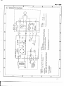
9. SCHEMATICDIAGRAM,P.C.BOARDS
DIAGRAM AND PARTS LIST
NOTE:
When ordering resistors,first conuert resistance values into code form as shown in
the following example*
Ex. I When there are 2 effectiue digits (any digit apart from 0), such as 560 ohm
and 47k ohm (tolerance is shown by J = SVo,and K = 10Vo).
RDVlPStrG]m.f
...
56Oa-56xl0t-561
473
. . . RD%PS aaa J
47 x1O34?hagSa_ORS
... RN2HEl861(
...
... RS/P@m@K
...
Ia-010
o
When there are'3 effectiue digits (such as in high precision metal film
resisfors/.
. . RN%SR tr@Dtr r'
5621 . .
562 x 10t
5.62ha
parts
indicates the importance of the
o The A mark found on some component
safety factor of the part. Therefore, when replacing, be sure to use parts of
identical designation.
Ex.2
9.1 PARTS LIST
PowerSupplyAssembly
Motor Assembly(PYY-071)
Part No.
Symbol & Dccription
Part No.
2SC1959-Y
01
PCX-O1o
wz-120
D1
D2
c E A 1 0 2 M2 5 L
CKDYF 1032 50
C2
C3
A pcl-oss
2SD947
EVN.31AAOOB24
ERD-78TJ103
ERO-25CKF2002
ERO-2sCKF6201
cs
R S 2 P F3 6 T J
B D % P S1 5 2 J
R S 2 H S F B3 3 3 J L
R1
R2
R4
PCS-016
VRl
PSG-020
A.pet-o+z
PBH.261
A per-osg
Volume
Push switch
Neon lamp
Push button spring
Fuse
lCs
of Transistors
Appearance
2SC1959
Type No
16
25D947
Symbol & Description
01
V R 2 ,V B 3
R1
R2
B3
-
PL-1 clct
9 . 2 S C H E M A T I CD I A G R A M
-
C
-
:
-!
oo
l
o
H 3 l oz
- ' n l
| \ l
E
z
nl
o n l
::
E
!
;
t.
l o
r<
o.(J
< ro_
( t sI , C
o r o
F I F
O r O
do
;
[_
r H
n 6
- o
I K
3
!?=il
6 a o
b
5
Boi,j
tr
=
a
o <
ruoi
E u
o o
E U
I
>ou<
>:=
: ;
I
'
I
I
i
>
€ *
g,9
L -
b
E
- d
o
i
;
=
I
P E
z
c
'=
@
=
oi'
6
:
o
G
e
O
:
<
O
5 F c
3
! €o
o x
g
t
!;
c
a
:
o
o
_
*
O
E
9 :v !;
F
o
. 9 i t
- E c
- @
6 € *
o . i
@
€
- .l o 5
-$l
H;
o o
;
E E ,
9 ; :
l i t
X N
di;
t s !
E . s
P c t i o
Y 9
R;i){E
?.P
? E € ; ES
g 4
, ^ 4 ' E ;I
E ! - < :-l *F
-gl
+ 1
o
z l
O J
U U
z t
9
5
< l
n.E
oe
i
6sfEI =:
-(Dx
= O
(,0_
<<1
\
j
t
o
L i
- ,
..
r
;9F
c
O : Y
n
:;i
>6
u;
i
Y
c
o
q ;
. 4 - .
; 9
E F
E ;
o E
5 b
0 6
i 9
o o
8 v
i;
I
;ts
e rl :
E :Z
5 X
:>
I
sN
t -
a+'
+ -
I
F
I
c . 9
o
:
=
^
F
@
_-9
P
o
F,a
€
*
ii6'
J
O
F -
i.u
E
=-HE;
x : E . i : i 5 d s c a)
;c i = :L B
O.:
,,io
9 p I
L p E
E = 2
d
c ) : :
r
U ? 9
9
E" g ?
EE fln;
4 9
< 9 P
o l j n
> ' ( t
t
1 7
-
PL-1 clct
9 . 2 S C H E M A T I CD I A G R A M
-
C
-
:
-!
oo
l
o
H 3 l oz
- ' n l
| \ l
E
z
nl
o n l
::
E
!
;
t.
l o
r<
o.(J
< ro_
( t sI , C
o r o
F I F
O r O
do
;
[_
r H
n 6
- o
I K
3
!?=il
6 a o
b
5
Boi,j
tr
=
a
o <
ruoi
E u
o o
E U
I
>ou<
>:=
: ;
I
'
I
I
i
>
€ *
g,9
L -
b
E
- d
o
i
;
=
I
P E
z
c
'=
@
=
oi'
6
:
o
G
e
O
:
<
O
5 F c
3
! €o
o x
g
t
!;
c
a
:
o
o
_
*
O
E
9 :v !;
F
o
. 9 i t
- E c
- @
6 € *
o . i
@
€
- .l o 5
-$l
H;
o o
;
E E ,
9 ; :
l i t
X N
di;
t s !
E . s
P c t i o
Y 9
R;i){E
?.P
? E € ; ES
g 4
, ^ 4 ' E ;I
E ! - < :-l *F
-gl
+ 1
o
z l
O J
U U
z t
9
5
< l
n.E
oe
i
6sfEI =:
-(Dx
= O
(,0_
<<1
\
j
t
o
L i
- ,
..
r
;9F
c
O : Y
n
:;i
>6
u;
i
Y
c
o
q ;
. 4 - .
; 9
E F
E ;
o E
5 b
0 6
i 9
o o
8 v
i;
I
;ts
e rl :
E :Z
5 X
:>
I
sN
t -
a+'
+ -
I
F
I
c . 9
o
:
=
^
F
@
_-9
P
o
F,a
€
*
ii6'
J
O
F -
i.u
E
=-HE;
x : E . i : i 5 d s c a)
;c i = :L B
O.:
,,io
9 p I
L p E
E = 2
d
c ) : :
r
U ? 9
9
E" g ?
EE fln;
4 9
< 9 P
o l j n
> ' ( t
t
1 7
f-
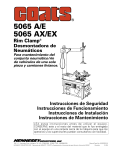
9.3 P.C. BOARDS CONNECTIONDIAGRAM
MOTORAtr'y
MOTORP.C.B.As'y
PgryE_lMlsFof,r\4ER
I RED
I
I
AC 220-240V
50/60Hz
i RED
22o-24ov i
s1
POWER
RED BRN
POWERSUPPLYAsc'y
L _ _ _ _ _ _ _ _ _ _ _ J
I
I
PL-1 clcl
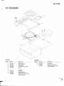
1 O .P A C K I N G
s
d
\
fVr
cd
Partslist
Key No.
1.
2.
3.
4.
5.
6.
7.
L
9.
PL.lOOX
Part No.
Description
PHA-107
PHA-108
PHG-414
PNX-O64
PBA-100
Side protector L
Side protector R
P a c k i n gc a s e
Turntable platter packing
Key No.
3.
9.
Part No.
Description
PHG416
PRB-167
PRD.O55
Packing case
Operating instructions
Operating instructions (WE)
(French/German)
Screw
Viny bag
N93-603
PXA-841
PRB-162
PRD.O54
45 adaptor
Weight assembly
Operati ng i nstructions
Operating instructions (WE)
(French/Germanl
--It
1ql
I
,
I
ll
t
iI
a
iI
l
ll
i
FICINEEFI
t .l. FEIf{IEFI
F|C'NICF|
FfCIfVIEFI
(aRT-s13€)
4-l , Mesuno 1-chome, Mesuno-ku, Tokyo 1s3, Japan
ELECTFICINIC
CCIFIPCIFIATICIN
ELECTFIC'NICE CCIFIFCIF|ATICIN BS Oxfond Onive, Moonechie, New Jeesey O7O74, U.S.A.
|lLlCTFlCtNlC
ILEC?FlCtNlClt
(EUFIC'FE'
A|JITFALIA
N.\/.
Luithegen-Haven
17A-1A4
FTY.
LtE,.
9. PO3O
Antwenp,
Elound6.v
F|oBd,
Belgium
Bnae6ide,
VicEonia
3195,
Aust.alia
FiC)MAF.19BO
P.intsd
in JePEn