1
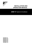
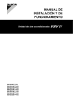
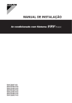
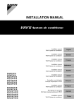
16 Operation 16.3.3 To use the dry program (WITH cool/heat changeover remote control switch) ▪ The air flow flap itself adjusts its position. ▪ The air flow direction can be fixed by the user. To start 1 The air flow direction can be adjusted in one of the following ways: Select cooling operation mode with the cool/heat changeover remote control switch. ▪ Automatic and desired position . WARNING Never touch the air outlet or the horizontal blades while the swing flap is in operation. Fingers may become caught or the unit may break down. 1 NOTICE 1 2 3 4 ▪ The movable limit of the flap is changeable. Contact your dealer for details. (only for doubleflow, multiflow, corner, ceilingsuspended and wallmounted). Press the operation mode selector button on the user interface several times and select (program dry operation). . It may ▪ Avoid operating in the horizontal direction cause dew or dust to settle on the ceiling or flap. Press the ON/OFF button of the user interface. Result: The operation lamp lights up and the system starts operating. 16.5 Setting the master user interface Press the air flow direction adjust button (only for doubleflow, multiflow, corner, ceilingsuspended and wallmounted). Refer to "16.4 Adjusting the air flow direction" on page 84 for details. 16.5.1 About setting the master user interface a To stop 5 Press the ON/OFF button on the user interface once again. Result: The operation lamp goes out and the system stops operating. b c b d NOTICE Do not turn off power immediately after the unit stops, but wait for at least 5 minutes. 16.4 Adjusting the air flow direction Refer to the operation manual of the user interface. 16.4.1 About the air flow flap Double flow+multiflow units Corner units e e a b c d e f d f f VRV heat pump outdoor unit VRV direct expansion (DX) indoor unit BP box (required to connect Residential Air (RA) or Sky Air (SA) Direct Expansion (DX) indoor units) Residential Air (RA) Direct Expansion (DX) indoor units) User interface (dedicated depending on indoor unit type) User interface (wireless, dedicated depending on indoor unit type) When the system is installed as shown in the figure above, it is necessary to designate one of the user interfaces as the master user interface. Ceiling suspended units The displays of slave user interfaces show (changeover under centralised control) and slave user interfaces automatically follow the operation mode directed by the master user interface. Wallmounted units Only the master user interface can select heating or cooling mode. Indoor unit master allocation is determined as follows in special cases: For the following conditions, a micro computer controls the air flow direction which may be different from the display. Cooling Heating ▪ When the room temperature is ▪ When starting operation. lower than the set ▪ When the room temperature is temperature. higher than the set temperature. ▪ At defrost operation. ▪ When operating continuously at horizontal air flow direction. ▪ When continuous operation with downward air flow is performed at the time of cooling with a ceilingsuspended or a wallmounted unit, the micro computer may control the flow direction, and then the user interface indication will also change. Installer and user reference guide 84 Case Description VRV DX indoor unit combined with Hydrobox unit The operation mode is always forced by the master user interface of the VRV DX indoor unit. The Hydrobox unit cannot select the operation mode (cooling/ heating). VRV DX indoor units combined with RA DX indoor units The operation mode is by default selected by the master user interface of the RA DX indoor unit. Contact your installer if you wish to know which indoor unit type received the master allocation. RYYQ+RYMQ+RXYQ8~20T7Y1B VRV IV system air conditioner 4P3704751 – 2014.02