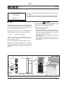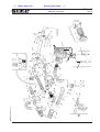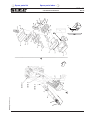
1
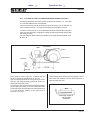
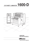
AUTOMATIC
LAMINATOR
1600-SPC
Morton Electronic Materials
Index
Notice
Warranty
Description of the symbols
Special recommendations for the operator
OPERATING
AND SERVICE MANUAL
Ed. 05/01
Home page
EXIT
Cover
Index
Index
Cover
1600-SPC
NOTICE
THIS INSTRUCTION MANUAL SHOULD BE READ CAREFULLY BEFORE
INSTALLING, OPERATING OR PERFORMING MAINTENANCE ON THE
MACHINE.
THE INFORMATION CONTAINED HEREIN IS CORRECT ACCORDING TO
OUR KNOWLEDGE. MORTON, HOWEVER, IS NOT RESPONSIBLE FOR
EVENTUAL INACCURACIES HERE DESCRIBED.
THE USER IS RESPONSIBLE FOR THE SAFE INSTALLATION AND
OPERATION OF THE MACHINE.
Ed. 05/01
Index
Cover
1600-SPC
WARRANTY
The machine is guaranteed by Shipley against defects in materials and
workmanship for a period of 90 days from the date of receipt by the customer.
During this time Shipley will be responsible for the replacement or repair, at its
option, of any defective parts and for any labor charges connected with the
repair of the machine.
For an additional period of 90 days, Shipley warrants that it will replace or repair
any parts recognized as being defective at its discretion. All labor charges will,
however, be at the customer’s charge during this additional 90 days period.
Shipley should be notified in writing of any defects in materials or workmanship
and, if such instructions are given, the machine or any part thereof may be
shipped to Shipley for repair.
Neither the machine nor any part thereof should be returned to Shipley without
written authorization from the same.
This warranty is only effective when the machine is installed in accordance with
Morton’s specifications.
The warranty becomes void if the machine is incorrectly used or contrary to the
instructions, or if alterations or repairs are made by un authorized Shipley
representatives or without written permission from Shipley.
Shipley will merely be responsible for repairing and/or replacing defective parts
and for repairing failures without any charge for the purchaser and in compliance
with the above mentioned conditions.
Shipley is not responsible for any incidental or consequential damages.
Morton’s liability will never exceed reimbursement of the purchase price of the
machine.
This warranty is expressly in lieu of all other explicit or implicit guarantees
including the warranty of marketability or fitness for a particular purpose.
Shipley is a registered trademark.
Ed. 05/01
Cover
Index
1600-SPC
SPECIAL RECOMMENDATIONS FOR THE OPERATOR
- The terms: right, left, upper, lower, etc. used in this
manual to describe and locate the machine
components and parts always refer to the correct
position of the operator when inserting the panels
during standard operation.
- Before starting to work on the machine, the operator
must be completely familiar with this manual, the
technical specifications of the machine and its
controls.
- It is also advisable for the operator to attend a
training period on how to use the machine.
- The mechanical parts and the electric components
are located inside the machine and are protected
by panels entirely closed by screws plus safety
microswitches or interlocked switches.
- Before removing the safety protections to have
access to the internal parts, make sure that the
main power switch of the machine is in “OFF”
O position, so that there is no power into the
machine when the operator works.
- During the installation, it is essential to provide a
building line main switch and a ground system fully
complying with industrial accident prevention
regulations.
- Any control or periodic maintenance operations
which require the removal of safety protections
are to be intended as effected under the full
responsibility of the User and therefore should be
carried out only by authorized and skilled persons.
- Shipley will not be responsible for accidents or
damages to persons or things, when such
fundamental safety rules are not complied with.
Ed. 05/01
- Anyway such rules, together with all rules
concerned with the installation of the machine
and with electrical connections, are an integral
part of the industrial accident prevention
regulations of any single Country.
- Never carry out improvised or hurried repairs
which might compromise good machine
operation.
- SHOULD ANY DOUBT ARAISE ALWAYS ASK
SKILLED MORTON PERSONNEL FOR
INTERVENTION.
- Periodically check the efficiency of the safety
devices and protections and make sure that
they are operating.
- ANY ERRONEOUS INTERVENTION BY THE
USER WILL IMPLY NO LIABILITY WHATSOEVER ON MORTON, AND THE USER SHALL
BE FULLY LIABLE TOWARDS THE
COMPETENT AUTHORITIES FOR ACCIDENT
PREVENTION.
Index
Cover
1600-SPC
DESCRIPTION OF THE SYMBOLS
Many accidents are caused by insufficient knowlegde of the safety regulations
or failure to apply these instructions when running or servicing a machine.
To prevent accidents, it is essential to read, understand and comply with all
the precautions and warnings contained in this manual and those reported on
the safety plates fixed to the machine.
The following symbols have been used to identify the safety messages printed
in this manual:
DANGER
This symbol is used to identify safety messages when these draw the
operator’s attention to situations of danger.
WARNING
This symbol is used to identify safety messages when these draw the
operator’s attention to situations of danger which, if ignored, could
cause slight or moderate injuries or damages.
The message can be also used for dangers which can cause damages
to the machine.
NOTE
This symbol is used to identify precautions the operator must take in
order to avoid operations that could reduce the life of the machine, or
to identify important information for the operator.
IMPORTANT
For clear information some of the illustrations in the manual
show the machine without safety guards.
NEVER USE THE MACHINE WITHOUT SAFETY GUARDS.
Ed. 05/01
Cover
1600-SPC
Index 2 of 2
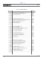
GENERAL INDEX (1/2)
INTRODUCTION
1.1
1.2
1.3
1.4
1.5
1.6
TECHNICAL FEATURES .........................................................
GENERAL DESCRIPTION ......................................................
LAYOUT ...................................................................................
ELECTRICAL CONTROL CABINET ........................................
MACHINE IDENTIFICATION ...................................................
1.5.A Check at reception. ........................................................
PRELIMINARY CHECKS AND INSTALLATION ......................
1.6.A - Installation ....................................................................
1.6.B - Machine positioning and leveling .................................
1.6.C - Pneumatic connection ..................................................
1.6.D - Connection of the exhaust hose ...................................
1.6.E - Electrical connection ....................................................
1.6.F - Check of the electrical connection ...............................
1.6.G - Electrical connection in line with other machines .........
I
I
I
I
I
I
I
I
I
I
I
I
I
I
- 1
- 3
- 5
- 5
- 6
- 6
- 6
- 6
- 7
- 8
- 8
- 9
- 9
- 10
OPERATIONS
2.1
2.2
2.3
2.4
CONTROL PANEL ON THE CABINET ...................................
CONTROL PANEL ...................................................................
PUSH-BUTTON PANELS ON THE MACHINE ........................
PNEUMATIC ADJUSTMENT CONTROL PANEL ...................
II
II
II
II
-
3.1
3.2
3.3
3.4
OPERATOR GUIDE FOR START UP .....................................
OPERATING CYCLE ...............................................................
OPERATIONS OF THE VARIOUS GROUPS/ INDEX ............
ADVICE FOR LAMINATION ....................................................
3.4.1 Temperature of the input panel ......................................
3.4.2 Temperature of the rubber pads for tacking ..................
3.4.3 Tacking time ..................................................................
3.4.4 Lamination pressure ......................................................
3.4.5 Temperature of the lamination rolls ...............................
3.4.6 Static tension on the dry film coils .................................
3.4.7 Distance between input panels ......................................
SETTING UP THE UNIT ..........................................................
II
II
II
II
II
II
II
II
II
II
II
II
- C.1
- D.1
- E.1
- G.1
- G.1
- G.1
- G.1
- G.1
- G.2
- G.3
- G.3
- H.1
INPUTS/OUTPUTS LIST .........................................................
4.1.A PLC digital input list .....................................................
4.1.B PLC digital output list ...................................................
4.1.C PLC analogue input list ...............................................
4.1.D PLC analogue output list .............................................
II
II
II
II
II
-
3.5
4.1
A.1
A.2
B.1
B.2
I.1
I.1
I.2
I.3
I.3
➥➥➥
Ed. 05/01
Manual realized by DUESSE design for Shipley
Duesse - Samarate (VA) - Tel. 0331 / 23.59.34 - www.duesse.it
LI 1600-SPC - 99-2095
Cover
1600-SPC
Index 1 of 2
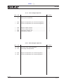
GENERAL INDEX (2/2)
5.1
5.2
----
COMPLETE LIST OF ALARM MESSAGES
AND IDENTIFICATION CODES ..............................................
DESCRIPTION OF ALARM MESSAGES
ON ALLEN BRADLEY DISPLAY .............................................
BATTERY REPLACEMENT FOR PLC ALLEN BRADLEY ......
REPLACEMENT OF THE FLASH ATA CARD
CONTAINING THE MESSAGES .............................................
FLOW CHART OF ALLEN BRADLEY PV 900 DISPLAY ........
II - L.1
II - M.1
II - N.1
II - N.2
II - N.3
MAINTENANCE
6.1
-----
CHECK AND MAINTENANCE TABLE ....................................
CHECKS AND MAINTENANCE ..............................................
6.1.A - General information ......................................................
6.1.B - Routine maintenance ...................................................
6.1.C - Extraordinary maintenance ..........................................
6.1.C.1 Replacement of the lamination rolls .................
6.1.C.2 Replacement of the IR lamps ...........................
6.1.C.3 Replacement of the tacking bars......................
6.1.C.4 Replacement of the movable blades ................
6.1.C.5 Replacement of the counterblades ..................
PACKING AND SHIPPING ......................................................
LIFTING THE CRATE ..............................................................
LIFTING THE MACHINE .........................................................
DEMOLISHING THE MACHINE ..............................................
III
III
III
III
III
III
III
III
III
III
III
III
III
III
-
1
2
2
2
2
3
4
5
7
7
a
a
b
b
SPARE PARTS
-
ORDERS
INDEX
DRAWINGS
NUMERICAL INDEX
ELECTRIC DRAWINGS
OPTIONS
---
THIN PANEL UNIT ........................................................... Options I - I.1
EXPANSION ROLLS ...................................................... Options II - II.1
Ed. 05/01
Index
1600-SPC
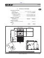
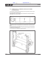
1.1
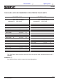
TECHNICAL FEATURES
1/2
ELECTRICAL FEATURES
• Power type ............................................. three-phase 50/60 Hz + ground
• Power consumption .................................................................... 8.5 KVA
• Nominal voltage .................................................. 380/415/480/220/200 V
• Building line main switch
- for 380-415 V tensions ............................ I= 20A “motor starting” type
- for 480 V tension ..................................... I= 16A “motor starting” type
- for 220-200 V tensions ............................ I= 25A “motor starting” type
PNEUMATIC FEATURES
• Consumption ................................................. 12 NI/cycle ... 1 CFM/cycle
2
• Operating pressure .......................................... 6 kg/cm . ......... 85 PSIG
EXHAUST FEATURES
• Max. air consumption for exhaust .............................................. 300 m3/h
WEIGHT
• Gross ................................................................. 1750 kg ........... 3860 lb
• Net ..................................................................... 1402 kg ........... 3090 lb
600 mm
23.62”
110 mm
4.33”
850÷1050 mm
33.00”÷42.00”
600 mm
23.62”
1000 mm
39.37”
1680÷1880 mm / 66.00”÷74.00”
300 mm / 11.8”
1760 mm / 69.00”
1730 mm / 68.00”
Note: Allow 1000 mm (39.37”) on each side where the operator must work
Ed. 05/01
OVERALL DIMENSIONS
I- 1I-1
Index
1600-SPC
1.1
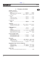
TECHNICAL FEATURES
2/2
GENERAL FEATURES
➨ Max overall dimensions
• Width ............................................................... 1730 mm ............... 68.00”
• Max length (with roller extended) .................... 1760 mm ............... 69.00”
• Height (min÷max) ............................... 1680 ÷ 1880 mm ... 66.00”÷74.00”
➨ Input roller
• Width ................................................................. 900 mm ............... 35.43”
• Length (fixed roller) ........................................... 600 mm ............... 23.62”
• Length (folding roller) ........................................ 300 mm ............... 11.81”
➨ Output roller
• Width ................................................................. 900 mm ............... 35.43”
• Length ............................................................... 250 mm ................. 9.84”
CONVEYOR
• Conveyor height (min÷max) .................. 850 ÷ 1050 mm ... 33.00”÷42.00”
• Adjustable conveyor speed ..................... up to 5 m/min. ........... 16,5 fpm
LAMINATION ROLLS
• Diameter ........................................................... 100 mm ................. 3.93”
• Length ............................................................... 814 mm ............... 32.00”
• Hardness .................................................................................. 60 Shore
• Lamination speed (min÷max) ................. 0.5 ÷ 5 m/min. 1,65 ÷ 16,5 fpm
• Rolls temperature (min÷max) ........................................... Room ÷130°C
• Rolls pressure (max. at 6 bar) ............................ 320 kg ............... 704 lb
FRONT AND REAR EDGES
• Both adjustable (min÷max) ........................... 0 ÷ 50 mm ........... 0”÷ 1.96”
• Front edge tolerance (max) ............................ ± 0.5 mm ............... 0.019”
• Rear edge tolerance (max) ............................. ± 1.0 mm ............... 0.039”
PANEL SIZE
• Width (min÷max) ..................................... 120 ÷ 787 mm .... 4.70”÷ 31.00”
• Length (min÷max) ................................... 210 ÷ 787 mm .... 8.26”÷ 31.00”
• Thickness (min÷max) ................................... 0.1 ÷ 5 mm .. 0.004”÷ 0.196”
(with optional thin panel unit) (min) ........... 0.05 mm ............. 0.0019”
DIMENSIONS OF DRY FILM FOR LAMINATION
• Width (min÷max) ..................................... 120 ÷ 762 mm .... 4.72”÷ 30.00”
• Length (min÷max) ................................... 187 ÷ 762 mm .... 7.36”÷ 30.00”
• Coil diameter (max) .......................................... 240 mm ................. 9.50”
• Thickness ..........................................................................all thicknesses
NOISE LEVEL
• Max (continuous pondered equivalent value “A”) ............................75 dB
Ed. 05/01
I- 2
Index
1600-SPC
1.2 GENERAL DESCRIPTION
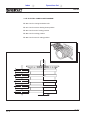
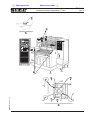
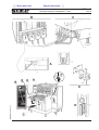
(picture 1 - page I-4)
- The Shipley Laminator mod. 1600-SPC is a
completely automatic 30" laminator, based on a
totally new design concept, constructed to
guarantee the highest lamination quality and
absolute reliability of the machine over a long
period of time.
- In order to achieve these objectives, the machine
has been designed to incorporate the following
innovations:
• A lateral centering unit, “soft-contact” type,
suitable also for inner layers.
• A frontal centering unit (11) for the alignment
of the panels to the lamination rolls.
• Tacking bars (21a/b) that turn eccentrically
around the lamination rolls, thus preventing any
possibility that the panel is moved after tacking
and before lamination (which is the main cause of wrinkle formation).
• Dynamic tension rolls for the dry film to be
laminated (in addition to static tensioning unit).
• Cutting on the fly by means of shears which do
not move the dry film sideways, thus ensuring
a clean and reliable cut throughout innumerable
operating cycles.
• Direct hot lamination by means of a single pair
of rolls with dia. 100 mm, heated externally by
highly efficient short-wave IR lamps (short temperature recovery time).
• Electronic control by means of a
microprocessor with mother-tongue interface
through a keyboard and a display which
includes diagnosis, alarms and an operator
guide.
- The 1600-SPC Laminator is totally managed and
controlled by an Allen Bradley PLC, and interfaced
to an Allen Bradley display.
- This new PLC is particularly suitable for Ethernet
LAN connections.
- The SPC data collection system (Statistic Process
Control) allows the remote monitoring of the
system and of the process parameters.
- This system is compatible with various supervisory
softwares on the market, such as:
- Wonderware
- Fix Intellution
- and others more.
- The following parameters are thus available in
line:
- Temperature of upper and lower lamination
rolls
- Lamination speed
- Tacking time
- Tacking temperature (percentage 0÷100%)
- Lamination pressure
- Upper and lower static pressure
- Temperature of output panel
- Front and rear edges
- Single side and double side lamination
- Count of processed panels.
Ed. 05/01
I- 3I-1
Index
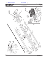
1600-SPC
14
b
9
2
15
18
17
c
16
2
d
a
13a
13
11
2
21a
20a
25
Lamination
roll
19a
19c
13a
Front
edge
26
21b
1c
12
11
b
10
9
19b
20b
25
a
d
8
1
22
2
24
3
23
c
4
5
13a
6
7
Picture 1 - GENERAL DESCRIPTION OF THE MACHINE
Ed. 05/01
I- 4
Index
1600-SPC
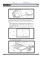
1.3 LAYOUT (picture 1)
1.4 ELECTRICAL CONTROL CABINET
The 1600-SPC laminator consists of the following
blocks:
a - A fixed front unit containing the input roller (13) on
which are mounted:
- the panel centering system (11) and insertion
system (1c) between the lamination rolls (20a/
b);
- the vacuum pump (5) for the vacuum sectors
(19a/b/c);
- the exhaust fan for the lamination fumes with an
air outlet;
- an exhaust fan (10) on the cap (9).
b -A fixed rear unit consisting of an output roller (14),
on which are mounted:
- an IR sensor (18) which reads the temperature
of laminated panels;
- a photocell (17) for detecting the output panel;
- the grounding bars for static electricity.
c - A removable central unit on which are mounted:
- the lamination rolls (20a/b);
- the vacuum sectors (19a/b/c);
- the tacking bars (21a/b);
- the cutting groups;
- the dry film rolls;
- the dry film dynamic tension rolls;
- the lateral cutting groups;
- the IR lamps for heating the lamination rolls;
- the protective cap (9).
d -A control cabinet mounted on wheels, containing
all the electrical commands, the display and the
keyboard (1).
(picture 1)
The 1600-SPC laminator is controlled by an Allen
Bradley PLC (1), series SLC, which interfaces to the
operator via a display with messages in his mother
tongue and a numerical keyboard.
The PLC is housed in the control cabinet (d) with all
the other electrical components and actuators.
The control cabinet is mounted on wheels, and can
be easily moved.
It is connected to the machine by multi-wire cables
and connectors.
It can be located either to the left or to the right of the
machine. In order to facilitate the operator’s work, it is
advisable, whenever possible, to place it to the right.
The universal power transformer of the control panel
makes it possible to use various network voltages
(see chapter “TECHNICAL FEATURES”).
NOTE
Should it be necessary to connect the machine to
voltages other than the one for which it has been
preset, our technical assistance office should first be
consulted for all necessary information.
The electrical control cabinet is fitted with three
panels where the electrical components are located:
• the main one in the rear;
• a secondary one hinged to the right side;
• a secondary one hinged to the left side.
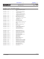
Key
a
b
c
d
-
1
2
3
4
5
6
-
Stable front unit
Stable rear unit
Removable central unit
Control cabinet
Allen Bradley display
Emergency push-buttons
Machine identification plate
Support feet
Vacuum pump
Lever for releasing the
removable unit
7 - Removable unit wheels
8 - Pneumatic
adjustment
control panel
9 - Cap of lexan
19a/b/c - Vacuum sectors
10 - Exhaust fan for fumes in the 20a/b - Lamination rolls
21a/b - Tacking bars
cap
11 - Shoulders of the centering 22 - Connection for compressed
air
unit
23 - Panel-to-machine
12 - Front barrier
connectors
13 - Input roller
24 - Exhaust hose coupling
13a- Folding input roller
14 - Output roller
25 - Removable central unit
15 - Flashing alarm lamp
26 - Insertion group
16 - Flexible exhaust hose
17 - Photocell for detecting output
panels
18 - IR sensor for reading the
laminated panel temperature
Ed. 05/01
I- 5I-1
Index
1600-SPC
1.5 MACHINE IDENTIFICATION
(picture 1)
- The serial number and identification data of the
machine are punched on a plate (3) fixed to the
frame on the left of the front side.
NOTE
Always indicate the serial number of the machine
when requesting technical servicing or when ordering
spare parts.
1.5.A Check at reception.
- After removing the packing, make sure that the
machine has not been damaged during transport.
- Check for damages to the machine structure and
for crushed, torn or broken electrical cables.
NOTE
Should damages to the machine or its accessories
be discovered, immediately inform in writing our
Technical Service Department or the Area Agent
(no later than 8 days after reception date).
1.6 PRELIMINARY
INSTALLATION
CHECKS
AND
1.6.A - Installation
Unit 1600-SPC, either installed alone or in line, must
be positioned in strict compliance with the indications
in the Table “OVERALL DIMENSIONS” which give
the minimum space required by the operator to carry
out correctly each work sequence and/or servicing
operation.
The machine is equipped with a power cable without
plug, and it is set to operate with a standard 380V
voltage (415/480/220/200V on request) - 50 or 60 Hz
three-phase plus ground.
It is possible to supply other voltages when ordering,
by previous agreement.
WARNING
Before connecting the power supply, make sure
that the characteristics of the electrical power
supply comply with the values on the identification
plate of the machine (pos. 3 picture 1).
NOTE
For the electrical wall connection, the power supply
line must be equipped with a switch as indicated in the
chapter “Technical Features”, and the cable section
must be adequate for such current value.
Voltage variations must not exceed ±7% of the rated
value.
Ed. 05/01
I- 6
Index
1600-SPC
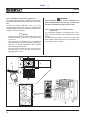
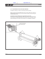
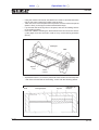
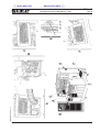
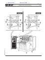
1.6.B Machine positioning and leveling (picture 2)
Place the machine in its established place, adjust its height and level the
conveyor height by means of the support feet (1) as follows:
1- Loosen the nuts (2) of all support feet of the unit.
2- Turn the feet to adjust the height of the machine and level the conveyor
height.
3- Once completed the operation, lock the feet in place by tightening the nuts
(2).
2
1
Picture 2 - HEIGHT ADJUSTMENT
Ed. 05/01
I- 7I-1
Index
1600-SPC
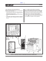
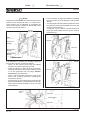
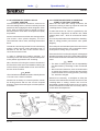
1.6.C Pneumatic connection (picture 3)
The coupling for pneumatic connection to the factory
air supply is placed externally at the bottom of the rear
side.
Connect the built-in ON/OFF valve (1) to the
compressed air supply line, bearing in mind that the
operating pressure of the machine is indicated in the
chapter “Technical features”.
NOTE
• A pipe with a minimum inner diameter of 8 mm and
external diameter of 10 mm is required for the
connection.
• The machine is supplied with the operating
pressure already set by the pressure regulator (2),
therefore no further adjustments are required
before starting the machine.
However, we recommend to check the value on
the manometer (3) to prevent pressure from
dropping below 5 atm.
WARNING
The pneumatic system of this Laminator has
been designed and built with dry components,
therefore lubricated air must not be used.
1.6.D - Connection of the exhaust hose
(picture 3)
The 1600-SPC laminator is equipped with a 5 m.
long, ø 150 mm flexible hose (5), and with two hose
clamps.
It is therefore necessary to connect one end of the
hose to the machine hose union (4) and the other end
to the main exhaust system.
5
1
2
3
4
Picture 3 - PNEUMATIC CONNECTION AND EXHAUST HOSE
Ed. 05/01
I- 8
Index
1600-SPC
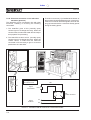
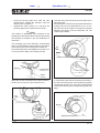
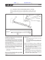
1.6.E - Electrical connection (picture 4)
In order to connect unit 1600-SPC to the main power
supply, proceed as follows:
• Connect the power cable to the main power supply,
having made sure that it is equipped with an
adequate grounding system.
• Place the control cabinet (1) on the most convenient
side.
• Insert all the control panel-to-machine connectors
(4) in their plugs, complying with the positions
printed.
1.6.F - Check of the electrical connection
After completing the electrical connection to the power
supply, turn the main power switch to position I .
An electronic device will check the correct connection
of the phases; an alarm message will appear on the
display in case of inverted or missing phases.
In this event, turn the main power switch back to
position O and invert two of the three phases of the
connection, then repeat the check operation.
1
Electrical
connection
power cable
5
3
4
4
3
2
Picture 4 - CONTROL PANEL-TO-MACHINE ELECTRICAL CONNECTION
Ed. 05/01
I- 9I-1
Index
1600-SPC
1.6.G - Electrical connection in line with other
machines (picture 5)
The 1600-SPC can be connected in line with other
machines, enabling or receiving the following
commands:
The built-in connector (1) is installed at the bottom of
the machine left side (besides the main connectors).
If there is no need to use these signals, leave its own
plug (2) inserted with the connection already preset
during the testing phase.
1- The 1600-SPC gives a N.O. (normally open)
contact signal of a voltage-free relay. When the
contact closes, it means that 1600-SPC is ready to
accept panels for processing.
2- The 1600-SPC receives a N.O. (normally open)
contact signal of a voltage-free relay. When the
contact closes, it means that the machines
connected in line are ready to give or to receive
panels from the 1600-SPC.
1
Drawings for
connection in line
LE2
LE1
2
signal
transmitted
signal
received
Rext
1
2
3
4
CN7
4-poles connector
24
E5
Picture 5 - CONNECTION IN LINE WITH OTHER MACHINES
Ed. 05/01
I- 10
Index
1600-SPC
2.1
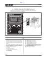
CONTROL PANEL ON THE CABINET (picture 6)
This section gives instructions on how to use correctly the commands and the
instruments on the 1600-SPC control panel.
a
9
b
1
c
e
d
3
5
2
6
7
4
9
8
Picture 6 - CONTROL PANEL
KEY
1 - Display “Panel View 900”
By means of the function keys (e) it is possible to
set and/or modify the machine functions, simply
by following the instructions as they appear on the
display.
The machine supervision is carried out by the
PLC, while autodiagnosis and/or information are
shown on the display by means of a series of
messages, listed in section 5.1.
a - Display
b - Numerical keyboard
c - Data confirmation key (Enter)
d - Cursor keys
e - Function keys
234567-
“MAIN POWER ON” white pilot lamp
“SET UP ON” push-button
“SET UP OFF” push-button
“CYCLE START” push-button
“CYCLE STOP” push-button
“LAMINATION SINGLE SIDE/BOTH SIDES”
two-position selector
8 - “TACKING BAR HEATING” potentiometer
9 - Emergency push-buttons
Ed. 05/01
II-A.1
Index
1600-SPC
2.2
CONTROL PANEL (picture 6)
2- MAIN POWER ON
This is a pilot lamp that indicates that there is
voltage present in the electrical panel. It lights up
when the main power switch at the rear of the
cabinet is closed.
3 - SET UP ON
This is a light button that enables all the machine
commands.
It turns off when SET UP OFF or one of the
emergency buttons is pressed, or when the
machine goes in a state of alarm.
It activates the heating of the lamination rolls and
of the tacking bars, the vacuum pump, the exhaust
fan, the cap ventilation (if on) and the lateral
cutting rewinding motors (if on).
WARNING
Before giving the SET UP ON command, make
sure that there is no dry film between the rolls.
6 - CYCLE STOP
This is an unlit button which unenables all functions
activated by CYCLE START.
7 - LAMINATION SINGLE SIDE-BOTH SIDES
This is a backlit selector that enables lamination
either on one or on both surfaces of the panel.
The selection must be made before the machine
set up.
8 - TACKING BAR HEATING
This is a potentiometer which regulates the heating
percentage of the rubber pads for tacking. At 0%
the pads temperature is the same as room temperature, at 100% it is approximately 45°C.
Its funcion is subordinated to SET UP ON.
9 - EMERGENCY PUSH-BUTTON
It is a button which stops all machine functions
instanty.
4- SET UP OFF
This is an unlit button which unenables the SET
UP ON functions.
5 - CYCLE START
This is a light button that starts the lamination
cycle.
It is subordinated to SET UP ON and sets in motion
the input roller and the centering unit and enables
all functions of the lamination cycle.
CYCLE START is unenabled by CYCLE STOP or
when the machine stops in an emergency.
The CYCLE START command is accepted only
once the central unit has been closed and the dry
film has been positioned on the vacuum sectors.
Ed. 05/01
II-A. 2
Index
1600-SPC
2.3
PUSH-BUTTON PANELS ON THE MACHINE (picture 7)
This section gives instructions on how to use correctly the commands on the pushbutton panels of the removable central unit.
1
LOADING OPERATION
ENABLE
FILM ROLLS
ON=FREE
3
FILM LOADING
SET-POINT
2
VACUUM
UPPER
LOWER
OFF ON OFF
4
Picture 7 - PUSH-BUTTON PANELS ON THE MACHINE
KEY
1- LOADING OPERATION ENABLE
This is a pilot lamp that indicates that the procedure for loading the dry film on the machine has been
enabled. It lights up when the machine is open and
the SET UP ON button has been pressed.
3 - FILM ROLLS ON = FREE
This is a light button that operates cyclically. The
first impulse releases the two dry film rolls, while
the second one locks them again.
The release is signalled by the light in the button.
2 - FILM LOADING SET-POINT
This is an unlit button that enables the procedure
for loading the dry film coils.
It is subordinated to SET UP ON and the machine
being open.
First turn by hand the rotating sectors to position
“Awaiting-Start of cutting”, then press this button
in order to fix the indexes in the slots of the cams.
If this command generates an acoustic alarm, it
means that the rotating sectors are not in the right
position of “Awaiting-Start of cutting”; place them
in the correct position, press the button again, then
start the loading procedure.
4 - VACUUM UPPER OFF/ON /LOWER OFF
This is a three-position light selector that inhibits
vacuum in the main vacuum sectors to facilitate
dry film loading.
In order to operate in the automatic mode, it is
necessary to turn this selector back to its central
position (ON).
Ed. 05/01
II-B.1
Index
1600-SPC
2.4
PNEUMATIC ADJUSTMENT CONTROL PANEL (picture 8)
This section gives instructions on how to use correctly the commands and the
instruments on the control panel placed on the right side of the machine.
1
2
3
5
4
6
7
9
8
10
Picture 8 - PNEUMATIC ADJUSTMENT CONTROL PANEL
KEY
1- UPPER ROLL TEMPERATURE CONTROL
This is the thermoregulator for setting and checking
the temperature of the upper lamination roll.
2 - LOWER ROLL TEMPERATURE CONTROL
This is the thermoregulator for setting and checking
the temperature of the lower lamination roll.
3 - “LAMINATION PRESSURE” manometer
This manometer indicates the pressure of the
lamination rolls.
4 - “LAMINATION PRESSURE” regulator
This is the regulator for the pressure of the
lamination rolls.
5 - “LATERAL CUTTING” selector
This selector enables the lateral cutting.
6 - “VENTILATION” selector
This selector activates ventilation in the cap.
7 - “UPPER FILM STATIC TENSION” manometer
This manometer indicates the tensioning pressure
of the upper dry film.
8 - “UPPER FILM STATIC TENSION” regulator
This is the regulator for the tensioning pressure of
the upper dry film.
9 - “LOWER FILM STATIC TENSION” manometer
This manometer indicates the tensioning pressure
of the lower dry film.
10 - “LOWER FILM STATIC TENSION” regulator
This is the regulator for the tensioning pressure of
the lower dry film.
Ed. 05/01
II-B. 2
Index
1600-SPC
3.1 OPERATOR GUIDE FOR START UP
H) Verify or set the roll temperature.
A) Turn on the machine with the main power switch.
B) The machine will carry out the initial system checkcontrol, then the display will show the message
“EVERYTHING OK”.
C) Take out the removable unit.
D) Start the machine by pressing the “SET UP ON”
button.
E) Reposition the rotating sectors; the vacuum system
will activate to hold the dry film.
F) Place the dry film on the dry film rolls and load it
following the diagram on the machine.
Center the dry film using the centering scale. Trim
the leading edge of the dry film on the counterblade,
being careful not to damage the pad on the tacking
bar.
I) Verify and, if necessary, adjust the lamination roll
pressure.
J) Verify or set the lamination parameters.
K) Press the CYCLE START button to start the input
roller and accept input panels.
L) Whenever a cycle is started, check the first
processed panel for correct lamination and edges.
NOTE
Maintenance and periodic cleaning operations on the
machine are extremely important to ensure its correct
functioning and for good quality of the processed
panels. It is strongly recommended to carry out with
utmost care all the operations indicated in the
Maintenance Table of this manual; it is advisable,
moreover, to affix a copy of the Table on the machine
itself.
G) Close the removable unit to allow the heating of
the lamination rolls.
Ed. 05/01
II-C.1
Index
1600-SPC
K
EFT
N
BLA
YL
ALL
ON
S
THI
E
PAG
TI
N
E
T
IN
Ed. 05/01
II-C.2
Index
1600-SPC
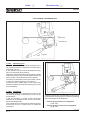
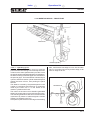
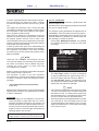
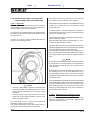
3.2 OPERATING CYCLE
The panel for lamination arrives on the input roller,
where it is centered onto the machine center line by
the “Soft-Contact” centering unit.
It then stops against a frontal barrier which lines it up
with the lamination rolls.
The panel is gripped between two rolls, and inserted
between the vacuum sectors, which also include the
tacking bars and the counterblades of the shears.
Here the dry film is tacked on both sides of the panel
as per the set time and temperature.
After tacking, the sectors and the tacking bars separate, leaving the dry film stuck to the panel.
Then they rotate to allow the lamination rolls to close
down onto the panel precisely at the point of tacking.
Lamination roll
Front
edge
Ed. 05/01
II-D.1
Index
1600-SPC
The tension rolls stretch the dry film, and the lamination rolls start to laminate the
dry film on the panel. When the PLC send the signal to cut, the vacuum sectors
and the counterblades begin moving again following the dry film.
Simultaneously the shear blades close down on the counterblades and cut the
dry film.
Start of
cutting
End of
cutting
Panel
Scheda
Once the panel has been completely laminated, the rolls separate and, if there
is another panel ready for lamination, the vacuum sectors return to the tacking
position.
Meanwhile, the laminated panel has reached the output roller, where its static
electricity is discharged and its temperature is read by an IR sensor.
Ed. 05/01
II-D.2
Index
1600-SPC
3.3 OPERATIONS OF THE VARIOUS GROUPS
3.3.A
3.3.B
3.3.C
3.3.D
Lateral centering unit. ...............................................................
Frontal centering unit. ...............................................................
Insertion group-front edge. ......................................................
Rotating sectors - vacuum pump - tacking bars
and counterblade. ....................................................................
3.3.E Electric cams phase diagram. ..................................................
3.3.F Rotating sectors in tacking position. ........................................
3.3.G Rotating sectors in rolls closed position. ..................................
3.3.H Rotating sectors in awaiting-start of cutting position. ...............
3.3.I Coupling of the cutting groups (start of cutting). ......................
3.3.J Rotating sectors in end of cutting position. ..............................
3.3.K Cutting groups at the end of cutting and their uncoupling. .......
3.3.L Cutting on the fly-rear edge-rear edge photocell.. ...................
3.3.M Calibration of the roll speed .....................................................
3.3.N Calibration of the rear edge photocell. .....................................
3.3.O Alignment of the rear edge on both faces
(upper and lower). ....................................................................
3.3.P Calculation of the rear edge-correction of parameters
and cycle times. .......................................................................
3.3.Q Cycle times. .............................................................................
3.3.R Edges on panels of minimum length. .......................................
3.3.S Cutting groups. .........................................................................
3.3.T Lamination rolls, pressure, heating and thermal
alarm message. .......................................................................
3.3.U Display of the output panel temperature. .................................
3.3.V Vacuum cutoff valves. ..............................................................
3.3.W Dynamic tension rolls. ..............................................................
3.3.X Static tensioning unit (frictions). ..............................................
3.3.Y Lateral cutting. .........................................................................
II - F.1
II - F.4
II - F.5
II
II
II
II
II
II
II
II
II
II
II
- F.7
- F.8
- F.9
-F.14
-F.14
-F.15
-F.18
-F.19
-F.21
-F.22
-F.23
II -F.23
II
II
II
II
-F.24
-F.26
-F.27
-F.28
II
II
II
II
II
II
-F.31
-F.35
-F.35
-F.37
-F.39
-F.40
Ed. 05/01
II-E.1
Index
1600-SPC
NK
LA
TB
EF
YL
ALL
ON
AGE
P
S
I
TI
TEN
IN
TH
Ed. 05/01
II-E.2
Index
Operations list
1600-SPC
3.3.A LATERAL CENTERING UNIT
3.3.A.1 - Operating cycle
The lateral centering unit is powered by a low inertia D.C. micro-motor and a toothed
belt. The motor is controlled by an electronic circuit board (S.C.C.) and by two pairs
of photocells (installed on the lateral shoulders) plus another photocell, called
intercepting photocell.
Intercepting
photocell
Slowing - down
photocell
Mirrors
Intercepting
photocell
Stop photocells
Slowing - down
photocell
DC Motor
When the panel reaches the intercepting photocell
(FC69), its presence is signalled to the control panel
(S.C.C.). The motor (M5) sets the two lateral shoulders
in motion so that when they close they move the panel
towards the center of the machine.
When both slowing-down photocells (FC75/76) have
been activated by the panel, the motor decelerates
immediately, slowly bringing the lateral shoulders
near to the panel until the two stop photocells are
activated (FC74/FC77).
Servo control for DC motor
PLC
The motor (M5) stops for the period of time selected
on the control panel (S.C.C.). Then, inverting its
rotation, it opens the lateral shoulders again and
finally stops when the backward stop sensor (FC70)
is activated.
Should either the forward movement stop sensor
(FC71) or the backward movement stop sensor (FC70)
not function for any reason, the safety microswitches
(FC72/FC73/FC73A) will take over, cutting off
immediately the power supply to the motor and
activating a failure message.
Ed. 05/01
II-F.1
Index
Operations list
1600-SPC
3.3.A.2 - Adjustments and calibration of the
lateral centering unit
For the correct functioning of the lateral centering
unit, it is necessary to allow some gap between the
shoulders and the panel when the centering unit is
closed.
Calibrate this space as follows:
• switch off the machine and disconnect only one of
the cables of the micromotor (M5) placed at the top
of the front left crankcase;
• turn on the machine again and, slowly moving the
lateral shoulders by hand, center a rigid, wellsquared panel, taking care to stop immediately as
soon as the stop photocells FC74 and FC77 (left
and right) turn off;
• check, in these conditions, the amount of gap
between the lateral shoulders rolls and the panel;
• adjust the supports of the stop photocells either to
increase or to decrease the gap; the recommended
total gap is approximately 1 mm.
It is equally important to check the parallelism of the
two lateral shoulders using the same rigid panel. If
necessary, adjust their position operating on their
fastening screws .
The correct reading distance for the forward and
backward movement stop sensors (FC71-FC70) is
1.5 mm. Their position can be adjusted operating on
their sensor-holder blocks, which should be locked in
place again after the operation.
NOTE
Should the overtravel microswitches (FC72-FC73FC73A) become activated, it will be necessary to
remove the cause (e. g., misplacement of the
movement stop sensors, or their failure), and then to
release the centering unit by hand.
In order to achieve a precise positioning of the
centering, it is very important that the shoulders slow
down distinctly once both photocells (left and right)
FC75 and FC76 have been activated.
Therefore it is necessary to calibrate the value of
“low” speed very carefully, using potentiometer LT.
On the other hand, with potentiometer RM it is possible
to calibrate the off cycle time of the lateral shoulders
once the panel has been centered.
The maximum cycle time can be determined with
potentiometer CL. Once this time has expired, the
centering unit reopens, even if the panel has not been
centered yet. This is useful, in that it prevents the
motor from overloading in the event of mechanical
blockage of the centering unit, or any other failure.
The cycle time allowed should, however, always be
longer than the real time needed to center the panel,
including off cycle time, otherwise the centering unit
would be unable to complete its run and its off cycle
pause correctly prior to reopening.
Potentiometer RT, finally, allows to set the off cycle
time of the centering unit between one command to
close, generated by the intercepting photocell, and
the next.
NOTE
Should it be necessary to replace the electronic
circuit, all the potentiometers must be recalibrated,
“copying” their positions from the previously used
electronic circuit.
In order to protect the transistors that power the motor
from overheating, their dissipator has been equipped
with a 70°C thermal switch.
This thermal switch stops the machine in emergency
state, and activates the alarm message:
• “Lateral centering failure” (code 421).
The same alarm message is displayed when one of
the overtravel microswitches (FC72/FC73/FC73A) is
activated.
Ed. 05/01
II-F. 2
Index
Operations list
1600-SPC
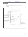
The electronic board which controls the centering unit cycle has the following
configuration:
power input
output voltage
(non-stabilized) output voltage
manual
motore
motor
motore
motor
FC72/FC73/FC73A centering unit overtravel
(centering unit failure) relay contact
relay contact
low speed adjustment
24VDC RELAY
FC74 left stop photocell
FC77 right stop photocell
set up ............................................................
FC69 (A4) intercepting barrier photocell .......
FC75 left slowing-down photocell .................
FC76 right slowing-down photocell ...............
FC71 centering unit closed ...........................
FC70 centering unit open ..............................
A3
A4
PHOTOCELL
PHOTOCELL
AMPLIFIER
AMPLIFIER
return speed
modification
mirror photocell delay
cycle time
return time
FC69 barrier photocell
set up
FC 75 left slowing-down photocell
FC 76 right slowing-down photocell
FC 71 centering unit closed
FC 70 centering unit open
Ed. 05/01
II-F.3
Index
Operations list
1600-SPC
3.3.B FRONTAL CENTERING UNIT
Insertion roll
Frontal barrier
Cylinder
3.3.B.1 - Operating cycle
The alignment of the panel and the lamination line is
very important when it is required to laminate with a
front edge of 0 mm.
In this case the dry film must not be detached in any
way from the panel during tacking.
Alignment is achieved by allowing the panel, pushed
forward by the input rollers, to lean against the frontal
barrier where it automatically becomes aligned.
This barrier is lowered by its own pneumatic cylinder
in order to insert the panel into the machine.
The barrier will be raised again once the panel has
passed completely through the insertion group (see
picture besides).
3.3.B.2 - Calibration
The misalignment of the panel with the rolls can be
corrected by working on the fastening screws of the
frontal barrier.
It will be necessary to make minute successive
adjustments, and measure each time the result with
some laminated panels.
The cylinder which moves the barrier has two sensors
(FC18 and FC19) for forward and for backward
movement.
If neither of these are activated within a time limit of
5 seconds from the movement command, the following
alarm messages will be displayed:
• “Barrier up movement not completed”
(code 180)
• “Barrier down movement not completed”
(code 190).
Ed. 05/01
II-F. 4
Index
Operations list
1600-SPC
3.3.C INSERTION GROUP - FRONT EDGE
Insertion roll
Front barrier
Insertion cylinder
3.3.C.1 - Operating cycle
The task of the panel insertion group is to push the
panel between the tacking bars. Normally the lower
roll turns at the same speed as the input roller. Once
the panel has been aligned against the frontal barrier,
the lower roll stops, while the upper one is lowered on
the panel to grip it. The frontal barrier is lowered by its
cylinder, while the insertion cylinder extends fully and
makes the lower roll turn, thus pushing the panel
forward.
The distance covered by the panel depends on the
number of revolutions and fractions of revolutions
made by the lower roll, i.e. on the stroke of the
insertion cylinder and its rack.
The motion of the lower roll is therefore generated
either by the input roller or by the rack insertion group.
The switching between these two movement forces
is achieved by means of electromagnetic clutches
(FZ5-6-7) activated by the PLC.
If the panel is pushed to the exact edge of the tacking
bars, it will have a front edge of 0 mm. On the other
hand, if it is pushed 50 mm beyond this edge, it will
have an edge of 50 mm.
Front
edge
Bordo
anteriore
Bordo
anteriore roll
Lamination
Ed. 05/01
II-F.5
Index
Operations list
1600-SPC
In order to calibrate the stroke of the insertion cylinder,
and consequently the panel front edge, a sliding
mechanical register has been fixed to the cylinder
rod.
This register is powered by a D.C. micromotor (M6)
controlled by an electronic circuit (AZ3), which receives
the information on the exact position of the register
from a position transducer (P6).
When the PLC transmits a command to move the
register to a certain position, the positioner compares
the present position and the one to reach, then
commands the motor to turn one direction or the other
until the transducer transmits the information that the
new position has been reached.
In order to prevent the group from overshooting the
limit of its mechanical stroke because of some failure,
two overtravel microswitches have been installed
(FC100/FC110); when activated, they stop the motor
(M6) immediately.
NOTE
When the two overtravel microswitches (FC100/
FC110) are activated, it is necessary first to eliminate
the cause of the failure, then to release the group,
rotating the motor gears by hand until the
microswitches are cleared.
3.3.C.2 - Calibration
The ratio between the insertion cylinder stroke and
the front edge is 1.66.
Therefore 10 mm of front edge on the panel correspond
to 6 mm of cylinder stroke.
The insertion group guarantees the highest level of
repeatability of the front edge over the long period.
Nevertheless, should it become necessary to correct
possible differences between the preset edge and
the real edge, proceed as follows:
- On the page “Modify Preselectors” it is possible
to correct the offset of “Pos. 0” and “Pos. 50” of the
front edge.
AUTOMATIC
LAMINATOR
1600 - SPC
MODIFY PRESELECTORS
F1
TACKING ENRICHMENT....................................................... T1: 32
F2
UPPER SUPPLEMENTARY ENRICHMENT ....................... T2: 30
F3
LOWER SUPPLEMENTARY ENRICHMENT...................... T2: 12
F4
SET POINT ENRICHMENT..................................................... T2: 10
F5
REAR EDGE CORRECTION .................................................. Y : 28
F6
REAR EDGE CORRECTION .................................................. X : 40
F7
FRONT EDGE CORRECTION............................................... POS. ø : 61
F8
FRONT EDGE CORRECTION............................................... POS. 50: 39
Exit: SET UP ON
Also the control circuit of this group has been equipped
with a thermal switch, set at 70°C.
The activation of either of the two overshoot
microswitches or of the thermal switch will stop the
machine in emergency state, and display the alarm
message:
• “Front edge device movement failure”
(code 381).
Replacement of the electronic circuit of the front edge
register does not require any readjustment of offsets
or electric calibration.
Front edge:
The front edge can vary between 0 and 50 mm
only if the panel is longer than 250 mm. This is
because the distance between the insertion roll
and the lamination line is approximately 200 mm.
Since the machine accepts panels with minimum
length of 210 mm, the front edge should take the
following relation into account:
- The “Zero edge” position, to which corresponds
an equal measurement for panel and dry film, is
set on the display with the reference “Pos. 0”.
- The “50 mm edge” position, corresponding to 50
mm of panel uncovered by the dry film, is set on the
display with the reference “Pos. 50”.
NOTE
• The operator must therefore first set a front edge
of 0 mm on the display, then increase the figure of
the reference “Pos. 0” if the dry film is longer than
the laminated panel, or decrease the figure if the
dry film is shorter than the laminated panel.
• Once the position for zero edge has been corrected,
it is necessary to set a front edge of 50 mm and
increase the figure of the reference “Pos. 50” if the
edge is less than 50 mm, or decrease it if the edge
is more than 50 mm.
• Maximum possible front edge =
length of panel - 210 mm (not more than 50 mm)
Ed. 05/01
II-F. 6
Index
Operations list
1600-SPC
3.3.D ROTATING SECTORS - VACUUM PUMP TACKING BARS AND COUNTERBLADE
The lower unit does not need to be under vacuum
because the dry film adheres to it by gravity.
3.3.D.1 - Operation
The function of the upper and lower vacuum sectors
is to hold the dry film and convey it from the start of
cutting position to the tacking position.
Both the tacking bars and the counterblades are fixed
to the main vacuum sectors, and therefore rotate
jointly with them.
A vacuum pump, installed in the front compartment of
the machine, ensures that the dry film adheres to the
vacuum sectors.
Vacuum is cut off by valves installed between the
pump and the rotating sectors.
A rotating mercury connector (Mercotac), placed on
the left side of the vacuum sectors, provides electrical
power to the tacking bars.
The resistive element for heating the tacking bars is
placed inside the rubber.
Each element has a value of approximately 17 and
a power of approximately 150W.
The heating elements are powered with a 50V voltage,
and are equipped with a device (SRT) which regulates
their ratio between time ON and time OFF.
The analogue regulation has a range between 0%
and 100%. At 0% the tacking bars temperature equals
room temperature, and at 100% it is approximately
45°C.
NOTE
It should be noted that the tacking bars temperature
is influenced by the temperature of the lamination
rolls, therefore variations from the declared values
may be found.
It should also be remembered that the temperature of
the tacking bars is not all that determinant for a
successful lamination process. This is due to the fact
that after tacking the panel does not move on until rolllamination starts.
NOTE
• Vacuum in the vacuum sectors is cut off during the
lamination phase, and restored when the vacuum
sectors start to rotate again to carry out the cutting
operation.
• Vacuum is kept in the vacuum sectors from the
beginning of the cutting operation until the next
tacking has taken place.
The secondary vacuum sectors are positioned
beneath the main vacuum sectors.
The upper unit holds the dry film after it has been cut,
to prevent it from falling back onto the panel.
The counterblades of the shearing system are screwed
to the tacking bars, therefore they move together with
the entire rotating sector when a cut has to be made.
Both rotating groups are moved by the main motor
through an electromagnetic clutch (FZ1) situated on
the left side of the machine.
3.3.D.2 - Adjustment and calibration of the
positions of the rotating sectors
The rotating sectors, together with the tacking bars
and the counterblades, have three different stop
positions during the cycle.
Ed. 05/01
II-F.7
Index
Operations list
1600-SPC
3.3.E ELECTRIC CAMS PHASE DIAGRAM
FC 39 Cam for closing lamination rolls
FC 31 Cam for sectors slowing-down position
FC 30 Cam for end of cutting position
FC 29 Cam for tacking position
FC 28 Cam for start of cutting position
20
FC 39
FC 31
FC 30
10
10
0
20
190°
287°
0°
FC 29
78°
FC 28
335°
Ed. 05/01
II-F. 8
Index
Operations list
1600-SPC
3.3.F ROTATING SECTORS IN TACKING POSITION
The phase is read by an electric cam and by its sensor (FC29).
When the sensor (FC29) identifies the slot in its own electric cam, the PLC
disengages the clutch for the sectors and inserts the indexes into the tacking slot
of the mechanical cam.
The position and its repetitivity is thus guaranteed by the index.
Should it be necessary to anticipate or delay the command to activate the index,
it can be done by changing the position of the electric cam connected to sensor
FC29, fastening the cam with its own screws once completed the operation.
Sensors and cams for
the operating cycle
Ed. 05/01
II-F.9
Index
Operations list
1600-SPC
NOTE
The position of the electric cam does not influence the
position of the mechanical cams or of the sectors.
Their position can be adjusted by regulating the
tishes of the indexes, situated on the left side of the
machine (see picture below).
Cilindro
Cylinder
• If it is necessary to adjust this distance, separate
the two sectors by unenabling the electrovalve
(EV19).
• Turn the upper and lower tishes clockwise to move
the pads (or tacking bars) toward the rear of the
machine (see picture a);
conversely, turn the tishes counterclockwise to
move the pads toward the front of the machine
(see picture b).
FIG. A
Index
Tishe
Lato side
Front
anteriore
Posizione di
Tacking
Lato
Rear
side
posteriore
End
of cutting
Posizione
di
position
Start
of cutting
Posizione
di
position
Mechanical
cam
Camma
meccanica
It is important to perform this operation with the
utmost care and skill. Proceed as follows:
• Switch off the machine and bring the rotating
sectors to the tacking position by hand.
• Insert the indexes, in order to block the sectors,
activating the electrovalve (EV25) either by hand
or via the keyboard from the page “Manual
movements” (see flowchart).
• Insert a panel between the sectors, then close
them as for a tacking operation, activating the
electrovalve (EV19).
• Go to the rear of the machine and check that the
distance between the counterblades and the rear
edge of the machine shoulder is 347.5 mm (see
picture below).
Tacking
bars
FIG. B
Lato
Front
side
anteriore
Front
side
Rear
Latoside
posteriore
347,5 mm
Counter blades
347,5 mm
Ed. 05/01
II-F. 10
Index
Operations list
1600-SPC
• Close the sectors again and read the new
measurement. Repeat the operation until the
desired value is obtained.
• Calibrate the lower sectors, too, until they are
perfectly aligned, then fasten the two tishes.
NOTE
The position of the tacking bars compared to the
tangent line of the rolls is a decisive factor in preventing
the formation of bubbles in the first millimetres of
lamination.
The operating cycle of the laminator, as described
above, requires that the rolls close down on the panel
at the exact point where tacking was carried out.
Due to the width of the counterblade, the dry film is cut
3 mm beyond the edge of the tacking bar pad.
This strip of dry film must thus be stuck down by the
lamination rolls.
If the lamination rolls close on the panel ahead of the
tacking area, the air underneath the 3 mm of nonstuck dry film will be unable to escape and, trapped
between the tacking and the lamination roll, will
create large bubbles.
Lamination roll
Dry
film
Panel
Scheda
Tacking
Tacking bar
Dry film
Counter blade
Aria
Air
Blade
When the dry film is tacked on the panel, therefore,
the first 3 mm of dry film cannot be stuck to it.
If, on the other hand, the roll comes down precisely on
the end of the tacking line, as its rubber is gradually
compressed, these 3 mm of dry film will be pressed
on the panel, allowing air to escape through the front
edge.
Dry
film
Panel
Scheda
Lamination
roll
Tacking
Dry film
Air
Ed. 05/01
II-F.11
Index
Operations list
1600-SPC
Dry film
Since the roll footprint is approximately 9 mm, while the tacking footprint is only
3 mm, when the roll presses down, it can completely cover both the dry film strip
already stuck by tacking and the 3 mm strip that has not adhered yet.
It is possible to check the precise position of the pads compared to the rolls as
follows:
• Switch off the machine, remove the central unit and turn the rotating sectors
by hand, bringing them to the position opposite the one of tacking.
• Take a rigid panel and lay a piece of dry film over it, attaching it by hand to
only one side of the panel.
• Using a knife, make a vertical cut along the dry film without detaching it from
the panel.
Panel
Scheda
DryDry
- Film
film
Cut
Taglio
• Insert the panel between the lamination rolls, keeping one of the two strips
of dry film folded back from the panel.
Lamination roll
Dry film
Panel
Scheda
Ed. 05/01
II-F. 12
Operations list
Index
1600-SPC
• Using the manual commands, activate EV19 in order to close the lamination
rolls on the panel; reopen them after a few seconds.
• Take care not to move the panel from its position once the rolls have opened
(attach it firmly to the support rollers with adhesive tape).
• Lay the other half of the dry film on the panel, and turn the rotating sectors
to the tacking position.
• Insert the indexes activating the electrovalve EV25 and close the sectors
(=rolls) again for a few seconds in order to carry out the tacking operation
(EV19).
Tacking bar
Roll
Dry film
Panel
Scheda
• Separate the sectors, remove the panel and check whether the two footprints
- that of the rolls and that of the tacking - match with the following sketch:
Panel
Scheda
Foot
print
tacking
Tacking
footprint
Dry film
Lamination roll
Foot print rulli
footprint
Ed. 05/01
II-F.13
Index
Operations list
1600-SPC
3.3.G ROTATING SECTORS IN “ROLLS
CLOSED” POSITION
Once the tacking has been carried out, vacuum is cut
off in the rotating sectors, which move away from the
panel and, after engaging the electromagnetic clutch
(FZ1), begin to rotate at their top speed in order to
allow the rolls to close down on the panel as rapidly
as possible.
As soon as the sectors reach the rolls closing position
(see electric cams phase diagram), the PLC
commands the rolls to close, activating electrovalve
EV19.
The electric cam which gives the PLC the rolls closing
position, called “cam for closing lamination rolls”, is
situated on the left side of the machine and is
connected to sensor FC39.
In order to calibrate this position precisely, it is
necessary to turn the sectors by hand and stop them
in the position opposite the one of tacking.
Next, close the rolls using the manual command of
EV19 and move the sectors backwards until they get
to the minimum possible distance from each other at
the rear of the machine.
NOTE
Check whether sensor FC39 is able to identify the slot
of its own cam in these conditions.
Should it be necessary to correct its position, loosen
the locking screws and turn the cam the required
direction. Tighten the screws again once the operation
is finished.
3.3.H ROTATING SECTORS IN “AWAITINGSTART OF CUTTING” POSITION
When the rolls start their closing movement, the
sectors are turning at their top speed to reach the
“Awaiting-Start of cutting” position.
To allow the sectors to come to a gradual stop, the
PLC receives a signal from an electric cam, called
“slowing-down cam”, which is connected to sensor
FC31.
This cam is positioned as to be ahead of the “AwaitingStart of cutting”position (see electric cams phase
diagram).
From this point onwards the speed of the two sectors
is reduced until the electric cam connected to sensor
FC28 (start of cutting cam) is activated.
As soon as the PLC receives this signal, it disengages
the electromagnetic clutch (FZ1) of the rotating sectors
and inserts the indexes in the slots of the mechanical
cams.
NOTE
• The start of cutting position and its repeatability
are determined by the design of the mechanical
cam.
• We recommend, therefore, never to use the tishes
to change this position, because also the tacking
position and the end of cutting position, previously
set, would be changed.
Should it be necessary to anticipate or delay the
insertion of the indexes into the mechanical cams, the
“Awaiting-Start of cutting” electric cam must be
anticipated or delayed with respect to its own sensor
FC28. Remember to fasten the cam firmly with its
screws after this adjustment.
Tishe
See electric
cams phase
diagram
Cylinder
Index
Start of cutting
cam
End of cutting
Start of cutting
Tacking
Slowing-down
cam
Ed. 05/01
II-F. 14
Index
Operations list
1600-SPC
3.3.I COUPLING OF THE CUTTING GROUPS (START OF CUTTING)
When the rotating sectors are in the “Awaiting-Start of cutting” position, the
upper and the lower cutting groups are coupled to them by means of the movable
blades.
Blade
Counterblade
Internal view of the cutting area
Counterblade
Blade
The coupling of the groups to the sectors allows them
to be drawn, moving in synchronism, following the dry
film during the cutting phase.
The coupling is possible because the movable blade
is placed obliquely by the first of the two cylinders
which make up the blade movement. The coupling
process is managed by the electrovalve EV20 for the
upper and the lower cuts.
The position where coupling (or uncoupling) takes
place is detected by two sensors, FC26 for the upper
cut and FC27 for the lower. If the two sensors are not
activated (or unenabled) within the time limit of 5 sec.,
the PLC stops the machine in emergency state,
displaying the alarm message:
• “Top & bot cut hooking movement failure”
(code 2670).
Once the coupling has taken place, the movable
blades and the counterblades must not get in touch
until the sectors start to move.
Therefore, between the two blades there should be a
clearance of:
• 2 mm (upper and lower) without any panel
between closed rolls;
• 0.7 mm (upper and lower) with 3 panels, each
1.6 mm thick, (total 4.8 mm) placed between
closed rolls.
Should it be necessary to verify or calibrate this
distance, the recommended procedure is as follows:
1. Switch off the machine, take out the removable
central unit, and place the rotating sectors in the
position opposite the one of tacking.
2. Close the lamination rolls by means of the manual
command of EV19, without inserting any panel
between them.
3. Turn the sectors by hand to the “Awaiting-Start of
cutting” position, and activate manually the
electrovalve EV25 in order to insert the indexes
into the slot of the mechanical cams.
Ed. 05/01
II-F.15
Index
Operations list
1600-SPC
4. Move by hand the two cutting groups (upper and lower) into the space
between the main and the secondary vacuum sectors.
5. Keeping them firmly in this position, give the command to couple the cutting
groups by activating the electrovalve EV20 (upper and lower).
6. Release the two cutting groups and let them come slowly to set point.
2 mm without panel
2 mm senza scheda
0,7 mm with 4,8 mm thick
panel
7. Using a thickness gauge, check that the distance between the coupling tooth
of the movable blade and the counterblade is as indicated in the above table
(2mm).
8. Should it be necessary to correct such distance, adjust it by working on the
right and left rear stops of each cutting group.
Ed. 05/01
II-F. 16
Index
Operations list
1600-SPC
Cylinder
Rear stop for the cutting groups
Rod adjustment
9.
Bring manually the cutting groups back towards the center of the vacuum
sectors and uncouple them by deactivating EV20, then return them to their
set point position.
10. Remove the indexes and open the rolls.
11. Insert three 1.6 mm thick panels between the rolls, then repeat the entire
procedure starting from point 2., checking that the distance between the
coupling tooth of the blades and the counterblades is correct (0.7 mm) for
both the upper and the lower units.
12. In order to ensure a stable coupling between the blades and their
counterblades as the rotating sectors turn during the cutting phase, the
upper return cylinders of the cutting groups move the opposite direction,
thus offering resistance to the rotatory motion of the sector itself.
Due to the effect of gravity, the lower group does not need any help from its
cylinder, as its own weight is sufficient.
In any case, it is advisable that the resistance force should not be excessive,
because it could slow down or even stop the movement of the rotating sectors.
NOTE
The pressure of the upper return cylinders is 6 atm. Its regulator is situated on
the left side of the machine rear.
Ed. 05/01
II-F.17
Index
Operations list
1600-SPC
3.3.J ROTATING SECTORS IN “END OF
CUTTING” POSITION
The dry film is cut by shears between the start of
cutting and the end of cutting positions.
During their movement, the rotating sectors have
also drawn with them the two cutting groups, extending
the cylinder rods attached to them.
NOTE
• Both the end of cutting position and its repeatability,
and the start of cutting position are determined by
the design of the mechanical cams.
• It is therefore advisable never to work on the tishes
to vary these positions, otherwise the positions of
tacking and “Awaiting-Start of cutting” will also
have to be changed.
Should it become necessary to anticipate or delay the
insertion of the indexes in the mechanical cams, the
end of cutting electric cam must be anticipated or
delayed with regard to its own sensor FC30,
remembering to fasten it firmly with its screws after
the adjustment.
Start of cutting position
End of
cutting
position
Panel
Once sensor FC30, connected to the end of cutting
electric cam, has identified the slot, the PLC
disengages the electromagnetic clutch (FZ1), thus
depriving the rotating sectors of their motion, and
activates the electrovalve EV25 to insert the indexes
into the slots of the mechanical cams.
Tishe
Cylindrer
Index
End of cutting
Start of cutting
Tacking
End of cutting cam
Ed. 05/01
II-F. 18
Index
Operations list
1600-SPC
3.3.K CUTTING GROUPS AT THE END OF
CUTTING AND THEIR UNCOUPLING
At the end of the cutting operation, when the rotating
sectors remain in their end of cutting position with the
indexes inserted, the blades and the counterblades
are tightly close along their entire length.
Ideal distances should be:
2.0 mm (upper and lower)
with no
panels between closed lamination
rolls.
0.7 mm (upper and lower)
with three
1.6 mm thick panels, (=4.8 mm)
between closed lamination rolls.
Counterblade
Blade
Counterblade
Blade
In order to return the cutting groups to their set point
position (start of cutting position), the PLC will detach
the blades from the counterblades by extending the
return cylinders, then it will reposition the blades from
oblique to parallel, thus uncoupling them from the
rotating sectors and, finally, will command the reentry of the two return cylinders.
NOTE
It is necessary that when the return cylinders of the
cutting groups are fully extended, there is enough
space between the blades and the counterblades to
prevent them from rubbing against each other.
This distance will vary according to the thickness of
the panels passing between the lamination rolls.
2 mm without2panel
mm senza scheda
con
da 4,8 mm
0,7 0,7
mmmm
with
4,8scheda
mm thick
panel
If it becomes necessary to verify this distance, proceed
as follows:
1. Switch off the machine, take out the removable
central unit and turn the rotating groups to the
position opposite the one for tacking.
2. Close the lamination rolls, activating by hand the
electrovalve EV19, without inserting any panel
between the rolls.
Ed. 05/01
II-F.19
Index
Operations list
1600-SPC
3. Turn by hand the rotating sectors to the end of
cutting position and activate manually the
electrovalve EV25 in order to insert the indexes
into the slots of the mechanical cams.
4. Move by hand the two cutting groups (upper and
lower) into the space between the main and
secondary vacuum sectors.
9. Detach the cutting groups from the rotating sectors
by unenabling the electrovalve EV20, and bring
them back to their set point position by unenabling
EV21.
10. Remove the indexes and open the rolls.
11. Insert three 1.6 mm thick panels between the rolls
and repeat the entire procedure starting from
point 2., and check that the distance between the
coupling tooth of the blades and the counterblades
is correct, i.e. 0.7 mm, for both units (upper and
lower).
Care should be taken to operate the return cylinders
of the cutting groups at the correct pressure.
Read the note in the chapter “Coupling of the cutting
groups”.
5. Activate by hand the electrovalve EV21 in order to
extend the return cylinders of the cutting groups.
6. Give the command to couple the cutting groups by
activating the electrovalve EV20.
7. Using a thickness gauge, check that the distance
between the coupling tooth of the movable blade
and the counterblade is as indicated in the Table
(2 mm).
8. Should it prove necessary to adjust this distance,
use the adjustment screws on the cylinder rods.
WARNING
Whenever the adjustment screws of the cylinder
rods are used, then the coupling-start of cutting
position should also be checked (see chapter
“Coupling of the cutting groups”).
Ed. 05/01
II-F. 20
Index
Operations list
1600-SPC
3.3.L CUTTING ON THE FLY-REAR EDGE-REAR EDGE PHOTOCELL
As already illustrated, the cutting system employed is “shearing”, i.e. it consists
of a movable blade and a counterblade.
The entire assembly moves at the same speed as the dry film, so that the cut
can be made on the fly, i.e. without interrupting the lamination process.
In order to cut the dry film, the movable blade and the counterblade must get in
touch; this is achieved by coupling the cutting groups to the rotating sectors (see
preceding chapter).
The rear edge is determined by the difference in length between distances AB and C-B.
Counterblade
Blade
Dry film
Photocell
Lamination roll
Rolls
Rear edge
Since distance C-B is 187 mm, it follows that the
minimum length of laminable film is 187 mm.
The command to execute a cut is given by the PLC
after the rear edge detecting photocell (FC47) no
longer perceives the panel.
To prevent a hole on the panel from being mistaken
for the end of the panel, a custom-made fiber-optic
photocell is used, which is able to overlook holes of up
to 10 mm diameter, offering at the same time a
precision of 0.1 mm.
The rear edge photocell has a precise position on the
input roller. Its distance from the lamination line is
approximately 246 mm.
Fiber-optic sensor of
the rear edge
photocell
Ed. 05/01
II-F.21
Index
Operations list
1600-SPC
Nevertheless, when calibrating the rear edges, it can be moved either forward
or backward from its theoretical position, by means of a regulating system.
Fiber-optic sensor
or the rear edge
photocell
Lamination roll
Before starting calibrating the rear edge, it is important to carry out the following
operations:
• Calibrate the conveying speed and lamination speed while the machine is
performing a lamination.
• Calibrate the hysteresis sensitivity of the fiber-optic photocell.
• Align the upper rear edge with the lower one.
3.3.M CALIBRATION OF THE ROLL SPEED
In order to calibrate the conveying and lamination speed, it is necessary to set
the speed of 5 m/min on the control panel, and measure the true speed with a
tachometer attached to the lamination rolls.
If the measured speed differs from the set speed, make the necessary
adjustments by means of the trimmer on the driver (AZ1) installed inside the
control panel, until the precise set speed is obtained.
Lamination roll
Tachometer
Ed. 05/01
II-F. 22
Index
Operations list
1600-SPC
3.3.N CALIBRATION OF THE REAR EDGE
PHOTOCELL
3.3.O ALIGNMENT OF THE REAR EDGE ON
BOTH FACES (UPPER AND LOWER)
In order to calibrate the sensitivity and hysteresis of
the fiber-optic photocell (FC47), first take off the
removable thin panel support unit and then, with the
rolls still, insert a panel until it makes contact with the
insertion roll. A red led will light up on the rear edge
photocell, which is mounted on the base of the mirror
photocell. When the panel is removed, the led will go
out.
As described before, the distance between the
“Awaiting-Start of cutting” point and the lamination
point is, in theory, 187 mm.
Nevertheless, possible changes in the dimensions of
the secondary vacuum sectors and the assembly
allowances might give rise to differences in the length
of the dry film between one machine and another, or
between the upper and lower units of the same machine.
The calibration of the sensitivity of the photocell is
obtained by means of the adjustment screw and
should be done so that the led lights up as soon as the
front edge of the panel is perceived by the fiber-optic
photocell, but it goes out when the panel is moved
back 5 mm from its inspection line.
LOWER > UPPER
Fiber-optic photocell
ON
NOTE
Before proceeding with the calibration of the rear
edge, the upper and lower edges must be evened up.
Panel
Scheda
Panel
Scheda
Hysteresis
Normally this situation is achieved by increasing the
sensitivity value of the photocell to its maximum until
the red led lights up without any panel, and then
slowly reducing the sensitivity until the led goes out.
Since the real differences will always be less than 1
mm, in order to make both edges equal in
measurement, it will be sufficient to shim the secondary
vacuum sector corresponding to the shorter edge, so
as to increase the film length on that side.
LOWER=UPPER
Shim
Shim
Ed. 05/01
II-F.23
Index
Operations list
1600-SPC
3.3.P CALCULATION OF THE REAR EDGECORRECTION OF PARAMETERS AND
CYCLE TIMES
Between the instant when the the rear edge photocell
is released and the point at which the rotating sectors
synchronize with the speed of the moving film and
perform the cut, the PLC determines a delay interval,
calculated by taking into account the lamination speed,
the rear edge required and any delay in mechanical
response.
The adjustments with reference to “X” and “Y” are
displayed on the page “Modify Preselectors”.
The values of “X” and “Y” have been broken out into
two parts: one is fixed, stored in the program memory,
the other, which is variable, is added to the fixed one
and set via the above mentioned references.
To the fixed value of “X” can be added a quantity that
may vary between 00 and 99.
The formula for determining the delay is as follows:
AUTOMATIC
LAMINATOR
1600 - SPC
T = (50 - edge) • X + (5 - Speed) • Y
Speed • 1000
where:
T
50
Edge
X
5
=
=
=
=
=
Speed =
Y
=
Resulting delay time (sec.)
Maximum rear edge (mm)
Preset rear edge
Multiplication factor
Maximum lamination speed that
can be set (m/min)
Lamination speed as read on the
speedometer dynamo (or as set)
Multiplication factor for the delays
due to mechanical responses.
The delay time equals 0 when lamination speed is 5
m/min with a rear edge of 50 mm.
It will be rather long, however, when laminating at a
very low speed and with a rear edge of 0 mm.
The two multiplication factors, “X” and “Y” may assume different values from one machine to another, or
even vary in the course of time for the same machine,
due to even very slight differences in the operating
temperatures and in the response times of
electromagnetic clutches, of mechanical parts in
motion and of pneumatic parts.
MODIFY PRESELECTORS
F1
TACKING ENRICHMENT....................................................... T1: 32
F2
UPPER SUPPLEMENTARY ENRICHMENT ....................... T2: 30
F3
LOWER SUPPLEMENTARY ENRICHMENT...................... T2: 12
F4
SET POINT ENRICHMENT..................................................... T2: 10
F5
REAR EDGE CORRECTION .................................................. Y : 28
F6
REAR EDGE CORRECTION .................................................. X : 40
F7
FRONT EDGE CORRECTION............................................... POS. ø : 61
F8
FRONT EDGE CORRECTION............................................... POS. 50: 39
Exit: SET UP ON
e.g.:
preselector set to 13;
X = fixed part stored in the PLC memory + 13.
To the fixed value of “Y” can be added a quantity that
may vary between 00 and 99.
e.g.: preselector set to 52;
Y = fixed part stored in the PLC memory + 52.
During the final inspection of the laminator these
parameters are identified and stored in the memory of
the PLC.
Ed. 05/01
II-F. 24
Index
Operations list
1600-SPC
However, should it be necessary to modify them,
proceed as follows:
1. Prepare the machine for lamination with the dry
film and set it with the normal values of temperature and pressure.
9. Repeat the procedure until the optimum value of
“X” is found.
2. Set a speed of 5 m/min. and rear edge of 50 mm.
11. Laminate the panel and measure the real edge
obtained.
3. Laminate a panel of minimum length 300 mm and
measure the rear edge obtained.
4. If the measured edge is greater than 50 mm, bring
the fiber-optic photocell of the rear edge (FC47)
closer to the lamination rolls as much as the edge
exceeds 50 mm.
5. Conversely, if the measured edge is less than 50
mm, take the photocell away from the rolls as
much as the edge falls short of 50 mm.
6. Verify the edge again, laminating the panel until
the exact position of the fiber-optic photocell is
found.
7. Keeping a speed of 5 m/min., set the rear edge to
0 mm and laminate the panel, then measure the
actual edge obtained.
8. If the dry film is shorter than the panel, the value of
“X” must be increased; if, on the contrary, the film
is longer than the panel, the value of “X” must be
decreased.
10. Now set the rear edge to 50 mm and lamination
speed to 1 m/min.
12. If it is less than 50 mm, the value of “Y” must be
decreased; if it is greater than 50 mm, the value
of “Y” must be increased.
13. Repeat the procedure until the optimum value of
“Y” is found.
WARNING
The value of the rear edge, due to the specific
design of this machine, may be subject to some
slight shift from the set value, depending upon
the thickness of the laminated panel. Therefore,
discrepancies may be found between the set
values and the real ones.
We suggest modifying the set value according to
such discrepancies, in order to obtain the precise
value required.
The laminator, however, offers excellent repeatability
over the long period, which is, without doubt, the most
important characteristic of the lamination process.
Ed. 05/01
II-F.25
Index
Operations list
1600-SPC
3.3.Q CYCLE TIMES
During the lamination process, the PLC manages several timing intervals
dedicated to the opening and closing of the electromagnetic clutches of the
enrichment rolls (upper and lower).
T1 =
Main enrichment time.
This is the enrichment time for the dry film (upper and lower) during the
rotation of the sectors from the end of cutting position to the tacking
position.
Fixed value stored in memory = 0.5 sec.
T2 =
Upper supplementary enrichment time.
This is the enrichment time for the dry film between the end of cutting
and the opening of the rolls.
Fixed value stored in memory = 0.
T3 =
Lower supplementary enrichment time.
As above.
It is equal to T2 + set value for T3.
T4 =
Set point enrichment time.
This is the enrichment time for the dry film between the start of cutting
and the end of cutting positions (the operation is carried out only once
after loading the dry film and closing the machine).
AUTOMATIC
LAMINATOR
1600 - SPC
MODIFY PRESELECTORS
F1
TACKING ENRICHMENT....................................................... T1: 32
F2
UPPER SUPPLEMENTARY ENRICHMENT ....................... T2: 30
F3
LOWER SUPPLEMENTARY ENRICHMENT...................... T2: 12
F4
SET POINT ENRICHMENT..................................................... T2: 10
F5
REAR EDGE CORRECTION .................................................. Y : 28
F6
REAR EDGE CORRECTION .................................................. X : 40
F7
FRONT EDGE CORRECTION............................................... POS. ø : 61
F8
FRONT EDGE CORRECTION............................................... POS. 50: 39
Exit: SET UP ON
The adjustment references (“T1”÷”T4") are visualized on the page “Modify
preselectors”.
WARNING
Once the parameters have been modified by means of the references
(“T1”÷”T4"), it is necessary to confirm them by pressing the SET UP ON
button.
The PLC can thus read and store the new values (“T1”÷”T4").
Ed. 05/01
II-F. 26
Index
Operations list
1600-SPC
For panels with a length between 287 and 210 mm,
the value of the rear edge modifies as follows:
If “B” is the maximum rear edge possible for
panels with length below 287 mm, we have:
3.3.R EDGES ON PANELS OF MINIMUM
LENGTH
As already described in the chapter “FRONT EDGE”,
the shortest processible panel measures 210 mm.
Since the distance between the lamination line and
the rear edge photocell is approximately 246 mm,
when laminating a panel shorter than 246 mm, the
value set for the rear edge should take into account
the size of the front edge, the length of the panel and
the actual rear edge required.
Length of panel - 187 mm - front edge = B
If B (greater than or equal to) 50, the rear edge
will correspond to the value actually
programmed on the control panel.
If B < (less than) 50, B will correspond to the
preset value of 50 mm.
Knowing that the minimum length of dry film that can
be laminated is 187 mm, in order to obtain front and
rear edges of 50 mm the panel must have a minimum
length of 287 mm.
~ 237mm
~ 193mm
Dry film
Lamination roll
Fiber-optic
photocell
~ 18
7mm
Rolls
~ 6mm
~ 187mm
~ 50mm
~ 287mm
Example:
• Panel length 227 mm
• Front edge 10 mm
What figure should be set in order to have a rear
edge of 10 mm?
If we apply the above-mentioned relation, we have:
227 mm - 187 mm - 10 mm = 30 mm (=B)
As B < 50, we have that the maximum real edge
corresponding to the preset value of 50 mm is in fact
30 mm, hence:
Preset
edge
50
40
30
20
10
Real
edge
30
20
10
0
+ 10 (dry film protruding from the panel)
therefore, in order to obtain a rear edge of 10 mm, a
value of 30 mm must be set on the keyboard.
As already explained in the chapter “Front edge”,
it is not possible to set any front edge value
greater than:
Panel length – 200 mm
Read carefully the explanations given in the
chapter.
Ed. 05/01
II-F.27
Index
Operations list
1600-SPC
3.3.S CUTTING GROUPS
The film cutting system is, as already mentioned, “ shearing”.
It consists of a movable blade and a fixed counterblade. Both these tools are
made of hard steel.
Counterblade
Blade
In order to couple the movable blade and the counterblade, the first must be
placed in an oblique position compared to the latter, to enable its coupling tooth
to be inserted in the cavity situated between the main and the secondary
vacuum sectors.
Ed. 05/01
II-F. 28
Index
Operations list
1600-SPC
The movable blade is driven by two pneumatic cylinders connected in series.
The first, which has a short stroke, positions the blade obliquely, while the
second, with a double stem and a long stroke, moves the blade from both sides
in order to cut the film.
Blade
Counterblade
Internal view of cutting area
Counterblade
Blade
Counterblade
Blade
Counterblade
Blade
Both the return cylinder of the group and the spring,
placed at the end opposite the one with the coupling
tooth, ensure that the two blades remain in contact.
Inside the group there is a sensor, FC26 for above,
FC 27 for below, which reads the positions in which
coupling or uncoupling has taken place.
During the cutting operation the movable blade is
moved symmetrically on both its sides, due to the
right and left leverage of the cutting group.
WARNING
It is very important that the cutting speed should
not be too low, in order to ensure that the cut
takes place on the fly, but at the same time it
should not be too fast, to prevent the movable
blade from bouncing on the counterblade, which
would cause an imperfect cut.
NOTE
Due to the effect of gravity, the return springs of the
upper and lower blades have different calibrations.
Ed. 05/01
II-F.29
Index
Operations list
1600-SPC
Counterblade
Blade
The flow regulators of the double rod cylinders make
it possible to adjust the speed, which should be kept
between 0.6 ÷ 1 sec.
The cutting tools are manufactured so as to survive
countless operating cycles before requiring
maintenance.
However, when it becomes necessary to restore
optimum cutting conditions, the counterblade will
have to be rotated on its axis (or turned round) so as
to use, one by one, all four of its cutting corners.
Once all four cutting corners of the counterblade and
the corner of the movable blade are worn out, they will
have to be restored to 90°.
Worn cutting
corner
Angolo di taglio
Restored
cutting
Angolo
di taglio
ripristinato
corner
usurato
Movable
Lama blade
mobile
The grinding process for these tools is extremely
delicate, and must be carried out with the utmost
precision and skill, taking care to absolutely avoid
heating the steel they are made of.
Cutting
corners
Counterblade
Cutting
corners
WARNING
Do not rub any abrasive objects, such as files,
glass-paper etc. on the cutting corners of the
tools.
The blades will cut quite efficiently if cleaned simply
with a cloth dampened with alcohol.
Ed. 05/01
II-F. 30
Index
Operations list
1600-SPC
3.3.T LAMINATION ROLLS, PRESSURE, HEATING AND THERMAL
ALARM MESSAGES.
The Laminator 1600-SPC laminates the dry film on the panel by means of a pair
of hot rolls called “lamination rolls”.
The rolls diameter, length and hardness are indicated in the chapter TECHNICAL
FEATURES. Their colour is black.
ø 100 mm
5 mm
800 mm
The material of their core guarantees an even distribution of pressure on the
panel.
Both upper and lower rolls (as well as the vacuum sectors etc.) move symmetrically
as regards the lamination plane.
The movement is obtained by means of two pneumatic cylinders, synchronized
by a mechanical cam shaft and a system of levers.
Tishe for parallelism
adjustment
Ed. 05/01
II-F.31
Index
Operations list
1600-SPC
The parallelism of the rolls in comparison with the theoretical lamination line can
be corrected by means of the upper tishes, left and right, mounted on the control
levers of the rolls and vacuum sectors holder shoulders.
The distance between the open rolls must be 90 mm.
If necessary, adjust this distance by means of the tishes.
First of all, make sure that the closure line of the rolls coincides with the line of
the input and output rollers plane.
Then adjust first the height of the lower roll, then the distance between the rolls
when they are open.
The opening and closing movement of the shoulders (and therefore of the rolls)
should be as rapid as possible. However, while a fast opening does not cause
any problem, a too fast closure could lead to damages to the rubber if the roll
happened to close on the sharp edge of a panel.
The opening and closing speed must be optimized by adjusting evenly and
simultaneously the left and right air flow regulators of the actuator cylinders and
their pneumatic brakes.
The recommended closure time is 0.8÷1 sec.
Brakes
Air flow regulators
Ed. 05/01
II-F.32
Index
Operations list
1600-SPC
The rolls are heated by 210W/220V short-wave IR
lamps, activated by solid-state relays.
The strong heating power of the lamps, together with
the dark colour of the rolls, leads to an extremely rapid
response of the system to the command to increase
the rolls temperature.
The IR lamps have a lifetime of several thousand
hours, operating at full power and continually.
As they usually work intermittently, their lifetime can
therefore be considered to be even longer.
The temperature of the rolls is measured by a “rotating
type” thermocouple sensor.
The average time required to pass from room temperature to 110°C is approximately 7 minutes.
The IR lamps are housed in the semi-cylindrical
aluminium calotte which also serves as a guard for
the rolls.
Thermocouple
wire
IR Lamp
NOTE
The lamps are mounted so that they can slide
lenghtwise along one side. This elongation is caused
by the expansion due to the high temperature.
The design of the temperature transducer prevents
any friction between the roll and the probe, because
its copper roller rotates on the lamination roll.
The heat inertia of the transducer is very low, so any
fall in the roll temperature is immediately perceived
and signalled to the thermoregulator.
Ed. 05/01
II-F.33
Index
Operations list
1600-SPC
The low heat inertias of the sensor and of the IR
lamps ensure that the rolls temperature fluctuates
very little from the set value.
This guarantees more constant temperature values
of the laminated panels over the long period.
WARNING
• Due to the position where it is mounted, the
transducer reads the temperature of the roll
after it has yielded some heat to the panels,
therefore it is inevitable that the
thermoregulator display shows a slightly lower
temperature than the set value.
• The maximum temperature allowed on the rolls
is 130°C.
• Since the heating element is outside the rolls,
it is vital that the rolls continue to rotate while
the lamps are on, to prevent the rubber rolls
from burning.
The thermoregulators can be programmed for different
functions.
The alarm is expressed in °C, and represents the
value below or above which the machine will not
accept panels for lamination.
e.g.: Set value = 110°C / alarm 20°C
The alarm will be activated from 0÷89°C and from
131°C upwards.
Alarm
To the right side of each roll are keyed a toothed disk
and a sensor (CRR1/CRR2) which perceives the
rotation of the roll.
Alarm
NOTA
If a roll stops rotating for any reason, its rotation
sensor will interrupt the heating.
The alarm message displayed is:
The thermoregulators which command the heating of
the rolls are controlled by their own microprocessors.
• “Lamination rolls temperature out of range”
(code 131)
WARNING
It is important for the temperature transducer to
remain always in contact with the rolls, and, at the
same time, to have the possibility to draw back,
too.
A faulty contact between the thermocouple and
the rolls will cause a dangerous rise in the rolls
temperature, to the extent of burning the rubber.
Roll
Rotation sensor
Ed. 05/01
II-F. 34
Index
Operations list
1600-SPC
3.3.U DISPLAY OF THE OUTPUT PANEL
TEMPERATURE
The temperature of the panel after lamination is
shown on the machine display.
3.3.V VACUUM CUTOFF VALVES
Between the vacuum pump and the vacuum sectors
there is a vacuum distributor with three secondary air
ducts, each of them containing a gate valve, moved
by a mini pneumatic cylinder controlled by
electrovalves (EV26-EV27-EV35).
AUTOMATIC
LAMINATOR
1600 - SPC
AUTOMATIC
PRESSURES
To
change
Lamination rolls
temperature
Output
board
temperature
24°C
Upper static FILM = 4,9 bar
Lower static FILM = 3,7 bar
Lamination = 6,4 bar
parameters
push
SET UP
button
EDGES
SPEED
Tacking
Panels counter
Front edge = 20 mm
Rear edge = 0 mm
2,0 mt/min.
Time : 2,0 sec
Partial = 000 000 000
Total = 000 000 000
Par. count. = 0000/0000
Temp : 7°
Vacuum
Upper = 0°C
Lower = 0°C
This parameter is an important coordinate to verify
whether the lamination is proceeding within the correct
limits.
Vacuum
Vacuum
The IR temperature sensor (no-touch) is housed on
the output roller of the machine.
Since the IR sensor is influenced by colours, the
amplifier connected to the IR sensor contains selectors
which must be positioned according to the different
dry film colours (green, red, etc.)
Example of setting for
green dry film
Y
0.95
X
.2
.3
.4
.5
.6
.7
.8
.9
1. 0
0
1
2
3
4
5
6
7
8
9
X + 0,0Y
EMISSIVITY
Generally speaking, the temperature recommended
for a panel laminated with a Shipley dry film is
45÷55°C.
In order to increase the temperature of the output
panel, it is possible either to increase the temperature
of the rolls, reduce the speed or preheat the panel
before lamination.
The three secondary air ducts create vacuum in the
upper main vacuum sector, the upper secondary
vacuum sector and the lower main vacuum sector,
respectively.
Vacuum in the upper secondary sector is used to hold
the extreme edge of the cut film away from the panel
until it has been laminated.
Depending on the point reached in the cycle, the
valves connect the vacuum sectors to the vacuum
pump.
NOTE
• Vacuum is present in the main vacuum sectors
from the start of cutting phase through tacking.
• Vacuum is absent in all the sectors during
lamination.
Vacuum is present in the upper secondary vacuum
sectors from the start of cutting phase until the rolls
open again after lamination.
Ed. 05/01
II-F.35
Index
Operations list
1600-SPC
When all the three vacuum air ducts are closed by
their respective gate valves, an air discharge vent
opens automatically to prevent the vacuum pump
from overloading.
The air discharge vent is itself noisy, therefore it has
been equipped with a silencer.
As regards the maintenance frequency for the silencer
and the main filter of the vacuum pump, refer to
periodic maintenance table in the section
“Maintenance”.
Ed. 05/01
II-F. 36
Index
Operations list
1600-SPC
3.3.W DYNAMIC TENSION ROLLS
The dynamic tension rolls of the film (one upper, one
lower) are used for recovering any slack in the film
that may develop during the lamination cycle, as well
as for keeping the film taut, thus preventing the
formation of diagonal wrinkles during lamination.
The tension rolls extend following the SET UP
command, but they retract when the dry film rolls are
disengaged, thus facilitating the removal of the
polyethylene take-up rolls.
When the machine stands in the panel awaiting
position, the extended tension rolls hold the dry film
up above the rotating sectors.
When the panel for lamination is centered by the
lateral centering unit, the tension rolls retract and the
rotating sectors turn to the tacking position.
Once the tacking, the fast return of the sectors to the
“AWAITING-START OF CUTTING” position and the
closing of the rolls on the panel have taken place, the
two tension rolls extend, recovering all slacks in the
dry film and keeping it stretched.
The tension rolls remain extended during the entire
lamination phase up to an instant before the command
to cut arrives.
Lower here
s
kle
rin
W
At this point they are retracted, relieving tension on
the film and preventing it from being subject to the
“elastic effect” when it is cut.
WARNING
• It is important, therefore, that the speed of the
tension rolls in either direction should not be
too low, but that it should take into account the
information given hereinafter.
• It is equally important that the tension rolls
should be positioned so as to smooth out all
diagonal wrinkles in the film (see following
diagram).
Tension rolls
Lower here
Dry film
W
rin
kle
s
Ed. 05/01
II-F.37
Index
Operations list
1600-SPC
The distance at which the tension rolls should be
adjusted in their extended position is as follows:
Consequently, after a few panels the tension rolls will
no longer be able to stretch the film sufficiently,
because the film has developed a slack greater than
the travel of the tension rolls themselves.
Dry film slack
Machine shoulder
Dynamic
tension
rolls
However, it can be altered on one end in order to
eliminate wrinkles, as described before.
The pneumatic cylinders which drive the tension rolls
are not equipped with a pressure regulator, only with
speed regulators.
WARNING
It is therefore important to check the unwinding
of the coils during the tension phase and adjust
their degree of friction to keep the film always at
the correct tension; if this is not sufficient, reduce
the speed of the tension rolls.
The recommended time for completion of the
movement is approximately 1 sec.
The tension applied by the tension rolls to the film
before lamination causes the dry film coil to unwind.
The unwinding may vary according to the diameter of
the coil, its static tension and the speed of the tension
rolls.
Excessive unwinding of the dry film can cause
problems when laminating short panels (less than
300 mm).
In fact, the slack created by the dry film coil unwinding
too far can never be completely recovered and used
by the panel because of its reduced length.
Ed. 05/01
II-F. 38
Index
Operations list
1600-SPC
3.3.X STATIC TENSIONING UNIT (FRICTIONS)
The film static tensioning units (one upper and one lower) provide a braking
action on the unwinding of the dry film coils.
The braking action, applied to the shafts of the dry film rolls, is obtained by
means of a friction block pressed against a disc fixed to one end of the shafts.
Dry film roll
Pressure regulator
Dry film coil
Ferodo
Pneumatic cylinder
The force applied to the friction block is created by the air pressure supplied to
the pneumatic cylinder.
The amount of pressure to be applied to the pneumatic cylinder depends on the
diameter of the dry film coil.
Coils can have either standard or oversize diameter. In the latter case, the lever
arm of the force needed to pull the film is greater, as is also the flywheel
constituted by the coil itself.
When oversize diameter coils are employed, therefore, it is advisable to
increase pressure to its maximum to obtain a braking action equal to the one
obtained for coils of standard diameter.
As already mentioned in the chapter “Dynamic tension rolls”, good lamination
greatly depends on the efficiency of the coil friction device, particularly when
processing panels of reduced length.
Therefore we recommend reading what has been described in the chapter
“Advice on lamination”, point 6.
Ed. 05/01
II-F.39
Index
Operations list
1600-SPC
3.3.Y LATERAL CUTTING
The Laminator 1600-SPC is equipped with a standard lateral cutting device for
the dry film (one for the upper and one for the lower film) which reduces the film
width according to lamination requirements.
Enrichment roll
Coil bearing shaft
Lateral
cutting rolls
Reading point
A millimetric scale allows the accurate positioning of
the knives on both sides of the machine.
The film edge to be cut (e.g. 10 mm) is subtracted
from the measurement carried out on the dry film coils
using the built-in millimetric scales.
The position of the knives is read on the outside edge
of the supports.
RANGE = 5÷100 mm for each side
The two motors rotate in opposite directions, so care
must be taken not to mistake one for the other in case
of removal.
If lateral cutting is unnecessary, the motors of the
winding rolls can be turned off by means of the
“Lateral cutting ON-OFF” switch placed on the control
panel on the right side of the machine.
In order to make the removal of the polyethylene
take-up rollers easier, we recommend to remove the
winding shafts of lateral cutting first, as illustrated in
the following page.
The cut strips of film are recovered and wound round
two metal rollers, each of them driven by its own gear
motor fit to stand, without damage, a sudden stop of
its shaft rotation.
This occurs when the slack has been completely
recovered and the dry film coil is not unwinding.
Ed. 05/01
II-F. 40
Index
Operations list
1600-SPC
Guiding flanges
Guiding flanges
It is advisable to use the guiding flanges provided for rewinding the cut strips of
dry film.
In order to obtain a neat cut of the dry film, both blades should be always kept
well sharpened.
NOTE
Never allow the blades to touch the metal rolls. It would compromise their
operation, as well as ruin the rolls.
Ed. 05/01
II-F.41
Index
Operations list
1600-SPC
K
EFT
N
BLA
YL
ALL
ON
S
THI
E
PAG
TI
N
E
T
IN
Ed. 05/01
II-F.42
Index
1600-SPC
3.4 ADVICE FOR LAMINATION
Dry film lamination on printed circuit boards is
performed by applying the resist film on the panel at
a given pressure and temperature.
Because of its particular design and its operating
cycle, the automatic laminator 1600-SPC does not
require critical adjustments in the regulation of its
parameters in order to achieve high quality lamination.
We give hereinafter a list of recommended values for
the various lamination parameters.
3.4.1 Temperature of the input panel
It can be room temperature, but if it is necessary to
laminate at a higher speed, the panel can be
preheated.
WARNING
The possibility of laminating at a higher speed
does not depend only on the temperature of the
input panel, but on many other factors, such as
surface preparation or type of dry film employed.
3.4.2 Temperature of the rubber pads for
tacking
We suggest setting a temperature value according
to:
• level of adhesion of the film
• level of surface preparation of the panel
• set time for tacking
• temperature of the input panel
3.4.3 Tacking time
It can be set on the control panel, and should be
adjusted according to:
• level of adhesion of the film
• level of surface preparation of the panel
• temperature of tacking pads
• temperature of the input panel.
Range: 0,1 ÷ 9,9 secs.
Recommended range: 1.5 ÷ 2.5 secs.
3.4.4 Lamination pressure
Lamination pressure should be set according to:
• type of dry film to laminate
• pressure of the compressed air supplied to the
thrust cylinders
• diameter of lamination rolls
• hardness of lamination roll rubber
• width of the panel to laminate
• temperature of the input panel
• temperature of lamination rolls.
The Laminator 1600-SPC, with a pressure of 6 atm.,
developes a force of 320 kg.
This force is distributed on the entire length of the rolls
(800 mm) and on the entire width of the rolls footprint.
320 Kg
Range: room temperature ÷45°C
NOTE
Some dry films need wholly cold pads.
In this case even moderate temperatures cause the
formation of bubbles in the tacking area.
800 mm
Lamination rolls
9mm footprint
This means that the specific mean pressure exerted
on each square centimeter of dry film under lamination,
pressure reading on the manometer being equal, will
vary according to the width of the panel.
Ed. 05/01
II-G.1
Index
1600-SPC
Example: 200 mm (20 cm) wide panel
320 Kg (Roll force)
= 16 Kg/cm2
20 cm • 1 cm (area-surface)
Example: 400 mm (40 cm) wide panel
320 Kg (Roll force)
= 8 Kg/cm2
40 cm • 1 cm (area-surface)
Whereas insufficient lamination pressure can result
in a loss of adhesion between the dry film and the
panel, excessive pressure can lead to the formation
of wrinkles around moderate-size holes, mainly due
to too much film sinking into the hole.
Dry film
3.4.5 Temperature of the lamination rolls
It can be preset on the display on the page
“Parameters variations”.
The temperature of the rolls should be set according
to:
• lamination speed
• type of dry film
• type of panel to be laminated
• thickness of the panel to be laminated
• temperature of the input panel
• temperature of the output panel
• surface preparation
NOTE
A thicker panel, all other parameters being equal, will
come out of the laminator with a lower temperature;
the contrary will happen with a thinner panel.
Range: Room temperature ÷ 130°C
Panel
Hole
Standard values
100° ÷ 125°C
(thickness 1.6 mm at 2.8 m/min
input temperature 30°C)
Excessive pressure
Dry film
Insufficient pressure
Range: 0 ÷ 6 bar
WARNING
• The temperature of the lamination rolls is not
the only parameter in determining the temperature of the output panel. Besides thickness
and type of panel, also speed, lamination
pressure and temperature of the input panels
must be taken into account.
• Rolls must never exceed the temperature of
130°C because this would ruin the rubber.
• In any case, it is convenient to keep both the
upper and the lower rolls at the same temperature.
Recommended range: 4 ÷ 6 bar
Ed. 05/01
II-G.2
Index
1600-SPC
3.4.6 Static tension on the dry film coils
The dry film coils are placed on two metal rolls that
have been fitted with a brake-lining friction disk which
reduces their unwinding speed.
The braking action on the dry film rolls is decisive for
keeping the film stretched and taut, and therefore
important for good lamination results.
However, due to the design of the machine, such
braking force is exerted on the dry film rolls, so its
action differs according to the type of film coil (standard
or oversize diameter).
3.4.7 Distance between input panels
It should be adjusted according to:
• length of panel
• tacking time
• lamination speed
We recommend keeping this distance to a minimum
in order to avoid loss of productivity of the machine.
The operating cycle itself gives rise to shortenings
and lengthenings of the distance between input panels
during the lamination process.
We therefore recommend each user to calculate this
distance by experience, according to his own specific
requirements.
Lever arm
Counteracting
force
Applied force
Lever arm
Counteracting
force
Applied force
It is therefore advisable to calibrate the pressure of
the friction devices according to the type of dry film
coil.
Range: 0 ÷ 6 bar
Recommended value: 2 ÷ 5 bar
Ed. 05/01
II-G.3
Index
1600-SPC
K
EFT
N
BLA
YL
ALL
ON
S
THI
E
PAG
TI
N
E
T
IN
Ed. 05/01
II-G.4
Index
1600-SPC
3.5 SETTING UP THE UNIT
The Laminator 1600-SPC is delivered with all its
accessories firmly secured to the structure.
WARNING
During transport, the vacuum pump, mounted on
shock-absorbing rubber pads, is secured to the
structure by a bracket which should be removed
as soon as the machine has been assembled in
the yellow room.
Proceed for installation as follows:
1. After positioning and levelling the machine in its
operation area, remove any brackets and straps
used in transport, and take out the removable
central unit.
2. Make the pneumatic connection. It requires
unlubricated, filtered and dehumidified compressed
air at 6 atm.
3. For the electrical wall connection the power supply
line must be equipped with an automatic switch as
indicated in the chapter “TECHNICAL
FEATURES”.
4. Connect a ø 150 mm hose between the main
exhaust system and the machine hose union.
WARNING
Make sure that there are no sharp bends in this
hose, or the air flow will be reduced.
5. Open the general compressed air supply valve
placed on the left side of the machine.
6. After making sure that all the mechanical parts are
in place, and connecting the machine to the main
power supply, turn the main power switch to position
I . An electronic device will check the correct
connection of the phases.
7. Move out the removable unit and press SET UP
ON.
8. Turn by hand the rotating sectors to the “AwaitingStart of cutting” position and press the green pushbutton “LOADING OPERATION ENABLE”,
situated on the push-button panel of the removable
central unit.
9. Once the button is pressed, the indexes will fix the
sectors in this position.
10. The shafts for the dry film coils can be blocked or
released by pressing cyclically the yellow light
button “FILM ROLLS ON=FREE”.
11. Load the two coils of film, following the thread-up
diagram provided on the shoulders of the machine.
12. Block the dry film roll shafts and centre the dry film
coils, using the metric scales.
13. If lateral cutting is also required, follow the same
thread-up diagram.
14. Insert the film on the mylar removal rolls following
the thread-up diagram. To make it easier to insert
the film on the vacuum sectors, vacuum can be
cut off via the yellow selector switch “VACUUM
UPPER OFF/ON/LOWER OFF” situated on the
removable unit.
15. Pull the film by hand and unwind a length of about
a meter, checking that the thread-up route has
been followed correctly. Then lay the film on the
main vacuum sector and restore vacuum.
NOTE
Keep the film taut and, using the counterblade for
support, cut the film along its cutting edge with a
sharp knife.
WARNING
Take care not to cut the rubber pads.
16. Repeat the operation described under point 15.
for the lower film.
Push the removable unit back into the machine
and lock it with the handle provided.
NOTE
The unlocking of the removable unit will cause an
immediate emergency stop with the message:
• “Trolley not locked” (code 400).
DANGER
It is possible to by-pass this safety device via
a key-switch placed on the front right
crankcase, in order to run the machine while
it is open.
This operation should be done by qualified
maintenance personnel only, and under their
own entire responsibility.
Ed. 05/01
II-H.1
Index
1600-SPC
17. When the removable unit is firmly mounted inside
the machine, block the locking handle provided.
A microswitch will read its correct position and
the machine will carry out the set-point procedure.
18. Set all lamination parameters:
• roll temperature
• tacking bars temperature
• tacking time
• length of the front edge
• length of the rear edge
• lamination speed
• lamination pressure
• static tension of the dry film
19. Press the yellow light button “CYCLE START”
on the control cabinet and if all the parameters
necessary for lamination (rolls temperature, pads
temperature, etc.) are correct, place a scrap
panel on the roller to check the mechanical
quality of lamination (edges, absence of wrinkles
and bubbles, etc.).
20. Finally proceed with the automatic loading of
panels, leaving between each panel a distance
which will depend on panel length, selected
lamination speed and tacking time.
WARNING
Every time the machine stops for an emergency,
the film must be repositioned, as described from
point 15. onwards, before starting the lamination
process again.
Ed. 05/01
II-H.2
Index
1600-SPC
4.1
INPUTS/OUTPUTS LIST
4.1.A
PLC digital input list
Ref. A. B.
Ref. SAIA
I:
I:
I:
I:
I:
I:
I:
I:
I:
I:
I:
I:
I:
I:
I:
I:
1/00
1/01
1/02
1/03
1/04
1/05
1/06
1/07
1/08
1/09
1/10
1/11
1/12
1/13
1/14
1/15
“SET UP ON” push button ..............................................
Emergency and “SET UP OFF” push buttons line ..........
“CYCLE START” push button .........................................
“CYCLE STOP” push button ...........................................
Photocell centering board detecting ...............................
Enable waiting from other units in line ............................
Sensor for upper tension roll at work point .....................
Sensor for lower tension roll at work point ......................
“UPPER-BOTH LAMINATION” selector ............................
“FILM ROLLS FREE-GREAPED” push button ...............
“UPPER VACUUM OFF” selector ...................................
“LOWER VACUUM OFF” selector ..................................
“FILM LOADING SET POINT” push button ....................
Missed or inverted phase control ....................................
Compressed air pressure switch ....................................
Safety guard switches and exclusion key selector .........
In 00
In 01
In 02
In 03
In 04
In 05
In 06
In 07
In 08
In 09
In 10
In 11
In 12
In 13
In 14
In 15
I:
I:
I:
I:
I:
I:
I:
I:
I:
I:
I:
I:
I:
I:
I:
I:
2/00
2/01
2/02
2/03
2/04
2/05
2/06
2/07
2/08
2/09
2/10
2/11
2/12
2/13
2/14
2/15
Sensor for introduction board cylinder at work point.......
Sensor for introduction board cylinder at set point .........
Magnetic sensor for barrier close (up-work point) ..........
Magnetic sensor for barrier open (down-set point) .........
Magnetic sensor for upper follower cylinder at set point ..
Magnetic sensor for upper follower cylinder at work point
Magnetic sensor for lower follower cylinder at set point ...
Magnetic sensor for lower follower cylinder at work point
Magnetic sensor for upper & lower index at set point .....
Magnetic sensor for upper & lower index at work point ..
Sensor for upper cutting device hooked .........................
Sensor for lower cutting device hooked ..........................
Sensor for : start cutting position cam ............................
Sensor for : tacking position cam ....................................
Sensor for : end of cutting position cam .........................
Sensor for : sectors slowing down position cam .............
In 16
In 17
In 18
In 19
In 20
In 21
In 22
In 23
In 24
In 25
In 26
In 27
In 28
In 29
In 30
In 31
I:
I:
I:
I:
I:
I:
I:
I:
I:
I:
I:
I:
I:
I:
I:
I:
3/00
3/01
3/02
3/03
3/04
3/05
3/06
3/07
3/08
3/09
3/10
3/11
3/12
3/13
3/14
3/15
Magnetic sensor for blocked upper & lower film rolls .....
Sensor for lamination rolls & tacking bars open .............
Sensor for lamination roll closed .....................................
Sensor for tacking bar closed .........................................
Sensor for upper end of film & missed cut control ..........
Sensor for lower end of film & missed cut control ...........
Front edge overtravel control ..........................................
Sensor for lamination rolls closing position cam .............
Microswitch for sliding trolley looked ..................................
Vacuum pump motor overload switch .............................
Lateral centering failure signal ........................................
End of film & missed cut on-off contr. selector (NO=on NC=off)
Magn. sensor at set point control for thin panel device .....
Photocell panel detecting on barrier ...............................
Photocell output panel from lamination area ..................
Photocell rear edge panel detecting ...............................
In 32
In 33
In 34
In 35
In 36
In 37
In 38
In 39
In 40
In 41
In 42
In 43
In 44
In 45
In 46
In 47
➥➥➥
Ed. 05/01
II-I.1
Index
1600-SPC
4.1.B
PLC digital output list
Ref. A. B.
Ref. SAIA
O:
O:
O:
O:
O:
O:
O:
O:
O:
O:
O:
O:
O:
O:
O:
O:
4/00
4/01
4/02
4/03
4/04
4/05
4/06
4/07
4/08
4/09
4/10
4/11
4/12
4/13
4/14
4/15
“SET UP” on push button lamp + relay for set up contactors .
“CYCLE START” push button lamp ................................
“UPPER-BOTH LAMINATION” selector lamp ..........................
Ev for thin panel device ..................................................
........................................................................................
........................................................................................
........................................................................................
........................................................................................
Ev for film dynamic tension rolls .....................................
Enable for control panel on central unit (left shoulder) ...
Ev closing lamination rolls extra pressure ......................
Relay for speed range selection .....................................
Flashing alarm lamp .......................................................
Acoustic alarm (buzzer) ..................................................
........................................................................................
........................................................................................
Out 00
Out 01
Out 02
Out 03
Out 04
Out 05
--Out 08
Out 09
Out 10
Out 11
Out 12
Out 13
---
O:
O:
O:
O:
O:
O:
O:
O:
O:
O:
O:
O:
O:
O:
O:
O:
5/00
5/01
5/02
5/03
5/04
5/05
5/06
5/07
5/08
5/09
5/10
5/11
5/12
5/13
5/14
5/15
Ev for panel gripping rolls up ..........................................
Ev for frontal barrier ........................................................
Ev for panel insertion cylinder .........................................
Ev for closing lamination rolls & tacking bars .................
Ev for hooking cutting device ..........................................
Ev for groups cutting device ...........................................
........................................................................................
........................................................................................
Ev for block-free film rolls ...............................................
Ev for index insertion upper & lower ...............................
Ev for upper main vacuum sector ...................................
Ev for lower main vacuum sector ....................................
Ev for upper cut ..............................................................
Ev for lower cut ...............................................................
........................................................................................
........................................................................................
Out 16
Out 17
Out 18
Out 19
Out 20
Out 21
--Out 24
Out 25
Out 26
Out 27
Out 28
Out 29
---
O:
O:
O:
O:
O:
O:
O:
O:
O:
O:
O:
O:
O:
O:
O:
O:
6/00
6/01
6/02
6/03
6/04
6/05
6/06
6/07
6/08
6/09
6/10
6/11
6/12
6/13
6/14
6/15
Enable for driver of front edge ........................................
Ev for lower secondary vacuum sector ...........................
El. clutch for introduction roll / conveyor .........................
Ev for upper secondary vacuum sector ..........................
Enable for panel centering control ..................................
Enable for conveyor motor ..............................................
........................................................................................
........................................................................................
On signal to a loader .......................................................
El. clutch for input conveyor roller...................................
El. clutch for lamination rolls & output roller....................
El. clutch for sectors .......................................................
El. clutch for upper film feed roll .....................................
El. clutch for lower film feed roll ......................................
........................................................................................
........................................................................................
Out 32
Out 33
Out 34
Out 35
Out 36
Out 37
--Out 40
Out 41
Out 42
Out 43
Out 44
Out 45
---
Ed. 05/01
II-I.2
Index
1600-SPC
4.1.C
PLC analogue input list
Ref. A. B.
Ref. SAIA
I:
I:
7/00
7/01
Control for front edge position .......................................
Output panel temperature ..............................................
In 56
--
I:
I:
8/00
8/01
Upper roll temperature (info from thermoregulator) .......
Lower roll temperature (info from thermoregulator) .......
---
I:
I:
I:
I:
9/00
9/01
9/02
9/03
Upper roll static pressure ...............................................
Lower roll static pressure ...............................................
Lamination pressure rolls ...............................................
Tacking bars heating % .................................................
-----
4.1.D
PLC analogue output list
Ref. A. B.
Ref. SAIA
O: 7/00
O: 7/01
Conveyor motor speed adjustment ................................
Front edge value adjustment .........................................
Out 62
Out 63
O: 8/00
O: 8/01
Upper roll temperature (info to thermoregulator) ...........
Lower roll temperature (info to thermoregulator) ...........
---
Ed. 05/01
II-I.3
Index
1600-SPC
K
EFT
N
BLA
YL
ALL
ON
S
THI
E
PAG
TI
N
E
T
IN
Ed. 05/01
II-I.4
Messages list 2 of 2
Index
1600-SPC
5.1
COMPLETE LIST OF MESSAGES
AND IDENTIFICATION CODES
•
•
•
•
•
•
•
EMERGENCY-STOP ACTIVATED ................................................................................ 1111
LOW COMPRESSED AIR PRESSURE ......................................................................... 140
SAFETY GUARD OR DOORS OPEN ............................................................................ 150
VACUUM PUMP OVERLOADED ................................................................................... 410
LATERAL CENTERING FAILURE ................................................................................. 421
SLIDING TROLLEY NOT LOCKED ................................................................................ 400
MISSED OR INVERTED POWER LINE PHASE ............................................................ 130
•
•
•
•
•
•
A BOARD HAS STOPPED IN THE LAMINATOR
A BOARD HAS STOPPED IN THE LAMINATOR
A BOARD HAS STOPPED IN THE LAMINATOR
A BOARD HAS STOPPED IN THE LAMINATOR
A BOARD HAS STOPPED IN THE LAMINATOR
A BOARD HAS STOPPED IN THE LAMINATOR
•
•
•
•
•
•
A BOARD HAS STOPPED IN THE LAMINATOR .......................................................... 1461
A BOARD HAS STOPPED IN THE LAMINATOR .......................................................... 1471
A BOARD HAS STOPPED IN THE LAMINATOR .......................................................... 460
A BOARD HAS STOPPED IN THE LAMINATOR .......................................................... 461
REAR EDGE PHOTOCELL DAMAGED ......................................................................... 470
REAR EDGE PHOTOCELL DAMAGED ......................................................................... 471
•
•
•
•
•
•
FRONTAL BARRIER MOVEMENT FAILURE ................................................................ 181
FRONTAL BARRIER MOVEMENT FAILURE ................................................................ 191
BARRIER UP MOVEMENT NOT COMPLETED ............................................................ 180
BARRIER DOWN MOVEMENT NOT COMPLETED ...................................................... 190
BARRIER POSITION SENSORS FAILURE ................................................................... 1181
BARRIER POSITION SENSORS FAILURE ................................................................... 1191
•
•
•
•
•
•
BOARD PUSHING DEVICE MOVEMENT FAILURE ..................................................... 161
BOARD PUSHING DEVICE MOVEMENT FAILURE ..................................................... 171
BOARD PUSHING DEVICE NOT AT SET POINT ......................................................... 170
BOARD PUSHING DEVICE NOT AT WORK POINT ..................................................... 160
BOARD PUSHING DEVICE SENSOR FAILURE ........................................................... 1161
BOARD PUSHING DEVICE SENSOR FAILURE ........................................................... 1171
•
•
•
•
•
•
TACKING BARS MOVEMENT FAILURE ....................................................................... 331
TACKING BARS MOVEMENT FAILURE ....................................................................... 351
TACKING BARS NOT COMPLETELY OPENED ........................................................... 330
TACKING BARS NOT COMPLETELY CLOSED ........................................................... 350
TACKING BAR SENSOR FAILURE ............................................................................... 1331
TACKING BAR SENSOR FAILURE ............................................................................... 1351
•
•
•
•
•
•
LAMINATION ROLLS MOVEMENT FAILURE ...............................................................
LAMINATION ROLLS MOVEMENT FAILURE ...............................................................
LAMINATION ROLLS NOT COMPLETELY CLOSED ...................................................
LAMINATION ROLLS NOT COMPLETELY OPENED ...................................................
LAMINATION ROLLS POSITION SENSORS FAILURE ................................................
LAMINATION ROLLS POSITION SENSORS FAILURE ................................................
2331
341
340
2330
3331
1341
•
•
•
•
INDEX CAMME MOVEMENT FAILURE ........................................................................
INDEX CAMME MOVEMENT FAILURE ........................................................................
INDEX CAMME NOT AT SET POINT ............................................................................
INDEX CAMME NOT AT WORK POINT ........................................................................
241
251
240
250
..........................................................
41
..........................................................
40
.......................................................... 451
.......................................................... 450
.......................................................... 1451
.......................................................... 1041
Ed. 05/01
II-L.1
Index
Messages list 1 of 2
1600-SPC
•
•
FILM ROLLS NOT LOCKED .......................................................................................... 320
VACUUM EXCLUSION SELECTOR ON ........................................................................ 1011
•
•
•
•
•
•
TOP & BOT CUT HOOKING MOVEMENT FAILURE .................................................... 2670
TOP CUT HOOKING MOVEMENT FAILURE ................................................................ 260
BOTTOM CUT HOOKING MOVEMENT FAILURE ........................................................ 270
TOP & BOT SHEARS NOT AT SET POINT ................................................................... 2671
TOP SHEARS NOT AT SET POINT .............................................................................. 261
BOTTOM SHEARS NOT AT SET POINT ...................................................................... 271
•
•
•
•
•
•
TOP & BOT TENSION ROLLS NOT AT WORK POINT ................................................
TOP TENSION ROLL NOT AT WORK POINT ...............................................................
BOTTOM TENSION ROLL NOT AT WORK POINT .......................................................
TOP & BOT TENSION ROLLS NOT RELEASED ..........................................................
TOP TENSION ROLL NOT RELEASED ........................................................................
BOTTOM TENSION ROLL NOT RELEASED ................................................................
670
60
70
671
61
71
•
•
FRONT EDGE DEVICE MOVEMENT FAILURE ............................................................
FRONT EDGE DEVICE MOVEMENT FAILURE ............................................................
381
560
•
•
•
TOP & BOT END OF FILM OR NO TACKING ............................................................... 3670
TOP END OF FILM OR NO TACKING ........................................................................... 360
BOTTOM END OF FILM OR NO TACKING ................................................................... 370
•
•
•
TOP & BOT MISSED CUT ............................................................................................. 3671
TOP MISSED CUT ......................................................................................................... 361
BOTTOM MISSED CUT ................................................................................................. 371
•
•
•
•
•
•
TOP & BOT CUTTING DEVICE NOT AT SET POINT ................................................... 2022
TOP CUTTING DEVICE NOT AT SET POINT ............................................................... 200
BOTTOM CUTTING DEVICE NOT AT SET POINT ....................................................... 220
TOP & BOT CUTTING DEVICE NOT AT WORK POINT ............................................... 2123
TOP CUTTING DEVICE NOT AT WORK POINT ........................................................... 210
BOTTOM CUTTING DEVICE NOT AT WORK POINT ................................................... 230
•
•
•
•
•
INITIAL CUT POSITION NOT REACHED ......................................................................
TACKING POSITION NOT REACHED ..........................................................................
END CUT POSITION NOT REACHED ..........................................................................
SLOWING DOWN POSITION NOT REACHED .............................................................
ROLLS CLOSING POSITION NOT REACHED .............................................................
281
291
301
311
391
•
•
•
•
•
INITIAL CUT POSITION SENSOR DAMAGED ..............................................................
TACKING POSITION SENSOR DAMAGED ..................................................................
END CUT POSITION SENSOR DAMAGED ..................................................................
SLOWING DOWN POSITION SENSOR DAMAGED .....................................................
ROLLS CLOSING POSITION SENSOR DAMAGED .....................................................
280
290
300
310
390
•
•
•
•
LAMINATION ROLLS TEMPERATURE OUT OF RANGE
LAMINATION ROLLS TEMPERATURE OUT OF RANGE
LAMINATION ROLLS TEMPERATURE OUT OF RANGE
LAMINATION ROLLS TEMPERATURE OUT OF RANGE
•
THIN PANEL DEVICE NOT AT SET POINT ..................................................................
............................................ 131
............................................ 801
............................................ 811
............................................ 8011
440
Ed. 05/01
II-L.2
Index
Messages list
1600-SPC
5.2
•
DESCRIPTION OF ALARM MESSAGES
ON ALLEN BRADLEY DISPLAY
EMERGENCY - STOP ACTIVATED. .................................................... cod. 1111
The machine has been stopped in emergency by one of the emergency push buttons
or by the set up off push button.
•
LOW COMPRESSED AIR PRESSURE. ............................................... cod.
140
The machine has stopped or is unable to start, due to a low compressed air pressure.
•
SAFETY GUARD OR DOORS OPEN. .................................................. cod.
150
The machine has stopped or is unable to start because one or more doors are open
(left and right doors of the central unit, or left front door).
•
VACUUM PUMP OVERLOADED. ...................................................... cod.
410
The machine has stopped or is unable to start because the motor of the vacuum pump
has gone into overload and its thermal relay has been activated.
•
LATERAL CENTERING FAILURE. ...................................................... cod.
421
The machine has stopped or is unable to start because during the closing or opening
phase one of the 3 overstep microswitches switches FC72 - FC73 - FC73A is activated
or the thermal protection for the motor placed on the electronic panel is activated.
•
SLIDING TROLLEY NOT LOCKED. ..................................................... cod.
400
The machine has stopped or is unable to start because the removable central unit is
open or has not been firmly locked to the fixed unit.
•
MISSED OR INVERTED POWER LINE PHASE. ................................. cod.
130
The machine has stopped or is unable to start because it has detected the wrong or
missed connection of at least one of the power phases.
Input I : 1/13 off = missed or inverted phases.
Ed. 05/01
II-M.1
Index
Messages list
1600-SPC
•
A BOARD HAS STOPPED IN THE LAMINATOR. ............................... cod.
41
The machine has stopped because during the incoming of the panel in the machine the
centering unit barrier photocell FC69 is not activated.
•
A BOARD HAS STOPPED IN THE LAMINATOR. ............................... cod.
40
The machine has stopped because at the release of the rear edge photocell FC 47, the
centering unit barrier photocell FC 69 is interfered.
•
A BOARD HAS STOPPED IN THE LAMINATOR. ............................... cod.
451
The machine has stopped because the panel at barrier detecting photocell FC 45 is
activated although the panel is about 200 mm beyond.
•
A BOARD HAS STOPPED IN THE LAMINATOR. ............................... cod.
450
The machine has stopped because during the incoming of the panel in the machine the
photocell panel barrier detecting FC45 is not activated.
•
A BOARD HAS STOPPED IN THE LAMINATOR. .............................. cod. 1451
During the set point phase and during the removal of the central unit, the photocell for
detecting boards at the frontal barrier FC45 must be free, otherwise the message will
stay and the machine will be unable to continue with further operations.
•
A BOARD HAS STOPPED IN THE LAMINATOR. ............................... cod. 1041
During the set point phase and the removal of the central unit the centering unit barrier
photocell must be free, otherwise the message will stay and the machine will be unable
to continue with further operations.
Ed. 05/01
II-M.2
Index
Messages list
1600-SPC
•
A BOARD HAS STOPPED IN THE LAMINATOR. ............................... cod. 1461
During the set-point phase and during the removal of the central unit, theoutput board
photocell FC 46 must be free, otherwise the message will stay and the machine will be
unable to continue with further operations.
•
A BOARD HAS STOPPED IN THE LAMINATOR. ............................... cod. 1471
During the set-point phase and during the removal of the central unit, the rear edge
photocell FC 47 must be free, otherwise the message will stay and the machine will be
unable to continue with further operations.
•
A BOARD HAS STOPPED IN THE LAMINATOR. ............................... cod.
460
At every cycle, the exact transport sequence of the panel is checked; if this doesn’t
happen as established the machine will stop in emergency.
•
A BOARD HAS STOPPED IN THE LAMINATOR. ............................... cod.
461
During the lamination phase if a board is blocked under the photocell FC46, the cycle
stops and the board must be removed and the cycle reactivated.
•
REAR EDGE PHOTOCELL DAMAGED. .............................................. cod.
470
At every cycle, when the photocell on the frontal barrier is activated, the ON state of
the rear edge photocell FC47 is checked, otherwise the machine stops in emergency.
Verify the exact calibration of the sensitivity, if necessary, by adjusting the trimmer of
the photocell.
•
REAR EDGE PHOTOCELL DAMAGED. .............................................. cod.
471
At every cycle, when the photocell on the frontal barrier is unenabled, the state OFF
of the rear edge photocell FC47 is checked, otherwise the machine stops in emergency.
Verify the exact calibration of the sensitivity, if necessary, by adjusting the trimmer of
the photocell.
Ed. 05/01
II-M.3
Index
Messages list
1600-SPC
•
FRONTAL BARRIER MOVEMENT FAILURE. ..................................... cod.
181
The machine has stopped because during the opening phase of the frontal barrier the
closing sensor FC18 is not released.
•
FRONTAL BARRIER MOVEMENT FAILURE. ..................................... cod.
191
The machine has stopped because during the closing phase of the frontal barrier the
opening sensor FC19 is not released.
•
BARRIER UP MOVEMENT NOT COMPLETED. .................................. cod.
180
The machine has stopped because during the closing phase of the frontal barrier the
closing sensor FC18 is not activated.
•
BARRIER DOWN MOVEMENT NOT COMPLETED. ........................... cod.
190
The machine has stopped or is unable to start because during the opening phase of
the frontal barrier the opening sensor FC19 is not activated.
•
BARRIER POSITION SENSORS FAILURE. ........................................ cod. 1181
The machine has stopped because during the closing phase of the frontal barrier the
closing sensor FC18 is already activated.
•
BARRIER POSITION SENSORS FAILURE. ........................................ cod. 1191
The machine has stopped because during the opening phase of the frontal barrier the
opening sensor FC19 is already activated.
Ed. 05/01
II-M.4
Index
Messages list
1600-SPC
•
BOARD PUSHING DEVICE MOVEMENT FAILURE. ........................... cod.
161
The machine has stopped because during the return phase of the board insertion
device the work point sensor FC16 is not released.
•
BOARD PUSHING DEVICE MOVEMENT FAILURE. ........................... cod.
171
The machine has stopped because during the insert phase of the board insertion
device the set point sensor FC17 is not released.
•
BOARD PUSHING DEVICE NOT AT SET POINT. ............................... cod.
170
The machine has stopped or is unable to start because during the return phase of the
board insertion device the set point sensor FC17 is not activated.
•
BOARD PUSHING DEVICE NOT AT WORK POINT. .......................... cod.
160
The machine has stopped because during the insert phase of the board insertion
device the work point sensor FC16 is not activated.
•
BOARD PUSHING DEVICE SENSOR FAILURE. ................................ cod. 1161
The machine has stopped because during the insert phase of the board insertion
device the work point sensor FC16 is already activated.
•
BOARD PUSHING DEVICE SENSOR FAILURE. ................................ cod. 1171
The machine has stopped because during the return phase of the board insertion
device the set point sensor FC17 is already activated.
Ed. 05/01
II-M.5
Index
Messages list
1600-SPC
•
TACKING BARS MOVEMENT FAILURE. ............................................ cod.
331
The machine has stopped because during the closing phase of the tacking bars the
opening sensor FC33 is not released.
•
TACKING BARS MOVEMENT FAILURE. ............................................ cod.
351
The machine has stopped because during the opening phase of the tacking bars the
closing sensor FC35 is not released.
•
TACKING BARS NOT COMPLETELY OPENED. ................................ cod.
330
The machine has stopped or is unable to start because during the opening phase of
the tacking bars the opening sensor FC33 is not activated.
•
TACKING BARS NOT COMPLETELY CLOSED. ................................ cod.
350
The machine has stopped because during the closing phase of the tacking bars the
closing sensor FC35 is not activated.
•
TACKING BAR SENSOR FAILURE. .................................................... cod. 1331
The machine has stopped because during the opening phase of the tacking bars the
opening sensor FC33 is already activated.
•
TACKING BAR SENSOR FAILURE. .................................................... cod. 1351
The machine has stopped because during the closing phase of the tacking bars the
closing sensor FC35 is already activated.
Ed. 05/01
II-M.6
Index
Messages list
1600-SPC
•
LAMINATION ROLLS MOVEMENT FAILURE. .................................... cod. 2331
The machine has stopped because during the closing phase of the lamination rolls the
opening sensor FC33 is not released.
•
LAMINATION ROLLS MOVEMENT FAILURE. .................................... cod.
341
The machine has stopped because during the opening phase of the lamination rolls the
closing sensor FC34 is not released.
•
LAMINATION ROLLS NOT COMPLETELY CLOSED. ........................ cod.
340
The machine has stopped because during the opening phase of the lamination rolls the
opening sensor FC34 is not activated.
•
LAMINATION ROLLS NOT COMPLETELY OPENED. ........................ cod. 2330
The machine has stopped or is unable to start because during the opening phase of
the lamination rolls the sensor FC33 is not activated.
•
LAMINATION ROLLS POSITION SENSORS FAILURE. ..................... cod. 3331
The machine has stopped because during the opening phase of the lamination rolls the
opening sensor FC33 is already activated.
•
LAMINATION ROLLS POSITION SENSORS FAILURE. ..................... cod. 1341
The machine has stopped because during the closing phase of the lamination rolls the
closing sensor FC34 is already activated.
Ed. 05/01
II-M.7
Index
Messages list
1600-SPC
•
INDEX CAM MOVEMENT FAILURE. ................................................... cod.
241
The machine has stopped because during the insertion phase of the index cam the
external sensor FC24 is not released.
•
INDEX CAM MOVEMENT FAILURE. ................................................... cod.
251
The machine has stopped because during the outlet of the index cam the internal
sensor FC25 is not released.
•
INDEX CAM NOT AT SET POINT. ....................................................... cod.
240
The machine has stopped or is unable to start because during the outlet of the index
cam the external sensor FC24 is not activated.
•
INDEX CAM NOT AT WORK POINT. ................................................... cod.
250
The machine has stopped because during the insertion phase of the index cam the
internal sensor FC25 is not activated.
Ed. 05/01
II-M.8
Index
Messages list
1600-SPC
•
FILM ROLLS NOT LOCKED. ................................................................ cod.
320
During the film loading and the repositioning of the rotating sectors the upper and lower
sensors FC32A and FC32B for film rolls not locked are checked. An OFF condition
indicates that the dry film rolls are not locked, and prevents the machine from
continuing with further operations.
•
VACUUM EXCLUSION SELECTOR ON. ............................................. cod. 1011
During the film loading and repositioning of the rotating sectors the vacuum exclusion
selectors S10 and S11 are checked. An ON condition indicates the misplacement of
the selectors, and prevents the machine from continuing with further operations.
Ed. 05/01
II-M.9
Index
Messages list
1600-SPC
•
TOP & BOT CUT HOOKING MOVEMENT FAILURE. ......................... cod. 2670
The machine has stopped because during the cutting groups hooking phase the top
and bot sensors FC26 and FC27 are not activated.
•
TOP CUT HOOKING MOVEMENT FAILURE. ...................................... cod.
260
The machine has stopped because during the cutting group hooking phase the top
sensor FC26 is not activated.
•
BOTTOM CUT HOOKING MOVEMENT FAILURE. ............................. cod.
270
The machine has stopped because during the cutting group hooking phase the bot
sensor FC27 is not activated.
•
TOP & BOT SHEARS NOT AT SET POINT. ........................................ cod. 2671
The machine has stopped or is unable to start because during the cutting groups
unhooking phase the top and bot sensors FC26 and FC27 are not released.
•
TOP SHEARS NOT AT SET POINT. .................................................... cod.
261
The machine has stopped or is unable to start because during the cutting group
unhooking phase the top sensor FC26 is not released.
•
BOTTOM SHEARS NOT AT SET POINT. ............................................ cod.
271
The machine has stopped or is unable to start because during the cutting group
unhooking phase the bot sensor FC27 is not released.
Ed. 05/01
II-M.10
Index
Messages list
1600-SPC
•
TOP & BOT TENSION ROLLS NOT AT WORK POINT. ..................... cod.
670
The machine stopped because during the tension rolls extension phase the top and bot
sensors FC6 and FC7 are not activated.
•
TOP TENSION ROLL NOT AT WORK POINT. .................................... cod.
60
The machine stopped because during the tension roll extension phase the top sensor
FC6 is not activated.
•
BOTTOM TENSION ROLL NOT AT WORK POINT. ............................ cod.
70
The machine stopped because during the tension roll extension phase the bot sensor
FC7 is not activated.
•
TOP & BOT TENSION ROLLS NOT RELEASED. ............................... cod.
671
The machine stopped because during the tension rolls release phase the top and bot
sensors FC6 and FC7 are not released.
•
TOP TENSION ROLL NOT RELEASED. .............................................. cod.
61
The machine stopped because during the tension roll release phase the top sensor
FC6 is not released.
•
BOTTOM TENSION ROLL NOT RELEASED. ..................................... cod.
71
The machine stopped because during the tension roll release phase the bot sensor
FC7 is not released.
Ed. 05/01
II-M.11
Index
Messages list
1600-SPC
•
FRONT EDGE DEVICE MOVEMENT FAILURE. .................................. cod.
381
The machine has stopped or is unable to start because during the regulation phase of
the front edge, one of the two overtravel microswitches FC100 or FC110, of the
movement group, is activated or the thermal protection for the motor placed on the
control panel is activated.
•
FRONT EDGE DEVICE MOVEMENT FAILURE. .................................. cod.
560
The machine has stopped because during the regulation phase of the front edge, the
preselected position has not be reached within the max time limit of 20 sec.
Ed. 05/01
II-M.12
Index
Messages list
1600-SPC
•
TOP & BOT END OF FILM OR NO TACKING. .................................... cod. 3670
The machine has stopped because the film in the front side is not attached to the panel,
because the rolls of dry film are finished or because there is too much slack in the dry
film (by mistake). The check is managed by upper and lower sensors FC36 and FC37.
•
TOP END OF FILM OR NO TACKING. ................................................ cod.
360
The machine has stopped because the film in the front side is not attached to the board,
because the top roll of dry film is finished or because there is too much slack in the dry
film (by mistake). The check is managed by upper sensor FC36.
•
BOTTOM END OF FILM OR NO TACKING. ........................................ cod.
370
The machine has stopped because the film in the front side is not attached to the board,
because the bottom roll of dry film is finished or because there is too much slack in the
dry film (by mistake). The check is managed by lower sensor FC37.
•
TOP & BOT MISSED CUT. ................................................................... cod. 3671
The machine has stopped because the film has not been cut, either partially or
completey. The check is managed by upper and lower sensors FC36 and FC37
•
TOP MISSED CUT. ............................................................................... cod.
361
The machine has stopped because the film has not been cut, either partially or
completey. The check is managed by upper sensor FC36.
•
BOTTOM MISSED CUT. ....................................................................... cod.
371
The machine has stopped because the film has not been cut, either partially or
completey. The check is managed by lower sensor FC37.
Ed. 05/01
II-M.13
Index
Messages list
1600-SPC
•
TOP & BOT CUTTING DEVICES NOT AT SET POINT. ...................... cod. 2022
The machine has stopped or is unable to start because during the return phase of the
cutting group devices the upper and lower set point sensors FC20 and FC22 are not
activated. (Set point position and retracted cylinders).
•
TOP CUTTING DEVICE NOT AT SET POINT. ..................................... cod.
200
The machine has stopped or is unable to start because during the return phase of the
cutting group device the upper set point sensor FC20 is not activated. (Set point
position and retracted cylinder).
•
BOTTOM CUTTING DEVICE NOT AT SET POINT. ............................. cod.
220
The machine has stopped or is unable to start because during the return phase of the
cutting group device the lower set point sensor FC22 is not activated. (Set point
position and retracted cylinder).
•
TOP & BOT CUTTING DEVICES NOT AT WORK POINT. .................. cod. 2123
The machine has stopped because during the unhooking phase of the cutting group
devices the upper and lower work point sensors FC21 and FC23 are not activated.
(Work point position and extended cylinders).
•
TOP CUTTING DEVICE NOT AT WORK POINT. ................................ cod.
210
The machine has stopped because during the unhooking phase of the cutting group
device the upper work point sensor FC21 is not activated. (Work point position and
extended cylinder).
•
BOTTOM CUTTING DEVICE NOT AT WORK POINT. ........................ cod.
230
The machine has stopped because during the unhooking phase of the cutting group
device the lower work point sensor FC23 is not activated. (Work point position and
extended cylinder).
Ed. 05/01
II-M.14
Index
Messages list
1600-SPC
•
INITIAL CUT POSITION NOT REACHED. ........................................... cod.
281
The machine has stopped because the sensor of initial cut position FC 28, during its
own positioning phase and within a maximum time referred to the speed, has not
reached the slot on its own cam.
•
TACKING POSITION NOT REACHED. ................................................ cod.
291
The machine has stopped because the sensor of tacking position FC 29, during its own
positioning phase and within a maximum time referred to the speed, has not reached
the slot on its own cam.
•
END CUT POSITION NOT REACHED. ................................................ cod.
301
The machine has stopped because the sensor of end of cutting position FC 30, during
its own positioning phase and within a maximum time referred to the speed, has not
reached the slot on its own cam.
•
SLOWING DOWN POSITION NOT REACHED. ................................... cod.
311
The machine has stopped because the sensor of slowing down position FC 31, during
its own positioning phase and within a maximum time referred to the speed, has not
reached the slot on its own cam.
•
ROLLS CLOSING POSITION NOT REACHED. ................................... cod.
391
The machine has stopped because the sensor of rolls closing position FC 39, during
its own positioning phase and within a maximum time referred to the speed, has not
reached the slot on its own cam.
Ed. 05/01
II-M.15
Index
Messages list
1600-SPC
•
INITIAL CUT POSITION SENSOR DAMAGED. ................................... cod.
280
During operation and before starting the relative positioning phase, the state of the
sensor for initial cut position FC28 is checked. If this sensor is already in OFF condition,
it indicates a failure of the sensor or its misplacement. In this event the machine will
immediately stop in emergency.
•
TACKING POSITION SENSOR DAMAGED. ........................................ cod.
290
During operation and before starting the relative positioning phase, the state of the
sensor for tacking position FC29 is checked. If this sensor is already in OFF condition,
it indicates a failure of the sensor or its misplacement. In this event the machine will
immediately stop in emergency.
•
END CUT POSITION SENSOR DAMAGED. ........................................ cod.
300
During operation and before starting the relative positioning phase, the state of the
sensor for end of cutting position FC30 is checked. If this sensor is already in OFF
condition, it indicates a failure of the sensor or its misplacement. In this event the
machine will immediately stop in emergency.
•
SLOWING DOWN POSITION SENSOR DAMAGED. .......................... cod.
310
During operation and before starting the relative positioning phase, the state of the
sensor for slowing down position FC31 is checked. If this sensor is already in OFF
condition, it indicates a failure of the sensor or its misplacement. In this event the
machine will immediately stop in emergency.
•
ROLLS CLOSING POSITION SENSOR DAMAGED. .......................... cod.
390
During operation and before starting the relative positioning phase, the state of the
(sensor for rolls closing position FC39) is checked. If this sensor is already in OFF
condition, it indicates a failure of the sensor or its misplacement. In this event the
machine will immediately stop in emergency.
Ed. 05/01
II-M.16
Index
Messages list
1600-SPC
•
LAMINATION ROLLS TEMPERATURE OUT OF RANGE. ................. cod.
131
While waiting for the new panel, the programmed alarms values on the thermoregulators
are checked; if the temperature is over the set range the machine will remain in standby until the temperature returns within the desired range.
•
LAMINATION ROLLS TEMPERATURE OUT OF RANGE. ................. cod.
801
The machine has stopped or is unable to start because the upper roll temperature has
exceeded the limit of 140°C. The check is managed by the upper thermoregulator.
•
LAMINATION ROLLS TEMPERATURE OUT OF RANGE. ................. cod.
811
The machine has stopped or is unable to start because the lower roll temperature has
exceeded the limit of 140°C. The check is managed by the lower thermoregulator.
•
LAMINATION ROLLS TEMPERATURE OUT OF RANGE. ................. cod. 8011
The machine has stopped or is unable to start because the upper and lower rolls
temperature has exceeded the limit of 140°C. The check is managed by the upper and
lower thermoregulators.
Ed. 05/01
II-M.17
Index
1600-SPC
K
EFT
N
BLA
YL
ALL
ON
S
THI
E
PAG
TI
N
E
T
IN
Ed. 05/01
II-M.18
Index
1600-SPC
The PLC displays the message without interfering with the machine
operation.
We recommend, however, in order to save the stored data, to replace
the battery within 30 days from the first display of the message.
LOW BATTERY
PLC LEVEL
To start push
SET UP button
PLC battery
The Allen Bradley series SLC PLC is equipped with
a condenser which keeps data in the memory if, once
the discharged battery has been disconnected, the
new one is installed within 30 minutes.
In the event of a power failure, a non-rechargeable 3V
lithium battery is employed for keeping the data.
Type:
- SANYO CR 14250SE
The memory life (PLC not powered) is from 1 to 5
years. The self discharge rate of the battery is
approximately 5% yearly.
These values relate to room temperature of 25°C.
WARNING
The components installed in the module (1) are
sensitive to electromagnetic charges.
Replace the battery as follows:
- switch off the machine;
- open the rear door (3) of the control cabinet (4);
- remove the CPU module (1) from the PLC rack;
- remove the existing battery (2) from its chamber
and replace it with a new one;
- insert the connector of the new battery in its tap as
illustrated below;
- put the CPU module (1) back in the PLC rack;
- close the door (3) of the control cabinet and turn on
the machine.
Besides the message visualized on the machine
display, in the case of discharged battery, failure of
uninstalled battery, the red led “BATT” on the PLC will
light up.
3
1
2
Battery
Red
White
4
Battery
connector
Left side view
Ed. 05/01
II-N.1
Index
1600-SPC
DISPLAY A.B. PV900
REPLACEMENT OF THE FLASH ATA CARD
CONTAINING THE MESSAGES
- - Commands for loading messages on PV900 from Memory Card
▼
▼
1) Before turning on the machine, insert the Memory Card in its slot at the rear
of the PV900.
2) When the MORTON logo appears on the display, press (cursor left) and
(cursor right) simultaneously to enter the menu.
3) Press ▼ (cursor down) or ▲ (cursor up) to select “MEMORY CARD”.
4) Press [ Enter
] to confirm the choice.
5) Press ▼ (cursor down) or ▲ (cursor up) to select the project file in the chosen
language.
6) Press [ F2 ] to load the project file.
7) Press [ F2 ] to confirm loading.
8) Wait for the end of loading.
9) Repeat the operations showed in the points 2, 3 and 4, then press [ F8 ] to
disconnect the Memory Card and confirm with [ F2 ].
10) Remove the Memory Card as described in the message and exit with
[ F16 ] , then press [ F2 ] to return to RUN.
PCMCIA
card slot
Key slot
Connector
socket
Ed. 05/01
II-N. 2
Index
1600-SPC
FLOW CHART OF ALLEN BRADLEY PV 900 DISPLAY
START
Page
AUTO TEST
F16
LANGUAGE
CHOICE
F4
To restart
SET UP OFF push button
push SET UP ON
push button
F16 3 seconds
START + STOP 3 seconds
(only at the first starting)
SET UP OFF push button
or
PAGE
Special functions menu'
Emergency
F8
MANUAL
MOVEMENTS
Machine settings
Process settings
Test settings
Default data
Last preselec. updating
Eprom dates
SET UP ON push button
Lamination
selector
Please push
STOP CYCLE 3 seconds
FILM LOADING SET
POINT button
SET UP ON
PAGE
push button
SET UP ON push button
or
UPPER OR LOWER
LAMINATION SIDE
PAGE
CHANGE
PRESELECTORS
Selector
Close the movable trolley
SET UP OFF push button
To change parameters
push SET UP ON push button
To start push
CYCLE START push button
SET UP ON
push button
STOP 3 seconds
SET UP ON
push button
PAGE
CHANGE
PARAMETERS
SET UP ON
CHANGE
PRESELECTORS
push button
STOP CYCLE push button
PAGE
START CYCLE
push button
SET UP ON
AUTOMATIC
To change
parameters
push SET UP button
push button
SET UP ON
push button
PAGE
CHANGE
PRESELECTORS
Ed. 03/00
05/01
II-N.3
Index
1600-SPC
K
EFT
N
BLA
YL
ALL
ON
S
THI
E
PAG
TI
TEN
IN
Ed. 05/01
II-N. 4
Index
1600-SPC
BEFORE PROCEEDING WITH ANY MAINTENANCE OPERATION, SWITCH OFF
THE MACHINE AND WAIT FOR ALL THE HEATED PARTS TO COOL
DOWN COMPLETELY
Periodic maintenance operations recommended every:
1600-SPC
Shift
Day
Week
Month
6 months
Year
max. 8
hours
max. 40
hours
max. 160
hours
max. 1000
hours
max. 2000
hours
Cleaning of lamination rolls, tacking rolls,
blades and counterblades
Replacement of lateral cutting blades
Cleaning of upper and lower vacuum sectors,
enrichment rolls, removal rolls, lateral cutting,
dynamic tension rolls and photocell mirrors of the
centering unit (alcohol)
Cleaning of feed rolls, input and output rollers
(alcohol)
Cleaning of brake pads (dry brush)
Cleaning of vacuum pump filter and silencer
on the air discharge vent
(compressed air)
General cleaning (cap, safety guards, etc)
(cloth and detergent)
Cleaning of antistatic bars (brush and alcohol)
Check and removal of condensate + cleaning
of compressed air filter (compressed air)
Check on the efficiency of cutting blades
Check on wear and tension of belts
Check on wear of brake pads
Check on wear of motor brushes and dynamo
Replacement of vacuum pump filter
Check on clutches gaps (all at 0.2 mm)
Check on wear of contactors and relays
Picture 9 - CHECKS AND MAINTENANCE TABLE
Ed. 05/01
III-1
Index
1600-SPC
6.1
CHECKS AND MAINTENANCE
6.1.A GENERAL INFORMATION
A scrupulous compliance with the maintenance rules
included in this chapter will guarantee good
preservation and satisfactory operating of the
machine.
All maintenance work, adjustments and/or
replacements must be carried out by skilled personnel.
WARNING
Should any irregularity, failure or malfunctioning
occur in any part of the machine, CHECK, FIRST
OF ALL, that all instructions given in the preceding
chapters have been complied with.
All interventions must be promptly carried out,
as soon as an irregularity arises, in order to avoid
worsening the trouble and further damaging other
parts of the machine.
6.1.B ROUTINE MAINTENANCE
The laminator 1600-SPC has been designed and
manufactured so as to require no special maintenance.
The electric panel has been designed and
manufactured in compliance with the most severe
safety rules and according to the international
directions on the matter.
6.1.C EXTRAORDINARY MAINTENANCE
The main operations of extraordinary maintenance
are described below.
NOTE
For any operation not described in this manual,
consult MORTON technical personnel.
Ed. 05/01
III-2
Index
1600-SPC
6.1.C.1 REPLACEMENT OF THE LAMINATION
ROLLS
WARNING
Replacement of the lamination rolls should only
be carried out by specially trained personnel
using original spare parts which comply with the
originals as regards both materials and design.
Replace the rolls as follows:
1. Switch off and disconnect the laminator, then wait
for the rolls to cool down to room temperature.
2. Take out the removable unit of the machine.
3. Remove the panel support rollers or the thin panel
support unit, if installed.
4. Block the shaft of the lamination roll with a 30 mm
key and unscrew the three screws of the right
flange. Repeat the operation for the left flange.
7. Remove the roll taking great care not to drop it
on the IR lamp housed inside the aluminium
cover.
8. Insert the new roll, applying some anti-gripping
silicone paste on both extremities in order to
facilitate its successive removal.
NOTE
Check the correct positioning of the thermocouple.
5. Hold the roll carefully to prevent it from falling,
move away the right flange and push the roll to the
left.
6. Still holding the roll firmly, move away the left
flange, too.
9. Repeat the operations from point 4 onwards for
the other roll.
NOTE
At the end of the replacement procedure, check the
correct positioning of the thermocouples.
Ed. 05/01
III-3
Index
1600-SPC
6.1.C.2 REPLACEMENT OF THE IR LAMPS
4. Slacken the lamp-holding clamp and take it out.
WARNING
Replacement of the IR lamps should only be
carried out by specially trained personnel using
original spare parts which comply with the
originals as regards materials, design and
electrical features.
Replace the lamps as follows:
1. Switch off and disconnect the laminator, then wait
until the heated parts have cooled down.
2. Take out the removable unit and remove the upper
and lower fixed units (not the rotating ones), by
simply removing the screws (3 on the right and 3
on the left).
5. Insert the new lamp, connect it to the terminals and
secure it with its clamps.
WARNING
• Do not block the lamp on both sides, since this
would hinder the natural expansion of the
glass due to thermal dilatation.
• Direct the radiating element towards the centre
of the roll.
3. Disconnect the two lamps from the electric
terminals positioned on the right side and the rear
left side of the machine.
6. Once the assembly has been completed, wipe the
lamp with a cloth dampened with alcohol.
7. Repeat the procedure for the other lamp.
Ed. 05/01
III-4
Index
1600-SPC
6.1.C.3 REPLACEMENT OF THE TACKING
BARS
WARNING
Replacement of the tacking bars should only be
carried out by specially trained personnel using
original spare parts which comply with the
originals as regards materials, design and
electrical features.
Replace the tacking bars as follows:
1. Switch off and disconnect the laminator, and wait
for the heated parts to cool down.
2. Take out the removable unit.
3. Remove the secondary vacuum section.
5. Disconnect the tacking bar cables from the rotating
MERCOTAC connector, located on the left side of
the machine, and connect them to a free cable
which can be used to pull back the cables of the
new tacking bar.
4. Remove the counterblade and place it where it
would not suffer any damage.
➥➥➥
Ed. 05/01
III-5
Index
1600-SPC
6. Unscrew and then remove the tacking bar from the
main vacuum sector.
7. Insert the new bar, pass the cables through the
holes placed on the left side of the machine and
connect them to the MERCOTAC.
9. Reposition and block the secondary vacuum sector,
inserting the correcting shims for the rear edge, if
existing.
10. Repeat the operations described from point 3.
onwards for the other tacking bar.
WARNING
Take care that the pads are mounted facing the
right direction (the thicker end of the screws
towards the outside).
8. Tighten up all the screws that block the bars, then
position and block the counterblades.
Ed. 05/01
III-6
Index
1600-SPC
6.1.C.4 REPLACEMENT OF THE MOVABLE
BLADES
5. Insert the new blade, block the spring and reposition
all the parts previously removed.
WARNING
Replacement of the movable blades should only
be carried out by specially trained personnel
using original spare parts which comply with the
originals as regards both materials and design.
NOTE
Lightly lubricate the joints and all the parts that make
contact.
Replace the movable blades as follows:
1. Switch off and disconnect the laminator, then wait
until the heated parts have cooled down.
2. Take out the removable unit.
3. After loosening all the screws, remove the left
blade-guiding flange for the lower blade, and the
right flange for the upper blade.
WARNING
Take care not to damage the edge of the blades
during the entire disassembly and reassembly
operation.
4. Relieve the blade-tensing spring, situated at the
other extremity, and remove the movable blade.
6.1.C.5 REPLACEMENT OF THE
COUNTERBLADES
The counterblades can be rotated on their own axes
and then turned over, in order to use all four cutting
edges of the tool.
In order to rotate, turn over or replace the counterblade,
it is sufficient to proceed as for “REPLACEMENT OF
THE TAKING BARS” from point 1. to 4. and from 8.
to 9.
WARNING
Replacement of the counterblades, too, should
only be carried out by specially trained personnel
using materials which comply with the originals
as regards both features and design.
Ed. 05/01
III-7
Index
1600-SPC
K
EFT
N
BLA
YL
ALL
ON
S
THI
E
PAG
TI
N
E
T
IN
Ed. 05/01
III-8
Index
-- PACKING AND SHIPPING
The machine is normally shipped in wooden crates,
specially sized to suit the equipment in question.
The wooden crates are basically of two types (as
illustrated in the figure below).
The first type (“A”) has a square base while the other
(“B”) is more rectangular in shape.
NOTE
In both cases, always check that the utilized
lifting means and accessories (ropes, chains,
lifting forks, etc.) are sized according to the overall
weight of the crate as stamped on the same.
The machine weight is also indicated on the relative
page of this instruction manual where all the technical
characteristics are listed.
ATTENTION
The crate lifting and handling operations must
only be carried out by specialized personnel
authorized to use the above mentioned equipment.
“A”
“B”
Check the data plates and/or indications on the crate
before it is lifted.
There are indications on the sides (“X” and “Y”)
marking the places where the lifting forks should be
inserted.
TYPES OF PACKING CRATE
-- LIFTING THE CRATE
The crate must be handled with extreme care in order
to prevent damage to the machine inside.
It can be lifted by using a:
A- Transpallet;
B- Lift truck.
“X”
“A”
“B”
“Y”
SUITABLE LIFTING MEANS
INDICATIONS ON THE CRATE
III-a
I-1
Index
•
•
ATTENTION
Never stand near the machine while it is being
lifted.
SHIPLEY declines all responsibility for any
damage to persons or property caused by
failure to comply with the instructions given in
this manual and specified by the current Safety
Provisions concerning lifting and handling of
materials inside and outside factories.
--
•
LIFTING THE MACHINE
After having placed the crate in the position where the
machine is to be installed, unpack the contents with
extreme care.
ATTENTION
Should the Customer note any defects,
deformation or damage caused by transport on
the crate and/or machine, he should immediately
inform the haulage contractor of the matter both
by phone (if the contractor is no longer present)
and by Registered Letter with return receipt
attached. SHIPLEY should also be notified in
merit.
The machine must only be lifted by transpallet or lift
truck, after having checked that the chosen lifting
means is suited to the weight of the machine itself
(see the indications on the technical characteristics
page of this manual).
Check that the lift forks correctly hold the bottom of
the machine before it is lifted and that the machine
weight is adequately balanced.
DANGER
Never stand near the machine while it is being
lifted.
I-1
III-b
•
ATTENTION
The machine lifting and handling operations
must only be carried out by specialized
personnel authorized to use the above
mentioned equipment.
SHIPLEY declines all responsibility for any
damage to persons or property caused by
failure to comply with the instructions given in
this manual and specified by the current Safety
Provisions concerning lifting and handling of
materials inside and outside factories.
--
DEMOLISHING THE MACHINE
Proceed in the following way if the machine must be
demolished for any reason (owing to age, if it can no
longer be repaired, etc.):
• Disconnect the machine by carrying out the
operations described in the “operations” and
“maintenance” sections of this publication in
reverse.
• Dismantle all possible parts of the machine (casing,
lamps, guards, handles, chains, motors, etc.),
dividing them according to their different nature
(eg.: pipes, rubber components, lubricants,
solvents, lacquering products, aluminium, ferrous
material, copper, glass, etc.).
• Before the machine is scrapped, inform the
authorities in charge of these matters in writing, in
compliance with the provisions in force in the
individual countries.
• After having received authorization from the above
mentioned organizations, dispose of the
components as prescribed by the current
standards in merit.
ATTENTION
Any irregularity committed by the Customer
before, during or after dismantling and scrapping
the machine components, or in interpreting and
applying the current provisions in force, shall be
the exclusive responsibility of the Customer
himself.
AUTOMATIC
LAMINATOR
1600-SPC
Morton Electronic Materials
Index
Spare parts index
How to order spare parts
SPARE PARTS
CATALOGUE
Ed. 05/01
Home page
EXIT
Spare parts cover
Spare parts index
HOW TO ORDER SPARE PARTS
1600-SPC
To avoid misunderstandings and delivery errors, you are strongly advised to clearly exactly state the following information
when ordering SPARE PARTS:
TAB. 44
CABINET: CONTROL PANEL AND DISPLAY
PART NUMBER
TAB. POS.
SERIAL NUMBER
062-00-025-00
44
3
==
062-00-114-00
44
4
≥062.03.209
062-00-114-01
44
5
≥062.03.209
ED. 1 - REV. A
1600-SPC
DESCRIPTION
RED MUSHROOM HEAD FOR PRESS TO
LOCK PUSH BOTTON 077 RER
POTENTIOMETER 534 DOUBLE D.22
5K+5K RV 534 D 5K
POTENTIOMETER KNOB DEMULT. D.22
SPECTROL M16.1.11
Code number.
es.: 062-00-114-00
Description.
es.: POTENTIOMETER 534 DOUBLE
D.22 5K+5K RV 534 D 5K
viale Lombardia, 52
21040 Castronno (Varese) ITALY
1600-SPC
MODEL
Amps
Tab. N°.
es.: TAB. 44
Position.
es.: POS. 4
Edition.
es.: ED. 1
Revision.
es.: REV. A
Machine type.
es.: 1600-SPC
1999
YEAR OF MANUFACTURE
--
es.: ≥062.03.209
≥0 6 2 . 0 3 . 2 0
SERIAL NUMBER
Volts
Serial number.
--
Ph
-
Hz
--
TAB. 44
CABINET: CONTROL PANEL AND DISPLAY
15
9
10
14
12
13
10
11
8
9
10
REV. A
1600-SPC
18
19
20
21
22
9
10
7
23
24
25
6
2
3
1
445
The number listed in the “SERIAL NUMBER” column identifies the serial number of the machine where the described part is installed.
If no number is listed in this column, it means that the described part is installeld on the machine as original fitting.
Symbols preceeding the serial number have to be as follows:
≤ : the described part is installed on machines with serial number up to that listed (inclusive)
≥ : the described part is installed on machines with the listed serial number (inclusive) onwards.
Spare parts cover
INDEX
DUESSE design - SAMARATE (VA)
1600-SPC
TAB. 1
-
MAIN BODY: FIXED STRUCTURE
TAB. 2
-
MAIN BODY: MOVABLE STRUCTURE 1st PART
TAB. 3
-
COVERS: 1st PART
TAB. 4
-
COVERS: 2nd PART
TAB. 5
-
FOLDING INPUT ROLLER
TAB. 6
-
INPUT ROLLER: 1st PART
TAB. 7
-
INPUT ROLLER: 2nd PART
TAB. 8
-
CENTERING DEVICE: 1st PART
TAB. 9
-
CENTERING DEVICE: 2nd PART
TAB. 10
-
FRONT EDGE REGISTER - INSERTION ROLL
TAB. 11
-
INSERTION ROLL GROUP 1st PART
TAB. 12
-
INSERTION ROLL GROUP 2nd PART
TAB. 13
-
LEVERAGE GROUP
TAB. 14
-
LEVERAGE GROUP: RACEWAYS
TAB. 15
-
LAMINATION GROUPS LEVERAGES
TAB. 16
-
CENTRAL UNIT ROLLS
TAB. 17
-
PANEL SUPPORT NEEDLE-ROLLS
TAB. 18
-
GEAR MOTOR SECTION
TAB. 19
-
TENSIONERS-PRIMARY CONTROL SECTION
TAB. 20
-
UPPER SHAFT CONTROL
TAB. 21
-
UPPER LAMINATION GROUP: 1st PART
TAB. 22
-
UPPER LAMINATION GROUP: 2nd PART
TAB. 23
-
LOWER CONTROL SHAFT
TAB. 24
-
LOWER LAMINATION GROUP: 1st PART
TAB. 25
-
LOWER LAMINATION GROUP: 2nd PART
TAB. 26
-
CUTTING DEVICE: 1st PART
TAB. 27
-
CUTTING DEVICE: 2nd PART
TAB. 28
-
CUTTING DEVICE: 3rd PART
TAB. 29
-
INDEX GROUP
TAB. 30
-
FILM COIL SUPPORT SHAFT
TAB. 31
-
ENRICHMENT (POLYETHYLENE RECOVERY ROLLER)
TAB. 32
-
FILM TENSIONING GROUP
TAB. 33
-
LATERAL CUTTING DEVICE WITH FILM WASTE RECOVERY
TAB. 34
-
OUTPUT ROLLER
TAB. 35
-
PUMP UNIT - AIR FILTER
TAB. 36
-
VACUUM SUCTION GROUP
TAB. 37
-
PNEUMATIC DETAILS: 1st PART
TAB. 38
-
PNEUMATIC DETAILS: 2nd PART
TAB. 39
-
REFLECTING BAR GROUP
TAB. 40
-
ANTISTATIC BAR UNIT
TAB. 41
-
MACHINE ELECTRICAL COMPONENTS: 1st PART
TAB. 41a -
MACHINE ELECTRICAL COMPONENTS: 2nd PART
TAB. 42
-
MACHINE ELECTRICAL COMPONENTS: 3rd PART
TAB. 43
-
MACHINE ELECTRICAL COMPONENTS: 4th PART
TAB. 44
-
CABINET: CONTROL PANEL AND DISPLAY
TAB. 45
-
CABINET: MAIN PANEL AND PLC 1st PART
TAB. 46
-
CABINET: MAIN PANEL AND PLC 2nd PART
TAB. 47
-
CABINET: LATERAL PANELS
TAB. 48
-
MISCELLANEOUS ELECTRICAL PART
==
-
NUMERICAL INDEX
Spare parts index
Drawing
TAB.
MAIN BODY: FIXED STRUCTURE
1
Ed. 1 - Rev. A
1600-SPC
PART NUMBER
TAB. POS.
SERIAL NUMBER
062-02-809-00
062-02-111-00
062-02-112-00
062-02-113-00
062-02-114-00
062-02-115-00
062-02-810-00
062-02-117-00
062-02-118-00
062-02-119-00
062-02-120-00
062-02-121-00
062-02-122-00
062-02-123-00
062-02-124-00
062-02-804-00
062-02-128-00
062-02-129-00
062-02-127-00
1
1
1
1
1
1
1
1
1
1
1
1
1
1
1
1
1
1
1
1
2
3
4
5
6
7
8
9
10
11
12
13
14
15
16
17
18
19
==
==
==
==
==
==
==
==
==
==
==
==
==
==
==
==
==
==
==
062-02-805-00
062-02-806-00
062-02-807-00
062-02-808-00
062-02-062-00
062-02-811-00
062-02-812-00
062-02-813-00
1
1
1
1
1
1
1
1
20
21
22
23
24
25
26
27
==
==
==
==
==
==
==
==
DESCRIPTION
BASE 0229002001
SHOULDER FIXING BRACKET 017100003
LEFT SHOULDER 017100001
RIGHT SHOULDER 017100002
SCREW M8 x 16
SCREW M6 x 25
PLAIN WASHER 6.5/30/4
VERTICAL GUIDE 017200048
HORIZONTAL GUIDE 017200049
FIXED GUIDE 017200050
HEX. HEAD SCREW M8 x 85
PLAIN WASHER DN8
SHOULDER FIXING BRACKET 022200005
LEFT SHOULDER 022200002
RIGHT SHOULDER 022200001
PARALLEL PIN ø5 x 16
RETAINER FOR GUIDE 017200058
HEX. HEAD SCREW M8 x 45
ROBO FOOT TYPE 132/54351
FIG. 1 - 022900046
NUT FOR FOOT 022900045
NUT FOR SLEEVE 022900042
SLEEVE 022900041
STOP 022900043
SPRING RING E8
WASHER 022900044
SCREW M6 x 16
FITTING HOLDER 017000016
Spare parts list
Spare parts index
TAB.
MAIN BODY: FIXED STRUCTURE
1
Rev. A
DUESSE design - SAMARATE (VA)
1600-SPC
Spare parts index
Drawing
TAB.
MAIN BODY: MOVABLE STRUCTURE
2
Ed. 2 - Rev. B
1600-SPC
PART NUMBER
062-02-130-00
062-02-131-00
062-02-132-00
062-02-011-00
062-02-133-00
062-02-134-00
062-02-135-00
062-02-136-00
062-02-137-00
062-02-179-00
062-02-138-00
062-02-139-00
062-02-140-00
062-02-141-00
062-02-142-00
062-02-143-00
062-02-012-00
062-02-145-00
062-02-146-00
062-02-147-00
062-02-148-00
062-02-149-00
062-02-150-00
062-02-151-00
062-02-152-00
062-02-153-00
062-02-154-00
062-02-155-00
062-02-121-00
062-02-156-00
062-02-157-00
062-02-158-00
062-02-159-00
062-02-160-00
062-02-161-00
062-02-162-00
062-02-163-00
062-02-164-00
062-02-165-00
062-02-009-00
062-02-166-00
062-02-167-00
062-02-168-00
062-02-169-00
062-02-170-00
062-02-171-00
062-02-172-00
062-02-173-00
062-02-174-00
062-12-212-00
062-02-176-00
062-02-177-00
062-02-178-00
062-02-250-00
062-01-080-00
062-02-743-00
062-02-206-00
062-02-744-01
062-12-021-00
062-12-208-00
062-12-113-00
062-12-209-00
062-12-210-00
062-12-211-00
062-02-116-00
TAB. POS.
2
2
2
2
2
2
2
2
2
2
2
2
2
2
2
2
2
2
2
2
2
2
2
2
2
2
2
2
2
2
2
2
2
2
2
2
2
2
2
2
2
2
2
2
2
2
2
2
2
2
2
2
2
2
2
2
2
2
2
2
2
2
2
2
2
1
2
3
4
5
6
7
8
9
10
11
12
13
14
15
16
17
18
19
20
21
22
23
24
25
26
27
28
29
30
31
32
33
34
35
36
37
38
39
40
41
42
43
44
45
46
47
48
49
50
51
52
53
54
55
56
57
58
59
60
61
62
63
64
65
SERIAL NUMBER
==
==
==
==
==
==
==
==
==
==
==
==
==
==
==
==
==
==
==
==
==
==
==
==
==
==
==
==
==
==
==
==
==
==
==
==
==
==
==
==
==
==
==
==
==
==
==
==
==
==
==
==
==
==
==
==
==
==
==
==
==
==
==
==
==
DESCRIPTION
WHEELS SUPPORTING SHAFT 017200038
STOP RING 017200042
SCREW M6x5
BEARING SKF 6003-2RS ø17-35-10
WHEEL 017200037
SCREW M10x30
HEX. NUT M10
PLAIN WASHER DN10
RING NUT M25x1,5 017200051
HEX. HEAD SCREW M8x35
RING NUT M25x1,5 017200045
JOINT PIECE 017200040
WASHER 25,5x40 - THICK. 2 017200047
SPRING 017200041
ROD 017200039
WASHER ø 10,5x40 THICK. 4 017200043
FEMALE THREADED BALL JOINT M10
RIGHT ANGULAR BRACKET 017200031
HEX. HEAD SCREW M10x22
ROD WHEELS SUPPORTING 017200029
GUIDE 017200044
HEX. HEAD SCREW M8x22
PLAIN WASHER DN8x14
RIGHT ANGULAR BRACKET 017200033
LEFT SHOULDER 017200002
LOWER SPACER 017200053
VERTICAL ROD 017200005
HEX. HEAD SCREW M8x40
PLAIN WASHER DN8
UPPER SPACER 017200006
SLEEVE 017200003
SLEEVE 017200004
ROD SPACER 017200056
RIGHT SHOULDER 017200001
LEFT ANGULAR BRACKET 017200032
LEFT ANGULAR BRACKET 017200030
HEX. HEAD SCREW M12x30
PLAIN WASHER DN13
ECCENTRIC SLEEVE 017200035
BEARING 6303-2RS1 ø 17-47-41
HEX. HEAD SCREW M10x45
ECCENTRIC SLEEVE 017200034
SPACER 017200036
HEX. HEAD SCREW M10x30
PIN
SPACER 017200046
HEX. NUT. M8
RACEWAY 022900047
COVER 022900048
CYLINDER SUPPORT 017200070
PLAIN WASHER DN5
SCREW M5x10
RETAINER FOR SHOULDER 017200059
SCREW M6x20
CYLINDER PNEUMAX TYPE 1502-31-10
CONNECTION FOR PHOTOCELL SUPPORT 017200061
SCREW M6x35
PHOTOCELL AND IR SENSOR SUPPORT 017201062
FLANGE 017600033
RUBBER WASHER SUPPORT 017200074
RUBBER WASHER 017200071
SCREW M6x12
SCREW M8x50
SREW M6x16
PLAIN WASHER DN6
Spare parts index
Spare parts list
TAB.
MAIN BODY: MOVABLE STRUCTURE
2
Rev. B
25
53
29
F
62
60
61
55
65
29
10
63
DUESSE design - SAMARATE (VA)
64
50
47
1600-SPC
Spare parts index
Drawing
TAB.
COVERS: 1st PART
PART NUMBER
TAB. POS.
SERIAL NUMBER
DESCRIPTION
062-02-780-00
062-02-780-01
062-02-781-00
3
3
3
1
2
3
==
==
==
RIGHT CENTRAL COVER 022900005
SPECIAL HINGE 022900006
SPECIAL DOOR RIGHT-LEFT 022900013
062-02-781-01
062-02-781-02
062-02-782-00
062-02-758-00
3
3
3
3
4
5
6
7
==
==
==
==
BLOCK 022900014
SLEEVE FOR HINGE 022900015
PIN FOR HINGE 022900016
CCW LOCK TYPE 440F
062-02-757-00
3
8
==
CW LOCK TYPE 440F
062-02-783-00
3
9
==
ELECTROVALVE BOX COVER 022900023
062-02-637-00
062-02-784-00
062-02-313-00
062-02-566-00
062-02-785-00
062-02-786-00
062-02-787-00
062-02-834-00
062-02-245-00
062-12-213-00
062-02-835-00
062-02-287-00
062-12-213-00
062-02-836-00
062-02-837-00
062-02-327-00
062-02-246-00
062-02-177-00
3
3
3
3
3
3
3
3
3
3
3
3
3
3
3
3
3
3
10
11
12
13
14
15
16
17
18
19
20
21
22
23
24
25
26
27
==
==
==
==
==
==
==
==
==
==
==
==
==
==
==
==
==
==
SCREW M4x12
RIGHT COVER - INPUT ROLLER 02290004
SCREW M5x20
SCREW M5x16
INPUT ROLLER COVER 022900018
LEFT CENTRAL COVER 022900019
LEFT COVER DOOR 022900022
SWITCH HOLDER 020900005
SCREW M4x10
HEX. NUT M5
SWITCH HOLDER 022900053
SCREW M5x10
HEX. NUT. M5
RACEWAY SUPPORT 017000010
RIGHT CASING STOP 022900052
SCREW M6x10
HEX. NUT M6
SCREW M5x10
3
Ed. 1- Rev. A
1600-SPC
Spare parts list
Spare parts index
TAB.
COVERS: 1st PART
3
Rev. A
DUESSE design - SAMARATE (VA)
2
1
5
4
3
6
1600-SPC
Spare parts index
Drawing
TAB.
COVERS: 2nd PART
4
Ed. 1 - Rev. A
1600-SPC
PART NUMBER
TAB. POS.
SERIAL NUMBER
DESCRIPTION
062-02-756-00
062-02-757-00
062-02-758-00
4
4
4
1
2
3
==
==
==
FRONT CLOSING DOOR 022900003
CW LOCK TYPE 440F
CWW LOCK TYPE 440F
062-02-759-00
062-02-327-00
062-02-760-00
062-02-761-00
062-02-762-00
4
4
4
4
4
4
5
6
7
8
==
==
==
==
==
062-02-763-00
062-02-764-00
062-02-765-00
062-02-766-00
062-02-767-00
062-02-768-00
062-02-566-00
062-02-769-00
062-02-770-00
062-02-771-00
062-02-772-00
062-02-773-00
062-02-774-00
062-02-775-00
062-02-776-00
062-02-176-00
062-12-213-00
062-02-777-00
062-02-778-00
062-02-176-00
062-02-838-00
062-02-233-00
062-02-839-00
062-02-286-00
062-02-840-00
062-02-841-00
062-12-213-00
062-02-842-00
062-02-843-00
062-02-301-00
062-02-844-00
062-02-845-00
062-02-175-00
062-02-846-00
062-12-215-00
062-02-541-00
062-12-216-00
062-02-537-00
062-12-217-00
062-12-218-00
4
4
4
4
4
4
4
4
4
4
4
4
4
4
4
4
4
4
4
4
4
4
4
4
4
4
4
4
4
4
4
4
4
4
4
4
4
4
4
4
9
10
11
12
13
14
15
16
17
18
19
20
21
22
23
24
25
26
27
28
29
30
31
32
33
34
35
36
37
38
39
40
41
42
43
44
45
46
47
48
==
==
==
==
==
==
==
==
==
==
==
==
==
==
==
==
==
==
==
==
==
==
==
==
==
==
==
==
==
==
==
==
==
==
==
==
==
==
==
==
062-02-435-00
062-02-176-00
062-02-514-00
062-12-219-00
062-02-778-01
062-12-220-00
062-12-220-00
062-01-033-00
062-01-016-00
062-02-116-00
062-12-265-00
062-12-266-00
062-12-267-00
062-02-177-00
4
4
4
4
4
4
4
4
4
4
4
4
4
4
49
50
51
52
53
54
55
56
57
58
59
60
61
62
==
==
==
==
==
==
==
==
==
==
==
==
==
==
UPPER PANEL 02290002
SCREW M6x10
HANDLE BOX 022900008
SUPPORT FOR KNOB 022900007
GLISSEC FLANGED BEARING ø 16/22-28
L=12/4
ROD JOINING DEVICE 022900011
BLOCK FOR KONB 022900012
SCREW M8x8
FIXED HANDLE TYPE I280/100 P M12x16
NUT M12
RIGHT COVER - OUTPUT ROLLER 022900017
SCREW M5x16
EXHAUST PIPE SUPPORT 022900020
FUMES EXHAUST BOX 022900021
LEFT COVER - OUTPUT ROLLER 022900024
VACUUM PUMP COVER 022900025
CENTERING MIDDLE COVER 022900027
RIGHT FIXED PROTECTION 02290008
LEFT FIXED PROTECTION 022901028
LEXAN PROTECTION SUPPORT 022900030
PLAIN WASHER DN5
HEX. NUT M5
LEXAN PROTECTION 022900031
UPPER COVERING 022900037
PLAIN WASHER DN5
SPACER 022900035
SCREW M8x20
CASING FIXING PLATE 022900026
SCREW M4x6
PLATE 022900034
UPPER COVER SUPPORT 022900029
HEX. NUT M5
INSTRUMENT COLUMN 017000004
REAR GUARD SUPPORT 022900032
SCREW M4x15
GUARD SUPPORT 022900033
REAR GUARD 022901032
SCREW M5x25
SPACER 022900050
SCREW M16x50
HEX. NUT M16
CAMME FOR MANUAL VALVE 017200072
SCREW M5x10
MANUAL VALVE SUPPORT
MECHANICAL COMMAND VALVE “BOSCH”
TYPE 0820.402.002
HEX. HEAD SCREW M5x25
WASHER DN5
SCREW M4x20
MUFFIN FAN (W2S-130-AA03-01)
INLET HOOD + FAN KIT 06200459
REAR MUFFIN FAN W2S-107-AA01-40
PROTECTION + FAN KIT 06200485
UNION ELBOW C5 ø 8/6 - G1/4˝COD.2305004
FLEXIBLE HOSE ø 8/6
PLAIN WASHER DN6
SAFETY GUARD EBM 9498-2-4039
SAFETY GUARD EBM 9497-2-4039
SUCTION PIPE UNION 022900054
SCREW M5x10
62
22
28
41
53
25
DUESSE design - SAMARATE (VA)
24
62
32
33
23
28
58
52
61
59
53
37
46
38
42
A
28
45
60
54
55
40
A
60
7
56
49
57
50
47
50
24
35
48
51
57
56
Spare parts list
Spare parts index
COVERS: 2nd PART
TAB.
Rev. A
4
1600-SPC
Spare parts index
Drawing
TAB.
FOLDING INPUT ROLLER
5
Ed. 1 - Rev. A
1600-SPC
PART NUMBER
TAB. POS.
SERIAL NUMBER
062-12-229-00
062-12-230-00
062-12-231-00
062-12-232-00
062-02-172-00
062-12-233-00
062-12-234-00
062-02-670-00
062-12-235-00
062-02-186-00
062-12-237-00
062-12-018-00
062-12-238-00
062-12-239-00
062-12-240-00
5
5
5
5
5
5
5
5
5
5
5
5
5
5
5
1
2
3
4
5
6
7
8
9
10
11
12
13
14
15
==
==
==
==
==
==
==
==
==
==
==
==
==
==
==
062-12-241-00
062-12-242-00
062-12-243-00
062-12-244-00
062-12-245-00
5
5
5
5
5
16
17
18
19
20
==
==
==
==
==
062-12-246-00
062-12-225-00
062-12-247-00
062-12-248-00
062-02-738-00
062-12-249-00
062-12-250-00
5
5
5
5
5
5
5
21
22
23
24
25
26
27
==
==
==
==
==
==
==
062-12-251-00
062-12-252-00
062-02-670-00
062-12-235-00
062-12-253-00
062-12-162-00
062-12-254-00
062-12-255-00
062-12-256-00
062-12-257-00
5
5
5
5
5
5
5
5
5
5
28
29
30
31
32
33
34
35
36
37
==
==
==
==
==
==
==
==
==
==
062-12-258-00
062-02-190-00
062-12-259-00
062-12-260-00
5
5
5
5
38
39
40
41
==
==
==
==
062-12-111-00
5
42
==
DESCRIPTION
LEXAN PROTECTION 029000015
SCREW M8x22
HANDLE TYPE M443/150 N
WASHER DN 8,4
HEX. NUT. M8
ROLLER STOP 029000010
PIN UNI 1707 8x25H8
HEX. HEAD SCREW M6x40
WASHER 6,4x12,5
SCREW M6x10
SPACER 029000005
BALL BEARING 6001-2Z ø 12-28-8
RIGHT SHOULDER 029000002
SPACER 022300011
TRANSMISSION SHAFT FOR ROLLER
MOVEMENT 029000004
ROLLER SHAFT 029000003
ROLLER WITH O RING 022303008
PULLEY 0223000009
LEFT SHOULDER 029000001
FRONT AND REAR SUPPORT 029001013
WASHER 4,3x9
HEX. HEAD SCREW M4x8
LEXAN PROTECTION SUPPORT 029000011
WASHER 5,3x10
HEX. HEAD SCREW M5x16
SCREW M6x14
THERMOSOLDERING BELT PE-M DN5
SV.PR.303
TIE ROD 029000006
SCREW M6x16
HEX. HEAD SCREW M6x40
WASHER 6,4x12,5
SHOULDER SUPPORT PLATE 029000007
SEEGER RING E10
BUSHING TYPE PAP1010P10
ROLLER SUPPORT ROD 029000009
PIN FOR LEVER 029000008
SPACER FOR ROLLER SUPPORT ROD
029000012
RUBBER 6mm ART. N° 561-16
SCREW M6x6
O RING 4131
CENTRAL SUPPORT FOR THIN PANEL
029001014
INPUT LIFTING ROLLER ASSEMBLED
06200290
20
21
22
23
12
DUESSE design - SAMARATE (VA)
18
16
10
12
28
12
17
11
27
21
22
18
19
16
26
12
24
17
40
18
15
23
12
14
18
40
12
30
41
29
33
2
22
34
40
21
31
17
5
4
3
36
32
15
37
11
14
38
11
1
39
8
13
20
7
12
35
9
6
10
FOLDING INPUT ROLLER
25
16
11
42
Spare parts list
Spare parts index
TAB.
Rev. A
5
1600-SPC
Spare parts index
Drawing
TAB.
INPUT ROLLER: 1st PART
6
Ed. 1 - Rev. A
1600-SPC
PART NUMBER
TAB. POS.
SERIAL NUMBER
062-02-104-00
062-02-180-00
062-02-847-00
6
6
6
1
2
3
==
==
==
062-02-301-00
062-02-002-00
062-02-184-00
062-02-185-00
062-02-186-00
062-02-018-00
062-02-116-00
062-02-187-00
062-02-188-00
062-02-189-00
062-02-190-00
062-12-169-00
062-02-192-00
062-02-193-01
6
6
6
6
6
6
6
6
6
6
6
6
6
6
4
5
6
7
8
9
10
11
12
13
14
15
16
17
==
==
==
==
==
==
==
==
==
==
==
==
==
==
062-02-207-01
062-02-195-00
062-02-196-01
062-02-197-00
062-02-176-00
062-02-198-00
062-02-199-00
062-02-202-00
062-02-203-00
062-02-064-00
062-02-014-00
062-02-175-00
062-02-205-00
062-02-206-00
062-12-259-00
6
6
6
6
6
6
6
6
6
6
6
6
6
6
6
18
19
20
21
22
23
24
25
26
27
28
29
30
31
32
==
==
==
==
==
==
==
==
==
==
==
==
==
==
==
DESCRIPTION
FLAT BELT HABASIT F.0.20x1395
JOINING BLOCK 017100013
HANDLE MICROSWITCH HOLDER
017100033
SCREW M4x15
MICROSWITCH Z15 GQ22
SCREW M8x25
PULLEY 017100017
SCREW M6x10
BEARING 6001-2RS ø12-28-8
PLAIN WASHER DN6
SCREW M5x12
SCREW M10x25
RETAINER 017100010
SCREW M6x6
ROLLER WITH O RING 017101009
SHAFT 017100006
SHOULDER CONNECTING TIE ROD
017101011
THIN PANEL SUPPORT 017102034
SHAFT 017100007
THIN PANEL SUPPORT 017101012
HEX. HEAD SCREW M5x10
PLAIN WASHER DN5
SCREW M6x15
BELT TENSIONER SUPPORT 017100021
SPACER 017100019
PULLEY 017100018
SPRING RING I19
BEARING 626-2RS ø6-19-6
SCREW M6x25
SPACER 017100020
SCREW M6x35
O RING 4131
8
VEDI FIG.7 7
SEE
FIG.777
SEE TAB.
DUESSE design - SAMARATE (VA)
15
8
32
8
15
8
8
32
15
32
8
Spare parts list
Spare parts index
INPUT ROLLER: 1st PART
TAB.
Rev. A
6
1600-SPC
Spare parts index
Drawing
TAB.
INPUT ROLLER: 2nd PART
7
Ed. 1 - Rev. A
1600-SPC
PART NUMBER
TAB. POS.
SERIAL NUMBER
062-02-848-00
7
1
==
062-02-849-00
7
2
==
062-02-183-00
062-02-044-00
062-02-898-00
062-02-899-00
062-02-900-00
062-02-901-00
062-02-902-00
062-02-903-00
062-02-886-00
062-02-904-00
062-02-905-00
062-02-116-00
062-02-906-00
062-02-907-00
062-02-155-00
062-02-908-00
062-02-909-00
062-02-910-00
062-02-911-00
062-02-912-00
7
7
7
7
7
7
7
7
7
7
7
7
7
7
7
7
7
7
7
7
3
4
5
6
7
8
9
10
11
12
13
14
15
16
17
18
19
20
21
22
==
==
==
==
==
==
==
==
==
==
==
==
==
==
==
==
==
==
==
==
062-02-272-00
062-02-913-00
062-02-278-00
062-12-053-00
062-02-915-00
062-02-018-00
062-02-066-00
062-02-850-00
062-02-916-00
062-02-257-00
062-02-917-00
062-02-085-00
062-02-918-00
062-02-919-00
062-02-190-00
062-02-920-00
062-12-022-00
062-12-041-00
7
7
7
7
7
7
7
7
7
7
7
7
7
7
7
7
7
7
23
24
25
26
27
28
29
30
31
32
33
34
35
36
37
38
39
40
==
==
==
==
==
==
==
==
==
==
==
==
==
==
==
==
==
==
062-02-250-00
062-02-246-00
062-12-042-00
062-12-043-00
062-02-217-00
062-02-064-00
062-02-014-00
062-12-044-00
062-02-445-00
7
7
7
7
7
7
7
7
7
41
42
43
44
45
46
47
48
49
==
==
==
==
==
==
==
==
==
DESCRIPTION
ELECTROMAGNETIC CLUTCH BEARING
FLANGE 017100022
ELECTROMAGNETIC CLUTCH TYPE KEB24V DC MODIFIED (HOLE ø 10) 017100038
SCREW M3x10
BEARING 6000-2RS ø10-26-8
SPRING RING I26
BELLEVILLE WASHER ø12.2x20 THICK. 0.80
CAP SCREW M3x10
WASHER SS ø10-16-1.2 DIN 988
SELF-LOCKING RING NUT GUK M10x0,75
TANG TYPE B - 3x3x20
ROUND BELT TYPE P.E.M. ø 8x806
SUPPORT 017100031
HEX. SCREW M6x35
PLAIN WASHER DN6
HEX. SCREW M6x45
HORIZONTAL SUPPORT 017101030
SCREW M8x40
CLUTCH SUPPORT 017100028
BEARING SUPPORT 017100029
SCREW M5x30
SHAFT 017100024
ELECTROMAGNETIC CLUTCH TYPE KEB
MODIFIED 017100023
TANG TYPE B - 5x5x20
TANG TYPE B - 3x3x12
BELLEVILLE WASHER D12.2x25 THICK. 0.90
PULLEY 017101027
SPACER 017100026
BEARING 6001-2RS ø 12-28-8
SELF-LOCKING RING NUT GUK M12x1
SPRING RING E10
PULLEY O17100032
TOOTHED BELT 176XL037
BEARING 62202-2RS1 ø 15-35-14
SPRING RING E15
SPRING RING I35
TOOTHED PULLEY 017100025
SCREW M6x6
TOOTHED BELT 540L050
PULLEY 017100004
SUPPORT FOR CHAIN STRETCHER
017100047
SCREW M6x20
HEX. NUT M6
PLATE FOR CHAIN STRETCHER 017100049
SPACER 017100050
SCREW M5x15
SPRING RING I19
BEARING 626 - 2Z ø 6 - 19 - 6
CHAIN STRETCHER 017100048
SCREW M6x40
Spare parts list
Spare parts index
TAB.
INPUT ROLLER: 2nd PART
7
Rev. A
DUESSE design - SAMARATE (VA)
1600-SPC
Spare parts index
Drawing
TAB.
CENTERING DEVICE: 1st PART
8
Ed. 1 - Rev. A
1600-SPC
PART NUMBER
TAB. POS.
SERIAL NUMBER
DESCRIPTION
062-02-921-00
062-02-338-00
062-02-241-00
062-02-922-00
062-02-209-01
062-02-210-00
062-02-211-00
062-02-212-00
062-02-213-00
062-02-214-00
062-02-215-00
062-02-216-00
062-02-184-00
062-02-217-00
062-02-254-00
062-02-218-00
==
==
062-02-219-01
062-02-923-00
062-02-041-00
062-02-924-00
062-02-925-00
062-02-221-00
062-02-222-00
062-02-223-00
062-02-224-00
062-02-225-00
062-12-026-00
062-02-823-00
062-02-175-00
062-02-226-00
062-02-079-00
062-02-043-00
062-02-228-00
062-02-229-00
062-02-230-00
062-02-231-00
062-02-232-00
062-02-233-00
062-02-926-00
8
8
8
8
8
8
8
8
8
8
8
8
8
8
8
8
8
8
8
8
8
8
8
8
8
8
8
8
8
8
8
8
8
8
8
8
8
8
8
8
8
1
2
3
4
5
6
7
8
9
10
11
12
13
14
15
16
17
18
19
20
21
22
23
24
25
26
27
28
29
30
31
32
33
34
35
36
37
38
39
40
41
==
==
==
==
==
==
==
==
==
==
==
==
==
==
==
==
==
==
==
==
==
==
==
==
==
==
==
==
==
==
==
==
==
==
==
==
==
==
==
==
==
ELESA KNOB VZ-56-7x7
PLAIN WASHER DN4
SCREW M4x10
SPACER 017900038
ADJUSTMENT SCREW 017901033
SCREW M8x12
SCREW SUPPORT 017900031
SPRING GUIDE SLEEVE 017900032
SPRING
STUD 017900030
SCREW M8x25
RIGHT PLATE 017900009
SCREW M8x25
SCREW M5x15
SCREW M3x20
SCREW M3x25
SEE TAB. 48
SEE TAB. 48
CENTRAL SUPPORT 017901025
PLATE 017900037
ELESA KNOB MTB 30-p-M5x20
MICROSWITCH HOLDER ROD 017901022
LATERAL SUPPORT 017900036
LEFT PLATE 017900010
CONTROL PULLEY 017900012
SCREW M5x15
MOTOR SUPPORTING PLATE 017900011
SCREW M4x20
MOTOR SA TYPE 3557012CS SUPER
REDUCTION GEAR TYPE 38/2 RATIO 43 ÷ 1
SCREW M5x25
SPACER 017900015
SPRING RING I22
BEARING 608-2Z ø 8-22-7
TENSIONER 017900024
SCREW M8x40
SUPPORT 017900013
PULLEY 017900014
SCREW M8x35
SCREW M8x20
MICROSWITCH HOLDER BLOCK 017900035
==
8
42
==
SEE TAB. 48
Spare parts list
Spare parts index
TAB.
CENTERING DEVICE: 1st PART
8
Rev. A
DUESSE design - SAMARATE (VA)
1600-SPC
Spare parts index
Drawing
TAB.
CENTERING DEVICE: 2nd PART
9
Ed. 1 - Rev. A
1600-SPC
PART NUMBER
TAB. POS.
SERIAL NUMBER
062-02-046-00
062-02-234-00
062-02-235-01
062-12-054-00
062-02-045-00
062-02-237-00
062-02-238-00
062-02-206-00
062-02-239-00
062-02-240-00
062-02-241-00
062-02-242-00
062-02-930-00
062-02-044-00
062-02-243-00
062-02-244-00
9
9
9
9
9
9
9
9
9
9
9
9
9
9
9
9
1
2
3
4
5
6
7
8
9
10
11
12
13
14
15
16
==
==
==
==
==
==
==
==
==
==
==
==
==
==
==
==
062-02-245-00
062-02-246-00
062-02-217-00
062-02-042-00
062-02-247-01
062-02-248-00
062-02-249-00
062-02-198-00
062-02-250-00
062-02-251-00
==
062-02-252-00
062-02-253-00
062-02-254-00
==
062-02-255-00
062-02-256-00
062-02-244-00
9
9
9
9
9
9
9
9
9
9
9
9
9
9
9
9
9
9
17
18
19
20
21
22
23
24
25
26
27
28
29
30
31
32
33
34
==
==
==
==
==
==
==
==
==
==
==
==
==
==
==
==
==
==
062-02-927-01
062-02-928-00
062-02-929-00
9
9
9
35
36
37
==
==
==
DESCRIPTION
TOOTHED BELT L075 239 TEETH
SHAFT 017900008
SUPPORT 017901001
JAW 017901016
BEARING BOX KH2030 ø 20-28-30
SLEEVE 017900002
SUPPORT 017900005
SCREW M6x35
BELT BLOCKING PLATE 017900004
BELT FIXING PLATE 017900006
SCREW M4x10
SCREW M6x30
WASHER 017900097
BEARING 6000-2RS ø 10-26-8
SLEEVE 017900007
PLATE TO ACTIVATE THE SENSOR
017900023
SCREW M4x10
HEX. NUT M6
SCREW M5x15
BEARING 618/6 ø 6-13-3,5
CENTERING ROLLER 017901017
SCREW M6x45
SPACER 017900018
SCREW M6x15
SCREW M6x20
SCREW M6x50
SEE TAB. 48
PHOTOCELL PLATE SUPPORT 017900019
PHOTOCELL SUPPORT 017900021
SCREW M3x20
SEE TAB. 48
PHOTOCELL SUPPORT 017900020
BELT FIXING PLATE 017900003
PLATE TO ACTIVATE THE SENSOR
017900023
SUPPORT FOR THIN PANEL 017901034
RIGHT CABLE CARRYING PLATE 017900026
LEFT CABLE CARRYING PLATE 017900027
Spare parts list
Spare parts index
TAB.
CENTERING DEVICE: 2nd PART
9
Rev. A
8
SEE TAB.8 8
DUESSE design - SAMARATE (VA)
8
SEE TAB.8 8
1600-SPC
Spare parts index
Drawing
TAB. 10
FRONT EDGE REGISTER - INPUT INSERTION ROLL
Ed. 1 - Rev. A
1600-SPC
PART NUMBER
TAB. POS.
SERIAL NUMBER
062-02-018-00
062-02-175-00
062-02-258-00
062-02-259-00
062-02-067-00
062-02-016-00
062-02-261-01
062-02-262-00
062-02-263-00
062-02-264-00
062-02-265-00
062-02-020-00
062-02-267-00
062-01-001-01
062-01-002-00
062-02-286-00
062-02-062-00
062-02-121-00
062-01-003-00
062-02-269-00
062-02-270-00
062-02-233-00
062-02-271-00
062-02-272-00
062-02-273-00
062-02-274-00
062-02-275-00
062-02-121-00
062-02-177-00
062-02-276-00
062-02-017-00
062-02-814-00
10
10
10
10
10
10
10
10
10
10
10
10
10
10
10
10
10
10
10
10
10
10
10
10
10
10
10
10
10
10
10
10
1
2
3
4
5
6
7
8
9
10
11
12
13
14
15
16
17
18
19
20
21
22
23
24
25
26
27
28
29
30
31
32
==
==
==
==
==
==
==
==
==
==
==
==
==
==
==
==
==
==
==
==
==
==
==
==
==
==
==
==
==
==
==
==
062-02-277-00
062-02-278-00
062-02-015-00
062-02-279-00
062-02-280-00
062-02-281-00
062-02-069-00
062-02-283-00
062-02-066-00
062-01-008-02
062-01-008-03
062-02-052-00
062-02-932-00
062-01-008-04
062-02-628-00
10
10
10
10
10
10
10
10
10
10
10
10
10
10
10
33
34
35
36
37
38
39
40
41
42
43
44
45
46
47
==
==
==
==
==
==
==
==
==
==
==
==
==
==
==
DESCRIPTION
BEARING 6001-2RS ø 12-28-8
SCREW M5x25
ROLL 017300008
RIGHT FLANGE 017300021
SPRING RING E12
BEARING 61901 ø 12-24-6
FRONT BARRIER SHAFT 017301015
SPACER 017300018
SCREW M8x45
FRONT BARRIER 017303019
SCREW M8x30
BALL ARTICULATION SFG8
HEX. NUT M8 (LOW)
CYLINDER TYPE 0822333201
UNION ELBOW 0821200103
SCREW M4x6
SPRING RING E8
PLAIN WASHER DN8
BLUE HOSE ø 6/4
CYLINDER PIVOT 017300053
LEVER 017300017
SCREW M8x20
LEFT FLANGE 017300020
TANG TYPE B 5x5x20
STUD 017300016
SLEEVE 017300014
SLIDING WHEEL RACK 017300013
PLAIN WASHER DN8
SCREW M5x10
FLANGE 017300009
BEARING 6002-2RS ø 15-32-9
ELECTROMAGNETIC CLUTCH
TYPE C.05-03-110-24 DC 017300041
SCREW M3x6
BELLEVILLE WASHER ø 12,2x25 SP. 0,90
BEARING 61801 ø 12-21-5
SCREW M3x5
PINION 017300010
SPACER 017300042
SPRING RING I21
SPACER 017300040
SELF-LOCKING RING NUT GUK M12x1
SENSOR 0830100368
SUPPORT + SPACER 1827020068
ROLLER CONTROL PULLEY 017301051
TANG TYPE B 4x4x14
HEAD FOR CYLINDER 017700181
SCREW M4x25
Spare parts index
Spare parts list
TAB. 10
FRONT EDGE REGISTER - INPUT INSERTION ROLL
Rev. A
9
SEE TAB.911
DUESSE design - SAMARATE (VA)
46
A
42
43
47
43
42
1600-SPC
Spare parts index
Drawing
TAB. 11
INSERTION ROLL GROUP 1st PART
Ed. 1 - Rev. A
1600-SPC
PART NUMBER
TAB. POS.
SERIAL NUMBER
DESCRIPTION
062-02-175-00
062-02-284-00
062-02-287-00
062-02-288-00
062-02-289-00
062-02-290-00
062-02-291-00
062-02-008-00
062-02-292-00
062-02-293-00
11
11
11
11
11
11
11
11
11
11
1
2
3
4
5
6
7
8
9
10
==
==
==
==
==
==
==
==
==
==
SCREW M5x25
CASING 017300046
SCREW M5x10
WASHER 017300035
SCREW M4x10
PINION 017300037
SPACER 017300036
FIFTH WHEEL INA AS-0821
BEARING 618/8 ø 8-16-4
SERVOMOTOR SUPPORTING FLANGE
017300027
SCREW M3x20
REDUCTION GEAR TYPE 38/2 RAP. 43 ÷ 1
MOTOR SA TYPE 3557 012 CS SUPER
WASHER 017300048
EDGE REGISTER SCREW 017300034
062-02-183-00
062-02-823-00
062-02-026-00
062-02-294-00
062-02-295-00
11
11
11
11
11
11
12
13
14
15
==
==
==
==
==
062-02-296-00
062-02-297-00
==
062-02-298-00
062-02-299-00
062-02-300-00
062-02-301-00
062-02-302-00
062-02-303-00
062-02-304-00
062-02-305-00
062-02-306-00
062-02-307-00
062-02-308-00
062-02-309-00
062-02-310-00
==
062-02-311-00
062-02-312-00
11
11
11
11
11
11
11
11
11
11
11
11
11
11
11
11
11
11
11
16
17
18
19
20
21
22
23
24
25
26
27
28
29
30
31
32
33
34
==
==
==
==
==
==
==
==
==
==
==
==
==
==
==
==
==
==
==
062-02-313-00
062-02-314-00
062-02-315-00
062-02-316-00
062-02-317-00
062-02-537-00
062-01-004-00
062-01-002-00
062-01-003-00
062-01-053-00
062-02-251-00
062-01-054-00
062-02-318-00
062-02-319-00
11
11
11
11
11
11
11
11
11
11
11
11
11
11
35
36
37
38
39
40
41
42
43
44
45
46
47
48
==
==
==
==
==
==
==
==
==
==
==
==
==
==
SCREW M5x40
SCREW M3x8
SEE TAB. 48
COVER 017300026
SPRING PIN ø 5x30
SLIDING BLOCK 017300033
SCREW M4x15
SPRING CO1962
RACK 017300038
SCREW M3x4
PINION 017300039
RULE FOR SLIDING BLOCK 017300029
RULE GUIDE SLIDING BLOCK 017300031
RULE GUIDE SLIDING BLOCK 017300032
RULE FOR SLIDING BLOCK 017300028
LOWER COVER 017300030
SEE TAB. 48
SENSOR SUPPORT 017300024
FRONT EDGE REGISTER BLOCK
017300025
SCREW M5x20
SHOCK ABSORBER WASHER 017300012
RACK 017300011
SUPPORT 017300022
SCREW M6x60
SCREW M5x10
CYLINDER TYPE 0822 033 207
UNION ELBOW 0821 200 103
BLUE HOSE ø 6/4
NUT TYPE 1823300004
SCREW M6x50
FOOT TYPE 1821332027
CYLINDER SUPPORT SPACER 017300044
MICROSWITCH SUPPORT 017000012
062-02-250-00
062-02-320-00
11
11
49
50
==
==
SCREW M6x20
MICROSWITCH SUPPORT 017900009
062-02-254-00
062-02-933-00
11
11
51
52
==
==
==
062-02-934-00
11
11
53
54
==
==
SCREW M3x20
MICROSWITCH FIXING BRACKET
017000005
SEE TAB. 48
SCREW M3x8
Spare parts list
Spare parts index
TAB. 11
INSERTION ROLL GROUP 1st PART
Rev. A
1600-SPC
DUESSE design - SAMARATE (VA)
SEE TAB. 12
Spare parts index
Drawing
TAB. 12
INSERTION ROLL GROUP 2nd PART
Ed. 1 - Rev. A
1600-SPC
PART NUMBER
TAB. POS.
SERIAL NUMBER
062-02-134-00
062-02-322-00
062-02-250-00
062-02-323-00
062-02-067-00
062-02-121-00
062-02-014-00
062-02-325-00
062-02-019-00
062-02-326-00
062-02-327-00
062-02-328-00
062-02-329-00
062-02-330-00
062-01-005-00
062-02-331-00
062-02-332-00
062-01-076-00
062-02-301-00
062-01-003-00
062-02-317-00
062-02-338-00
062-02-251-00
062-02-333-00
062-02-217-00
062-02-311-00
062-02-241-00
==
062-02-188-00
062-02-334-00
062-01-061-00
12
12
12
12
12
12
12
12
12
12
12
12
12
12
12
12
12
12
12
12
12
12
12
12
12
12
12
12
12
12
12
1
2
3
4
5
6
7
8
9
10
11
12
13
14
15
16
17
18
19
20
21
22
23
24
25
26
27
28
29
30
31
==
==
==
==
==
==
==
==
==
==
==
==
==
==
==
==
==
==
==
==
==
==
==
==
==
==
==
==
==
==
==
062-02-335-00
062-02-336-00
062-02-337-00
==
062-02-183-00
062-02-534-00
062-02-970-00
062-12-222-00
12
12
12
12
12
12
12
12
32
33
34
35
36
37
38
39
==
==
==
==
==
==
==
==
062-12-223-00
062-12-224-00
12
12
40
41
==
==
==
062-02-177-00
062-02-176-00
062-12-228-00
12
12
12
12
42
43
44
45
==
==
==
==
062-12-226-00
062-12-227-00
12
12
46
47
==
==
DESCRIPTION
SCREW M10x30
INSIDE SUPPORT 017300002
SCREW M6x20
OUTSIDE SUPPORT 017300004
SEEGER RING E12
PLAIN WASHER DN8
BEARING 626-2RS ø 6-19-6
ROLL 017300007
BEARING BOX HK0608 ø 6-10-8
LOWER TIE ROD 017300005
SCREW M6x10
SPRING CO2222
UPPER TIE ROD 017300003
STUD 017300006
CYLINDER TYPE 0822406041
SPACER PLATE 017300043
SCREW M5x35
UNION ELBOW 0821 200 178
SCREW M4x15
BLUE HOSE ø 6/4
SCREW M6x60
PLAIN WASHER DN4
SCREW M6x50
SWITCH SENSOR SUPPORT 017300049
SCREW M5x15
SWITCH SENSOR SUPPORT 017300024
SCREW M4x10
SEE TAB. 48
SCREW M10x25
SCREW M10x45
HYDRAULIC SHOCK ABSORBER OEM
5MX12-JN-UC
SHOCK ABSORBER SUPPORT 017300050
ROD 017300001
PHOTOCELL SUPPORT 017000011
SEE TAB. 48
SCREW M3x20
SCREW M5x6
BLOCK
SUPPORT ON REFLECTING BARRIER
SCX325/3
TOP COVER SUPPORT SCX325/4
COVER ON PANEL INSERTION ROLL
SCX 325/6
SEE TAB. 39
SCREW M5x10
PLAIN WASHER DN5
SHAFT FOR THIN PANEL ROLL SCX 325/2
BEARING 6001-2Z ø12-28-8
EXTENSION ROLLER FOR THINBOARD
SCX 325/1
Spare parts index
Spare parts list
TAB. 12
INSERTION ROLL GROUP 2nd PART
Rev. A
B
19
39
40
DUESSE design - SAMARATE (VA)
27
22
42
B
41
43
18
44
39
40
45
47
46
5
46
1600-SPC
Spare parts index
Drawing
TAB. 13
LEVERAGE GROUP
Ed. 1 - Rev. A
1600-SPC
PART NUMBER
TAB. POS.
SERIAL NUMBER
062-02-339-00
062-02-340-00
062-02-341-00
062-02-007-00
062-02-343-00
062-02-344-00
062-02-155-00
062-02-121-00
062-02-345-00
062-02-346-00
062-02-081-00
062-02-348-00
062-02-349-00
062-02-003-00
062-02-204-00
062-02-008-00
062-02-006-00
062-02-352-00
062-02-353-00
062-02-354-00
062-02-355-00
062-02-164-00
062-02-002-00
062-02-357-00
062-01-006-00
062-01-006-01
062-01-055-00
062-01-056-00
062-02-327-00
062-02-358-00
062-02-265-00
062-02-005-00
062-02-360-00
062-02-232-00
062-02-361-00
062-02-362-00
062-02-363-00
062-02-004-00
13
13
13
13
13
13
13
13
13
13
13
13
13
13
13
13
13
13
13
13
13
13
13
13
13
13
13
13
13
13
13
13
13
13
13
13
13
13
1
2
3
4
5
6
7
8
9
10
11
12
13
14
15
16
17
18
19
20
21
22
23
24
25
26
27
28
29
30
31
32
33
34
35
36
37
38
==
==
==
==
==
==
==
==
==
==
==
==
==
==
==
==
==
==
==
==
==
==
==
==
==
==
==
==
==
==
==
==
==
==
==
==
==
==
062-02-365-00
062-02-366-00
062-02-367-00
062-02-368-00
062-02-001-00
062-02-370-00
062-02-172-00
062-02-371-00
062-02-934-00
062-02-372-00
062-02-373-00
062-02-374-00
062-02-232-00
062-02-407-00
062-02-375-00
062-02-376-00
062-02-377-00
062-02-378-00
062-02-379-00
062-02-380-00
062-02-381-00
062-02-382-00
062-02-383-00
062-01-007-00
062-01-003-00
13
13
13
13
13
13
13
13
13
13
13
13
13
13
13
13
13
13
13
13
13
13
13
13
13
39
40
41
42
43
44
45
46
47
48
49
50
51
52
53
54
55
56
57
58
59
60
61
62
63
==
==
==
==
==
==
==
==
==
==
==
==
==
==
==
==
==
==
==
==
==
==
==
==
==
DESCRIPTION
SHAFT 017200010
TANG 8x7x24
SLEEVE 017200016
BUSHING GLYCODUR-GLY-PG 252825F
SPACER 017200014
LEVER 017200015
HEX. HEAD SCREW M8x40
PLAIN WASHER DN8
RIGHT ROCKER 017200012
CONICAL TAPER PIN ø 6
SPRING RING E25
HEX. HEAD SCREW M8x90
LOWER SUPPORT 017200007
BEARING 6203-2RS ø 17-40-12
SPRING RING E17
FIFTH WHEEL INA AS 0821
BUSHING GLYCODUR GLY PG 151720 F
PIN 017200028
SPRING WASHER DN8
HEX. HEAD SCREW M8x25
HEX. HEAD SCREW M12x40
PLAIN WASHER DN13
BALL JOINT (FEMALE THREAD) M12x1,25
HEX. NUT M12
CYLINDER TYPE 08221303 ø 40 STROKE 100
SPARE PARTS KIT 1827000068
HINGE 1827001290
PIN 1823120021
SCREW M6x10
RIGHT CYLINDER SUPPORT 017200008
SCREW M8x30
BUSHING GLYCODUR GLY-PG 15-17-20 F
SCREW M8x55
HEX. HEAD SCREW M8x35
ROD 017200026
ROD 017200025
UPPER SUPPORT 017200009
FLANGED BUSHING GLICODUR
GLY PB-G 303416F
RIGHT UPPER ROCKER 017200017
ECCENTRIC SHAFT 017200019
BALL JOINT (LEFT THREAD) M8
THREADED ROD 017200027
BALL JOINT (FEMALE THREAD) M8
LEFT HEX. NUT M8
HEX. NUT M8
ADJUSTMENT BLOCK 017200021
LEFT CYLINDER SUPPORT 017200055
SPRING PIN ø 5x20
SCREW 017200054
SPRING TR 3514
SCREW M8x35
HEX. HEAD SCREW M8x30
NUT SCREW 017200024
ADJUSTMENT SCREW 017200024
LEFT UPPER ROCKER 017200018
ECCENTRIC SLEEVE 017200020
HEX. HEAD SCREW M4x14
PLAIN WASHER DN14
SPACER 017200052
SPACER 017200013
LEFT ROCKER 017200011
UNION ELBOW ADJUSTABLE 0821200106
BLUE HOSE ø 6/4
Spare parts list
Spare parts index
TAB. 13
LEVERAGE GROUP
Rev. A
DUESSE design - SAMARATE (VA)
1600-SPC
Spare parts index
Drawing
TAB. 14
LEVERAGE GROUP: RACEWAYS
Ed. 1 - Rev. A
1600-SPC
PART NUMBER
TAB. POS.
SERIAL NUMBER
DESCRIPTION
062-02-999-00
14
1
==
RACEWAY-HOLDER SUPPORT 017000013
062-12-001-00
062-02-514-00
062-12-002-00
062-02-379-00
062-02-338-00
062-12-003-00
062-02-665-00
062-02-116-00
062-02-384-00
062-12-004-00
14
14
14
14
14
14
14
14
14
14
2
3
4
5
6
7
8
9
10
11
==
==
==
==
==
==
==
==
==
==
062-02-628-00
062-12-005-00
062-12-006-00
062-12-007-00
062-02-812-00
062-12-008-00
062-12-009-00
062-12-010-00
14
14
14
14
14
14
14
14
12
13
14
15
16
17
18
19
==
==
==
==
==
==
==
==
RACEWAY-HOLDER SUPPORT 017000015
HEX. SCREW M4x20
RACEWAY-HOLDER 017000014
HEX. SCREW M4x14
PLAIN WASHER DN4
SPACER 01700019
HEX. SCREW M6x30
PLAIN WASHER DN6
HEX. SCREW M6x15
RIGHT TERMINAL BOARD SUPPORT
017000020
SCREW M4x25
AIR PIPE SUPPORT 017000008
RACEWAY-HOLDER 017000022
SPACER 017000018
SCREW M6x16
SPACER 017000017
FITTING HOLDER 017000023
LEFT TERMINAL BOARD SUPPORT
017000021
Spare parts list
Spare parts index
TAB. 14
LEVERAGE GROUP: RACEWAYS
Rev. A
DUESSE design - SAMARATE (VA)
1600-SPC
Spare parts index
Drawing
TAB. 15
LAMINATION GROUPS LEVERAGES
Ed. 1 - Rev. A
1600-SPC
PART NUMBER
TAB. POS.
SERIAL NUMBER
DESCRIPTION
062-12-130-00
15
1
==
“BOSCH” CYLINDER M40x100 - 0822011018
062-12-137-00
062-12-138-00
062-12-131-00
062-12-139-00
062-12-140-00
15
15
15
15
15
2
3
4
5
6
==
==
==
==
==
062-01-016-00
062-12-132-00
15
15
7
8
==
==
062-12-133-00
062-02-121-00
062-12-141-00
062-12-134-00
062-12-135-00
062-02-081-00
062-12-136-00
062-02-004-00
15
15
15
15
15
15
15
15
9
10
11
12
13
14
15
16
==
==
==
==
==
==
==
==
062-12-142-00
15
17
==
062-12-143-00
15
18
==
PLAIN WASHER DN 6
SCREW M6x30
RIGHT SUPPORT 042100001
SILENCER 1/4˝
UNION ELBOW TYPE C5 - 1/8˝
COD. 2305004
HOSE ø 8/6
“BOSCH” BALL ARTICULATION M16x1,5
COD. 1822124005
RIGHT PIN 042100004
PLAIN WASHER DN 8
SCREW M8x10
LEFT SUPPORT 042100002
LEFT PIN 042100003
SPRING RING E25
RIGHT UPPER ROCKER 042100005
FLANGED BUSHING GLICODUR
GLY PB-G 303416F
UNION ELBOW TYPE C/5F - 8/6+1/4˝ COD. 2352002
UNION TEE TYPE C7 - 1/4˝ - COD. 2307004
062-01-021-00
062-01-022-00
15
15
19
20
==
==
062-01-022-03
15
21
==
062-01-022-04
15
22
==
062-01-022-02
062-01-022-01
062-01-032-00
062-01-030-00
062-01-030-01
062-01-030-02
15
15
15
15
15
15
23
24
25
26
27
28
==
==
==
==
==
==
INTERMEDIATE PLATE 1.825.503.144
ELECTROVALVE 0.820.024.126 24V DC
(ASSY)
24VDC COIL FOR ELECTROVALVE BOSCH
1.824.210.223
CONNECTOR WITH INDICATOR FOR
ELECTROVALVE 1.834.484.101
VALVE BODY BOSCH 0.820.024.997
SPARE PARTS KIT 1.827.009.314
PLUG A7 G1/4˝ COD. 2107002
SINGLE UNION ASSY ø6/4 - G1/4˝
SINGLE ROD M D7 - G1/4˝ COD. 2407003
SINGLE RING D5 ø6/4 - G1/4˝ COD. 2405003
062-12-144-00
062-12-145-00
062-12-146-00
15
15
15
29
30
31
==
==
==
SCREW M6x30
PLAIN WASHER DN 6
SCREW M6x20
Spare parts list
Spare parts index
TAB. 15
LAMINATION GROUPS LEVERAGES
Rev. A
1600-SPC
SEE TAB. 37
24
21
20 22
23
A
7
25
28
6
3
B
2
26
27
19
12
27
7
5
A
7
30
6
1
29
7
14
8
13
2
29
30
3
1
5
9
11
10
8
31
30
7
18
SEE TAB. 13
7
17
16
DUESSE design - SAMARATE (VA)
15
16
SEE TAB. 13
B
7
Spare parts index
Drawing
TAB. 16
CENTRAL UNIT ROLLS
Ed. 2 - Rev. B
1600-SPC
PART NUMBER
062-02-385-00
062-02-299-00
062-02-186-00
062-02-386-00
062-12-149-00
062-02-407-00
062-12-121-00
062-12-018-00
062-02-388-00
062-12-158-00
062-12-148-00
062-12-151-00
062-12-152-00
062-12-079-00
062-02-186-00
062-12-153-00
062-12-154-00
062-12-155-00
062-12-156-00
062-12-225-00
062-02-338-00
062-12-157-00
062-02-185-00
062-12-159-00
062-12-147-00
062-12-061-02
062-12-161-00
062-12-162-00
062-12-163-00
062-12-164-00
062-12-165-00
062-12-083-00
TAB. POS.
16
16
16
16
16
16
16
16
16
16
16
16
16
16
16
16
16
16
16
16
16
16
16
16
16
16
16
16
16
16
16
16
1
2
3
4
5
6
7
8
9
10
11
12
13
14
15
16
17
18
19
20
21
22
23
24
25
26
27
28
29
30
31
32
SERIAL NUMBER
==
==
==
==
==
==
==
==
==
==
==
==
==
==
==
==
==
==
==
==
==
==
==
==
==
==
==
==
==
==
==
==
DESCRIPTION
DRIVING SLEEVE 022300012
SETTING PIN ø 5x30
SCREW M6x10
SPACER 022300010
LEFT SHOULDER 022301001
HEX. HEAD SCREW M8x30
PLAIN WASHER DN8
BALL BEARING 6001-2Z ø 12-28-8
SPACER 022300011
PULLEY 022301009 Z=20
TOOTHED BELT 120XL037 Z60
RIGHT SHOULDER 022301002
CONTROL SHAFT 022301006
ROLLER 022301008
SCREW M6x10
SHAFT 022301007
CENTRAL SUPPORT 022301005
FRONT SUPPORT 022301004
PANELS SUPPORT 022300019
HEX. HEAD SCREW M4x8
PLAIN WASHER DN4
REAR SUPPORT 022301013
PULLEY 017100017
PULLEY 022300020 Z=18
TOOTHED BELT 130xL037 Z65
IDLE ROLL 022300015
BEARING 6000-2Z ø 10-26-8
SEEGER RING E10
LEFT CASING 022300017
RIGHT CASING 022300018
IDLER ROLL SHAFT 022300016
RUBBER CENTRAL UNIT ROLLS ASSY
DRW. 062.10.223
DUESSE design - SAMARATE (VA)
21
20
12
8
30
31
28
21
20
27
14
17
32
14
22
13
18
16
16
26
8
28
27
5
SEE TAB. 34
29
Spare parts list
Spare parts index
CENTRAL UNIT ROLLS
TAB. 16
Rev. B
1600-SPC
Spare parts index
Drawing
TAB. 17
PANEL SUPPORT NEEDLE-ROLLS
Ed. 1 - Rev. A
1600-SPC
PART NUMBER
TAB. POS.
SERIAL NUMBER
DESCRIPTION
062-12-173-00
17
1
==
062-02-265-00
062-02-268-00
062-02-217-00
062-02-260-01
062-02-347-00
062-02-350-00
062-02-241-00
062-02-282-00
062-02-403-00
062-02-404-00
062-02-246-00
062-02-935-00
062-02-936-00
062-02-937-00
062-12-020-00
062-02-853-00
17
17
17
17
17
17
17
17
17
17
17
17
17
17
17
17
2
3
4
5
6
7
8
9
10
11
12
13
14
15
16
17
==
==
==
==
==
==
==
==
==
==
==
==
==
==
==
==
PANEL SUPPORT NEEDLE-ROLLERS
06200242
SCREW M8x30
RIGHT BRACKET 024202006
SCREW M5x15
RIGHT PLATE 024202005
BAR 024200001
BRACKET 024201003
SCREW M4x10
ROLL 024200002
BEARING 624-2Z ø4-13-5
GRUB SCREW 024200007
HEX. NUT M6
LEFT PLATE 024201021
PARALLEL PIN ø 5x18 UNI 1707
COUPLING PLATE 024200020
SCREW M5x18
SUPPORT FOR THIN PANEL 024200008
062-02-327-00
062-02-116-00
062-02-854-00
062-02-227-00
17
17
17
17
18
19
20
21
==
==
==
==
SCREW M6x10
PLAIN WASHER DN6
GUIDE FOR THIN PANEL 024200009
LEFT BRACKET 024201004
Spare parts list
Spare parts index
TAB. 17
PANEL SUPPORT NEEDLE-ROLLS
Rev. A
DUESSE design - SAMARATE (VA)
2
21
1
3
2
1600-SPC
Spare parts index
Drawing
TAB. 18
GEAR MOTOR SECTION
Ed. 1 - Rev. A
1600-SPC
PART NUMBER
TAB. POS.
SERIAL NUMBER
062-12-045-00
18
1
==
062-12-046-00
062-02-169-00
062-02-136-00
062-02-407-00
062-02-121-00
062-12-047-00
062-12-048-00
062-02-411-00
062-02-412-00
18
18
18
18
18
18
18
18
18
2
3
4
5
6
7
8
9
10
==
==
==
==
==
==
==
==
==
062-02-086-00
062-02-058-00
062-02-413-00
062-12-049-00
062-02-250-00
062-12-050-00
062-02-415-00
062-12-051-00
062-02-402-00
062-02-417-00
062-02-418-10
18
18
18
18
18
18
18
18
18
18
18
11
12
13
14
15
16
17
18
19
20
21
==
==
==
==
==
==
==
==
==
==
==
062-02-418-11
18
22
==
062-02-418-12
062-12-120-00
18
18
23
24
==
==
DESCRIPTION
REDUCTION GEAR BONFIGLIOLI
TYPE VF 63/V - R 1:100
GEARMOTOR SUPPORT 022501001
HEX. HEAD SCREW M10x30
PLAIN WASHER DN10
HEX. HEAD SCREW M8x30
PLAIN WASHER DN8
SHAFT FOR GEARMOTOR 022501003
TANG 8x7x37
SPACER 022500004
PULLEY FOR GEARMOTOR 022500002
SELF-LOCKING RING NUT GUK M25x1,5
TOOTHED BELT 800 H100 DD
MOTORBELL 022500006
TANG 8x7x100
SCREW M6x20
GEARMOTOR JOINT 022500007
SCREW M6x8
MOTOR CONNECTION FLANGE 022500008
HEX. HEAD SCREW M6x25
SCREW M8x20
CONVEYOR MOTOR DRIVE SYSTEM
77S24DXX-AD3
CONVEYOR MOTOR BRUSHES
R.92-G90/MP77
DYNAMO THACO BRUSHES DC10R
FLANGE FOR GEAR BOX 022500009
Spare parts list
Spare parts index
TAB. 18
GEAR MOTOR SECTION
Rev. A
1600-SPC
DUESSE design - SAMARATE (VA)
24
Spare parts index
Drawing
TAB. 19
TENSIONERS - PRIMARY CONTROL SECTION
Ed. 1 - Rev. A
1600-SPC
PART NUMBER
TAB. POS.
SERIAL NUMBER
DESCRIPTION
062-02-419-00
062-02-420-00
062-02-136-00
062-02-421-00
062-02-067-00
062-02-054-00
062-02-422-00
062-02-423-00
062-02-424-00
062-02-425-00
062-02-426-00
062-02-427-00
062-02-428-00
062-02-429-00
062-02-052-00
19
19
19
19
19
19
19
19
19
19
19
19
19
19
19
1
2
3
4
5
6
7
8
9
10
11
12
13
14
15
==
==
==
==
==
==
==
==
==
==
==
==
==
==
==
062-02-430-00
062-02-431-00
062-02-072-00
062-02-056-00
062-02-432-00
19
19
19
19
19
16
17
18
19
20
==
==
==
==
==
062-02-053-00
19
21
==
062-02-433-00
062-02-055-00
062-02-085-00
062-02-434-00
19
19
19
19
22
23
24
25
==
==
==
==
062-02-435-00
062-02-176-00
062-02-436-00
062-02-938-00
19
19
19
19
26
27
28
29
==
==
==
==
SHAFT SUPPORT 022400001
HEX. HEAD SCREW M10x35
PLAIN WASHER DN10
STUD 022400002
SPRING RING E12
BEARING 6201-2RS1 ø 12-32-10
SPRING RING I32
WHEEL BELT TIGHTENING 022400006
PIN 022400004
WHEEL SUPPORT 022400011
SPRING WASHER DN10
SCREW M10x25
SPACER 022400010
SCREW M6x25
FLAT BELT HABASIT TYPE S.2
DEVELOPMENT 1015 mm - WIDTH 20 mm
TENSIONER 022400005
PIN 022400007
SPRING RING E30
BEARING ADR-AY30ZZ ø 30-47-9
CONTROL PULLEY OUTPUT ROLLER
022400009
FLAT BELT HABASIT TYPE S.2
LENGTH 440 mm - WIDTH 20 mm
STUD PULLEY SUPPORT 022400008
BEARING 6202-2RS1 ø 15-35-11
SPRING RING E15
LOWER CONTROL SHAFT SUPPORT
022400003
HEX. HEAD SCREW M5x25
PLAIN WASHER DN5
WHEEL BELT TIGHTENING 022400012
BLOCK FOR BELT-STRETCHER 024400013
062-02-658-00
062-02-116-00
062-02-939-00
062-02-940-00
19
19
19
19
30
31
32
33
==
==
==
==
SCREW M6x22
PLAIN WASHER DN6
SCREW M10x50
HEX. NUT M10 (LOW)
Spare parts list
Spare parts index
TAB. 19
TENSIONERS - PRIMARY CONTROL SECTION
Rev. A
DUESSE design - SAMARATE (VA)
SEE TAB. 21
SEE TAB. 21
1600-SPC
Spare parts index
Drawing
TAB. 20
UPPER SHAFT CONTROL
Ed. 1 - Rev. A
1600-SPC
PART NUMBER
TAB. POS.
SERIAL NUMBER
DESCRIPTION
062-02-437-01
062-02-115-00
062-02-438-00
062-02-439-00
062-02-081-00
062-02-030-00
062-02-075-00
062-02-440-00
062-02-441-00
062-02-029-00
062-02-028-00
20
20
20
20
20
20
20
20
20
20
20
1
2
3
4
5
6
7
8
9
10
11
==
==
==
==
==
==
==
==
==
==
==
CONNECTOR TOLLOK TLK 130
SCREW M6x25
TOOTHED PULLEY 017600003
TOOTHED PULLEY 017601004
SPRING RING E25
BEARING 6205-2RS ø 25-52-15
SPRING RING I52
PULLEY 017600005
SPACER 017600018
INTERIOR RING INA IR ø 25-30-20,5
BEARING BOX INA HK3016-2RS ø30-37-16
062-02-082-00
062-02-442-00
062-02-048-00
062-02-443-00
062-02-444-00
062-02-445-00
062-02-446-00
062-02-447-00
20
20
20
20
20
20
20
20
12
13
14
15
16
17
18
19
==
==
==
==
==
==
==
==
SPRING RING E50
SPACER 017600015
CAGE INA K 50-55-20
SPACER 017600014
SLEEVE 017600019
SCREW M6x40
UPPER CONTROL SHAFT 017600001
KEY TYPE B 8x7x25 STRAIGHT END
062-02-448-00
062-12-213-00
062-02-450-00
062-02-451-00
20
20
20
20
20
21
22
23
==
==
==
==
==
062-02-031-00
062-02-077-00
062-02-452-00
062-02-453-00
062-02-817-00
20
20
20
20
20
20
24
25
26
27
28
29
==
==
==
==
==
==
062-02-454-00
062-02-455-00
062-02-456-00
062-02-457-00
062-02-144-00
062-02-941-00
062-02-220-00
062-02-206-00
062-02-738-00
062-02-266-00
062-02-356-00
062-02-364-00
062-02-415-00
062-02-369-00
062-02-116-00
062-02-384-00
==
062-02-870-00
062-02-868-00
062-02-869-00
062-02-177-00
062-02-942-00
062-02-943-00
062-02-944-00
20
20
20
20
20
20
20
20
20
20
20
20
20
20
20
20
20
20
20
20
20
20
20
20
30
31
32
33
34
35
36
37
38
39
40
41
42
43
44
45
46
47
48
49
50
51
52
53
==
==
==
==
==
==
==
==
==
==
==
==
==
==
==
==
==
==
==
==
==
==
==
==
HEX. HEAD SCREW M5x35
HEX. NUT M5
SCREW M8x25
UPPER CLUTCH SUPPORT FLANGE
017600006
SEE TAB. 48
BEARING 6305-2RS ø 25-62-17
SPRING RING I63
SCREW M5x20
SCREW M5x12
ELECTROMAGNETIC CLUTCH TYPE
C.09.03.110 24V DC
BELLEVILLE WASHER ø 50-25,4-1,25
SPACER 017600021
SPACER 017600010
GEAR Z = 60 017600009
TOOTHED PULLEY 017600013
SPACER 017601022
RING NUT 017600020
SCREW M6x25
HEX. HEAD SCREW M5x16
CAM SUPPORT SLEEVE 017600012
CAM 017600016
CAM 017600017
SCREW M6x8
SENSOR SUPPORT 019700005
PLAIN WASHER DN6
HEX. HEAD SCREW M6x15
SEE TAB. 48
CAM TIMING NONIUS 017600030
INDEX SUPPORT 019700019
INDEX 019700020
SCREW M5x10
UPPER CONNECTING ROD 017600031
BEARING 1205 ø 25-52-15
SPACER 017600026
SEE TAB. 29
SEE TAB. 29
DUESSE design - SAMARATE (VA)
SEE TAB. 2
SEE TAB. 21
SEE TAB. 31
SEE TAB. 18
Spare parts list
Spare parts index
UPPER SHAFT CONTROL
TAB. 20
Rev. A
1600-SPC
Spare parts index
Drawing
TAB. 21
UPPER LAMINATION GROUP: 1st PART
Ed. 1 - Rev. A
1600-SPC
PART NUMBER
TAB. POS.
SERIAL NUMBER
062-02-190-00
062-02-464-00
062-02-437-01
062-02-465-01
062-02-070-00
062-02-466-00
062-02-467-00
062-02-468-00
062-02-072-00
062-02-071-00
062-02-024-00
062-02-469-01
062-02-470-00
062-02-251-00
062-02-471-00
062-02-008-00
062-02-026-00
062-02-945-00
062-02-905-00
062-02-946-00
062-02-106-00
062-02-493-00
062-02-948-00
062-02-402-00
062-02-246-00
062-02-473-00
062-02-474-00
062-02-475-00
21
21
21
21
21
21
21
21
21
21
21
21
21
21
21
21
21
21
21
21
21
21
21
21
21
21
21
21
1
2
3
4
5
6
7
8
9
10
11
12
13
14
15
16
17
18
19
20
21
22
23
24
25
26
27
28
==
==
==
==
==
==
==
==
==
==
==
==
==
==
==
==
==
==
==
==
==
==
==
==
==
==
==
==
062-02-407-00
062-02-476-00
062-02-477-00
062-02-200-00
062-02-478-00
062-02-479-00
062-02-480-00
062-02-481-00
062-02-482-00
062-02-483-00
062-02-484-00
062-02-452-00
062-02-485-00
062-02-486-00
062-02-254-00
==
062-02-487-00
062-02-488-00
062-02-489-00
062-02-184-00
062-02-490-00
062-02-491-00
21
21
21
21
21
21
21
21
21
21
21
21
21
21
21
21
21
21
21
21
21
21
29
30
31
32
33
34
35
36
37
38
39
40
41
42
43
44
45
46
47
48
49
50
==
==
==
==
==
==
==
==
==
==
==
==
==
==
==
==
==
==
==
==
==
==
062-02-492-00
21
51
==
DESCRIPTION
SCREW M6x6
ENCODER PLATE 017500050
CONNECTOR TOLLOK TLK 130
PULLEY 017501020
SPRING RING I140
BEARING 61822 ø 110-140-16
SCREW M5x12
RIGHT FLANGE 017500018
SPRING RING E30
SPRING RING I55
BEARING 6006-2Z ø 30-55-13
RETAINER ARM 017501006
OSCILLATING SHOULDER 017500005
SCREW M6x50
STUD 017500030
FIFTH WHEEL INA AS-0821
ROLLER INA NA 22/8-2RS ø 8-24-12
BEARING SUPPORT 017500056
SCREW M6x35
PARALLEL PIN ø 8hx8x25
FLAT BELT HABASIT TYPE S2 L25x715
EXHAUST STUB 017500049
ADJUSTER SUPPORT 017500055
SCREW M6x25
HEX. NUT M6
RIGHT UPPER FLANGE 017500002
SUPPORT 017500003
SUPPORTS CONNECTION CROSS BRACE
017500044
HEX. HEAD SCREW M8x30
CENTER RING 017500012
RIGHT UPPER PIN 0175 00 011
LAMINATION ROLL 017500007
LEFT UPPER PIN 017500009
SPACER
SUPPORT 017500004
WASHER 017500026
SCREW M8x75
LEFT UPPER FLANGE 017500028
LEFT FLANGE 017500017
SCREW M5x20
BLOCK 017500027
HEX. HEAD SCREW M4x16
SCREW M3x20
SEE TAB. 48
SCREW M3x10
SPRING SUPPORT 017500036
SPRING CIMA CO 2022
SCREW M8x25
OSCILLATING SHOULDER 017500005A
UPPER VACUUM COLLECTOR
017500047
SCREW M4x20
Spare parts list
Spare parts index
TAB. 21
UPPER LAMINATION GROUP: 1st PART
Rev. A
DUESSE design - SAMARATE (VA)
1600-SPC
Spare parts index
Drawing
TAB. 22
UPPER LAMINATION GROUP: 2nd PART
Ed. 1 - Rev. A
1600-SPC
PART NUMBER
TAB. POS.
SERIAL NUMBER
DESCRIPTION
062-02-175-00
062-02-245-00
062-02-504-00
062-02-265-00
062-02-505-00
062-02-506-00
22
22
22
22
22
22
1
2
3
4
5
6
==
==
==
==
==
==
062-02-507-00
22
7
==
SCREW M5x25
SCREW M4x10
PLATE 017500041
SCREW M8x30
PLATE 017500042
OPEN FLANGE FOR VACUUM SHOE
017500038
UPPER VACUUM SHOE 017500014
062-02-950-00
062-02-509-00
062-02-510-00
062-02-511-00
062-02-512-00
22
22
22
22
22
8
9
10
11
12
==
==
==
==
==
SETTING PIN 4x25
OPEN FLANGE FOR SECTOR 017500033
VACUUM SECTOR 017500013
CLOSE FLANGE FOR SECTOR 017500032
CLOSE FLANGE FOR SHOE 017500037
062-02-513-00
062-02-818-00
22
22
13
14
==
==
062-02-514-00
062-02-515-00
062-12-213-00
062-02-820-00
062-02-225-00
062-02-287-00
062-02-517-00
062-02-518-00
062-02-176-00
062-02-519-00
062-02-415-00
062-02-520-00
062-02-521-00
062-02-522-00
062-02-523-00
062-02-313-00
062-12-213-00
062-02-830-00
062-02-829-00
062-02-824-00
062-02-828-00
062-02-827-00
062-02-825-00
062-02-821-00
062-02-241-00
062-02-819-00
062-02-186-00
062-02-822-00
062-02-826-00
062-02-949-00
062-22-002-00
22
22
22
22
22
22
22
22
22
22
22
22
22
22
22
22
22
22
22
22
22
22
22
22
22
22
22
22
22
22
22
15
16
17
18
19
20
21
22
23
24
25
26
27
28
29
30
31
32
33
34
35
36
37
38
39
40
41
42
43
44
45
==
==
==
==
==
==
==
==
==
==
==
==
==
==
==
==
==
==
==
==
==
==
==
==
==
==
==
==
==
==
==
062-22-002-01
22
46
==
SCREW M8x65
2100W MONOTUBE IR LAMP L=840 220240V
HEX. HEAD SCREW M4x20
LAMP SUPPORT TYPE 09759292
HEX. NUT M5
CERAMIC TERMINAL BLOCK 20x20
SCREW M4x20
SCREW M5x10
FILM SUPPORT SECTOR 017500016
HEAT PROTECTION DOME 017500025
PLAIN WASHER DN5
THERMOCOUPLE SUPPORT 017500051
SCREW M6x8
PIN FOR THERMOCOUPLE 017500052
SCREW M3x6
TACKING BAR 017500015
SCREW M6x12
SCREW M5x20
HEX. NUT M5
ASSEMBLED THERMOCOUPLE 05500187
THERMOCOUPLE PROBE 0187.00.008
COPPER ROLL 0187.00.001
ROLLER SUPPORT 0187.00.003 (ARNITE)
MAIN SUPPORT 0187.00.004
STEEL SETTING PIN 0187.00.002
PLATE 0187.00.005
SCREW M4x10
SPRING L = 24, ø 4, WIRE ø0.4
SCREW M6x10
PLATE 0187.00.007
SUPPORT 0187.00.006
WIRE HOLDER 017500054
SHOE AND SECTOR EXHAUST UPPER
ASSY 06200414 (EUROPE)
SHOE AND SECTOR EXHAUST UPPER
ASSY 06200414 (USA)
Spare parts list
Spare parts index
TAB. 22
UPPER LAMINATION GROUP: 2nd PART
Rev. A
DUESSE design - SAMARATE (VA)
SEE TAB. 21
1600-SPC
Spare parts index
Drawing
TAB. 23
LOWER CONTROL SHAFT
Ed. 1 - Rev. A
1600-SPC
PART NUMBER
TAB. POS.
SERIAL NUMBER
062-02-217-00
062-02-220-00
062-02-441-00
062-02-115-00
062-02-438-00
062-02-458-00
062-02-075-00
062-02-030-00
062-02-455-00
062-02-459-00
062-02-454-00
062-02-815-00
23
23
23
23
23
23
23
23
23
23
23
23
1
2
3
4
5
6
7
8
9
10
11
12
==
==
==
==
==
==
==
==
==
==
==
==
062-02-453-00
062-02-460-00
062-02-461-00
23
23
23
13
14
15
==
==
==
062-02-462-00
062-02-442-00
062-02-048-00
062-02-443-00
062-02-445-00
062-02-444-00
062-02-447-00
062-02-463-00
062-02-029-00
062-02-028-00
062-02-082-00
062-02-285-00
062-02-031-00
062-02-077-00
062-02-342-00
062-02-081-00
062-02-351-00
062-02-116-00
062-02-951-00
062-02-943-00
23
23
23
23
23
23
23
23
23
23
23
23
23
23
23
23
23
23
23
23
16
17
18
19
20
21
22
23
24
25
26
27
28
29
30
31
32
33
34
35
==
==
==
==
==
==
==
==
==
==
==
==
==
==
==
==
==
==
==
==
DESCRIPTION
SCREW M5x15
RING NUT 017600020
SPACER 017600018
SCREW M6x25
TOOTHED PULLEY 017600003
TOOTHED PULLEY 017600008
SPRING RING I52
BEARING 6205-2RS ø25-52-15
SPACER 017600021
PULLEY 017600029
BELLEVILLE WASHER ø50-25,4-1,25
ELECTROMAGNETIC CLUTCH TYPE
T.08.07.110 24V DC
SCREW M5x12
SCREW M6x12
LOWER CLUTCH SUPPORT FLANGE
017600007
SCREW M8x12
SPACER 017600015
CAGE INA K50-55-20
SPACER 017600014
SCREW M6x40
SLEEVE 017600019
KEY TYPE B 8x7x25 STRAIGHT END
LOWER CONTROL SHAFT 017600002
INTERIOR RING INA IR 25-30-20,5
BEARING BOX INA HK3016-2RS ø30-37-16
SPRING RING E50
SPACER 017600026
BEARING 6305-2RS ø25-62-17
SPRING RING I63
GEAR Z60 017600011
SPRING RING E25
TOOTHED PULLEY 017600025
PLAIN WASHER DN6
LOWER CONNECTING ROD 017600032
BEARING 1205 ø25-52-15
DUESSE design - SAMARATE (VA)
SEE TAB. 29
SEE TAB. 2
SEE TAB. 31
SEE TAB. 19
SEE TAB. 18
Spare parts list
Spare parts index
LOWER CONTROL SHAFT
TAB. 23
1600-SPC
Rev. A
Spare parts index
Drawing
TAB. 24
LOWER LAMINATION GROUP: 1st PART
Ed. 1 - Rev. A
1600-SPC
PART NUMBER
TAB. POS.
SERIAL NUMBER
DESCRIPTION
062-02-190-00
062-02-464-00
062-02-437-01
062-02-754-00
062-02-466-00
062-02-070-00
062-02-467-00
062-02-468-00
062-02-072-00
062-02-071-00
062-02-024-00
062-02-479-00
062-02-490-00
062-02-494-00
062-02-495-00
062-02-475-00
24
24
24
24
24
24
24
24
24
24
24
24
24
24
24
24
1
2
3
4
5
6
7
8
9
10
11
12
13
14
15
16
==
==
==
==
==
==
==
==
==
==
==
==
==
==
==
==
062-02-407-00
062-02-476-00
062-02-496-00
062-02-200-00
062-02-497-00
062-02-474-00
062-02-481-00
062-02-482-00
062-02-498-00
062-02-470-00
062-02-499-00
062-02-500-00
062-02-946-00
062-02-008-00
062-02-184-00
062-02-026-00
062-02-469-01
062-02-251-00
062-02-502-00
062-02-485-00
062-02-486-00
062-02-487-00
062-02-254-00
==
062-02-488-02
062-02-489-00
062-02-503-00
24
24
24
24
24
24
24
24
24
24
24
24
24
24
24
24
24
24
24
24
24
24
24
24
24
24
24
17
18
19
20
21
22
23
24
25
26
27
28
29
30
31
32
33
34
35
36
37
38
39
40
41
42
43
==
==
==
==
==
==
==
==
==
==
==
==
==
==
==
==
==
==
==
==
==
==
==
==
==
==
==
SCREW M6x6
ENCODER PLATE 017500050
CONNECTOR TOLLOK TLK130
PULLEY 017501022
BEARING 61822 ø110-140-16
SPRING RING I140
SCREW M5x12
RIGHT FLANGE 017500018
SPRING RING E30
SPRING RING I55
BEARING 6006-2Z ø30-55-13
SPACER
OSCILLATING SHOULDER 017500005A
RIGHT LOWER FLANGE 017500001
SUPPORT 017500004A
SUPPORTS CONNECTION CROSS BRACE
017500044
HEX. HEAD SCREW M8x30
CENTER RING 017500012
RIGHT LOWER PIN 017500010
LAMINATION ROLL 017500007
LEFT LOWER PIN 017500008
SUPPORT 017500003
WASHER 017500026
SCREW M8x75
LEFT LOWER FLANGE 017500029
OSCILLATING SHOULDER 017500005
FLANGE 017500023
SCREW M5x22
PARALLEL PIN 8h8x25
FIFTH WHEEL INA AS-0821
SCREW M8x25
ROLLER INA TYPE NA 22/8-2RS ø8-24-12
RETAINER ARM 017501006
SCREW M6x50
STUD 017500031
BLOCK 017500027
HEX. HEAD SCREW M4x16
SCREW M3x10
SCREW M3x20
SEE TAB. 48
SPRING SUPPORT 017500036
SPRING CIMA CO 2022
LOWER EXHAUST COLLECTOR 017500046
062-02-492-00
062-02-105-00
062-02-493-00
062-02-945-00
062-02-905-00
24
24
24
24
24
44
45
46
47
48
==
==
==
==
==
SCREW M4x20
TOOTHED BELT 285 L075
EXHAUST STUB 017500049
BEARING SUPPORT 017500056
SCREW M6x35
Spare parts list
Spare parts index
TAB. 24
LOWER LAMINATION GROUP: 1st PART
Rev. A
DUESSE design - SAMARATE (VA)
1600-SPC
Spare parts index
Drawing
TAB. 25
LOWER LAMINATION GROUP: 2nd PART
Ed. 1 - Rev. A
1600-SPC
PART NUMBER
TAB. POS.
SERIAL NUMBER
062-02-517-00
062-02-287-00
062-02-518-00
062-02-818-00
25
25
25
25
1
2
3
4
==
==
==
==
062-02-515-00
062-02-514-00
062-12-213-00
062-02-820-00
062-02-255-00
062-02-265-00
062-02-524-00
062-02-175-00
062-02-950-00
062-02-525-00
062-02-513-00
062-02-233-00
062-02-523-00
062-02-526-00
062-02-510-00
062-02-522-00
062-02-512-00
062-02-527-00
062-02-176-00
062-02-519-00
062-02-415-00
062-02-520-00
062-02-313-00
062-12-213-00
062-02-830-00
062-02-829-00
062-02-824-00
062-02-828-00
062-02-827-00
062-02-825-00
062-02-821-00
062-02-241-00
062-02-819-00
062-02-186-00
062-02-822-00
062-02-826-00
062-02-949-00
062-22-003-00
25
25
25
25
25
25
25
25
25
25
25
25
25
25
25
25
25
25
25
25
25
25
25
25
25
25
25
25
25
25
25
25
25
25
25
25
25
25
5
6
7
8
9
10
11
12
13
14
15
16
17
18
19
20
21
22
23
24
25
26
27
28
29
30
31
32
33
34
35
36
37
38
39
40
41
42
==
==
==
==
==
==
==
==
==
==
==
==
==
==
==
==
==
==
==
==
==
==
==
==
==
==
==
==
==
==
==
==
==
==
==
==
==
==
062-22-003-01
25
43
==
DESCRIPTION
FILM SUPPORT SECTOR 017500016
SCREW M5x10
HEAT PROTECTION DOME 017500025
2100W MONOTUBE IR LAMP
L = 840 220-240V
LAMP SUPPORT TYPE 09759293
HEX. HEAD SCREW M4x20
HEX. NUT M5
CERAMIC TERMINAL BLOCK 20x20
SCREW M4x20
SCREW M8x30
CLOSED FLANGE FOR SECTOR 017500034
SCREW M5x25
SETTING PIN 4x25
LEFT FLANGE FOR SHOE 017500039
SCREW M8x65
SCREW M8x20
SCREW M6x12
LOWER SHOE 017500040
VACUUM SECTOR 017500013
TACKING BAR 017500015
CLOSED FLANGE FOR SHOE 017500037
OPEN FLANGE FOR SECTOR 017500035
PLAIN WASHER DN5
THERMOCOUPLE SUPPORT 017500051
SCREW M6x8
PIN FOR THERMOCOUPLE 017500052
SCREW M5x20
HEX. NUT M5
ASSEMBLED THERMOCOUPLE 05500187
THERMOCOUPLE PROBE 018700008
COPPER ROLLER 0187.00.001
ROLLER SUPPORT 0187.00.003 (ARNITE)
MAIN SUPPORT 0187.00.004
STEEL PIN 0187.00.002
PLATE 0187.00.005
SCREW M4x10
SPRING L = 24, ø = 4, WIRE ø = 0,4
SCREW M6x10
PLATE 0187.00.007
SUPPORT 0187.00.006
WIRE SUPPORT 017500054
LOWER SHOE AND SECTOR EXHAUST
ASSY 06200415 (EUROPE)
NEW LOWER SHOE AND SECTOR
EXHAUST 06200415 (USA)
Spare parts list
Spare parts index
TAB. 25
LOWER LAMINATION GROUP: 2nd PART
Rev. A
40
SEE TAB. 24
DUESSE design - SAMARATE (VA)
17
38
42
43
20
39
1600-SPC
Spare parts index
Drawing
TAB. 26
CUTTING DEVICE: 1stPART
Ed. 1 - Rev. A
1600-SPC
PART NUMBER
TAB. POS.
SERIAL NUMBER
062-02-528-00
062-02-115-00
062-02-529-01
26
26
26
1
2
3
==
==
==
062-02-530-01
26
4
==
062-02-531-00
062-02-250-00
062-02-242-00
062-02-246-00
062-02-452-00
062-02-532-00
062-02-533-00
062-02-534-00
062-02-014-00
062-02-535-00
062-02-536-00
062-02-537-00
062-02-538-00
062-02-900-00
062-02-542-00
062-02-062-00
062-02-539-00
062-02-540-00
062-01-008-01
062-02-267-00
062-01-008-02
062-01-008-03
062-01-002-00
062-01-009-00
062-01-051-00
062-02-286-00
062-02-952-00
062-02-953-00
062-02-954-00
062-01-008-04
062-02-690-00
26
26
26
26
26
26
26
26
26
26
26
26
26
26
26
26
26
26
26
26
26
26
26
26
26
26
26
26
26
26
26
5
6
7
8
9
10
11
12
13
14
15
16
17
18
19
20
21
22
23
24
25
26
27
28
29
30
31
32
33
34
35
==
==
==
==
==
==
==
==
==
==
==
==
==
==
==
==
==
==
==
==
==
==
==
==
==
==
==
==
==
==
==
DESCRIPTION
SLIDE 017700041
SCREW M6x25
CUTTING DEVICE RIGHT SUPPORT
017701002
CUTTING DEVICE LEFT SUPPORT
017701001
TRAVEL STOP BLOCK 017700043
SCREW M6x20
SCREW M6x30
HEX. NUT M6
SCREW M5x20
SYNCHRONIZING SHAFT 017700027
GEAR 017700026
SCREW M5x6
BEARING 626-2RS ø6-19-6
BEARING SUPPORT PIN 017700025
BEARING SUPPORT PIN 017700044
SCREW M5x10
PIN FOR CYLINDER 017701003
SCREW M3x10
SHIM WASHER ø8/14/1
SPRING RING E8
PIN FOR CYLINDER 017700016
SCREW M8x20
CYLINDER 20x50 n. 0.822.333.203
HEX. NUT M8
SENSOR TYPE 0830.100.368
FIXING BRACKET 1827020068
UNION ELBOW 0821 200 103
RAPID UNION L-MC5 6/4 G1/8˝
SUPPORT 1827020
SCREW M4x6
PIN HOLDER FLANGE 017700048
NEEDLE CASING INA TYPE HK ø12-16-10
INNER RING INA TYPE IR 8/12/10
HEAD FOR CYLINDER 017700181
SCREW M4x14
Spare parts list
Spare parts index
TAB. 26
CUTTING DEVICE: 1st PART
Rev. A
DUESSE design - SAMARATE (VA)
1600-SPC
Spare parts index
Drawing
TAB. 27
CUTTING DEVICE: 2nd PART
Ed. 1 - Rev. A
1600-SPC
PART NUMBER
TAB. POS.
SERIAL NUMBER
062-02-543-00
062-02-544-00
062-02-545-00
062-02-546-00
062-02-062-00
062-02-547-00
062-02-036-00
062-02-177-00
062-02-548-00
==
062-02-399-00
062-02-549-00
062-01-010-00
27
27
27
27
27
27
27
27
27
27
27
27
27
1
2
3
4
5
6
7
8
9
10
11
12
13
==
==
==
==
==
==
==
==
==
==
==
==
==
062-02-550-00
062-02-551-00
062-12-121-00
27
27
27
14
15
16
==
==
==
062-01-011-00
27
17
==
062-02-553-00
062-02-554-00
062-02-555-00
062-02-033-00
062-02-556-00
062-02-557-00
062-02-245-00
062-02-558-00
062-02-035-00
062-02-559-00
062-02-560-00
062-02-561-00
062-02-246-00
062-02-116-00
062-02-562-00
062-02-563-00
062-02-175-00
062-02-564-00
062-02-452-00
062-02-565-00
062-02-453-00
062-02-566-00
062-02-213-00
062-02-176-00
062-01-012-00
062-01-002-00
062-02-956-00
062-02-955-00
062-02-957-00
062-02-338-00
062-02-865-00
27
27
27
27
27
27
27
27
27
27
27
27
27
27
27
27
27
27
27
27
27
27
27
27
27
27
27
27
27
27
27
18
19
20
21
22
23
24
25
26
27
28
29
30
31
32
33
34
35
36
37
38
39
40
41
42
43
44
45
46
47
48
==
==
==
==
==
==
==
==
==
==
==
==
==
==
==
==
==
==
==
==
==
==
==
==
==
==
==
==
==
==
==
062-02-866-00
27
49
==
DESCRIPTION
SUPPORT CROSS BRACE 017700006
ROD 017700022
COTTER 017700024
SHIM WASHER ø8-14-1
SPRING RING E8
GUIDE BLOCK 017700023
BUSHING GLYCODUR PG161812F
SCREW M5x10
PROXIMITY SWITCH SUPPORT 017700028
SEE TAB. 48
HEX. SCREW M4x8
SCREW M6x20
CYLINDER 32 STROKE 10 0822.010.541
017700045
SCREW M5x45
NUT 017700013
CYLINDER CONNECTION FLANGE
017700014
CYLINDER 32 STROKE 25 0822.350.501
017700017
FORK 017700015
CONNECTING ROD 017700020
BUSHING GLYCODUR PG081008F
ROLLER BOX INA HK0808
STUD 017700011
WASHER 017700012
SCREW M4x10
ROCKER 017700018
ROLLER BOX INA HK1010
GROUND PIN 8x20
ROLLER PIN 017700019
ROLLER 017700009
HEX. NUT. M6
PLAIN WASHER DN6
BLOCK 017700034
FRONT PLATE 017701038
SCREW M5x25
LATERAL PLATE 017700004
SCREW M5x20
PLATE 017700033
SCREW M5x12
SCREW M5x16
HEX. NUT M5
PLAIN WASHER DN5
RAPID STRAIGHT UNION M C1 6/4 G1/8˝
UNION ELBOW 0821 200 103
HOSE CLAMP 017700047
SCREW M3x15
SCREW M4x6
PLAIN WASHER DN4
COMPLETE UPPER CUTTING UNIT
06200177
COMPLETE LOWER CUTTING UNIT
06200178
Spare parts list
Spare parts index
TAB. 27
CUTTING DEVICE: 2nd PART
Rev. A
DUESSE design - SAMARATE (VA)
1600-SPC
Spare parts index
Drawing
TAB. 28
CUTTING DEVICE: 3rd PART
Ed. 1 - Rev. A
1600-SPC
PART NUMBER
TAB. POS.
SERIAL NUMBER
DESCRIPTION
062-02-558-00
062-02-035-00
062-02-556-00
062-02-557-00
062-02-245-00
062-02-569-00
062-02-033-00
062-02-555-00
062-02-560-00
062-02-561-00
062-02-546-00
062-02-062-00
062-02-570-00
28
28
28
28
28
28
28
28
28
28
28
28
28
1
2
3
4
5
6
7
8
9
10
11
12
13
==
==
==
==
==
==
==
==
==
==
==
==
==
062-02-571-00
062-02-572-00
062-02-453-00
062-02-573-00
062-02-574-00
062-02-575-00
062-02-576-00
062-02-577-00
062-02-578-00
062-02-452-00
062-02-175-00
062-02-565-00
062-02-217-00
062-02-213-00
062-02-176-00
062-02-579-00
062-02-287-00
062-02-580-00
062-02-864-00
062-02-582-00
062-02-583-00
28
28
28
28
28
28
28
28
28
28
28
28
28
28
28
28
28
28
28
28
28
14
15
16
17
18
19
20
21
22
23
24
25
26
27
28
29
30
31
32
33
34
==
==
==
==
==
==
==
==
==
==
==
==
==
==
==
==
==
==
==
==
==
062-02-187-00
062-02-584-00
062-02-492-00
062-02-585-01
28
28
28
28
35
36
37
38
==
==
==
==
062-02-863-00
062-02-587-00
28
28
39
40
==
==
ROCKER 017700018
BEARING BOX INA HK1010
STUD 017700011
WASHER 017700012
SCREW M4x10
CONNECTING ROD 017700021
BEARING BOX INA HK0808
BUSHING GLYCODUR PG081008F
ROLLER PIN 017700019
ROLLER 017700009
SHIM WASHER ø8-14-1
SPRING RING E8
MOVABLE BLADE HOLDER PLATE
017700010
MOVABLE BLADE 017700007
BLADE GUIDE BLOCK 017700036
SCREW M5x12
SPRING RING DN5
BLADE GUIDE SLIDE 017700032
SETTING PIN ø 3x12
BLADE GUIDE BLOCK 017700035
FRONT PLATE 017701037
LATERAL PLATE 017700005
SCREW M5x20
SCREW M5x25
PLATE 017700033
SCREW M5x15
HEX. NUT M5
PLAIN WASHER DN5
COUNTER BLADE 017700008
SCREW M5x10
PIN FOR SPRING 017701039
UPPER SECTION SPRING 017700120
PIN FOR SPRING 017701029
SPRING CONNECTION BRACKET
017701040
SCREW M5x12
BLADE SUPPORT PAD 017701031
SCREW M4x20
LOWER CONNECTION SPRING BRACKET
017701030
LOWER SECTION SPRING 017700119
LOWER BLADE SUPPORT PAD 017701031
062-02-246-00
062-02-116-00
062-02-559-00
062-02-957-00
28
28
28
28
41
42
43
44
==
==
==
==
HEX. NUT M6
PLAIN WASHER DN6
GROUND PIN ø 8x20
SCREW M4x6
Spare parts list
Spare parts index
TAB. 28
CUTTING DEVICE: 3rd PART
Rev. A
DUESSE design - SAMARATE (VA)
1600-SPC
Spare parts index
Drawing
TAB. 29
INDEX GROUP
Ed. 1 - Rev. A
1600-SPC
PART NUMBER
TAB. POS.
SERIAL NUMBER
062-02-588-00
29
1
==
062-02-537-00
062-00-018-00
062-02-589-00
29
29
29
2
3
4
==
==
==
062-02-590-00
062-02-591-00
062-02-958-00
062-02-592-00
062-02-251-00
062-02-593-00
062-01-013-00
062-02-594-00
062-01-067-00
062-02-082-00
062-02-442-00
062-02-595-00
062-02-048-00
062-02-596-00
062-02-049-00
062-02-597-00
062-02-598-00
062-02-184-00
062-02-599-00
062-02-600-00
062-02-229-00
062-02-601-00
062-02-602-00
062-02-603-00
062-02-604-00
062-02-080-00
062-02-605-00
062-02-047-00
062-02-081-00
062-02-606-00
062-02-607-00
062-02-608-00
062-02-609-00
062-02-135-00
062-02-012-00
062-02-610-00
062-01-002-00
062-01-003-00
062-02-959-00
29
29
29
29
29
29
29
29
29
29
29
29
29
29
29
29
29
29
29
29
29
29
29
29
29
29
29
29
29
29
29
29
29
29
29
29
29
29
29
5
6
7
8
9
10
11
12
13
14
15
16
17
18
19
20
21
22
23
24
25
26
27
28
29
30
31
32
33
34
35
36
37
38
39
40
41
42
43
==
==
==
==
==
==
==
==
==
==
==
==
==
==
==
==
==
==
==
==
==
==
==
==
==
==
==
==
==
==
==
==
==
==
==
==
==
==
==
062-02-213-00
062-02-858-00
29
29
44
45
==
==
062-02-354-00
062-02-960-00
062-02-102-00
062-02-067-00
062-02-857-00
29
29
29
29
29
46
47
48
49
50
==
==
==
==
==
062-02-852-00
062-02-265-00
062-02-030-00
062-02-075-00
062-02-961-00
29
29
29
29
29
51
52
53
54
55
==
==
==
==
==
062-02-190-00
29
56
==
DESCRIPTION
PLUG FOR ROTATING CONNECTOR
011300003
SCREW M5x10
ROTATING CONNECTOR 520 35A 240V
CONNECTION FOR ROTATING
CONNECTOR 011300002
SCREW M5x14
INDEX SUPPORT 019700009
SCREW M6x20
INDEX GUIDE BLOCK 019700002
SCREW M6x50
CURSOR 019700001
CYLINDER D.E. TYPE ECDQ2B-32-20
SCREW M5x65
MAGNETIC SWITCH 24V - D-A-79 SMC
SPRING RING E50
SPACER 017600015
SLEEVE 019700011
ROLLER CAGE INA K50x55x20
PULLEY 019700004
TOOTHED BELT 270H075
LOWER INDEX DISK 019700014
UPPER INDEX DISK 019700015
SCREW M8x25
FLANGE 019701010
PLATE 019700008
SCREW M8x40
SETTING PIN ø 6x50
SPACER 019700007
SCREW M10x30
PIN FOR GEAR 019700016
SPRING RING I47
GEAR 019700006
BALL BEARING SKF 6005 2RS1 ø25-47-12
SPRING RING E25
SPACER 019700012
LEFT BALL JOINT M10
LEFT NUT 019700018
ROD 019700013
HEX. NUT M10
BALL JOINT (FEMALE THREAD) M10
SCREW M10x50
UNION ELBOW 0821 200 103
HOSE ø 6/4
ROTATING CONNECTOR STOP PLATE
019701003
HEX. NUT M5
UPPER CHAIN STRETCHER SUPPORT
019700022
HEX. SCREW M8x25
CHAIN STRETCHER PIN 019700023
BALL BEARING SKF 6201-2Z ø12-32-10
SPRING RING E12
LOWER CHAIN STRETCHER SUPPORT
019700021
GEAR PLATE 019700030
SCREW M8x30
BALL BEARING SKF 6205-2RS1 ø25-52-15
SPRING RING I52
ROTATING CONNECTOR SUPPORT
FLANGE 019700031
SCREW M6x6
Spare parts list
Spare parts index
TAB. 29
INDEX GROUP
Rev. A
DUESSE design - SAMARATE (VA)
1600-SPC
Spare parts index
Drawing
TAB. 30
FILM COIL SUPPORT SHAFT
Ed. 1 - Rev. A
1600-SPC
PART NUMBER
TAB. POS.
SERIAL NUMBER
062-01-013-00
30
1
==
062-01-067-00
062-02-611-00
062-02-612-00
062-02-250-00
062-02-613-00
062-02-614-00
062-02-516-00
062-02-616-00
062-02-617-00
062-02-618-00
062-02-619-01
062-02-453-00
062-02-100-01
062-02-620-01
062-02-217-00
062-02-621-00
062-02-622-01
062-02-232-00
062-02-623-00
062-02-624-00
062-02-099-00
062-02-081-00
062-02-625-01
062-02-626-01
062-01-002-00
062-01-003-00
062-01-062-00
062-02-962-00
062-02-963-00
062-02-964-00
062-02-135-00
062-02-880-00
062-02-965-00
062-02-966-00
062-02-967-00
062-02-968-00
062-02-881-00
062-02-177-00
062-02-874-00
062-12-035-00
30
30
30
30
30
30
30
30
30
30
30
30
30
30
30
30
30
30
30
30
30
30
30
30
30
30
30
30
30
30
30
30
30
30
30
30
30
30
30
30
2
3
4
5
6
7
8
9
10
11
12
13
14
15
16
17
18
19
20
21
22
23
24
25
26
27
28
29
30
31
32
33
34
35
36
37
38
39
40
41
==
==
==
==
==
==
==
==
==
==
==
==
==
==
==
==
==
==
==
==
==
==
==
==
==
==
==
==
==
==
==
==
==
==
==
==
==
==
==
==
062-12-036-00
30
42
==
062-12-037-00
30
43
==
062-12-038-00
30
44
==
062-12-039-00
30
45
==
062-12-040-00
30
46
==
062-12-128-00
30
47
==
062-12-179-00
062-12-205-00
30
30
48
49
==
==
DESCRIPTION
CYLINDER D.E.
TYPE SMC ECDQ2B ø 32 - STROKE 20
MAGNETIC SENSOR 24V - D.A. 79 SMC
SCREW M5x55
RIGHT SUPPORT 023800001
SCREW M6x20
PUSH ROD 023800005
FERODO SUPPORT 023800004
KEY 8x7x18
BRAKE PAD 023800007
WASHER 023800008
SCREW M4x16
DRUM 023801006
SCREW M5x12
BALL BEARING SKF 6004-2RS1 ø20-42-12
RING 023801002
SCREW M5x15
PIN 023800012
RIGHT CHUTE 023801010
SCREW M8x35
ROLL 023800013
PIN 023800009
BALL BEARING SKF 61805 ø25-37-7
SPRING RING E25
LEFT SUPPORT 023801003
LEFT CHUTE 023801011
UNION ELBOW 0821.200.103
HOSE ø 6/4
ELBOW UNION L-M CI 6/4 - G1/8˝
SPRING PIN ø 5x40
LEFT SUPPORT 000011265
SET SCREW 024300003
HEX. NUT M10
BAR FOR SCALE 024300001
LEFT SCALE
RIGHT SCALE
SCREW M3x10
RIGHT SUPPORT 000011349
CROSS 024300002
SCREW M5x10
ASSEMBLED REEL SHAFT
CHUCH CORE 3˝ FOR DRY FILM COIL ASSY
THREADED RING NUT FOR DRY FILM COIL
CHUCH CORE
CONIC RING FOR DRY FILM COIL CHUCH
CORE
EXPANSION RING 3˝ FOR DRY FILM COIL
CHUCH CORE
THREADED BUSHING FOR DRY FILM COIL
CHUCH CORE
EXPANSION RING 6˝ FOR DRY FILM COIL
CHUCH CORE
ASSEMBLED FILM COIL SUPPORT SHAFT
WITH CHUCK CORES (6” AND 3”)
DRY FILM LOADER KIT 09800453
ROLL CENTERING DEVICE 06200243
Spare parts list
Spare parts index
TAB. 30
FILM COIL SUPPORT SHAFT
Rev. A
DUESSE design - SAMARATE (VA)
49
47
46
48
1600-SPC
Spare parts index
Drawing
TAB. 31
ENRICHMENT (POLYETHYLENE RECOVERY ROLLER)
Ed. 1 - Rev. A
1600-SPC
PART NUMBER
TAB. POS.
SERIAL NUMBER
062-02-464-00
062-02-415-00
062-02-627-00
==
062-02-628-00
062-02-066-00
062-02-629-00
062-02-091-00
062-02-630-00
062-02-095-00
062-02-631-00
062-02-632-00
062-02-633-00
062-02-634-00
062-02-055-00
062-02-097-00
062-02-635-00
062-02-636-00
062-02-816-00
31
31
31
31
31
31
31
31
31
31
31
31
31
31
31
31
31
31
31
1
2
3
4
5
6
7
8
9
10
11
12
13
14
15
16
17
18
19
==
==
==
==
==
==
==
==
==
==
==
==
==
==
==
==
==
==
==
062-02-637-00
062-02-638-00
062-02-011-00
062-02-639-00
062-02-115-00
062-02-640-00
062-02-641-00
062-02-642-00
062-02-643-00
062-02-644-00
062-02-357-00
062-02-645-00
062-02-646-00
062-02-094-00
062-02-647-00
062-02-190-00
062-02-089-00
062-02-096-00
062-02-888-00
062-02-650-00
062-02-018-00
062-02-652-01
062-02-384-00
062-02-116-00
062-02-969-00
062-02-206-00
062-02-653-00
062-02-654-00
062-02-462-00
062-02-655-00
062-02-656-00
062-02-856-00
062-02-115-00
062-02-877-00
062-02-855-00
062-02-971-00
062-02-883-00
31
31
31
31
31
31
31
31
31
31
31
31
31
31
31
31
31
31
31
31
31
31
31
31
31
31
31
31
31
31
31
31
31
31
31
31
31
20
21
22
23
24
25
26
27
28
29
30
31
32
33
34
35
36
37
38
39
40
41
42
43
44
45
46
47
48
49
50
51
52
53
54
55
56
==
==
==
==
==
==
==
==
==
==
==
==
==
==
==
==
==
==
==
==
==
==
==
==
==
==
==
==
==
==
==
==
==
==
==
==
==
DESCRIPTION
READING PLATE FOR SENSOR 017500050
SCREW M6x8
SENSOR SUPPORT 022600016
SEE TAB. 48
SCREW M4x25
RING NUT GUK M12x1
CLUTCH ADJUSTMENT SPACER 22600010
BALL BEARING 61801-2Z ø12-21-5
ADJUSTMENT SPACER 022600008
SPRING RING E28
CONTROL PULLEY 022600004
TOOTHED BELT 420L075
CONNECTION FLANGE 022600005
FLAT KEY B6x4x18
BALL BEARING SKF 6202 2RS ø15-35-11
SPRING RING I35
WASHER 022600009
SPRING TYPE CO 2360
ELECTROMAGNETIC CLUTCH TYPE
C06.03.110 - 24V DC
SCREW M4x12
SCREW M4x18
BEARING SKF 6003-2RS ø17-35-10
ROLL SUPPORT 022600001
SCREW M6x25
DISC PAD 022600014
SPRING TYPE CO 2160
ROLL BRAKE BLOCK 022600013
SCREW M4x30
ADJUSTMENT SCREW 022600015
HEX. NUT M12
ROLL CONTROL SHAFT 022600002
TANG TYPE B5x5x16
SPRING RING E20
BRAKE DISC 022600012
SCREW M6x6
BALL BEARING SKF 6007-2RS ø35-62-14
SPRING RING E35
ENRICHMENT ROLL 022600018
SPRING PIN ø 5x50
BEARING 6001-2RS ø 12-28-8
LEFT PIN 022601011
HEX. HEAD SCREW M6x15
WASHER DN6
SPACER 022600017
SCREW M6x35
SUPPORT 022701001
CYLINDER HEAD FOR ROLLER 022700004
SCREW M8x12
ROD 022700002
ROLL ø 90 022700003
ROLL SUPPORT 022700006
HEX. SCREW M6x25
BEARING SKF 6001-2Z ø12-28-8
ROLL ø 15 022700005
SPACER 022300011
COMPLETE POLYETHYLENE TAKE-UP
ROLLER
Spare parts list
Spare parts index
TAB. 31
ENRICHMENT (POLYETHYLENE RECOVERY ROLLER)
Rev. A
DUESSE design - SAMARATE (VA)
1600-SPC
Spare parts index
Drawing
TAB. 32
FILM TENSIONING GROUP
Ed. 1 - Rev. A
1600-SPC
PART NUMBER
TAB. POS.
SERIAL NUMBER
062-01-015-00
32
1
==
062-01-015-01
062-01-058-00
062-01-059-00
062-01-060-00
062-02-657-00
062-02-658-00
062-02-116-00
062-02-662-00
062-02-663-00
062-02-136-00
062-02-664-00
062-02-135-00
062-02-665-00
062-02-666-00
062-02-667-00
062-02-176-00
062-02-101-00
062-02-668-00
062-02-669-00
062-02-670-00
062-02-246-00
062-02-671-00
062-02-672-00
062-02-673-00
062-02-674-00
062-02-172-00
062-02-103-00
062-02-675-00
062-02-676-00
062-02-677-00
062-02-541-00
062-02-102-00
062-02-678-00
062-02-198-00
062-02-972-00
062-02-973-00
32
32
32
32
32
32
32
32
32
32
32
32
32
32
32
32
32
32
32
32
32
32
32
32
32
32
32
32
32
32
32
32
32
32
32
32
2
3
4
5
6
7
8
9
10
11
12
13
14
15
16
17
18
19
20
21
22
23
24
25
26
27
28
29
30
31
32
33
34
35
36
37
==
==
==
==
==
==
==
==
==
==
==
==
==
==
==
==
==
==
==
==
==
==
==
==
==
==
==
==
==
==
==
==
==
==
==
==
062-02-217-00
062-02-242-00
==
32
32
32
38
39
40
==
==
==
DESCRIPTION
CYLINDER ø 32 - STROKE 25
COD. 0822.350.001
SPARE PARTS KIT
HINGE COD. 1827-001-289
PIN COD. 1823120020
HINGE COD. 18270011283
CYLINDER SUPPORT BRACKET 022800010
HEX. HEAD SCREW M6x22 UNI 5739
PLAIN WASHER DN6
ARTICULATED HEAD COD. 1822124003
SCREW M10x35 UNI 5931
PLAIN WASHER DN10
LEVER 022800002
HEX. NUT M10
HEX. HEAD SCREW M6x30
FLANGE 022800008
HEX. HEAD SCREW M5x12
PLAIN WASHER DN5
BALL BEARING SKF 61804-2Z ø20-32-7
SPACER FOR SHAFT 022800011
ROLL SUPPORT LEVER 022800001
HEX. HEAD SCREW M6x40
HEX. NUT M6
IDLE ROLL SHAFT 022800006
IDLE ROLL ø 35 - 022800005
SPACER 022800007
PIN FOR ROLL ø 30 - 000014036
HEX. NUT M8
BALL BEARING SKF 625-2Z ø5-16-5
SLEEVE FOR ROLL ø 30 - 000010069A
DYNAMIC TENSION ROLL ø 30
SET SCREW IDLE ROLL 022800009
HEX. NUT M16
BALL BEARING SKF 6201-2Z ø12-32-10
IDLE ROLL ø 35 - 022800003
SCREW M6x15
SENSOR SUPPORT 022800012
BRACKET FOR SENSOR READING
022800013
SCREW M5x15
SCREW M6x30
SEE TAB. 48
Spare parts list
Spare parts index
TAB. 32
FILM TENSIONING GROUP
Rev. A
DUESSE design - SAMARATE (VA)
1600-SPC
Spare parts index
Drawing
TAB. 33
LATERAL CUTTING DEVICE WITH FILM WASTE RECOVERY
Ed. 1 - Rev. A
1600-SPC
PART NUMBER
TAB. POS.
SERIAL NUMBER
062-02-679-00
062-02-549-00
062-02-242-00
062-02-680-00
062-02-681-00
062-02-682-00
062-02-683-00
062-02-684-00
062-02-685-00
062-02-686-00
062-02-190-00
062-02-687-00
062-02-688-00
062-02-689-00
062-02-690-00
062-02-691-00
062-02-692-00
062-02-697-00
062-02-698-00
062-02-889-00
062-02-175-00
062-02-974-00
- 062-02-097-00
062-02-975-00
062-02-802-00
33
33
33
33
33
33
33
33
33
33
33
33
33
33
33
33
33
33
33
33
33
33
33
33
33
1
2
3
4
5
6
7
8
9
10
11
12
13
14
15
16
17
18
19
20
21
22
23
24
25
==
==
==
==
==
==
==
==
==
==
==
==
==
==
==
==
==
==
==
==
==
==
==
==
==
062-02-803-00
33
26
==
062-02-976-00
062-02-338-00
062-02-978-00
062-02-537-00
062-02-979-00
062-02-980-00
062-02-204-00
062-02-894-00
062-02-981-00
062-02-223-00
062-02-893-00
062-02-186-00
062-02-895-00
062-02-850-00
062-02-983-00
062-02-435-00
062-02-176-00
062-02-892-00
062-02-492-00
062-02-891-00
062-02-977-00
062-02-890-00
062-12-025-00
33
33
33
33
33
33
33
33
33
33
33
33
33
33
33
33
33
33
33
33
33
33
33
27
28
29
30
31
32
33
34
35
36
37
38
39
40
41
42
43
44
45
46
47
48
49
==
==
==
==
==
==
==
==
==
==
==
==
==
==
==
==
==
==
==
==
==
==
==
062-02-898-00
062-02-982-00
062-02-984-00
062-02-985-00
062-02-986-00
062-12-056-00
33
33
33
33
33
33
50
51
52
53
54
55
==
==
==
==
==
==
DESCRIPTION
SUPPORT 023600001
SCREW M6x20
SCREW M6x30
KNIFE GUARD 018100020
GUIDE 023600003
RIGHT SCALE 023600011
LEFT SCALE 023600010
SLIDING SUPPORT 018100010
KNURLED HEAD SCREW M6x20
KNIFE SUPPORT 018100011
SCREW M6x6
KNIFE
BRACKET 018100018
COVER 018100016
SCREW M4x14
KNURLED HEAD SCREW M6x16
KNIFE GUARD 018100025
SLIDING SUPPORT 018100013
PLATE 023600002
MOTOR SUPPORT 023600004
SCREW M5x25
BEARING SKF 6003-2Z ø17-35-10
SPRING RING I35
MOTOR FLANGE 023600012
LOWER GEARMOTOR FOR LATERAL
CUTTING MR330 45RPM-220V/50HZ H12
CLOCKWISE DIRECTION
UPPER GEARMOTOR FOR LATERAL
CUTTING MR330 45RPM-220V/50HZ H12
COUNTERCLOCKWISE DIRECTION
SCREW M4x25
PLAIN WASHER DN4
PARALLEL PIN ø 3x20
SCREW M5x10
PARALLEL PIN ø 6x18
CLUTCH 023600009
SPRING RING E17
PIN BUSHING 023600007
PARALLEL PIN ø 5x20
SCREW M5x15
FILM WASTE RECOVERY ROLL 023600005
SCREW M6x10
CENTERING BUSH 023600013
SPRING RING E10
SHIM
HEX. SCREW M5x25
PLAIN WASHER DN5
SCRAP GUIDE FLANGE 023600014
SCREW M4x20
SUPPORT 023600016
KNURLED HEADED SCREW M6x25
BUSHING 023600017
LEFT FILM WASTE RECOVERY ROLL
SUPPORT (ASSY.)
SPRING RING I26
BALL BEARING SKF 6000-2Z ø10-26-8
CENTERING SHAFT 023600006
ROLL PRESSING SPRING 023600015
SUPPORT 023600008
LATERAL CUT WASTE WINDING SPOOL
Spare parts list
Spare parts index
TAB. 33
LATERAL CUTTING DEVICE WITH FILM WASTE RECOVERY
Rev. A
DUESSE design - SAMARATE (VA)
49
1600-SPC
Spare parts index
Drawing
TAB. 34
OUTPUT ROLLER
Ed. 1 - Rev. A
1600-SPC
PART NUMBER
TAB. POS.
SERIAL NUMBER
062-02-108-00
062-02-699-00
062-02-018-00
062-02-187-00
062-02-701-00
062-02-186-00
062-02-700-00
062-02-198-00
062-02-116-00
062-02-189-00
062-02-190-00
062-12-169-00
062-02-702-00
062-02-193-00
062-02-192-00
062-02-197-00
062-02-176-00
062-02-184-00
062-02-703-00
062-02-107-00
062-02-067-00
062-02-016-00
062-02-114-00
062-02-199-00
062-02-202-00
062-02-203-00
062-02-064-00
062-02-014-00
062-02-175-00
062-02-704-00
062-02-705-00
34
34
34
34
34
34
34
34
34
34
34
34
34
34
34
34
34
34
34
34
34
34
34
34
34
34
34
34
34
34
34
1
2
3
4
5
6
7
8
9
10
11
12
13
14
15
16
17
18
19
20
21
22
23
24
25
26
27
28
29
30
31
==
==
==
==
==
==
==
==
==
==
==
==
==
==
==
==
==
==
==
==
==
==
==
==
==
==
==
==
==
==
==
062-02-706-00
062-02-707-00
062-02-715-00
062-02-709-00
062-02-710-00
062-02-711-00
062-02-712-00
062-02-713-00
062-02-714-00
062-02-708-00
062-02-661-00
062-02-618-00
062-02-225-00
062-02-660-00
062-02-659-00
062-02-755-00
062-02-241-00
062-02-801-00
062-02-987-00
34
34
34
34
34
34
34
34
34
34
34
34
34
34
34
34
34
34
34
32
33
34
35
36
37
38
39
40
41
42
43
44
45
46
47
48
49
50
==
==
==
==
==
==
==
==
==
==
==
==
==
==
==
==
==
==
==
DESCRIPTION
FLAT BELT F.O. 20x545
PULLEY 017100017
BEARING 6001-2RS ø 12-28-8
SCREW M5x12
PLAIN WASHER ø 6,5
SCREW M6x10
SCREW M10x25
SCREW M6x15
PLAIN WASHER DN6
RETAINER 017100010
SCREW M6x6
ROLL WITH O RING 017101009
SHAFT 022200004
SHOULDER CONNECTING ROD 017100011
SHAFT 017100006
HEX. HEAD SCREW M5x10
PLAIN WASHER DN5
SCREW M8x25
SUPPORT 022200010
FLAT BELF F.O. 20x345
SPRING RING E12
BEARING 61901 ø 12-24-6
SCREW M8x16
BELT TENSIONER SUPPORT 017100021
SPACER 017100019
BELT TENSIONER PULLEY 017100018
SPRING RING I19
BEARING 626-2RS ø 6-19-6
SCREW M6x25
SPRING PIN ø 5x25
CONVEYOR TRANSMISSION SLEEVE
022200009
SPRING 022200014
CONVEYOR CONTROL SHAFT 022200006
TOOTHED BELT 540L050
SPACER 022200012
TRANSMISSION SUPPORT 022200008
SUPPORT 022200007
BRACKET 022200030
TIE ROD 022200009
TOOTHED PULLEY 022200028
SUPPORT 022200016
TOP GROUNDING SUPPORT 022200017
SCREW M4x16
SCREW M4x20
BOT GROUNDING SUPPORT 022200019
GROUNDING BAR 022200018
TAPPING SCREW ø 3,5x10
SCREW M4x10
SLIDING DEVICE 022200015
SHAFT 022200003
Spare parts index
Spare parts list
TAB. 34
OUTPUT ROLLER
Rev. A
DUESSE design - SAMARATE (VA)
13
6
12
51
6
6
12
6
6
51
12
6
51
1600-SPC
Spare parts index
Drawing
TAB. 35
PUMP UNIT - AIR FILTER
Ed. 1 - Rev. A
1600-SPC
PART NUMBER
TAB. POS.
SERIAL NUMBER
DESCRIPTION
062-12-204-00
062-02-717-00
35
35
1
2
==
==
PUMP BECKER SV7 330/1-01-M-T
FILTER BECKER FV250 (ASSY)
062-02-717-01
062-02-717-02
062-02-717-03
062-02-717-04
062-02-718-00
062-02-719-00
__
062-02-721-01
062-12-011-00
062-02-723-00
062-12-725-00
062-12-012-00
062-02-726-00
062-02-727-00
062-02-728-00
—
—
062-02-731-00
35
35
35
35
35
35
35
35
35
35
35
35
35
35
35
35
35
35
3
4
5
6
7
8
9
10
11
12
13
14
15
16
17
18
19
20
==
==
==
==
==
==
==
==
==
==
==
==
==
==
==
==
==
==
062-02-732-00
35
21
==
062-02-733-00
35
22
==
062-02-734-00
062-02-735-00
062-02-213-00
062-02-176-00
062-02-736-00
062-12-268-00
062-02-197-00
062-12-023-00
062-02-738-00
062-02-658-00
062-02-116-00
062-02-246-00
062-02-739-00
062-02-740-00
062-12-015-00
062-02-233-00
062-02-184-00
062-02-172-00
—
062-12-028-00
062-12-029-00
062-02-755-00
062-12-114-00
35
35
35
35
35
35
35
35
35
35
35
35
35
35
35
35
35
35
35
35
35
35
35
23
24
25
26
27
28
29
30
31
32
33
34
35
36
37
38
39
40
41
42
43
44
45
==
==
==
==
==
==
==
==
==
==
==
==
==
==
==
==
==
==
==
==
==
==
==
062-01-069-00
35
46
==
—
—
062-12-117-00
35
35
35
47
48
49
==
==
==
CARTRIDGE BOX
FILTER CARTRIDGE
SEALING RING
FILTER UNIT COVER
VIBRATION DAMPER CONIC TYPE 6N
WASHER FOR PUMP 024400015
__
CLAMP SERFLEX DN60
FILTER SUPPORT BRACKET 024400018
VIBRATION DAMPER CONIC TYPE 4N
PVC NIPPLE TYPE: 00NFV 2 1/2˝
PIPE SUPPORT ø 90 024400019
PIPE SUPPORT BRACKET
HOSE ø 90
PVC ELBOW DN MF90 TYPE 00GIV90
—
—
SUPPORT BRACKET FOR EXHAUSTER
022900039
ELBOW THREADED PVC F-F ø 90 TYPE
00GFV 2 1/2˝
EXHAUSTER TYPE 50B2-U/HC 102
UTENTRA MF VERSION
HOSE ø 150
CLAMP SERFLEX ø 150
HEX. NUT M5
PLAIN WASHER DN5
VIBRATION DAMPER CONIC TYPE 6N
VIBRATION DAMPER SUPPORT 022900040
HEX. HEAD SCREW M5x10
HOSE SUPPORT SPACER 024400016
HEX. HEAD SCREW M5x16
HEX. HEAD SCREW M6x22
PLAIN WASHER DN6
HEX. NUT M6
BRACKET SUPPORT 024400017
FIXED INTAKE PIPE 024400008
PLAIN WASHER DN8
SCREW M8x20
SCREW M8x25
HEX. NUT M8
—
REDUCER 024400011
REDUCER 022900038
TAPPING SCREW T.C. ø 3.5x10
ASSEMBLE VACUUM VALVE INSTALMENT
KIT 06200392
“BECKER” VALVE VACUUM REGULATION
TYPE ST 581-0-15 (ASSY)
—
—
VACUUM VALVE CONNECTOR 024400021
062-12-118-00
062-12-721-00
062-12-119-00
35
35
35
50
51
52
==
==
==
062-12-063-00
062-12-062-00
062-12-203-00
35
35
35
53
54
55
==
==
==
ELBOW FOR BLOWER 024400022
CLAMP SERFLEX ø 90
BLACK HOSE SUPERFLEX CALOR ø 90
L=300 mm
HOSE ø 60
HOSE ø 80
PUMP BECKER SUPPORT SV7 024400025
Spare parts list
Spare parts index
TAB. 35
PUMP UNIT - AIR FILTER
Rev. A
DUESSE design - SAMARATE (VA)
51
54
53
16
53
13
8
16
51
8
55
SEE TAB. 36
1600-SPC
Spare parts index
Drawing
TAB. 36
VACUUM SUCTION GROUP
Ed. 1 - Rev. A
1600-SPC
PART NUMBER
TAB. POS.
SERIAL NUMBER
062-02-788-00
062-02-789-00
062-02-798-00
062-02-217-00
062-02-797-00
062-02-790-00
062-02-175-00
062-02-791-00
062-02-792-00
062-02-793-00
062-02-794-00
062-02-795-00
062-02-241-00
062-01-064-00
062-01-065-00
36
36
36
36
36
36
36
36
36
36
36
36
36
36
36
1
2
3
4
5
6
7
8
9
10
11
12
13
14
15
==
==
==
==
==
==
==
==
==
==
==
==
==
==
==
062-02-611-00
062-02-799-00
062-01-066-00
062-01-066-01
062-01-066-02
36
36
36
36
36
16
17
18
19
20
==
==
==
==
==
062-01-003-02
062-02-738-00
062-02-176-00
062-02-741-00
062-02-796-00
062-12-262-00
062-12-263-00
36
36
36
36
36
36
36
21
22
23
24
25
26
27
==
==
==
==
==
==
==
DESCRIPTION
EXHAUSTER CASING 024400001
DISTRIBUTOR PLATE 024400004
O RING 4587
SCREW M5x15
RING 024400009
SHOULDER 024400006
SCREW M5x25
SLIDING PLATE
SCREW 024400005
UPPER PLATE 024400007
SPRING CIMA CO 1971
CASING 024400003
SCREW M4x10
HOSE HOLDER 1˝ GAS - ø 25
CYLINDER TYPE «SMC» ECQ2B25 35D ø 25
STROKE 35
SCREW M5x55
HEX. NUT M6
SINGLE ASSEMBLED UNION D6/4 - G1/8˝
SINGLE ROD M D7 - G1/8˝ - COD. 2407002
SINGLE RING D5 D. 6/4 - G1/8˝
COD. 2405002
BLUE HOSE ø6/4
HEX. HEAD SCREW M5x16
PLAIN WASHER DN5
PVC HOSE 25I/ ø 30E
MOVABLE SUCTION HOSE 024400010
RING FOR HOSE 024400024
O RING 3275
Spare parts index
Spare parts list
TAB. 36
VACUUM SUCTION GROUP
26
27
DUESSE design - SAMARATE (VA)
5
SEE TAB. 35
SEE TAB. 24
SEE TAB. 21
B
B
13
Rev. A
1600-SPC
Spare parts index
Drawing
TAB. 37
PNEUMATIC DETAILS : 1st PART
Ed. 1 - Rev. A
1600-SPC
PART NUMBER
TAB. POS.
SERIAL NUMBER
DESCRIPTION
062-01-016-00
062-01-017-00
062-01-019-00
062-01-020-00
062-01-021-00
062-01-022-00
37
37
37
37
37
37
1
2
3
4
5
6
==
==
==
==
==
==
062-01-022-02
062-01-022-03
37
37
7
8
==
==
062-01-022-04
37
9
==
062-01-022-01
062-01-003-00
062-01-023-00
37
37
37
10
11
12
==
==
==
HOSE ø 8/6
UNION L-M C5 ø 8/6 G 3/8˝
SILENCER 3/8˝
RIGHT AND LEFT FINAL PLATE 1.825.503.145
INTERMEDIATE PLATE 1.825.503.144
ELECTROVALVE 0.820.024.126 24V DC
(ASSY)
VALVE BODY BOSCH 0.820.024.997
24VDC COIL FOR ELECTROVALVE BOSCH
1.824.210.223
CONNECTOR WITH INDICATOR FOR
ELECTROVALVE BOSCH 1.834.484.101
SPARE PARTS KIT 1.827.009.314
HOSE ø 6/4
DOUBLE UNION ASSY. ø 8/6 - G1/4˝
062-01-023-01
062-01-023-02
37
37
13
14
==
==
DOUBLE ROD. M D8 - G1/4˝ COD. 2408002
SINGLE RING D5 ø 8/6 - G1/4˝ COD. 2405006
062-01-044-00
37
15
==
062-12-017-00
062-02-958-00
062-01-027-00
062-01-028-00
37
37
37
37
16
17
18
19
==
==
==
==
STRAIGHT FITTING C1 ø 6/4 - G1/8˝
CODE 2301001
SUPPORT FOR AIR FLOW REGULATOR
SCREW M6x20
PRESSURE REGULATOR 0821.302.401
UNION ELBOW C5 ø 6/4 G1/4˝ COD. 2305002
062-01-029-00
062-01-030-00
37
37
20
21
==
==
MANOMETER
SINGLE UNION ASSY. ø 6/4 - G1/4˝
062-01-030-01
062-01-030-02
37
37
22
23
==
==
SINGLE ROD M D7 - G1/4˝ COD. 2407003
SINGLE RING D5 ø 6/4 - G1/4˝ COD. 2405003
062-01-031-00
062-02-749-00
062-02-248-00
062-02-750-00
062-01-032-00
062-01-033-00
37
37
37
37
37
37
24
25
26
27
28
29
==
==
==
==
==
==
PLUG M A7 G3/8˝ COD. 2107003
ELECTROVALVE SUPPORT 017000006
SCREW M6x45
SCREW M5x60
MALE PLUG A7 G1/4˝ COD. 2107002
UNION ELBOW C5 ø 8/6 G1/4˝ COD. 2305004
062-01-034-00
062-02-217-00
062-01-035-00
062-02-751-00
062-01-036-00
062-02-116-00
062-02-246-00
37
37
37
37
37
37
37
30
31
32
33
34
35
36
==
==
==
==
==
==
==
BLOCK A21 G1/4˝ COD. 2121002
SCREW M5x15
AIR PRESSURE SWITCH TYPE ES. 2000
ELECTROVALVE SUPPORT 017000007
SEPARATING SPACER 1.820.222.008
PLAIN WASHER DN6
HEX. NUT M6
Spare parts list
Spare parts index
TAB. 37
PNEUMATIC DETAILS : 1st PART
Rev. A
7
4
3
6
8
9
SEE TAB. 15
SEE TAB. THIN PANEL DEVICE
DUESSE design - SAMARATE (VA)
5
11
23
21
1600-SPC
Spare parts index
Drawing
TAB. 38
PNEUMATIC DETAILS : 2nd PART
Ed. 2 - Rev. A
1600-SPC
PART NUMBER
TAB. POS.
SERIAL NUMBER
DESCRIPTION
062-01-037-00
062-01-038-00
062-01-026-00
062-01-003-00
062-01-040-01
38
38
38
38
38
1
2
3
4
5
==
==
==
==
==
HOSE
QUICK CONNECTION M1/4˝
UNION ELBOW A10 M-F G1/4˝ COD. 2110002
HOSE ø 6/4
BLOCK VALVE G1/4˝ TYPE 0.821.300.980
062-01-034-00
062-01-032-00
062-02-217-00
062-01-041-00
38
38
38
38
6
7
8
9
==
==
==
==
062-01-039-00
062-02-407-00
062-02-121-00
062-01-025-00
062-01-042-00
062-01-043-00
38
38
38
38
38
38
10
11
12
13
14
15
==
==
==
==
==
==
BLOCK A21 G1/4˝ COD. 2121002
PLUG M A7 G1/4˝ COD. 2107002
SCREW M5x15
MANOMETER G1/4˝ TYPE 1.827.231.015
(RANGE 0-10)
BAG P.340 F.P. ø 100
HEX. HEAD SCREW M8x30
PLAIN WASHER DN8
UNION TEE A11 F.F.F. 1/4˝ COD. 2111002
UNION TEE A11 F1/8˝ COD. 2111001
CONNECTION C1 ø 8/6 - G1/4˝ COD. 2301004
062-01-044-00
38
16
==
CONNECTION C1 ø 6/4 - G1/8˝ COD. 2301001
062-01-033-00
38
17
==
UNION ELBOW C5 ø 8/6 - G1/4˝ COD. 2305004
062-01-014-00
38
18
==
UNION ELBOW C5 ø 6/4 - G1/8˝ COD. 2305001
062-01-016-00
062-01-045-00
062-02-163-00
062-02-116-00
062-02-246-00
062-01-046-00
38
38
38
38
38
38
19
20
21
22
23
24
==
==
==
==
==
==
062-01-047-00
38
25
==
062-01-048-00
062-01-049-00
38
38
26
27
==
==
==
062-01-086-00
38
38
28
29
==
==
HOSE ø 8/6
REDUCER FILTER G1/4˝ TYPE 0.821.300.300
SCREW 4x65
PLAIN WASHER DN6
HEX. NUT M6
UNION TEE C7 - FMF ø 6/4 - G1/8˝
ART 2307001
PRESSURE REDUCING VALVE G1/4˝
TYPE 0.821.302.401
UNION ELBOW A9 - F.F. 1/8˝ COD. 2109001
MANOMETER 1/4˝ TYPE 1.827.231.035
(RANGE 0-16)
SEE TAB. 41
PRESSURE SENSOR “FESTO” SDE-10-5V/20M
062-02-800-00
062-02-321-00
062-01-087-00
38
38
38
30
31
32
==
==
==
PLAIN WASHER DN3
HEX. NUT M3
CONNECTOR “FESTO” SIM-M12-4GD-5-PU
062-01-067-00
062-01-089-00
38
38
33
34
==
==
M-F TAPER EXTENSION A5 1/8˝ - 1/4˝
CONNECTION A2 MM G1/4” COD.2102002
062-01-090-00
38
35
==
UNION TEE A12 FMF G1/4” COD.2112002
Spare parts list
Spare parts index
TAB. 38
PNEUMATIC DETAILS : 2nd PART
Rev. A
SEE TAB. 41
25
DUESSE design - SAMARATE (VA)
28
1600-SPC
Spare parts index
Drawing
TAB. 39
REFLECTING BAR GROUP
Ed. 1 - Rev. A
1600-SPC
PART NUMBER
TAB. POS.
SERIAL NUMBER
062-02-882-00
39
1
==
062-02-121-00
062-02-354-00
062-02-878-00
062-02-184-00
062-12-202-00
39
39
39
39
39
2
3
4
5
6
==
==
==
==
==
062-02-637-00
062-02-989-00
39
39
7
8
==
==
062-02-996-00
39
9
==
062-02-990-00
062-02-338-00
062-02-991-00
062-02-992-00
062-02-993-00
062-02-995-00
062-02-994-00
062-02-997-00
062-02-957-00
==
==
062-02-183-00
062-02-800-00
062-02-998-00
062-02-217-00
==
062-02-955-00
062-12-201-00
39
39
39
39
39
39
39
39
39
39
39
30
39
39
39
39
39
39
10
11
12
13
14
15
16
17
18
19
20
21
22
23
24
25
26
27
==
==
==
==
==
==
==
==
==
==
==
==
==
==
==
==
==
==
062-12-261-00
062-12-269-00
39
39
28
29
==
==
DESCRIPTION
BAR FOR UPPER REFLECTING STRIP
024701001
PLAIN WASHER DN8
SCREW M8x25
BAR PLATE 024700003
SCREW M8x25
THIN PANEL CHUTE ON REFLECTING
BARRIER SCX 325/5
SCREW M4x12
LOWER REFLECTING ALUMINIUM STRIP
024700009
UPPER REFLECTING ALUMINIUM STRIP
024700010
FIXED PHOTOCELL SUPPORT 024700004
WASHER DN4
MOVABLE SUPPORT 024701005
PARALLEL PIN ø 4x30
THREADED BAR 024700007
PLAIN WASHER 024700008
SPRING RING E6
SELF-LOCKING HEX. NUT M6
SCREW M4x6
SEE TAB. 48
SEE TAB. 48
SCREW M3x20
PLAIN WASHER DN3
PHOTOCELL SUPPORT 024701006
SCREW M5x15
SEE TAB. 48
SCREW M3x15
ANGOLAR FOR DARKENING UPPER MIRROR
BARRIER 024700012
SCREW M4x10
BAR FOR LOWER REFLECTING STRIP
024700011
Spare parts list
Spare parts index
TAB. 39
REFLECTING BAR GROUP
Rev. A
SEE TAB. 12
DUESSE design - SAMARATE (VA)
6
1
29
19
B
28
11
B
27
1600-SPC
Spare parts index
Drawing
TAB. 40
ANTISTATIC BARS UNIT
Ed. 1 - Rev. A
1600-SPC
PART NUMBER
TAB. POS.
SERIAL NUMBER
062-02-831-00
062-02-832-00
40
40
1
2
==
==
062-12-030-00
062-02-833-00
40
40
3
4
==
==
062-12-031-00
062-02-116-00
062-00-102-00
40
40
40
5
6
7
==
==
==
062-02-384-00
062-02-246-00
062-00-101-00
40
40
40
8
9
10
==
==
==
DESCRIPTION
SUPPORT FOR ANTISTATIC BAR 017200064
CLAMP FOR ANTISTATIC BAR SUPPORT
017200065
SCREW M5x45
SUPPORT BRACKET FOR ANTISTATIC BAR
017200063
HEX. HEAD SCREW M6x12
PLAIN WASHER DN6
POWER SUPPLY FOR ANTISTATIC BARS
SIMCO C2S
SCREW M6x15
HEX. NUT M6
ANTISTATIC BAR SIMCO MEB 762
COD.0385509231
Spare parts list
Spare parts index
TAB. 40
ANTISTATIC BARS UNIT
Rev. A
DUESSE design - SAMARATE (VA)
1600-SPC
Spare parts index
Drawing
TAB. 41
MACHINE ELECTRICAL COMPONENTS: 1st PART
Ed. 2 - Rev. B
1600-SPC
PART NUMBER
TAB. POS.
SERIAL NUMBER
DESCRIPTION
062-00-021-00
41
1
≤062.03.249
ALARM FLASHING LAMP SRM LAMP 24V
510-17-005-00
41
1
≥062.03.250
062-00-021-02
510-17-005-05
41
41
2
2
≤062.03.249
≥062.03.250
ORANGE FLASHING LAMP ALARM L MT
79602 (ASSY)
FLASHING LIGHT INDICATOR 24V 4W
LIGHT INDICATOR Ba15d 5W 24v FOR L MT
==
062-00-022-00
062-00-116-00
41
41
41
3
4
5
==
==
≥062.03.209
062-00-116-01
41
6
≥062.03.209
062-00-116-02
41
7
≥062.03.209
062-00-116-03
41
8
≥062.03.209
062-00-049-00
41
9
≤062.03.239
SEE TAB. 42 POSITION 7
SAFETY MICROSWITCH AZ15 ZVR
THERMOREGULATOR OMRON E5EK FOR
1600-SPC (ASSY)
THERMOREGULATOR OMRON STANDARD
BASE E5EK-AA2-500
THERMOREGULATOR OMRON OUTPUT
MODULE NPN 12V DC E53-Q
THERMOREGULATOR OMRON CURRENT
OUTPUT MODULE E53-AKF
2 POSITION BLACK SELECTOR (ASSY)
510-14-061-78
41
9
≥062.03.240
2 POS. BLACK SELECTOR (1NO) ZB4 (ASSY)
062-00-049-01
510-14-061-79
41
41
10
10
≤062.03.239
≥062.03.240
2 POSITION BLACK SELECTOR 080 SMDN
2 POS. BALCK SELECTOR ZB4-BD2 (HEAD)
062-00-060-02
510-14-061-98
062-00-024-00
41
41
41
11
11
12
≤062.03.239
≥062.03.240
==
CONTACT N0 080 BF 10V
CONTACT NO ZB4-BZ101
CYLINDRICAL PHOTOCELL E3F 2DS10 B4N
Spare parts list
Spare parts index
TAB. 41
MACHINE ELECTRICAL COMPONENTS: 1st PART
Rev. B
1600-SPC
2
1
4
A
B
A
B
D
C
SEE TAB. 38
5
6
7
8
D
9 10
11
3
C
12
DUESSE design - SAMARATE (VA)
9
SEE ALSO TAB.42
10
11
Spare parts index
Drawing
TAB. 41a
MACHINE ELECTRICAL COMPONENTS: 2nd PART
Ed. 1 - Rev. A
1600-SPC
PART NUMBER
TAB. POS.
SERIAL NUMBER
062-00-025-00
41a
1
==
062-00-025-01
41a
2
==
062-00-025-02
41a
3
==
062-00-027-00
510.14.061.04
41a
41a
4
4
≤062.03.239
≥062.03.240
062-00-027-01
510-14-061-05
41a
41a
5
5
≤062.03.239
≥062.03.240
062-00-027-02
510-14-061-06
41a
41a
6
6
≤062.03.239
≥062.03.240
062-00-030-00
510-14-061-20
062-00-030-01
510-14-061-21
062-00-030-02
510-14-061-22
41a
41a
41a
41a
41a
41a
7
7
8
8
9
9
≤062.03.239
≥062.03.240
≤062.03.239
≥062.03.240
≤062.03.239
≥062.03.240
062-00-032-00
510-14-061-40
41a
41a
10
10
≤062.03.239
≥062.03.240
062-00-032-01
510-14-061-41
062-00-032-02
510-14-061-98
062-00-034-00
41a
41a
41a
41a
41a
11
11
12
12
13
≤062.03.239
≥062.03.240
≤062.03.239
≥062.03.240
≤062.03.239
510-14-061-52
41a
13
≥062.03.240
510-14-061-53
41a
14
≥062.03.240
062-00-034-02
41a
15
≤062.03.239
510-14-061-54
41a
15
≥062.03.240
062-00-021-01
41a
16
≤062.03.239
DESCRIPTION
EMERGENCY PRESS TO LOCK PUSH
BUTTON 077 (ASSY)
EMERGENCY PRESS TO LOCK PUSH
BUTTON WITH NC CONTACT 077 RE01
RED MUSHROOM HEAD FOR PRESS TO
LOCK PUSH BUTTON 077 RER
YELLOW LIGHT PUSH BUTTON (ASSY)
YELLOW LIGHT PUSH BUTTON (1NO) ZB4
(ASSY)
YELLOW LIGHT PUSH BUTTON ZB2-BW35
YELLOW LIGHT PUSH BUTTON ZB4-BW 353
(HEAD)
LAMP HOLDER + CONTACT N0 ZB2-BW061
YELLOW LIGHT PUSH BUTTON ZB4-BW
0B51 (LED-HOLDER+1NO)
GREEN PILOT LAMP (ASSY)
GREEN PILOT LAMP ZB4 (ASSY)
GREEN PILOT LAMP ZB2-BV03
GREEN PILOT LAMP ZB4-BV 033 (HEAD)
LAMP HOLDER ZB2-BV6
GREEN PILOT LAMP ZB4-BV B3 (LEDHOLDER)
GREEN PUSH BUTTON (ASSY)
GREEN PUSH BUTTON (1NO) ZB4 (ASSY)
GREEN PUSH BUTTON ZB2-BA3
GREEN PUSH BUTTON ZB4-BA3 (HEAD)
CONTACT NO ZB2-BZ101
CONTACT NO ZB4-BZ101
3 POSITION YELLOW LIGHT SELECTOR
(ASSY)
3 POS. YELLOW LIGHT SELECTOR
(1NO+1NO) ZB4 (ASSY)
3 POS. YELLOW LIGHT SELECTOR ZB4-BK
1353 (HEAD)
LAMP HOLDER + CONTACTS NO/NO ZB2BW063
3 POS. YELLOW LIGHT SELECTOR ZB4-BW
0B53 (LED-HOLDER+1NO+1NO)
LIGHT INDICATOR BA9S 30V 2W
Spare parts list
Spare parts index
TAB. 41a
MACHINE ELECTRICAL COMPONENTS: 2nd PART
Rev. A
1600-SPC
1 2
3
B
A
A
8
9
10 11
12
7
16
DUESSE design - SAMARATE (VA)
16
16
5
6
4
14
15 13
B
Spare parts index
Drawing
TAB. 42
MACHINE ELECTRICAL COMPONENTS: 3rd PART
Ed. 2 - Rev. B
1600-SPC
PART NUMBER
TAB. POS.
SERIAL NUMBER
062-00-042-00
062-00-085-00
062-00-099-00
062-00-073-01
062-00-047-00
062-00-043-00
42
42
42
42
42
42
1
2*
3
4
==
==
==
==
==
==
062-00-082-00
062-00-084-00
42
42
5
6
==
==
062-00-110-00
42
7
510-17-065-10
42
7
≥062.03.209
≤062.03.246
≥062.03.247
*
*
DESCRIPTION
AMPLIFIER FOR PHOTOCELL PS 930 A-K1
GLASS FUSE 5x20mm I=2A M
GLASS FUSE 5x20mm I=0,8A M
GLASS FUSE 5x20mm I=1A M
FUSE HOLDER TERMINAL BLOCK EURO S4/35
CENTERING UNIT CONTROL BOARD
E011.00.02
4 CONTACT RELAY MY4 US SV 24VDC
AMPLIFIER FOR MINIATURE PHOTOCELL
E3C GE4
I.R. SENSOR RAYTEK MI 25
I.R. SENSOR RAY MI D02LT CB3 FOR 1600SPC (ASSY)
* For the correct layout of the fuses, refer to the electrical drawings.
Spare parts index
Spare parts list
TAB. 42
MACHINE ELECTRICAL COMPONENTS: 3rd PART
Rev. B
DUESSE design - SAMARATE (VA)
2*
2*
E
7
3
2*
SEE ALSO TAB.41
1600-SPC
* For the correct layout of the fuses, refer to the electrical drawings.
Spare parts index
Drawing
TAB. 43
MACHINE ELECTRICAL COMPONENTS: 4th PART
Ed. 2 - Rev. B
1600-SPC
PART NUMBER
TAB. POS.
SERIAL NUMBER
062-00-044-00
43
1
==
062-00-100-10
062-00-122-00
43
43
2
3
≥062.03.209
≥062.03.209
062-00-046-00
062-00-070-00
062-00-045-00
062-00-115-00
43
43
43
43
4
5
6
7
==
==
==
≥062.03.209
062-00-022-00
062-00-060-00
43
43
8
9
==
≤062.03.239
510-14-061-90
43
9
≥062.03.240
062-00-060-01
43
10
≤062.03.239
510-14-061-91
43
10
≥062.03.240
062-00-060-02
510-14-061-98
43
43
11
11
≤062.03.239
≥062.03.240
DESCRIPTION
32 POLE FRAME-MOUNTED CONNECTOR
TYPE CH (ASSY)
4 POLE CK CONNECTOR ILME (ASSY)
CABLE AND CONNECTORS FOR UNITS IN
LINE L=5mt (ASSY)
2P FUSE HOLDER L512
CERAMIC FUSE 10,3x38 mm I = 16A
SOLID STATE RELAY RA 2450
72 POLE FRAME-MOUNTED CONNECTOR
CD TYPE (ASSY)
SAFETY MICROSWITCH AZ15 ZVR
2 POSITION KEY SELECTOR (ASSY)
2 POS. KEY SELECTOR key n.455 (1NO) ZB4
(ASSY)
2 POSITION KEY SELECTOR 080 SCD01 +
KEY 3095
2 POS. KEY SELECTOR key n.455 ZB4-BG2
(HEAD)
CONTACT N0 080 BF 10V
CONTACT NO ZB4-BZ101
Spare parts list
Spare parts index
TAB. 43
MACHINE ELECTRICAL COMPONENTS: 4th PART
Rev. B
1600-SPC
9 10
11
DUESSE design - SAMARATE (VA)
E
Spare parts index
Drawing
TAB. 44
CABINET: CONTROL PANEL AND DISPLAY
Ed. 2 - Rev. B
1600-SPC
PART NUMBER
TAB. POS.
SERIAL NUMBER
DESCRIPTION
062-00-025-00
062-00-025-01
44
44
1
2
==
==
EMERGENCY PRESS TO LOCK PUSH BUTTON 077 (ASSY)
EMERGENCY PRESS TO LOCK PUSH BUTTON
062-00-025-02
44
3
==
WITH NC CONTACT 077 RE01
RED MUSHROOM HEAD FOR PRESS TO LOCK
PUSH BUTTON 077 RER
062-00-114-00
062-00-114-01
44
44
4
5
≥062.03.209
≥062.03.209
POTENTIOMETER 534 DOUBLE D.22 5K+5K RV 534 D 5K
POTENTIOMETER KNOB DEMULT. D.22
SPECTROL M16.1.11
062-00-053-00
062-00-054-00
510-14-061-66
44
44
44
6
7
7
==
≤062.03.239
≥062.03.240
YELLOW LED ø 3
2 POSITION YELLOW LIGHT SELECTOR (ASSY)
2 POS. YELLOW LIGHT SELECTOR (1NO) ZB4 (ASSY)
062-00-054-01
510-14-061-67
062-00-027-02
44
44
44
8
8
9
≤062.03.239
≥062.03.240
≤062.03.239
2 POSITION YELLOW LIGHT SELECTOR ZB2-BK125
2 POS. YELLOW LIGHT SELECTOR ZB4-BK 1253 (HEAD)
LAMP HOLDER + CONTACT N0 ZB2-BW061
510-14-061-68
44
9
≥062.03.240
062-00-021-01
44
10
≤062.03.239
2 POS. YELLOW LIGHT SELECTOR ZB4-BW
0B51 (LED-HOLDER+1NO)
LIGHT INDICATOR BA9S 30V 2W
062.00.055.03
510-14-061-16
062.00.055.04
44
44
44
11
11
12
≤062.03.239
≥062.03.240
≤062.03.239
WHITE PILOT LAMP (ASSY)
WHITE PILOT LAMP ZB4 (ASSY)
WHITE PILOT LAMP ZB2-BV01
510-14-061-17
062-00-030-02
510-14-061-18
44
44
44
12
13
13
≥062.03.240
≤062.03.239
≥062.03.240
WHITE PILOT LAMP ZB4-BV 013 (HEAD)
LAMP HOLDER ZB2-BV6
WHITE PILOT LAMP ZB4-BV B1 (LED-HOLDER)
062-00-056-00
510-14-061-00
062-00-056-01
44
44
44
14
14
15
≤062.03.239
≥062.03.240
≤062.03.239
GREEN LIGHT PUSH BUTTON (ASSY)
GREEN LIGHT PUSH BUTTON (1NO) ZB4 (ASSY)
GREEN LIGHT PUSH BUTTON ZB2-BW33
510-14-061-01
062-00-113-00
44
44
15
16
≥062.03.240
≥062.03.209
≤062.03.249
GREEN LIGHT PUSH BUTTON ZB4-BW 333 (HEAD)
PANEL VIEW 900 with DH 485 communication
A.B.2711-K9A2
062-00-113-01
44
16
≥062.03.250
062-00-113-10
44
17
≥062.03.209
PANEL VIEW 1000 WITH DH 485
COMMUNICATION A.B.2711-K10G3
PV A.B. - Memory card 2Mb ATA FLASH A.B.2711-NM22
062-00-059-00
510-14-061-36
062-00-059-01
44
44
44
18
18
19
≤062.03.239
≥062.03.240
≤062.03.239
BLACK PUSH BUTTON (ASSY)
BLACK PUSH BUTTON (1NO) ZB4 (ASSY)
BLACK PUSH BUTTON ZB2-BA2
510-14-061-37
062-00-059-02
510-14-061-98
44
44
44
19
20
20
≥062.03.240
≤062.03.239
≥062.03.240
BALCK PUSH BUTTON ZB4-BA2 (HEAD)
CONTACT N0 ZB2-BZ101
CONTACT NO ZB4-BZ101
062-00-027-00
510-14-061-04
062-00-027-01
44
44
44
21
21
22
≤062.03.239
≥062.03.240
≤062.03.239
YELLOW LIGHT PUSH BUTTON (ASSY)
YELLOW LIGHT PUSH BUTTON (1NO) ZB4 (ASSY)
YELLOW LIGHT PUSH BUTTON ZB2-BW35
510-14-061-05
062-00-058-00
510-14-061-32
44
44
44
22
23
23
≥062.03.240
≤062.03.239
≥062.03.240
YELLOW LIGHT PUSH BUTTON ZB4-BW 353 (HEAD)
RED PUSH BUTTON (ASSY)
RED PUSH BUTTON (1NC) ZB4 (ASSY)
062-00-058-01
510-14-061-33
062-00-058-02
44
44
44
24
24
25
≤062.03.239
≥062.03.240
≤062.03.239
RED PUSH BUTTON ZB2-BA4
RED PUSH BUTTON ZB4-BA4 (HEAD)
CONTACT NC ZB2-BZ102
510-14-061-99
510-14-061-02
44
44
25
26
≥062.03.240
≥062.03.240
CONTACT NC ZB4-BZ102
GREEN LIGHT PUSH BUTTON ZB4-BW 0B31
(LED-HOLDER+1NO)
510-14-061-06
44
27
≥062.03.240
YELLOW LIGHT PUSH BUTTON ZB4-BW 0B51
(LED-HOLDER+1NO)
Spare parts list
Spare parts index
TAB. 44
CABINET: CONTROL PANEL AND DISPLAY
Rev. B
1600-SPC
≤062.03.239
≥062.03.240
17
17
17
17
16
16
16
16
15 15
9 9 1414
10 10
12
13
10
1112
13
10
11
21
88
99 77
10
10
22
921
10
24
24
23
23 25
25
22
33 11
66
22
9
10
12
12 11
13 13
10
88
9
109
Morton Electronic Materials
19
19
18
18 20
20
11
21
7
7
66
22
9
1021
24
24
23
23 25
25
22
3 11
3
44
55
4
55
DUESSE design - SAMARATE (VA)
15159 1414
2610
19
19
18
18 20
20
22
27
Spare parts index
Drawing
TAB. 45
CABINET: MAIN PANEL AND PLC 1st PART
Ed. 3 - Rev. B
1600-SPC
PART NUMBER
TAB. POS.
SERIAL NUMBER
DESCRIPTION
062-00-111-00
45
1
≥062.03.209
PLC A.B. FOR 1600-SPC (ASSY)
062-00-111-01
45
2
≥062.03.209
062-00-111-02
062-00-111-03
062-00-111-04
45
45
45
3
4
5
≥062.03.209
≥062.03.209
≥062.03.209
062-00-111-05
45
6
≥062.03.209
062-00-111-06
45
7
≥062.03.209
062-00-111-07
45
8
≥062.03.209
062-00-111-08
45
9
≥062.03.209
062-00-111-09
45
10
≥062.03.209
062-00-111-10
45
11
≥062.03.209
062-00-111-11
45
12
≥062.03.209
062-00-111-12
45
13
≥062.03.209
062-00-111-13
45
14
≥062.03.209
062-00-111-14
45
15
≥062.03.209
PLC A.B. - POWER SUPPLY MODULE 120/
240V A.B.1746-P2
PLC A.B. - 7 MODULES BUS A.B.1746-A7
PLC A.B. - 4 MODULES BUS A.B.1746-A4
PLC A.B. - CPU SLC 5/05 WITH ETHERNET
PORT 32KB A.B.1747-L551
PLC A.B. - INPUTS DIGITAL MODULE 24VACDC A.B.1746-IN16
PLC A.B. - OUTPUTS DIGITAL MODULE 24VDC A.B.1746-OB16
PLC A.B. - ANALOGUE INPUTS MODULE (010V) A.B.1746-NI4
PLC A.B. - ANALOGUE INPUTS/OUTPUTS
MODULE (OUT 0-10V) A.B.1746-NIO4V
PLC A.B. - ANALOGUE INPUTS/OUTPUTS
MODULE (OUT 0-20MA) A.B.1746-NIO4I
PLC A.B. - INTERFACE / CONDITIONER
A.B.1761 - AIC +NET
PLC A.B. - PLC - AIC +NET CABLE A.B.1761CBL-PM02,SER.B
PLC A.B. - PANEL VIEW - AIC +NET CABLE
A.B.1761-CBL-AS03,SER.A
PLC A.B. - COMMUNICATION CABLE
A.B.1746-C9
PLC A.B. - SLOT FILLER A.B.1746-N2
062-00-069-00
062-00-070-00
062-00-119-00
45
45
45
16
17
18
==
==
≥062.03.209
062-00-060-00
45
19
≤062.03.239
510-14-061-90
45
19
≥062.03.240
062-00-060-01
45
20
≤062.03.239
510-14-061-91
45
20
≥062.03.240
062-00-060-02
510-14-061-98
062-00-062-00
062-00-063-00
45
45
45
45
21
21
22
23
≤062.03.239
≥062.03.240
==
==
062-00-046-00
062-00-070-02
062-00-112-00
45
45
45
24
25
26
==
≥062.03.209
≥062.03.209
1P FUSE HOLDER L501
CERAMIC FUSE 10,3X38MM I=16A FF
PHASE SEQUENCE RELAY MODULE IMF
SCHIELE
2 POSITION KEY SELECTOR (ASSY)
2 POS. KEY SELECTOR KEY N.455 (1NO) ZB4
(ASSY)
2 POSITION KEY SELECTOR 080 SCD01 +
KEY 3095
2 POS. KEY SELECTOR KEY N.455 ZB4-BG2
(HEAD)
CONTACT N0 080 BF 10V
CONTACT NO ZB4-BZ101
3PH OK LIGHT INDICATOR 105-DTL 500
3P MICROSWITCH 114-FCT-03
2 P FUSE HOLDER L512
CERAMIC FUSE 10,3X38MM I=4A
PLC A.B. - EEPROM MODULE 28+4 KB A.B.
1747-M11
Spare parts index
Spare parts list
TAB. 45
CABINET: MAIN PANEL AND PLC 1st PART
Rev. B
1600-SPC
2
4
8
14
9
5
10
26
20
21
19
15
1
3
6
2
7
22
23
DUESSE design - SAMARATE (VA)
SEE TAB. 46
SEE TAB. 43
Spare parts index
Drawing
TAB. 46
CABINET: MAIN PANEL AND PLC 2nd PART
Ed. 1 - Rev. A
1600-SPC
PART NUMBER
TAB. POS.
SERIAL NUMBER
062-00-064-00
46
1
==
062-00-117-07
46
2*
==
062-00-117-08
46
2*
==
062-00-117-09
46
2*
==
062-00-120-00
062-00-075-00
062-00-096-00
062-00-076-00
46
46
46
46
3
4
5
6
==
==
==
==
062-00-047-00
46
7
==
062-00-073-01
062-00-071-00
46
46
8
9
==
==
062-00-072-00
46
10
==
062-00-067-00
46
11
==
062-00-068-00
46
12
==
062-00-095-00
46
13
==
DESCRIPTION
3P POWER SWITCH FOR PANEL
RA 50-1753G
3P MODULAR MAGNETIC SWITCH I=16A
ND 316
3P MODULAR MAGNETIC SWITCH I=20A
ND 320
3P MODULAR MAGNETIC SWITCH I=25A
ND 325
2 CONTACT RELAY 40.52 24VDC
8 RELAY MODULE 111356
MINIATURE SWITCH MX1D + 641.00.002
3PH AUTOTRANSFORMER 11,5 KVA
FUSE HOLDER TERMINAL BLOCK EURO
S4/35
GLASS FUSE 5x20mm I=1A M
3P MAGNETIC SWITCH I=10:16A
3VU13 00-1MM00
3P CONTACTOR 220V COIL 50/60 Hz
3TF42 10-0AN2
3P MAGNETIC SWITCH I=25A
5Sx2 325-7
2P MAGNETIC SWITCH I=8A
5Sx2 208-7
3P MAGNETIC SWITCH I=10A
5Sx2 310-7
* For the correct value of the current refer to the chapter “Technical features” in the INTRODUCTION section
Spare parts list
Spare parts index
TAB. 46
CABINET: MAIN PANEL AND PLC 2nd PART
Rev. A
1600-SPC
SEE TAB. 45
DUESSE design - SAMARATE (VA)
2*
SEE TAB. 43
* For the correct value of the current refer to the page with electrical features of INTRODUCTION section
Spare parts index
Drawing
TAB. 47
ELECTRICAL: LATERAL PANELS
Ed. 1 - Rev. A
1600-SPC
PART NUMBER
TAB. POS.
SERIAL NUMBER
062-00-090-00
062-00-088-00
062-00-087-00
062-00-086-00
062-00-121-00
062-00-120-00
062-00-083-00
062-00-082-00
062-00-081-00
47
47
47
47
47
47
47
47
47
1
2
3
4
5
6
7
8
9
==
==
==
==
==
==
==
==
==
062-00-077-01
062-00-109-00
062-00-079-00
47
47
47
10
11
12
==
==
==
062-00-047-00
47
13
==
062-00-085-00
062-00-085-01
062-00-080-01
062-00-073-01
47
47
47
47
14*
14*
14*
14*
==
==
==
==
DESCRIPTION
TANGENTIAL TURBINE 16610
3PH RECTIFIERS SKD 25/4
3 CONTACT RELAY BASE PTF 11AE
3 CONTACT RELAY LY3 US SV 24VDC
2 CONTACT RELAY BASE 95.65
2 CONTACT RELAY 40.52 24VDC
ACOUSTIC ALARM VASC 535 B1
4 CONTACT RELAY MY4 US SV 24VDC
DRIVER FOR FRONT EDGE REGISTER
E062.00.01
INDUCTANCE L13 FOR DRIVER
DRIVER FOR MOTOR DC D 140x8/16
PADS HEATING COMMAND E062.00.04
FUSE HOLDER TERMINAL BLOCK
EURO S4/35
GLASS FUSE 5x20mm I=2A M
GLASS FUSE 5x20mm I=3A M
GLASS FUSE 5x20mm I=6A F
GLASS FUSE 5x20mm I=1A M
* For the correct layout of the fuses, refer to the electrical drawings.
Spare parts index
Spare parts list
TAB. 47
CABINET: LATERAL PANELS
Rev. A
1600-SPC
57
68
79
11
13
10
8
2
9
11
3
12
14
135
6**
14
12
10
44
14
6**
13
5
SEE TAB. 46
DUESSE design - SAMARATE (VA)
Morton Electronic Materials
1
* For the correct layout of the fuses, refer to the electrical drawings.
Spare parts index
Drawing
TAB. 48
MISCELLANEOUS ELECTRICAL PARTS
Ed. 1 - Rev. A
1600-SPC
PART NUMBER
TAB. POS.
SERIAL NUMBER
062-00-003-00
062-00-004-00
48
48
1
2
==
==
062-00-050-00
062-00-005-00
062-00-006-00
062-00-010-00
48
48
48
48
3
4
5
6
==
==
==
==
062-00-014-00
48
7
==
062-00-017-01
062-00-011-00
062-00-039-00
062-00-007-00
48
48
48
48
8
9
10
11
==
==
==
==
062-00-008-00
48
12
==
DESCRIPTION
MICROSWITCH Z15 GW22
PROXIMITY SWITCH ø 12 mm
3RG 4012-0AB00
MICROSWITCH V165 1 A5
CYLINDRICAL PHOTOCELL E3F 2DS10 B4 N
MINIATURE PHOTOCELL E3C S10
POTENTIOMETRIC TRANSDUCER
P4701 A 502 5Kohm
ROLLS ROTATION CONTROL E062.00.02
PROXIMITY SWITCH ø 8E2EG-X1R5B1
PROXIMITY SWITCH ø 12 E2EG-X2B1
PHOTOCELL RT 410-1
PHOTOCELL FOR FIBRE OPTICS
FVDM 15P5103
FIBRE OPTICS 16 mm FUF 025B 9023
Spare parts list
Spare parts index
TAB. 48
MISCELLANEOUS ELECTRICAL PARTS
Rev. A
1600-SPC
3
5
(TAB.8-Pos.42)
(TAB.9-Pos.31)
3
(TAB.8-Pos.42)
1
(TAB.8-Pos.17)
4
(TAB.9-Pos.27)
5
(TAB.9-Pos.31)
2
(TAB.8-Pos.18)
2
(TAB.8-Pos.18)
3
(TAB.11-Pos.53)
2
(TAB.12-Pos.28)
6
10
(TAB.11-Pos.18)
2
(TAB.12-Pos.35)
(TAB.11-Pos.32)
9
(TAB.20-Pos.24)
2
(TAB.20-Pos.46)
8
(TAB.27-Pos.10)
7
(TAB.21-Pos.44)
7
8
(TAB.24-Pos.40)
(TAB.31-Pos.4)
2
11
(TAB.32-Pos.40)
(TAB.39-Pos.19)
12
DUESSE design - SAMARATE (VA)
(TAB.39-Pos.20)
10
(TAB.39-Pos.25)
2
(TAB.32-Pos.40)
10
(TAB.39-Pos.25)
Spare parts index
TAB.N.I.002
TAB. N.I. 001
NUMERICAL INDEX
Ed. 2
1600-SPC
PART NUMBER SERIAL NUMBER TAB. POS.
PART NUMBER SERIAL NUMBER TAB. POS.
PART NUMBER SERIAL NUMBER TAB. POS.
062-00-003-00
062-00-004-00
062-00-005-00
062-00-006-00
062-00-007-00
062-00-008-00
062-00-010-00
062-00-011-00
062-00-014-00
062-00-017-01
==
==
==
==
==
==
==
==
==
==
48
48
48
48
48
48
48
48
48
48
1
2
4
5
11
12
6
9
7
8
062-00-058-01
062-00-058-02
062-00-059-00
062-00-059-01
062-00-059-02
062-00-060-00
062-00-060-00
062-00-060-01
062-00-060-01
062-00-060-02
≤062.03.239
≤062.03.239
≤062.03.239
≤062.03.239
≤062.03.239
≤062.03.239
≤062.03.239
≤062.03.239
≤062.03.239
≤062.03.239
44
44
44
44
44
45
43
45
43
41
24
25
18
19
20
19
9
20
10
11
062-00-111-08
062-00-111-09
062-00-111-10
062-00-111-11
062-00-111-12
062-00-111-13
062-00-111-14
062-00-112-00
062-00-113-00
≥062.03.209
≥062.03.209
≥062.03.209
≥062.03.209
≥062.03.209
≥062.03.209
≥062.03.209
≥062.03.209
≥062.03.209
≤062.03.249
45
45
45
45
45
45
45
45
44
9
10
11
12
13
14
15
26
16
062-00-021-00
062-00-021-01
062-00-021-01
062-00-021-02
062-00-022-00
062-00-022-00
062-00-024-00
062-00-025-00
062-00-025-00
062-00-025-01
≤062.03.249
≤062.03.239
≤062.03.239
≤062.03.249
==
==
==
==
==
==
41
41a
44
41
41
43
41
41a
44
41a
1
16
10
2
4
8
12
1
1
2
062-00-060-02
062-00-060-02
062-00-062-00
062-00-063-00
062-00-064-00
062-00-067-00
062-00-068-00
062-00-069-00
062-00-070-00
062-00-070-00
≤062.03.239
≤062.03.239
==
==
==
==
==
==
==
==
45
43
45
45
46
46
46
45
43
45
21
11
22
23
1
11
12
16
5
17
062-00-113-01
062-00-113-10
062-00-114-00
062-00-114-01
062-00-115-00
062-00-116-00
062-00-116-01
062-00-116-02
062-00-116-03
062-00-117-07
≥062.03.250
≥062.03.209
≥062.03.209
≥062.03.209
≥062.03.209
≥062.03.209
≥062.03.209
≥062.03.209
≥062.03.209
==
44
44
44
44
43
41
41
41
41
46
16
17
4
5
7
5
6
7
8
2
062-00-025-01
062-00-025-02
062-00-025-02
062-00-027-00
062-00-027-00
062-00-027-01
062-00-027-01
062-00-027-02
062-00-027-02
062-00-030-00
==
==
==
≤062.03.239
≤062.03.239
≤062.03.239
≤062.03.239
≤062.03.239
≤062.03.239
≤062.03.239
44
41a
44
41a
44
41a
44
41a
44
41a
2
3
3
4
21
5
22
6
9
7
062-00-070-02
062-00-071-00
062-00-072-00
062-00-073-01
062-00-073-01
062-00-073-01
062-00-075-00
062-00-076-00
062-00-077-01
062-00-079-00
≥062.03.209
==
==
==
==
==
==
==
==
==
45
46
46
42
46
47
46
46
47
47
25
9
10
2
8
14
4
6
10
12
062-00-117-08
062-00-117-09
062-00-119-00
062-00-120-00
062-00-120-00
062-00-121-00
062-00-122-00
==
==
≥062.03.209
==
==
==
≥062.03.209
46
46
45
46
47
47
43
2
2
18
3
6
5
3
062-00-030-01
062-00-030-02
062-00-030-02
062-00-032-00
062-00-032-01
062-00-032-02
062-00-034-00
062-00-034-00
062-00-034-02
062-00-039-00
≤062.03.239
≤062.03.239
≤062.03.239
≤062.03.239
≤062.03.239
≤062.03.239
≤062.03.239
≤062.03.239
≤062.03.239
==
41a
41a
44
41a
41a
41a
41a
414
41a
48
8
9
13
10
11
12
13
14
15
10
062-00-080-01
062-00-081-00
062-00-082-00
062-00-082-00
062-00-083-00
062-00-084-00
062-00-085-00
062-00-085-00
062-00-085-01
062-00-086-00
==
==
==
==
==
==
==
==
==
==
47
47
42
47
47
42
42
47
47
47
14
9
5
8
7
6
2
14
14
4
062-00-042-00
062-00-043-00
062-00-044-00
062-00-045-00
062-00-046-00
062-00-046-00
062-00-047-00
062-00-047-00
062-00-047-00
062-00-049-00
==
==
==
==
==
==
==
==
==
≤062.03.239
42
42
43
43
43
45
42
46
47
41
1
4
1
6
4
24
3
7
13
9
062-00-087-00
062-00-088-00
062-00-090-00
062-00-095-00
062-00-096-00
062-00-099-00
062-00-100-10
062-00-101-00
062-00-102-00
062-00-109-00
==
==
==
==
==
==
≥062.03.209
==
==
==
47
47
47
46
46
42
43
40
40
47
3
2
1
13
5
2
2
10
7
11
062-00-049-01
062-00-050-00
062-00-053-00
062-00-054-00
062-00-054-01
062.00.055.03
062.00.055.04
062-00-056-00
062-00-056-01
062-00-058-00
≤062.03.239
==
==
≤062.03.239
≤062.03.239
≤062.03.239
≤062.03.239
≤062.03.239
≤062.03.239
≤062.03.239
41
48
44
44
44
44
44
44
44
44
10
3
6
7
8
11
12
14
15
23
062-00-110-00
≥062.03.209
≤062.03.246
≥062.03.209
≥062.03.209
≥062.03.209
≥062.03.209
≥062.03.209
≥062.03.209
≥062.03.209
≥062.03.209
42
7
45
45
45
45
45
45
45
45
1
2
3
4
5
6
7
8
062-00-111-00
062-00-111-01
062-00-111-02
062-00-111-03
062-00-111-04
062-00-111-05
062-00-111-06
062-00-111-07
TAB.N.I.001
Spare parts index
TAB.N.I.003
TAB. N.I. 002
NUMERICAL INDEX
Ed. 2
1600-SPC
PART NUMBER SERIAL NUMBER TAB. POS.
PART NUMBER SERIAL NUMBER TAB. POS.
062-01-001-01
062-01-002-00
062-01-002-00
062-01-002-00
062-01-002-00
062-01-002-00
062-01-002-00
062-01-003-00
062-01-003-00
062-01-003-00
==
==
==
==
==
==
==
==
==
==
10
10
11
26
27
29
30
10
11
12
14
15
42
27
43
41
26
19
43
20
062-01-026-00
062-01-027-00
062-01-028-00
062-01-029-00
062-01-030-00
062-01-030-00
062-01-030-01
062-01-030-01
062-01-030-02
062-01-030-02
==
==
==
==
==
==
==
==
==
==
38
37
37
37
15
37
15
37
15
37
3
18
19
20
26
21
27
22
28
23
062-01-003-00
062-01-003-00
062-01-003-00
062-01-003-00
062-01-003-00
062-01-003-02
062-01-004-00
062-01-005-00
062-01-006-00
062-01-006-01
==
==
==
==
==
==
==
==
==
==
13
29
30
37
38
36
11
12
13
13
63
42
27
11
4
21
41
15
25
26
062-01-031-00
062-01-032-00
062-01-032-00
062-01-032-00
062-01-033-00
062-01-033-00
062-01-033-00
062-01-034-00
062-01-034-00
==
==
==
==
==
==
==
==
==
37
15
37
38
4
37
38
37
38
24
25
28
7
56
29
17
30
6
062-01-007-00
062-01-008-01
062-01-008-02
062-01-008-02
062-01-008-03
062-01-008-03
062-01-008-04
062-01-008-04
062-01-009-00
062-01-010-00
==
==
==
==
==
==
==
==
==
==
13
26
10
26
10
26
10
26
26
27
62
23
42
25
43
26
46
34
28
13
062-01-035-00
062-01-036-00
062-01-037-00
062-01-038-00
062-01-039-00
062-01-040-01
062-01-041-00
062-01-042-00
062-01-043-00
062-01-044-00
062-01-044-00
==
==
==
==
==
==
==
==
==
==
==
37
37
38
38
38
38
38
38
38
37
38
32
34
1
2
10
5
9
14
15
15
16
062-01-011-00
062-01-012-00
062-01-013-00
062-01-013-00
062-01-014-00
062-01-015-00
062-01-015-01
062-01-016-00
062-01-016-00
062-01-016-00
==
==
==
==
==
==
==
==
==
==
27
27
29
30
38
32
32
4
15
37
17
42
11
1
18
1
2
57
7
1
062-01-045-00
062-01-046-00
062-01-047-00
062-01-048-00
062-01-049-00
062-01-051-00
062-01-053-00
062-01-054-00
062-01-055-00
062-01-056-00
==
==
==
==
==
==
==
==
==
==
38
38
38
38
38
26
11
11
13
13
20
24
25
26
27
29
44
46
27
28
062-01-016-00
062-01-017-00
062-01-019-00
062-01-020-00
062-01-021-00
062-01-021-00
062-01-022-00
062-01-022-00
062-01-022-01
062-01-022-01
==
==
==
==
==
==
==
==
==
==
38
37
37
37
15
37
15
37
15
37
19
2
3
4
19
5
20
6
24
10
062-01-058-00
062-01-059-00
062-01-060-00
062-01-061-00
062-01-062-00
062-01-064-00
062-01-065-00
062-01-066-00
062-01-066-01
062-01-066-02
==
==
==
==
==
==
==
==
==
==
32
32
32
12
30
36
36
36
36
36
3
4
5
31
28
14
15
18
19
20
062-01-022-02
062-01-022-02
062-01-022-03
062-01-022-03
062-01-022-04
062-01-022-04
062-01-023-00
062-01-023-01
062-01-023-02
062-01-025-00
==
==
==
==
==
==
==
==
==
==
15
37
15
37
15
37
37
37
37
38
23
7
21
8
22
9
12
13
14
13
062-01-067-00
062-01-067-00
062-01-067-00
062-01-069-00
062-01-076-00
062-01-080-00
062-01-086-00
062-01-087-00
062-01-089-00
062-01-090-00
==
==
==
==
==
==
==
==
==
==
29
30
38
35
12
2
38
38
38
38
13
2
33
46
18
55
29
32
34
35
PART NUMBER SERIAL NUMBER TAB. POS.
TAB.N.I.004
Spare parts index
TAB.N.I.002
TAB. N.I. 003
NUMERICAL INDEX
PART NUMBER SERIAL NUMBER TAB. POS.
Ed. 2
1600-SPC
PART NUMBER SERIAL NUMBER TAB. POS.
PART NUMBER SERIAL NUMBER TAB. POS.
062-02-001-00
062-02-002-00
062-02-002-00
062-02-003-00
062-02-004-00
062-02-004-00
062-02-005-00
062-02-006-00
062-02-007-00
062-02-008-00
==
==
==
==
==
==
==
==
==
==
13
6
13
13
13
15
13
13
13
11
43
5
23
14
38
16
32
17
4
8
062-02-046-00
062-02-047-00
062-02-048-00
062-02-048-00
062-02-048-00
062-02-049-00
062-02-052-00
062-02-052-00
062-02-053-00
062-02-054-00
==
==
==
==
==
==
==
==
==
==
9
29
20
23
29
29
10
19
19
19
1
32
14
18
17
19
44
15
21
6
062-02-095-00
062-02-096-00
062-02-097-00
062-02-097-00
062-02-099-00
062-02-100-01
062-02-101-00
062-02-102-00
062-02-102-00
062-02-103-00
==
==
==
==
==
==
==
==
==
==
31
31
31
33
30
30
32
29
32
32
10
37
16
23
22
14
18
48
33
28
062-02-008-00
062-02-008-00
062-02-008-00
062-02-009-00
062-02-011-00
062-02-011-00
062-02-012-00
062-02-012-00
062-02-014-00
062-02-014-00
==
==
==
==
==
==
==
==
==
==
13
21
24
2
2
31
2
29
6
7
16
16
30
40
4
22
17
39
28
47
062-02-055-00
062-02-055-00
062-02-056-00
062-02-058-00
062-02-062-00
062-02-062-00
062-02-062-00
062-02-062-00
062-02-062-00
==
==
==
==
==
==
==
==
==
19
31
19
18
1
10
26
27
28
23
15
19
12
24
17
20
5
12
062-02-104-00
062-02-105-00
062-02-106-00
062-02-107-00
062-02-108-00
062-02-111-00
062-02-112-00
062-02-113-00
062-02-114-00
062-02-114-00
==
==
==
==
==
==
==
==
==
==
6
24
21
34
34
1
1
1
1
34
1
45
21
20
1
2
3
4
5
23
062-02-014-00
062-02-014-00
062-02-014-00
062-02-015-00
062-02-016-00
062-02-016-00
062-02-017-00
062-02-018-00
062-02-018-00
062-02-018-00
==
==
==
==
==
==
==
==
==
==
12
26
34
10
10
34
10
6
7
10
7
13
28
35
6
22
31
9
28
1
062-02-064-00
062-02-064-00
062-02-064-00
062-02-066-00
062-02-066-00
062-02-066-00
062-02-067-00
062-02-067-00
062-02-067-00
062-02-067-00
062-02-067-00
==
==
==
==
==
==
==
==
==
==
==
6
7
34
7
10
31
10
12
19
29
34
27
46
27
29
41
6
5
5
5
49
21
062-02-115-00
062-02-115-00
062-02-115-00
062-02-115-00
062-02-115-00
062-02-115-00
062-02-116-00
062-02-116-00
062-02-116-00
062-02-116-00
==
==
==
==
==
==
==
==
==
==
1
20
23
26
31
31
2
4
6
7
6
2
4
2
24
52
65
58
10
14
062-02-018-00
062-02-018-00
062-02-018-00
062-02-019-00
062-02-020-00
062-02-024-00
062-02-024-00
062-02-026-00
062-02-026-00
062-02-026-00
==
==
==
==
==
==
==
==
==
==
29
31
34
12
10
21
24
11
21
24
3
40
3
9
12
11
11
13
17
32
062-02-069-00
062-02-070-00
062-02-070-00
062-02-071-00
062-02-071-00
062-02-072-00
062-02-072-00
062-02-072-00
062-02-075-00
062-02-075-00
==
==
==
==
==
==
==
==
==
==
10
21
24
21
24
19
21
24
20
23
39
5
6
10
10
18
9
9
7
7
062-02-116-00
062-02-116-00
062-02-116-00
062-02-116-00
062-02-116-00
062-02-116-00
062-02-116-00
062-02-116-00
062-02-116-00
062-02-116-00
==
==
==
==
==
==
==
==
==
==
14
17
19
20
23
27
28
31
32
34
9
19
31
44
33
31
42
43
8
9
062-02-028-00
062-02-028-00
062-02-029-00
062-02-029-00
062-02-030-00
062-02-030-00
062-02-030-00
062-02-031-00
062-02-031-00
062-02-033-00
==
==
==
==
==
==
==
==
==
==
20
23
20
23
20
23
29
20
23
27
11
25
10
24
6
8
53
25
28
21
062-02-075-00
062-02-077-00
062-02-077-00
062-02-079-00
062-02-080-00
062-02-081-00
062-02-081-00
062-02-081-00
062-02-081-00
062-02-081-00
==
==
==
==
==
==
==
==
==
==
29
20
23
8
29
13
15
20
23
29
54
26
29
33
30
11
14
5
31
33
062-02-116-00
062-02-116-00
062-02-116-00
062-02-116-00
062-02-117-00
062-02-118-00
062-02-119-00
062-02-120-00
062-02-121-00
062-02-121-00
==
==
==
==
==
==
==
==
==
==
37
38
40
35
1
1
1
1
1
2
35
22
6
33
8
9
10
11
12
29
062-02-033-00
062-02-035-00
062-02-035-00
062-02-036-00
062-02-041-00
062-02-042-00
062-02-043-00
062-02-044-00
062-02-044-00
062-02-045-00
==
==
==
==
==
==
==
==
==
==
28
27
28
27
8
9
8
7
9
9
7
26
2
7
21
20
34
4
14
5
062-02-081-00
062-02-082-00
062-02-082-00
062-02-082-00
062-02-085-00
062-02-085-00
062-02-086-00
062-02-089-00
062-02-091-00
062-02-094-00
==
==
==
==
==
==
==
==
==
==
30
20
23
29
7
19
18
31
31
31
23
12
26
14
34
24
11
36
8
33
062-02-121-00
062-02-121-00
062-02-121-00
062-02-121-00
062-02-121-00
062-02-121-00
062-02-121-00
062-02-121-00
062-02-122-00
062-02-123-00
==
==
==
==
==
==
==
==
==
==
10
10
12
13
15
18
38
39
1
1
18
28
6
8
10
6
12
2
13
14
TAB.N.I.005
Spare parts index
TAB.N.I.003
TAB. N.I. 004
NUMERICAL INDEX
Ed. 2
1600-SPC
PART NUMBER SERIAL NUMBER TAB. POS.
PART NUMBER SERIAL NUMBER TAB. POS.
PART NUMBER SERIAL NUMBER TAB. POS.
062-02-124-00
062-02-127-00
062-02-128-00
062-02-129-00
062-02-130-00
062-02-131-00
062-02-132-00
062-02-133-00
062-02-134-00
062-02-134-00
==
==
==
==
==
==
==
==
==
==
1
1
1
1
2
2
2
2
2
12
15
19
17
18
1
2
3
5
6
1
062-02-172-00
062-02-172-00
062-02-172-00
062-02-173-00
062-02-174-00
062-02-175-00
062-02-175-00
062-02-175-00
062-02-175-00
062-02-175-00
==
==
==
==
==
==
==
==
==
==
13
32
35
2
2
4
6
8
10
11
45
27
40
48
49
41
29
31
2
1
062-02-186-00
062-02-186-00
062-02-186-00
062-02-186-00
062-02-186-00
062-02-186-00
062-02-187-00
062-02-187-00
062-02-187-00
062-02-188-00
==
==
==
==
==
==
==
==
==
==
16
16
22
25
33
34
6
28
34
6
3
15
41
38
38
6
11
35
4
12
062-02-135-00
062-02-135-00
062-02-135-00
062-02-135-00
062-02-136-00
062-02-136-00
062-02-136-00
062-02-136-00
062-02-137-00
062-02-138-00
==
==
==
==
==
==
==
==
==
==
2
29
30
32
2
18
19
32
2
2
7
38
32
13
8
4
3
11
9
11
062-02-175-00
062-02-175-00
062-02-175-00
062-02-175-00
062-02-175-00
062-02-175-00
062-02-175-00
062-02-176-00
062-02-176-00
062-02-176-00
==
==
==
==
==
==
==
==
==
==
22
25
27
28
33
34
36
2
4
4
1
12
34
24
21
29
7
51
24
28
062-02-188-00
062-02-189-00
062-02-189-00
062-02-190-00
062-02-190-00
062-02-190-00
062-02-190-00
062-02-190-00
062-02-190-00
062-02-190-00
==
==
==
==
==
==
==
==
==
==
12
6
34
5
6
7
21
24
29
31
29
13
10
39
14
37
1
1
56
35
062-02-139-00
062-02-140-00
062-02-141-00
062-02-142-00
062-02-143-00
062-02-144-00
062-02-145-00
062-02-146-00
062-02-147-00
062-02-148-00
==
==
==
==
==
==
==
==
==
==
2
2
2
2
2
20
2
2
2
2
12
13
14
15
16
34
18
19
20
21
062-02-176-00
062-02-176-00
062-02-176-00
062-02-176-00
062-02-176-00
062-02-176-00
062-02-176-00
062-02-176-00
062-02-176-00
062-02-176-00
==
==
==
==
==
==
==
==
==
==
4
6
12
19
22
25
27
28
32
33
50
22
44
27
23
23
41
28
17
43
062-02-190-00
062-02-190-00
062-02-192-00
062-02-192-00
062-02-193-00
062-02-193-01
062-02-195-00
062-02-196-01
062-02-197-00
062-02-197-00
==
==
==
==
==
==
==
==
==
==
33
34
6
34
34
6
6
6
6
34
11
11
16
15
14
17
19
20
21
16
062-02-149-00
062-02-150-00
062-02-151-00
062-02-152-00
062-02-153-00
062-02-154-00
062-02-155-00
062-02-155-00
062-02-155-00
062-02-156-00
==
==
==
==
==
==
==
==
==
==
2
2
2
2
2
2
2
7
13
2
22
23
24
25
26
27
28
17
7
30
062-02-176-00
062-02-176-00
062-02-176-00
062-02-177-00
062-02-177-00
062-02-177-00
062-02-177-00
062-02-177-00
062-02-177-00
062-02-177-00
==
==
==
==
==
==
==
==
==
==
34
36
35
2
3
4
10
12
20
27
17
23
26
52
27
62
29
43
50
8
062-02-197-00
062-02-198-00
062-02-198-00
062-02-198-00
062-02-198-00
062-02-199-00
062-02-199-00
062-02-200-00
062-02-200-00
062-02-202-00
==
==
==
==
==
==
==
==
==
==
35
6
9
32
34
6
34
21
24
6
29
23
24
35
8
24
24
32
20
25
062-02-157-00
062-02-158-00
062-02-159-00
062-02-160-00
062-02-161-00
062-02-162-00
062-02-163-00
062-02-163-00
062-02-164-00
062-02-164-00
==
==
==
==
==
==
==
==
==
==
2
2
2
2
2
2
2
38
2
13
31
32
33
34
35
36
37
21
38
22
062-02-177-00
062-02-178-00
062-02-179-00
062-02-180-00
062-02-183-00
062-02-183-00
062-02-183-00
062-02-183-00
062-02-184-00
062-02-184-00
==
==
==
==
==
==
==
==
==
==
30
2
2
6
7
11
12
30
6
8
39
53
10
2
3
11
36
21
6
13
062-02-202-00
062-02-203-00
062-02-203-00
062-02-204-00
062-02-204-00
062-02-205-00
062-02-206-00
062-02-206-00
062-02-206-00
062-02-206-00
==
==
==
==
==
==
==
==
==
==
34
6
34
13
33
6
2
6
9
20
25
26
26
15
33
30
57
31
8
37
062-02-165-00
062-02-166-00
062-02-167-00
062-02-168-00
062-02-169-00
062-02-169-00
062-02-170-00
062-02-171-00
062-02-172-00
062-02-172-00
==
==
==
==
==
==
==
==
==
==
2
2
2
2
2
18
2
2
2
5
39
41
42
43
44
3
45
46
47
5
062-02-184-00
062-02-184-00
062-02-184-00
062-02-184-00
062-02-184-00
062-02-184-00
062-02-185-00
062-02-185-00
062-02-186-00
062-02-186-00
==
==
==
==
==
==
==
==
==
==
21
24
29
34
39
35
6
16
5
6
48
31
22
18
5
39
7
23
10
8
062-02-206-00
062-02-207-01
062-02-209-01
062-02-210-00
062-02-211-00
062-02-212-00
062-02-213-00
062-02-213-00
062-02-213-00
062-02-213-00
==
==
==
==
==
==
==
==
==
==
31
6
8
8
8
8
8
27
28
29
45
18
5
6
7
8
9
40
27
44
TAB.N.I.004
TAB.N.I.006
Spare parts index
TAB. N.I. 005
NUMERICAL INDEX
PART NUMBER SERIAL NUMBER TAB. POS.
Ed. 2
1600-SPC
PART NUMBER SERIAL NUMBER TAB. POS.
PART NUMBER SERIAL NUMBER TAB. POS.
062-02-213-00
062-02-214-00
062-02-215-00
062-02-216-00
062-02-217-00
062-02-217-00
062-02-217-00
062-02-217-00
062-02-217-00
062-02-217-00
==
==
==
==
==
==
==
==
==
==
35
8
8
8
7
8
9
12
17
23
25
10
11
12
45
14
19
25
4
1
062-02-242-00
062-02-242-00
062-02-242-00
062-02-243-00
062-02-244-00
062-02-244-00
062-02-245-00
062-02-245-00
062-02-245-00
062-02-245-00
==
==
==
==
==
==
==
==
==
==
26
32
33
9
9
9
3
9
22
27
7
39
3
15
16
34
18
17
2
24
062-02-265-00
062-02-265-00
062-02-265-00
062-02-265-00
062-02-265-00
062-02-265-00
062-02-266-00
062-02-267-00
062-02-267-00
062-02-268-00
==
==
==
==
==
==
==
==
==
==
10
13
17
22
25
29
20
10
26
17
11
31
2
4
10
52
39
13
24
3
062-02-217-00
062-02-217-00
062-02-217-00
062-02-217-00
062-02-217-00
062-02-217-00
062-02-217-00
062-02-218-00
062-02-219-01
062-02-220-00
==
==
==
==
==
==
==
==
==
==
28
30
32
36
37
38
39
8
8
20
26
16
38
4
31
8
24
16
19
36
062-02-245-00
062-02-246-00
062-02-246-00
062-02-246-00
062-02-246-00
062-02-246-00
062-02-246-00
062-02-246-00
062-02-246-00
062-02-246-00
==
==
==
==
==
==
==
==
==
==
28
3
7
9
17
21
26
27
28
32
5
26
42
18
12
25
8
30
41
22
062-02-269-00
062-02-270-00
062-02-271-00
062-02-272-00
062-02-272-00
062-02-273-00
062-02-274-00
062-02-275-00
062-02-276-00
062-02-277-00
==
==
==
==
==
==
==
==
==
==
10
10
10
7
10
10
10
10
10
10
20
21
23
23
24
25
26
27
30
33
062-02-220-00
062-02-221-00
062-02-222-00
062-02-223-00
062-02-223-00
062-02-224-00
062-02-225-00
062-02-225-00
062-02-225-00
062-02-226-00
==
==
==
==
==
==
==
==
==
==
23
8
8
8
33
8
8
22
34
8
2
24
25
26
36
27
28
19
44
32
062-02-246-00
062-02-246-00
062-02-246-00
062-02-246-00
062-02-247-01
062-02-248-00
062-02-248-00
062-02-249-00
062-02-250-00
062-02-250-00
==
==
==
==
==
==
==
==
==
==
37
38
40
35
9
9
37
9
2
7
36
23
9
34
21
22
26
23
54
41
062-02-278-00
062-02-278-00
062-02-279-00
062-02-280-00
062-02-281-00
062-02-282-00
062-02-283-00
062-02-284-00
062-02-285-00
062-02-286-00
==
==
==
==
==
==
==
==
==
==
7
10
10
10
10
17
10
11
23
4
25
34
36
37
38
9
40
2
27
32
062-02-227-00
062-02-228-00
062-02-229-00
062-02-229-00
062-02-230-00
062-02-231-00
062-02-232-00
062-02-232-00
062-02-232-00
062-02-232-00
==
==
==
==
==
==
==
==
==
==
17
8
8
29
8
8
8
13
13
30
21
35
36
25
37
38
39
34
51
19
062-02-250-00
062-02-250-00
062-02-250-00
062-02-250-00
062-02-250-00
062-02-250-00
062-02-251-00
062-02-251-00
062-02-251-00
062-02-251-00
==
==
==
==
==
==
==
==
==
==
9
11
12
18
26
30
9
11
12
21
25
49
3
15
6
5
26
45
23
14
062-02-286-00
062-02-286-00
062-02-287-00
062-02-287-00
062-02-287-00
062-02-287-00
062-02-287-00
062-02-288-00
062-02-289-00
062-02-290-00
==
==
==
==
==
==
==
==
==
==
10
26
3
11
22
25
28
11
11
11
16
30
21
3
20
2
30
4
5
6
062-02-233-00
062-02-233-00
062-02-233-00
062-02-233-00
062-02-233-00
062-02-234-00
062-02-235-01
062-02-237-00
062-02-238-00
062-02-239-00
==
==
==
==
==
==
==
==
==
==
4
8
10
25
35
9
9
9
9
9
30
40
22
16
38
2
3
6
7
9
062-02-251-00
062-02-251-00
062-02-252-00
062-02-253-00
062-02-254-00
062-02-254-00
062-02-254-00
062-02-254-00
062-02-254-00
062-02-255-00
==
==
==
==
==
==
==
==
==
==
24
29
9
9
8
9
11
21
24
9
34
9
28
29
15
30
51
43
39
32
062-02-291-00
062-02-292-00
062-02-293-00
062-02-294-00
062-02-295-00
062-02-296-00
062-02-297-00
062-02-298-00
062-02-299-00
062-02-299-00
==
==
==
==
==
==
==
==
==
==
11
11
11
11
11
11
11
11
11
16
7
9
10
14
15
16
17
19
20
2
062-02-240-00
062-02-241-00
062-02-241-00
062-02-241-00
062-02-241-00
062-02-241-00
062-02-241-00
062-02-241-00
062-02-241-00
062-02-242-00
==
==
==
==
==
==
==
==
==
==
9
8
9
12
17
22
25
34
36
9
10
3
11
27
8
39
36
48
13
12
062-02-255-00
062-02-256-00
062-02-257-00
062-02-258-00
062-02-259-00
062-02-260-01
062-02-261-01
062-02-262-00
062-02-263-00
062-02-264-00
==
==
==
==
==
==
==
==
==
==
25
9
7
10
10
17
10
10
10
10
9
33
32
3
4
5
7
8
9
10
062-02-300-00
062-02-301-00
062-02-301-00
062-02-301-00
062-02-301-00
062-02-302-00
062-02-303-00
062-02-304-00
062-02-305-00
062-02-306-00
==
==
==
==
==
==
==
==
==
==
11
4
6
11
12
11
11
11
11
11
21
38
4
22
19
23
24
25
26
27
TAB.N.I.005
TAB.N.I.007
Spare parts index
TAB. N.I. 006
NUMERICAL INDEX
Ed. 2
1600-SPC
PART NUMBER SERIAL NUMBER TAB. POS.
PART NUMBER SERIAL NUMBER TAB. POS.
PART NUMBER SERIAL NUMBER TAB. POS.
062-02-307-00
062-02-308-00
062-02-309-00
062-02-310-00
062-02-311-00
062-02-311-00
062-02-312-00
062-02-313-00
062-02-313-00
062-02-313-00
==
==
==
==
==
==
==
==
==
==
11
11
11
11
11
12
11
3
11
22
28
29
30
31
33
26
34
12
35
30
062-02-353-00
062-02-354-00
062-02-354-00
062-02-354-00
062-02-355-00
062-02-356-00
062-02-357-00
062-02-357-00
062-02-358-00
062-02-360-00
==
==
==
==
==
==
==
==
==
==
13
13
29
39
13
20
13
31
13
13
19
20
46
3
21
40
24
30
30
33
062-02-417-00
062-02-418-10
062-02-418-11
062-02-418-12
062-02-419-00
062-02-420-00
062-02-421-00
062-02-422-00
062-02-423-00
062-02-424-00
==
==
==
==
==
==
==
==
==
==
18
18
18
18
19
19
19
19
19
19
20
21
22
23
1
2
4
7
8
9
062-02-313-00
062-02-314-00
062-02-315-00
062-02-316-00
062-02-317-00
062-02-317-00
062-02-318-00
062-02-319-00
062-02-320-00
062-02-321-00
==
==
==
==
==
==
==
==
==
==
25
11
11
11
11
12
11
11
11
38
27
36
37
38
39
21
47
48
50
31
062-02-361-00
062-02-362-00
062-02-363-00
062-02-364-00
062-02-365-00
062-02-366-00
062-02-367-00
062-02-368-00
062-02-369-00
062-02-370-00
==
==
==
==
==
==
==
==
==
==
13
13
13
20
13
13
13
13
20
13
35
36
37
41
39
40
41
42
43
44
062-02-425-00
062-02-426-00
062-02-427-00
062-02-428-00
062-02-429-00
062-02-430-00
062-02-431-00
062-02-432-00
062-02-433-00
062-02-434-00
==
==
==
==
==
==
==
==
==
==
19
19
19
19
19
19
19
19
19
19
10
11
12
13
14
16
17
20
22
25
062-02-322-00
062-02-323-00
062-02-325-00
062-02-326-00
062-02-327-00
062-02-327-00
062-02-327-00
062-02-327-00
062-02-327-00
062-02-328-00
==
==
==
==
==
==
==
==
==
==
12
12
12
12
3
4
12
13
17
12
2
4
8
10
25
5
11
29
18
12
062-02-371-00
062-02-372-00
062-02-373-00
062-02-374-00
062-02-375-00
062-02-376-00
062-02-377-00
062-02-378-00
062-02-379-00
062-02-379-00
==
==
==
==
==
==
==
==
==
==
13
13
13
13
13
13
13
13
13
14
46
48
49
50
53
54
55
56
57
5
062-02-435-00
062-02-435-00
062-02-435-00
062-02-436-00
062-02-437-01
062-02-437-01
062-02-437-01
062-02-438-00
062-02-438-00
062-02-439-00
==
==
==
==
==
==
==
==
==
==
4
19
33
19
20
21
24
20
23
20
49
26
42
28
1
3
3
3
5
4
062-02-329-00
062-02-330-00
062-02-331-00
062-02-332-00
062-02-333-00
062-02-334-00
062-02-335-00
062-02-336-00
062-02-337-00
062-02-338-00
==
==
==
==
==
==
==
==
==
==
12
12
12
12
12
12
12
12
12
8
13
14
16
17
24
30
32
33
34
2
062-02-380-00
062-02-381-00
062-02-382-00
062-02-383-00
062-02-384-00
062-02-384-00
062-02-384-00
062-02-384-00
062-02-385-00
062-02-386-00
==
==
==
==
==
==
==
==
==
==
13
13
13
13
14
20
31
40
16
16
58
59
60
61
10
45
42
8
1
4
062-02-440-00
062-02-441-00
062-02-441-00
062-02-442-00
062-02-442-00
062-02-442-00
062-02-443-00
062-02-443-00
062-02-444-00
062-02-444-00
==
==
==
==
==
==
==
==
==
==
20
20
23
20
23
29
20
23
20
23
8
9
3
13
17
15
15
19
16
21
062-02-338-00
062-02-338-00
062-02-338-00
062-02-338-00
062-02-338-00
062-02-338-00
062-02-339-00
062-02-340-00
062-02-341-00
062-02-342-00
==
==
==
==
==
==
==
==
==
==
12
14
16
27
33
39
13
13
13
23
22
6
21
47
28
11
1
2
3
30
062-02-388-00
062-02-399-00
062-02-402-00
062-02-402-00
062-02-403-00
062-02-404-00
062-02-407-00
062-02-407-00
062-02-407-00
062-02-407-00
==
==
==
==
==
==
==
==
==
==
16
27
18
21
17
17
13
16
18
21
9
11
19
24
10
11
52
6
5
29
062-02-445-00
062-02-445-00
062-02-445-00
062-02-446-00
062-02-447-00
062-02-447-00
062-02-448-00
062-02-450-00
062-02-451-00
062-02-452-00
==
==
==
==
==
==
==
==
==
==
7
20
23
20
20
23
20
20
20
20
49
17
20
18
19
22
20
22
23
27
062-02-343-00
062-02-344-00
062-02-345-00
062-02-346-00
062-02-347-00
062-02-348-00
062-02-349-00
062-02-350-00
062-02-351-00
062-02-352-00
==
==
==
==
==
==
==
==
==
==
13
13
13
13
17
13
13
17
23
13
5
6
9
10
6
12
13
7
32
18
062-02-407-00
062-02-407-00
062-02-411-00
062-02-412-00
062-02-413-00
062-02-415-00
062-02-415-00
062-02-415-00
062-02-415-00
062-02-415-00
==
==
==
==
==
==
==
==
==
==
24
38
18
18
18
18
20
22
25
31
17
11
9
10
13
17
42
25
25
2
062-02-452-00
062-02-452-00
062-02-452-00
062-02-452-00
062-02-453-00
062-02-453-00
062-02-453-00
062-02-453-00
062-02-453-00
062-02-454-00
==
==
==
==
==
==
==
==
==
==
21
26
27
28
20
23
27
28
30
20
40
9
36
23
28
13
38
16
13
30
TAB.N.I.006
Spare parts index
TAB.N.I.008
TAB. N.I. 007
NUMERICAL INDEX
Ed. 2
1600-SPC
PART NUMBER SERIAL NUMBER TAB. POS.
PART NUMBER SERIAL NUMBER TAB. POS.
PART NUMBER SERIAL NUMBER TAB. POS.
062-02-454-00
062-02-455-00
062-02-455-00
062-02-456-00
062-02-457-00
062-02-458-00
062-02-459-00
062-02-460-00
062-02-461-00
062-02-462-00
==
==
==
==
==
==
==
==
==
==
23
20
23
20
20
23
23
23
23
23
11
31
9
32
33
6
10
14
15
16
062-02-492-00
062-02-492-00
062-02-493-00
062-02-493-00
062-02-494-00
062-02-495-00
062-02-496-00
062-02-497-00
062-02-498-00
062-02-499-00
==
==
==
==
==
==
==
==
==
==
28
33
21
24
24
24
24
24
24
24
37
45
22
46
14
15
19
21
25
27
062-02-537-00
062-02-537-00
062-02-537-00
062-02-537-00
062-02-538-00
062-02-539-00
062-02-540-00
062-02-541-00
062-02-541-00
062-02-542-00
==
==
==
==
==
==
==
==
==
==
11
26
29
33
26
26
26
4
32
26
40
16
2
30
17
21
22
44
32
19
062-02-462-00
062-02-463-00
062-02-464-00
062-02-464-00
062-02-464-00
062-02-465-01
062-02-466-00
062-02-466-00
062-02-467-00
062-02-467-00
==
==
==
==
==
==
==
==
==
==
31
23
21
24
31
21
21
24
21
24
48
23
2
2
1
4
6
5
7
7
062-02-500-00
062-02-502-00
062-02-503-00
062-02-504-00
062-02-505-00
062-02-506-00
062-02-507-00
062-02-509-00
062-02-510-00
062-02-510-00
==
==
==
==
==
==
==
==
==
==
24
24
24
22
22
22
22
22
22
25
28
35
43
3
5
6
7
9
10
19
062-02-543-00
062-02-544-00
062-02-545-00
062-02-546-00
062-02-546-00
062-02-547-00
062-02-548-00
062-02-549-00
062-02-549-00
062-02-550-00
==
==
==
==
==
==
==
==
==
==
27
27
27
27
28
27
27
27
33
27
1
2
3
4
11
6
9
12
2
14
062-02-468-00
062-02-468-00
062-02-469-01
062-02-469-01
062-02-470-00
062-02-470-00
062-02-471-00
062-02-473-00
062-02-474-00
062-02-474-00
==
==
==
==
==
==
==
==
==
==
21
24
21
24
21
24
21
21
21
24
8
8
12
33
13
26
15
26
27
22
062-02-511-00
062-02-512-00
062-02-512-00
062-02-513-00
062-02-513-00
062-02-514-00
062-02-514-00
062-02-514-00
062-02-514-00
062-02-515-00
==
==
==
==
==
==
==
==
==
==
22
22
25
22
25
4
14
22
25
22
11
12
21
13
15
51
3
15
6
16
062-02-551-00
062-02-553-00
062-02-554-00
062-02-555-00
062-02-555-00
062-02-556-00
062-02-556-00
062-02-557-00
062-02-557-00
062-02-558-00
==
==
==
==
==
==
==
==
==
==
27
27
27
27
28
27
28
27
28
27
15
18
19
20
8
22
3
23
4
25
062-02-475-00
062-02-475-00
062-02-476-00
062-02-476-00
062-02-477-00
062-02-478-00
062-02-479-00
062-02-479-00
062-02-480-00
062-02-481-00
==
==
==
==
==
==
==
==
==
==
21
24
21
24
21
21
21
24
21
21
28
16
30
18
31
33
34
12
35
36
062-02-515-00
062-02-516-00
062-02-517-00
062-02-517-00
062-02-518-00
062-02-518-00
062-02-519-00
062-02-519-00
062-02-520-00
062-02-520-00
==
==
==
==
==
==
==
==
==
==
25
30
22
25
22
25
22
25
22
25
5
8
21
1
22
3
24
24
26
26
062-02-558-00
062-02-559-00
062-02-559-00
062-02-560-00
062-02-560-00
062-02-561-00
062-02-561-00
062-02-562-00
062-02-563-00
062-02-564-00
==
==
==
==
==
==
==
==
==
==
28
27
28
27
28
27
28
27
27
27
1
27
43
28
9
29
10
32
33
35
062-02-481-00
062-02-482-00
062-02-482-00
062-02-483-00
062-02-484-00
062-02-485-00
062-02-485-00
062-02-486-00
062-02-486-00
062-02-487-00
==
==
==
==
==
==
==
==
==
==
24
21
24
21
21
21
24
21
24
21
23
37
24
38
39
41
36
42
37
45
062-02-521-00
062-02-522-00
062-02-522-00
062-02-523-00
062-02-523-00
062-02-524-00
062-02-525-00
062-02-526-00
062-02-527-00
062-02-528-00
==
==
==
==
==
==
==
==
==
==
22
22
25
22
25
25
25
25
25
26
27
28
20
29
17
11
14
18
22
1
062-02-565-00
062-02-565-00
062-02-566-00
062-02-566-00
062-02-566-00
062-02-569-00
062-02-570-00
062-02-571-00
062-02-572-00
062-02-573-00
==
==
==
==
==
==
==
==
==
==
27
28
3
4
27
28
28
28
28
28
37
25
13
15
39
6
13
14
15
17
062-02-487-00
062-02-488-00
062-02-488-02
062-02-489-00
062-02-489-00
062-02-490-00
062-02-490-00
062-02-491-00
062-02-492-00
062-02-492-00
==
==
==
==
==
==
==
==
==
==
24
21
24
21
24
21
24
21
21
24
38
46
41
47
42
49
13
50
51
44
062-02-529-01
062-02-530-01
062-02-531-00
062-02-532-00
062-02-533-00
062-02-534-00
062-02-534-00
062-02-535-00
062-02-536-00
062-02-537-00
==
==
==
==
==
==
==
==
==
==
26
26
26
26
26
12
26
26
26
4
3
4
5
10
11
37
12
14
15
46
062-02-574-00
062-02-575-00
062-02-576-00
062-02-577-00
062-02-578-00
062-02-579-00
062-02-580-00
062-02-582-00
062-02-583-00
062-02-584-00
==
==
==
==
==
==
==
==
==
==
28
28
28
28
28
28
28
28
28
28
18
19
20
21
22
29
31
33
34
36
Spare parts index
TAB.N.I.007
TAB.N.I.009
TAB. N.I. 008
NUMERICAL INDEX
Ed. 2
1600-SPC
PART NUMBER SERIAL NUMBER TAB. POS.
PART NUMBER SERIAL NUMBER TAB. POS.
PART NUMBER SERIAL NUMBER TAB. POS.
062-02-585-01
062-02-587-00
062-02-588-00
062-02-589-00
062-02-590-00
062-02-591-00
062-02-592-00
062-02-593-00
062-02-594-00
062-02-595-00
==
==
==
==
==
==
==
==
==
==
28
28
29
29
29
29
29
29
29
29
38
40
1
4
5
6
8
10
12
16
062-02-641-00
062-02-642-00
062-02-643-00
062-02-644-00
062-02-645-00
062-02-646-00
062-02-647-00
062-02-650-00
062-02-652-01
062-02-653-00
==
==
==
==
==
==
==
==
==
==
31
31
31
31
31
31
31
31
31
31
26
27
28
29
31
32
34
39
41
46
062-02-702-00
062-02-703-00
062-02-704-00
062-02-705-00
062-02-706-00
062-02-707-00
062-02-708-00
062-02-709-00
062-02-710-00
062-02-711-00
==
==
==
==
==
==
==
==
==
==
34
34
34
34
34
34
34
34
34
34
13
19
30
31
32
33
41
35
36
37
062-02-596-00
062-02-597-00
062-02-598-00
062-02-599-00
062-02-600-00
062-02-601-00
062-02-602-00
062-02-603-00
062-02-604-00
062-02-605-00
==
==
==
==
==
==
==
==
==
==
29
29
29
29
29
29
29
29
29
29
18
20
21
23
24
26
27
28
29
31
062-02-654-00
062-02-655-00
062-02-656-00
062-02-657-00
062-02-658-00
062-02-658-00
062-02-658-00
062-02-659-00
062-02-660-00
062-02-661-00
==
==
==
==
==
==
==
==
==
==
31
31
31
32
19
32
35
34
34
34
47
49
50
6
30
7
32
46
45
42
062-02-712-00
062-02-713-00
062-02-714-00
062-02-715-00
062-02-717-00
062-02-717-01
062-02-717-02
062-02-717-03
062-02-717-04
062-02-718-00
==
==
==
==
==
==
==
==
==
==
34
34
34
34
35
35
35
35
35
35
38
39
40
34
2
3
4
5
6
7
062-02-606-00
062-02-607-00
062-02-608-00
062-02-609-00
062-02-610-00
062-02-611-00
062-02-611-00
062-02-612-00
062-02-613-00
062-02-614-00
==
==
==
==
==
==
==
==
==
==
29
29
29
29
29
30
36
30
30
30
34
35
36
37
40
3
16
4
6
7
062-02-662-00
062-02-663-00
062-02-664-00
062-02-665-00
062-02-665-00
062-02-666-00
062-02-667-00
062-02-668-00
062-02-669-00
062-02-670-00
==
==
==
==
==
==
==
==
==
==
32
32
32
14
32
32
32
32
32
5
9
10
12
8
14
15
16
19
20
8
062-02-719-00
062-02-721-01
062-02-723-00
062-02-726-00
062-02-727-00
062-02-728-00
062-02-731-00
062-02-732-00
062-02-733-00
062-02-734-00
==
==
==
==
==
==
==
==
==
==
35
35
35
35
35
35
35
35
35
35
8
10
12
15
16
17
20
21
22
23
062-02-616-00
062-02-617-00
062-02-618-00
062-02-618-00
062-02-619-01
062-02-620-01
062-02-621-00
062-02-622-01
062-02-623-00
062-02-624-00
==
==
==
==
==
==
==
==
==
==
30
30
30
34
30
30
30
30
30
30
9
10
11
43
12
15
17
18
20
21
062-02-670-00
062-02-670-00
062-02-671-00
062-02-672-00
062-02-673-00
062-02-674-00
062-02-675-00
062-02-676-00
062-02-677-00
062-02-678-00
==
==
==
==
==
==
==
==
==
==
5
32
32
32
32
32
32
32
32
32
30
21
23
24
25
26
29
30
31
34
062-02-735-00
062-02-736-00
062-02-738-00
062-02-738-00
062-02-738-00
062-02-738-00
062-02-739-00
062-02-740-00
062-02-741-00
062-02-743-00
==
==
==
==
==
==
==
==
==
==
35
35
5
20
36
35
35
35
36
2
24
27
25
38
22
31
35
36
24
56
062-02-625-01
062-02-626-01
062-02-627-00
062-02-628-00
062-02-628-00
062-02-628-00
062-02-629-00
062-02-630-00
062-02-631-00
062-02-632-00
==
==
==
==
==
==
==
==
==
==
30
30
31
10
14
31
31
31
31
31
24
25
3
47
12
5
7
9
11
12
062-02-679-00
062-02-680-00
062-02-681-00
062-02-682-00
062-02-683-00
062-02-684-00
062-02-685-00
062-02-686-00
062-02-687-00
062-02-688-00
==
==
==
==
==
==
==
==
==
==
33
33
33
33
33
33
33
33
33
33
1
4
5
6
7
8
9
10
12
13
062-02-744-01
062-02-749-00
062-02-750-00
062-02-751-00
062-02-754-00
062-02-755-00
062-02-755-00
062-02-756-00
062-02-757-00
062-02-757-00
==
==
==
==
==
==
==
==
==
==
2
37
37
37
24
34
35
4
3
4
58
25
27
33
4
47
44
1
8
2
062-02-633-00
062-02-634-00
062-02-635-00
062-02-636-00
062-02-637-00
062-02-637-00
062-02-637-00
062-02-638-00
062-02-639-00
062-02-640-00
==
==
==
==
==
==
==
==
==
==
31
31
31
31
3
31
39
31
31
31
13
14
17
18
10
20
7
21
23
25
062-02-689-00
062-02-690-00
062-02-690-00
062-02-691-00
062-02-692-00
062-02-697-00
062-02-698-00
062-02-699-00
062-02-700-00
062-02-701-00
==
==
==
==
==
==
==
==
==
==
33
26
33
33
33
33
33
34
34
34
14
35
15
16
17
18
19
2
7
5
062-02-758-00
062-02-758-00
062-02-759-00
062-02-760-00
062-02-761-00
062-02-762-00
062-02-763-00
062-02-764-00
062-02-765-00
062-02-766-00
==
==
==
==
==
==
==
==
==
==
3
4
4
4
4
4
4
4
4
4
7
3
4
6
7
8
9
10
11
12
TAB.N.I.008
TAB.N.I.010
Spare parts index
TAB. N.I. 009
NUMERICAL INDEX
Ed. 2
1600-SPC
PART NUMBER SERIAL NUMBER TAB. POS.
PART NUMBER SERIAL NUMBER TAB. POS.
PART NUMBER SERIAL NUMBER TAB. POS.
062-02-767-00
062-02-768-00
062-02-769-00
062-02-770-00
062-02-771-00
062-02-772-00
062-02-773-00
062-02-774-00
062-02-775-00
062-02-776-00
==
==
==
==
==
==
==
==
==
==
4
4
4
4
4
4
4
4
4
4
13
14
16
17
18
19
20
21
22
23
062-02-820-00
062-02-820-00
062-02-821-00
062-02-821-00
062-02-822-00
062-02-822-00
062-02-823-00
062-02-823-00
062-02-824-00
062-02-824-00
==
==
==
==
==
==
==
==
==
==
22
25
22
25
22
25
8
11
22
25
18
8
38
35
42
39
30
12
34
31
062-02-880-00
062-02-881-00
062-02-882-00
062-02-883-00
062-02-886-00
062-02-888-00
062-02-889-00
062-02-890-00
062-02-891-00
062-02-892-00
==
==
==
==
==
==
==
==
==
==
30
30
39
31
7
31
33
33
33
33
33
38
1
56
11
38
20
48
46
44
062-02-777-00
062-02-778-00
062-02-778-01
062-02-780-00
062-02-780-01
062-02-781-00
062-02-781-01
062-02-781-02
062-02-782-00
062-02-783-00
==
==
==
==
==
==
==
==
==
==
4
4
4
3
3
3
3
3
3
3
26
27
53
1
2
3
4
5
6
9
062-02-825-00
062-02-825-00
062-02-826-00
062-02-826-00
062-02-827-00
062-02-827-00
062-02-828-00
062-02-828-00
062-02-829-00
062-02-829-00
==
==
==
==
==
==
==
==
==
==
22
25
22
25
22
25
22
25
22
25
37
34
43
40
36
33
35
32
33
30
062-02-893-00
062-02-894-00
062-02-895-00
062-02-898-00
062-02-898-00
062-02-899-00
062-02-900-00
062-02-900-00
062-02-901-00
062-02-902-00
==
==
==
==
==
==
==
==
==
==
33
33
33
7
33
7
7
26
7
7
37
34
39
5
50
6
7
18
8
9
062-02-784-00
062-02-785-00
062-02-786-00
062-02-787-00
062-02-788-00
062-02-789-00
062-02-790-00
062-02-791-00
062-02-792-00
062-02-793-00
==
==
==
==
==
==
==
==
==
==
3
3
3
3
36
36
36
36
36
36
11
14
15
16
1
2
6
8
9
10
062-02-830-00
062-02-830-00
062-02-831-00
062-02-832-00
062-02-833-00
062-02-834-00
062-02-835-00
062-02-836-00
062-02-837-00
062-02-838-00
==
==
==
==
==
==
==
==
==
==
22
25
40
40
40
3
3
3
3
4
32
29
1
2
4
17
20
23
24
29
062-02-903-00
062-02-904-00
062-02-905-00
062-02-905-00
062-02-905-00
062-02-906-00
062-02-907-00
062-02-908-00
062-02-909-00
062-02-910-00
==
==
==
==
==
==
==
==
==
==
7
7
7
21
24
7
7
7
7
7
10
12
13
19
48
15
16
18
19
20
062-02-794-00
062-02-795-00
062-02-796-00
062-02-797-00
062-02-798-00
062-02-799-00
062-02-800-00
062-02-800-00
062-02-801-00
062-02-802-00
==
==
==
==
==
==
==
==
==
==
36
36
36
36
36
36
38
39
34
33
11
12
25
5
3
17
30
22
49
25
062-02-839-00
062-02-840-00
062-02-841-00
062-02-842-00
062-02-843-00
062-02-844-00
062-02-845-00
062-02-846-00
062-02-847-00
062-02-848-00
==
==
==
==
==
==
==
==
==
==
4
4
4
4
4
4
4
4
6
7
31
33
34
36
37
39
40
42
3
1
062-02-911-00
062-02-912-00
062-02-913-00
062-02-915-00
062-02-916-00
062-02-917-00
062-02-918-00
062-02-919-00
062-02-920-00
062-02-921-00
==
==
==
==
==
==
==
==
==
==
7
7
7
7
7
7
7
7
7
8
21
22
24
27
31
33
35
36
38
1
062-02-803-00
062-02-804-00
062-02-805-00
062-02-806-00
062-02-807-00
062-02-808-00
062-02-809-00
062-02-810-00
062-02-811-00
062-02-812-00
==
==
==
==
==
==
==
==
==
==
33
1
1
1
1
1
1
1
1
1
26
16
20
21
22
23
1
7
25
26
062-02-849-00
062-02-850-00
062-02-850-00
062-02-852-00
062-02-853-00
062-02-854-00
062-02-855-00
062-02-856-00
062-02-857-00
062-02-858-00
==
==
==
==
==
==
==
==
==
==
7
7
33
29
17
17
31
31
29
29
2
30
40
51
17
20
54
51
50
45
062-02-922-00
062-02-923-00
062-02-924-00
062-02-925-00
062-02-926-00
062-02-927-01
062-02-928-00
062-02-929-00
062-02-930-00
062-02-932-00
==
==
==
==
==
==
==
==
==
==
8
8
8
8
8
9
9
9
9
10
4
20
22
23
41
35
36
37
13
45
062-02-812-00
062-02-813-00
062-02-814-00
062-02-815-00
062-02-816-00
062-02-817-00
062-02-818-00
062-02-818-00
062-02-819-00
062-02-819-00
==
==
==
==
==
==
==
==
==
==
14
1
10
23
31
20
22
25
22
25
16
27
32
12
19
29
14
4
40
37
062-02-863-00
062-02-864-00
062-02-865-00
062-02-866-00
062-02-868-00
062-02-869-00
062-02-870-00
062-02-874-00
062-02-877-00
062-02-878-00
==
==
==
==
==
==
==
==
==
==
28
28
27
27
20
20
20
30
31
39
39
32
48
49
48
49
47
40
53
4
062-02-933-00
062-02-934-00
062-02-934-00
062-02-935-00
062-02-936-00
062-02-937-00
062-02-938-00
062-02-939-00
062-02-940-00
062-02-941-00
==
==
==
==
==
==
==
==
==
==
11
11
13
17
17
17
19
19
19
20
52
54
47
13
14
15
29
32
33
35
TAB.N.I.009
TAB.N.I.011
Spare parts index
TAB. N.I. 010
NUMERICAL INDEX
Ed. 2
1600-SPC
PART NUMBER SERIAL NUMBER TAB. POS.
PART NUMBER SERIAL NUMBER TAB. POS.
PART NUMBER SERIAL NUMBER TAB. POS.
062-02-942-00
062-02-943-00
062-02-943-00
062-02-944-00
062-02-945-00
062-02-945-00
062-02-946-00
062-02-946-00
062-02-948-00
062-02-949-00
==
==
==
==
==
==
==
==
==
==
20
20
23
20
21
24
21
24
21
22
51
52
35
53
18
47
20
29
23
44
062-02-995-00
062-02-996-00
062-02-997-00
062-02-998-00
062-02-999-00
062-12-001-00
062-12-002-00
062-12-003-00
062-12-004-00
062-12-005-00
062-12-006-00
062-12-007-00
062-12-008-00
062-12-009-00
062-12-010-00
==
==
==
==
==
==
==
==
==
==
14
14
14
14
14
14
14
14
14
14
2
4
7
11
13
14
15
17
18
19
062-02-949-00
062-02-950-00
062-02-950-00
062-02-951-00
062-02-952-00
062-02-953-00
062-02-954-00
062-02-955-00
062-02-955-00
062-02-956-00
==
==
==
==
==
==
==
==
==
==
25
22
25
23
26
26
26
27
39
27
41
8
13
34
31
32
33
45
26
44
062-12-011-00
062-12-012-00
062-12-015-00
062-12-017-00
062-12-018-00
062-12-018-00
062-12-020-00
062-12-021-00
062-12-022-00
062-12-023-00
==
==
==
==
==
==
==
==
==
==
35
35
35
37
5
16
17
2
7
35
11
14
37
16
12
8
16
59
39
30
062-02-957-00
062-02-957-00
062-02-957-00
062-02-958-00
062-02-958-00
062-02-959-00
062-02-960-00
062-02-961-00
062-02-962-00
062-02-963-00
==
==
==
==
==
==
==
==
==
==
27
28
39
29
37
29
29
29
30
30
46
44
18
7
17
43
47
55
29
30
062-12-025-00
062-12-026-00
062-12-028-00
062-12-029-00
062-12-030-00
062-12-031-00
062-12-035-00
062-12-036-00
062-12-037-00
062-12-038-00
==
==
==
==
==
==
==
==
==
==
33
8
35
35
40
40
30
30
30
30
49
29
42
43
3
5
41
42
43
44
062-02-964-00
062-02-965-00
062-02-966-00
062-02-967-00
062-02-968-00
062-02-969-00
062-02-970-00
062-02-971-00
062-02-972-00
062-02-973-00
==
==
==
==
==
==
==
==
==
==
30
30
30
30
30
31
12
31
32
32
31
34
35
36
37
44
38
55
36
37
062-12-039-00
062-12-040-00
062-12-041-00
062-12-042-00
062-12-043-00
062-12-044-00
062-12-045-00
062-12-046-00
062-12-047-00
062-12-048-00
==
==
==
==
==
==
==
==
==
==
30
30
7
7
7
7
18
18
18
18
45
46
40
43
44
48
1
2
7
8
062-02-974-00
062-02-975-00
062-02-976-00
062-02-977-00
062-02-978-00
062-02-979-00
062-02-980-00
062-02-981-00
062-02-982-00
062-02-983-00
==
==
==
==
==
==
==
==
==
==
33
33
33
33
33
33
33
33
33
33
22
24
27
47
29
31
32
35
51
41
062-12-049-00
062-12-050-00
062-12-051-00
062-12-053-00
062-12-054-00
062-12-056-00
062-12-061-02
062-12-062-00
062-12-063-00
062-12-079-00
==
==
==
==
==
==
==
==
==
==
18
18
18
7
9
33
16
35
35
16
14
16
18
26
4
55
26
54
53
14
062-02-984-00
062-02-985-00
062-02-986-00
062-02-987-00
062-02-989-00
062-02-990-00
062-02-991-00
062-02-992-00
062-02-993-00
062-02-994-00
==
==
==
==
==
==
==
==
==
==
33
33
33
34
39
39
39
39
39
39
52
53
54
50
8
10
12
13
14
16
062-12-111-00
062-12-113-00
062-12-114-00
062-12-117-00
062-12-118-00
062-12-119-00
062-12-120-00
062-12-121-00
062-12-121-00
062-12-128-00
==
==
==
==
==
==
==
==
==
==
5
2
35
35
35
35
18
16
27
30
42
61
45
49
50
52
24
7
16
47
==
==
==
==
==
39
39
39
39
14
15
9
17
23
1
TAB.N.I.010
Spare parts index
TAB.N.I.012
TAB. N.I. 011
NUMERICAL INDEX
PART NUMBER SERIAL NUMBER TAB. POS.
Ed. 2
1600-SPC
PART NUMBER SERIAL NUMBER TAB. POS.
062-12-130-00
062-12-131-00
062-12-132-00
062-12-133-00
062-12-134-00
062-12-135-00
062-12-136-00
062-12-137-00
062-12-138-00
062-12-139-00
==
==
==
==
==
==
==
==
==
==
15
15
15
15
15
15
15
15
15
15
1
4
8
9
12
13
15
2
3
5
062-12-216-00
062-12-217-00
062-12-218-00
062-12-219-00
062-12-220-00
062-12-220-00
062-12-222-00
062-12-223-00
062-12-224-00
062-12-225-00
==
==
==
==
==
==
==
==
==
==
4
4
4
4
4
4
12
12
12
5
45
47
48
52
54
55
39
40
41
22
062-12-140-00
062-12-141-00
062-12-142-00
062-12-143-00
062-12-144-00
062-12-145-00
062-12-146-00
062-12-147-00
062-12-148-00
062-12-149-00
==
==
==
==
==
==
==
==
==
==
15
15
15
15
15
15
15
16
16
16
6
11
17
18
29
30
31
25
11
5
062-12-225-00
062-12-226-00
062-12-227-00
062-12-228-00
062-12-229-00
062-12-230-00
062-12-231-00
062-12-232-00
062-12-233-00
062-12-234-00
==
==
==
==
==
==
==
==
==
==
16
12
12
12
5
5
5
5
5
5
20
46
47
45
1
2
3
4
6
7
062-12-151-00
062-12-152-00
062-12-153-00
062-12-154-00
062-12-155-00
062-12-156-00
062-12-157-00
062-12-158-00
062-12-159-00
062-12-161-00
==
==
==
==
==
==
==
==
==
==
16
16
16
16
16
16
16
16
16
16
12
13
16
17
18
19
22
10
24
27
062-12-235-00
062-12-235-00
062-12-237-00
062-12-238-00
062-12-239-00
062-12-240-00
062-12-241-00
062-12-242-00
062-12-243-00
062-12-244-00
==
==
==
==
==
==
==
==
==
==
5
5
5
5
5
5
5
5
5
5
9
31
11
13
14
15
16
17
18
19
062-12-162-00
062-12-162-00
062-12-163-00
062-12-164-00
062-12-165-00
062-12-169-00
062-12-169-00
062-12-173-00
062-12-179-00
062-12-179-00
==
==
==
==
==
==
==
==
==
==
5
16
16
16
16
6
34
17
30
30
33
28
29
30
31
15
12
1
48
49
062-12-245-00
062-12-246-00
062-12-247-00
062-12-248-00
062-12-249-00
062-12-250-00
062-12-251-00
062-12-252-00
062-12-253-00
062-12-254-00
==
==
==
==
==
==
==
==
==
==
5
5
5
5
5
5
5
5
5
5
20
21
23
24
26
27
28
29
32
34
062-12-201-00
062-12-202-00
062-12-203-00
062-12-204-00
062-12-208-00
062-12-208-00
062-12-209-00
062-12-210-00
062-12-211-00
062-12-212-00
==
==
==
==
==
==
==
==
==
==
39
39
35
35
2
2
2
2
2
2
27
6
55
1
60
60
62
63
64
50
062-12-255-00
062-12-256-00
062-12-257-00
062-12-258-00
062-12-259-00
062-12-259-00
062-12-260-00
062-12-261-00
062-12-262-00
062-12-263-00
==
==
==
==
==
==
==
==
==
==
5
5
5
5
5
6
5
39
36
36
35
36
37
38
40
32
41
28
26
27
062-12-213-00
062-12-213-00
062-12-213-00
062-12-213-00
062-12-213-00
062-12-213-00
062-12-213-00
062-12-213-00
062-12-213-00
062-12-215-00
==
==
==
==
==
==
==
==
==
==
3
3
4
4
20
22
22
25
25
4
19
22
25
35
21
17
31
7
28
43
062-12-265-00
062-12-266-00
062-12-267-00
062-12-268-00
062-12-269-00
062-12-721-00
062-12-725-00
==
==
==
==
==
==
==
4
4
4
35
39
35
35
59
60
61
28
29
51
13
PART NUMBER SERIAL NUMBER TAB. POS.
062-22-002-00
062-22-002-01
062-22-003-00
062-22-003-01
==
==
==
==
22
22
25
25
45
46
42
43
TAB.N.I.011
Spare parts index
TAB. N.I. 012
NUMERICAL INDEX
PART NUMBER SERIAL NUMBER TAB. POS.
510-14-061-00
510-14-061-01
510-14-061-02
510.14.061.04
510-14-061-04
510-14-061-05
510-14-061-05
510-14-061-06
510-14-061-06
510-14-061-16
≥062.03.240
≥062.03.240
≥062.03.240
≥062.03.240
≥062.03.240
≥062.03.240
≥062.03.240
≥062.03.240
≥062.03.240
≥062.03.240
44
44
44
41a
44
41a
44
41a
44
44
14
15
26
4
21
5
22
6
27
11
510-14-061-17
510-14-061-18
510-14-061-20
510-14-061-21
510-14-061-22
510-14-061-32
510-14-061-33
510-14-061-36
510-14-061-37
510-14-061-40
≥062.03.240
≥062.03.240
≥062.03.240
≥062.03.240
≥062.03.240
≥062.03.240
≥062.03.240
≥062.03.240
≥062.03.240
≥062.03.240
44
44
41a
41a
41a
44
44
44
44
41a
12
13
7
8
9
23
24
18
19
10
510-14-061-41
510-14-061-52
510-14-061-53
510-14-061-54
510-14-061-66
510-14-061-67
510-14-061-68
510-14-061-78
510-14-061-79
510-14-061-90
≥062.03.240
≥062.03.240
≥062.03.240
≥062.03.240
≥062.03.240
≥062.03.240
≥062.03.240
≥062.03.240
≥062.03.240
≥062.03.240
41a
41a
41a
41a
44
44
44
41
41
45
11
13
14
15
7
8
9
9
10
19
510-14-061-90
510-14-061-91
510-14-061-91
510-14-061-98
510-14-061-98
510-14-061-98
510-14-061-98
510-14-061-98
510-14-061-99
≥062.03.240
≥062.03.240
≥062.03.240
≥062.03.240
≥062.03.240
≥062.03.240
≥062.03.240
≥062.03.240
≥062.03.240
43
45
43
41
41a
44
45
43
44
9
20
10
11
12
20
21
11
25
Ed. 2
1600-SPC
PART NUMBER SERIAL NUMBER TAB. POS.
510-17-005-00
510-17-005-05
510-17-065-10
≥062.03.250
≥062.03.250
≥062.03.247
41
41
42
1
2
7
PART NUMBER SERIAL NUMBER TAB. POS.
Index
Index
Index
Index
Index
Index
Index
Index
Index
Index
Index
Index
Index
Index
Index
Index
Index
Index
Index
Index
Index
1600-SPC
THIN PANEL UNIT
P
X
A
OPERATION DESCRIPTION
0,04”
~1 mm
0,02”
0,5 mm
B
max.
When laminating very thin panels or panels with uneven
copper (for inst. 1/2 oz. copper on one side and 1 oz. copper
on the other side), it is recommended to use the Thin Panel
Unit.
This unit operates as follows (see lateral fig.).
As soon as the panel leaves the front barrier, 6 (or alternatively
5) sets of guides A & B (upper & lower) turn by 90°
forwards and support the panel during its travel to the
tacking bars.
The guide turning mechanism is operated by a
X
pneumatic cylinder (K) fitted with a set-point position
A
check sensor.
The guides return o the rest position when the panel
reaches the tacking bars.
X
K
This Unit is to be used with thin panels only
(thickness below 0,02” - 0,5 mm).
B
1
INSTALLATION OF THE THIN PANEL UNIT
Instructions for the correct installation of the Thin Panel Unit:
• Remove the standard guide (1) from its supports.
• Place into position the Thin Panel Unit (2) taking care to
insert correctly the “C” type coupling (3) on the pushing pin
(4) of the pneumatic cylinder.
2
• Lock the unit into position on the supports (5) with the
knobs (6).
3
The Thin Panel unit is a precision tool and it should
be handled with care to prevent damages.
6
3
5
4
Ed. 05/01
OPTIONS-I
1
OP- I-1
Instructions
Spare parts
1600-SPC
THIN PANEL UNITS RECOMMENDED FOR DIFFERENT PANEL WIDTH
6 GUIDES UNIT
PN.
DRAWING n°
062-12-166-00
062-0-0435
Panel width
330 mm - 13”
Panel width
356 mm - 14”
Panel width
381 mm - 15”
Panel width
❊
406 mm - 16”
Panel width
❊
432 mm - 17”
Panel width
❊
457 mm - 18”
5 GUIDES UNIT
PN.
DRAWING n°
062-12-166-01
062-1-0435
Panel width
254 mm - 10”
Panel width
280 mm - 11”
Panel width
305 mm - 12”
Panel width
❊
330 mm - 13”
Panel width
483 mm - 19”
Panel width
508 mm - 20”
Panel width
533 mm - 21”
Panel width
559 mm - 22”
Panel width
559 mm - 22”
Panel width
584 mm - 23”
Panel width
584 mm - 23”
Panel width
610 mm - 24”
Panel width
635 mm - 25”
Panel width
660 mm - 26”
The Thin Panel Units must be used with very thin panels only (thickness below 0,02” 0,5 mm).
WARNING ( ❊)
For panels of these sizes, remove the last right guides.
Ed. 05/01
I-2
OP--2OPTIONS-I
Instructions
Messages list
1600-SPC
EMERGENCY MESSAGES DESCRIPTION
THIN PANEL DEVICE NOT AT SET POINT
440
The machine has stopped or is unable to start because during the return phase of the
thin panel device the sensor FC44 is not activated (set point position).
Ed. 05/01
OPTIONS-I
3
OP- I-3
Instructions
Drawing
OPTIONS TAB. 1
THIN PANEL UNIT
PART NUMBER
TAB. POS.
SERIAL NUMBER DESCRIPTION
062-01-022-00
OPT1
1
==
062-01-022-02
062-01-022-03
OPT1
OPT1
2
3
==
==
062-01-022-04
OPT1
4
==
062-01-022-01
062-01-021-00
062-01-030-00
062-01-030-01
062-01-030-02
OPT1
OPT1
OPT1
OPT1
OPT1
5
6
7
8
9
==
==
==
==
==
062-01-081-00
062-01-082-00
062-01-083-00
OPT1
OPT1
OPT1
10
11
12
==
==
==
062-01-084-00
062-01-085-00
062-12-180-00
062-12-181-00
062-12-182-00
062-12-183-00
OPT1
OPT1
OPT1
OPT1
OPT1
OPT1
13
14
15
16
17
18
==
==
==
==
==
==
062-12-184-00
OPT1
19
==
ELECTROVALVE 0.820.024.126 24V DC
(ASSY)
. VALVE BODY BOSCH 0.820.024.997
. 24 VDC COIL FOR ELECTROVALVE
BOSCH 1.824.210.223
. CONNECTOR WITH INDICATOR FOR
ELECTROVALVE BOSCH 1.834.484.101
. SPARE PARTS KIT 1.827.009.314
INTERMEDIATE PLATE 1.825.503.144
SINGLE UNION ASSY ø6/4 - G1/4”
. SINGLE ROD M D7 - G1/4” COD. 2407003
. SINGLE RING D5 ø6/4 - G1/4”
COD. 2405003
SILENCER MV 110038 3/8”
AIR FLOW REGULATOR M5
GUIDED CYLINDERS TYPE HPS-BS-16-040
ø16x40
MAGNETIC SENSOR TYPE HDV-303-A0
PLUG M5
HEAD FOR CYLINDER 0435.00.015
SCREW 043500016
CYLINDER CONNECTION 0435.00.008
FLANGED BUSHING GLICODUR
TYPE GLY.PBG.0810095F
SLIDING SUPPORT 0435.00.006
062-12-185-00
062-12-186-00
062-12-186-01
062-12-187-00
062-12-188-00
062-12-189-00
062-12-190-00
062-12-191-00
062-02-062-00
062-12-192-00
062-12-193-00
062-02-403-00
062-12-194-00
062-12-194-01
062-12-195-00
062-12-195-01
062-12-196-00
062-12-197-00
062-12-198-00
062-01-037-00
OPT1
OPT1
OPT1
OPT1
OPT1
OPT1
OPT1
OPT1
OPT1
OPT1
OPT1
OPT1
OPT1
OPT1
OPT1
OPT1
OPT1
OPT1
OPT1
OPT1
20
21
==
==
==
==
==
==
==
==
==
==
==
==
==
==
==
==
==
==
==
==
RIGHT SPACER 0435.00.003
UPPER BAR 0435.00.002 (6 GUIDES)
UPPER BAR 0435.01.002 (5 GUIDES)
ANTIROTATION SPACER 0435.00.007
LOWER GUIDE 0435.00.012
LOWER GUIDE SUPPORT 0435.00.010
LEFT SPACER 0435.00.004
WASHER 0435.00.014
SPRING RING E8
PARALLEL PIN Ø 4x12
BEARING WASHER 0435.00.013
BEARING 624-2Z 4-13-5
SLIDING SHAFT 0435.00.005 (6 GUIDES)
SLIDING SHAFT 0435.01.005 (5 GUIDES)
LOWER BAR 0435.00.001 (6 GUIDES)
LOWER BAR 0435.01.001 (5 GUIDES)
UPPER GUIDE SUPPORT 0435.00.009
UPPER GUIDE 0435.00.011
ELESA KNOB B 193/18 p. M5x16
WHITE HOSE ø 6/4
22
23
24
25
26
27
28
29
30
31
32
33
34
35
36
1600-SPC
Ed. 1 - Rev. A
1600-SPC
Ed. 05/01
I-4 - OPTIONS-I
25
35
34
33
18
18
19
19
18
26
27
18
30
18
18
32
29
28
A
B
23
31
18
24
A
26
27
18
22
31
22
29
21
20
28
30
19
B
18
18
1
17
10
2
3
4
19
15
18
10
14
6
36
8
11
5
11
9
8
8
36
9
7
SEE TAB. 37
13
36
8
THIN PANEL UNIT
SEE TAB. 37
16
12
SEE TAB. 17
Spare parts list
Instructions
OPTIONS TAB. 1
1600-SPC
Rev. A
1600-SPC
Ed. 05/01
OPTIONS-I I-5
Instructions
1600-SPC
K
EFT
N
BLA
YL
ALL
ON
S
THI
E
PAG
TI
N
E
T
IN
Ed. 05/01
I-6 - OPTIONS-I
Index
1600-SPC
EXPANSION ROLL TAKE UP POLYETHYLENE
USE OF THE EXPANSION ROLL
1
2
To properly use this roll it is necessary to proceed as follows:
• Place the roll (1) in the slots which are present on the proper
shoulders (2).
4
• Connect the air quick connection (3) to the proper joint (4) to
air the expansion cylinders.
3
1
Mylar
• Wind the mylar on the roll (1) and let it make at least two
revolutions.
WARNING
Do not give air to the roll if it is not completely assembled.
1
To take out the mylar from the expansion roll:
• Eliminate the air from the roll (1) by releasing the air quick
connection.
• Remove the expansion roll (1) from the machine.
• Extract the mylar from the roll (1).
3
Ed. 05/01
OPTIONS-II
- II-1
1
OP-
Instructions
1600-SPC
NK
LA
TB
EF
YL
L
L
A
ON
AGE
P
IS
TI
TEN
IN
TH
Ed. 05/01
I-2
OP--2OPTIONS-II
Instructions
1600-SPC
EXPANSION DRY FILM COIL HOLDER SHAFT
USE OF THE EXPANSION DRY FILM COIL HOLDER SHAFT
To properly use this shaft (5) proceed as follows:
• Place the dry film coil holder shaft (5) in the dry film roll
(6);
5
• Place the complete shaft in the machine and lock it by pressing
the proper locking push button (10);
LOADING OPERATION
ENABLE
FILM ROLLS
ON=FREE
6
FILM LOADING
SET-POINT
VACUUM
UPPER
LOWER
OFF ON OFF
10
6
5
• Center the dry film roll (6) in the machine making reference to
the scale (7);
5
5
9
8
7
• Connect the air quick connection (8) to the proper joint (9) to
lock the dry film roll (6).
To take out the dry film roll (6) from the dry film coil holder shaft
operate in the opposite direction.
Ed. 05/01
OPTIONS-II
I-3
OPTIONS
3
OP--II-3
Instructions
Drawing
OPTIONS TAB. 2
PNEUMATIC SYSTEM - POLYETHILENE TAKE UP ROLL
PART NUMBER
TAB. POS.
1600-SPC
Ed. 2 - Rev. A
1600-SPC
SERIAL NUMBER DESCRIPTION
062-01-034-00
062-02-217-00
062-01-089-00
062-01-028-00
062-01-014-00
062-01-003-00
062-01-046-00
OPT2
OPT2
OPT2
OPT2
OPT2
OPT2
OPT2
1
2
3
4
5
6
7
==
==
==
==
==
==
==
062-01-043-00
OPT2
8
==
062-01-097-00
062-12-270-00
062-12-174-00
OPT2 9
OPT2 10
OPT2 11
==
==
==
062-12-174-01
OPT2 12
==
062-01-092-00
OPT2 13
==
BLOCK A21 G1/4” COD. 2121002
SCREW M5 x 15
UNION 1/4 ÷ 1/4 COD. 2102004
UNION ELBOW C5 ø 6/4 - G1/4” COD. 2305002
UNION ELBOW C5 ø 6/4 - G1/8” COD. 2305001
HOSE ø 6/4
UNION TEE C7 - FMF ø 6/4 - G1/8”
ART. 2307001
TAPER CONNECTION C1ø 8/6 - G1/4”
COD. 2301004
HOSE ø 6/4 - SPIRAL ø 30
PIN DRW SCX 343/2
UPPER AND LOWER POLYETHYLENE TAKE
UP ROLLS 06200444 (ASSY)
POLYETHYLENE TAKE UP ROLL 06200444
(ASSY)
. MALE JOINT 1/8” COD. 9087201
062-02-085-00
062-12-271-00
062-12-272-00
062-12-273-00
062-02-287-00
062-12-274-00
062-02-190-00
062-12-275-00
062-12-276-00
062-12-277-00
062-02-981-00
062-12-278-00
062-12-199-00
OPT2
OPT2
OPT2
OPT2
OPT2
OPT2
OPT2
OPT2
OPT2
OPT2
OPT2
OPT2
OPT2
14
15
16
17
18
19
20
21
22
23
24
25
26
==
==
==
==
==
==
==
==
==
==
==
==
==
.
.
.
.
.
.
.
.
.
.
.
.
.
062-12-199-01
OPT2 27
==
.
062-02-628-00
062-01-093-00
062-01-094-00
062-01-095-00
062-01-096-00
062-12-279-00
062-12-280-00
062-12-281-00
062-12-282-00
062-12-305-00
OPT2
OPT2
OPT2
OPT2
OPT2
OPT2
OPT2
OPT2
OPT2
OPT2
28
29
30
31
32
33
34
35
36
37
==
==
==
==
==
==
==
==
==
==
.
.
.
.
.
.
.
.
.
.
062-01-091-00
OPT2 38
==
.
SPRING RING E15
GASKET “AIRZET” MERKEL PR15
PRESSURE INLET RING 044401005
HEAD FOR ROLL 044401004
SCREW M5 x 10
FLANGE 044401003
SCREW M6 x 6
SCREW M8 x 8
ROLL HOLDER ROD 044401002
POLYETHYLENE TAKE UP ROLL 044401001
PARALLEL PIN D. 5 X 20
SPRING L = 180mm - ø i 80
LOCKING MODULE FESTO
TYPE EV-15/40-4 COMPLETE
PRESSURE PLATE FESTO
TYPE EV-15/40 DP
SCREW M4 x 25
UNION ELBOW COD. 31990419
HOSE ø 4/2
UNION ø 4/M5 COD.31010419
“Y” UNION ø 4/M5 COD. 31580419
SCREW M5 x 16
CENTERING SCREW COD. 044401007
CENTERING SUPPORT COD. 044401006
SCREW M4 x 12
EXTENSION FOR AIR QUICK
CONNECTION COD. 044400008
FEMALE JOINT M5 COD. 92142019
Ed. 05/01
I-4
OP--4OPTIONS-II
Instructions
Spare parts list
Options Tab. 3
OPTIONS TAB. 2
1600-SPC
Rev. A
1600-SPC
PNEUMATIC SYSTEM - POLYETHILENE TAKE UP ROLL
18
33
17
28
19
32
27
26
36
30
34
14
30
31
20
28
22
27
26
29
25
24
35
30
19
11
12
17
18
22
16
21
15
14
20
10
23
15
13
38
37
9
5
Left shoulder
6
5
6
To “Options - TAB.3” Dry fil coil holder shaft
5
5
6
7
6
6
6
7
Only 1 couple of expansion rolls version (polyethilene
take up rolls or dry film coil holder shaft)
6
8
5
1
6
6
5
4
2
3
Only 1 couple of expansion rolls version
(polyethilene take up rolls or dry film coil holder
shaft)
4
SEE TAB. 38 - part.A
Ed. 05/01
OPTIONS-II
I-5
OPTIONS
5
OP--II-3
Instructions
Options Tab. 2a
OPTIONS TAB. 2a
PNEUMATIC SYSTEM - POLYETHILENE TAKE UP ROLL
PART NUMBER
TAB. POS.
1600-SPC
Ed. 2 - Rev. B
1600-SPC
SERIAL NUMBER DESCRIPTION
062-01-034-00
062-02-217-00
062-01-089-00
062-01-028-00
062-01-014-00
062-01-003-00
062-01-046-00
OPT2
OPT2
OPT2
OPT2
OPT2
OPT2
OPT2
1
2
3
4
5
6
7
==
==
==
==
==
==
==
062-01-043-00
OPT2
8
==
062-01-097-00
062-12-270-00
062-12-174-00
OPT2 9
OPT2 10
OPT2 11
==
==
==
062-12-174-01
OPT2 12
==
062-01-092-00
OPT2 13
==
BLOCK A21 G1/4” COD. 2121002
SCREW M5 x 15
UNION 1/4 ÷ 1/4 COD. 2102004
UNION ELBOW C5 ø 6/4 - G1/4” COD. 2305002
UNION ELBOW C5 ø 6/4 - G1/8” COD. 2305001
HOSE ø 6/4
UNION TEE C7 - FMF ø 6/4 - G1/8”
ART. 2307001
TAPER CONNECTION C1ø 8/6 - G1/4”
COD. 2301004
HOSE ø 6/4 - SPIRAL ø 30
PIN DRW SCX 343/2
UPPER AND LOWER POLYETHYLENE TAKE
UP ROLLS 06200444 (ASSY)
POLYETHYLENE TAKE UP ROLL 06200444
(ASSY)
. MALE JOINT 1/8” COD. 9087201
062-02-085-00
062-12-271-00
062-12-272-00
062-12-273-00
062-02-287-00
062-12-274-00
062-02-190-00
062-12-275-00
062-12-276-00
062-12-277-00
062-02-981-00
062-12-278-00
062-12-199-00
OPT2
OPT2
OPT2
OPT2
OPT2
OPT2
OPT2
OPT2
OPT2
OPT2
OPT2
OPT2
OPT2
14
15
16
17
18
19
20
21
22
23
24
25
26
==
==
==
==
==
==
==
==
==
==
==
==
==
.
.
.
.
.
.
.
.
.
.
.
.
.
062-12-199-01
OPT2 27
==
.
062-02-628-00
062-01-093-00
062-01-094-00
062-01-095-00
062-01-096-00
062-12-279-00
062-12-280-00
062-12-281-00
062-12-282-00
062-02-283-00
OPT2
OPT2
OPT2
OPT2
OPT2
OPT2
OPT2
OPT2
OPT2
OPT2
28
29
30
31
32
33
34
35
36
37
==
==
==
==
==
==
==
==
==
==
.
.
.
.
.
.
.
.
.
.
062-01-091-00
OPT2 38
==
.
SPRING RING E15
GASKET “AIRZET” MERKEL PR15
PRESSURE INLET RING 044401005
HEAD FOR ROLL 044401004
SCREW M5 x 10
FLANGE 044401003
SCREW M6 x 6
SCREW M8 x 8
ROLL HOLDER ROD 044401002
POLYETHYLENE TAKE UP ROLL 044401001
PARALLEL PIN D. 5 X 20
SPRING L = 180mm - ø i 80
LOCKING MODULE FESTO
TYPE EV-15/40-4 COMPLETE
PRESSURE PLATE FESTO
TYPE EV-15/40 DP
SCREW M4 x 25
UNION ELBOW COD. 31990419
HOSE ø 4/2
UNION ø 4/M5 COD.31010419
“Y” UNION ø 4/M5 COD. 31580419
SCREW M5 x 16
CENTERING SCREW COD. 044401007
CENTERING SUPPORT COD. 044401006
SCREW M4 x 12
EXTENSION FOR AIR QUICK
CONNECTION COD. 044400008
FEMALE JOINT M5 COD. 92142019
Ed. 05/01
I-4
OP--6OPTIONS-II
Spare parts list
Instructions
OPTIONS TAB. 2a
1600-SPC
Rev. B
1600-SPC
PNEUMATIC SYSTEM - POLYETHILENE TAKE UP ROLL
24
34
22
33
15
23
32
19
25
31
30
29
28
27
11
12
22
20
19
26
18
35
17
25
15
21
13
16
14
9
5
Left shoulder
6
5
6
To “Options - TAB.3” Dry fil coil holder shaft
5
5
6
7
6
6
6
7
Only 1 couple of expansion rolls version (polyethilene
take up rolls or dry film coil holder shaft)
6
8
5
1
6
6
5
4
2
3
Only 1 couple of expansion rolls version
(polyethilene take up rolls or dry film coil holder
shaft)
4
SEE TAB. 38 - part.A
Ed. 05/01
OPTIONS-II
I-5
OPTIONS
7
OP--II-3
Instructions
Options Tab. 3
OPTIONS TAB. 3
EXPANSION DRY FILM COIL HOLDER ROLL
PART NUMBER
TAB. POS.
SERIAL NUMBER DESCRIPTION
062-12-200-00
OPT3
1
==
062-12-200-01
OPT3
2
==
062-02-619-01
062-02-100-01
062-12-283-00
062-12-284-00
062-12-285-00
062-12-286-00
062-01-092-00
OPT3
OPT3
OPT3
OPT3
OPT3
OPT3
OPT3
3
4
5
6
7
8
9
==
==
==
==
==
==
==
062-12-287-00
062-02-186-00
062-02-217-00
062-01-095-00
062-01-094-00
062-12-288-00
062-12-289-00
062-12-290-00
062-01-093-00
062-12-291-00
062-12-292-00
062-02-099-00
062-02-081-00
062-12-293-00
062-12-294-00
062-12-295-00
062-12-296-00
062-12-297-00
062-12-298-00
062-02-094-00
062-01-091-00
062-12-299-00
062-01-097-00
062-12-175-00
OPT3
OPT3
OPT3
OPT3
OPT3
OPT3
OPT3
OPT3
OPT3
OPT3
OPT3
OPT3
OPT3
OPT3
OPT3
OPT3
OPT3
OPT3
OPT3
OPT3
OPT3
OPT3
OPT3
OPT3
10
11
12
13
14
15
16
17
18
19
20
21
22
23
24
25
26
27
28
29
30
31
32
33
==
==
==
==
==
==
==
==
==
==
==
==
==
==
==
==
==
==
==
==
==
==
==
==
062-12-175-01
OPT3 34
==
062-01-098-00
062-01-099-00
OPT3 35
OPT3 36
==
==
062-01-100-00
OPT3 37
==
062-12-300-00
062-12-301-00
062-12-302-00
062-12-303-00
062-12-304-00
062-12-305-01
062-02-467-00
OPT3
OPT3
OPT3
OPT3
OPT3
OPT3
OPT3
==
==
==
==
==
==
==
38
39
40
41
42
43
44
1600-SPC
Ed. 1 - Rev. A
1600-SPC
UPPER AND LOWER 3” EXPANSION DRY
FILM COIL HOLDER ROLLS 06200457
(ASSY)
3” EXPANSION DRY FILM COIL HOLDER
ROLL 06200457 (ASSY)
. DRUM 023801006
. BALL BEARING SKF 6004 (20-42-8)
. PIN FOR LEFT FLANGE 044800009
. O RING 3037
. GASKET “AIRZET” MERKEL PR15
. PRESSURE INLET RING 044800009
. MALE JOINT 1/8” COD. 90872010
. LEFT FLANGE 045700002
. SCREW M6 x 10
. SCREW M5 x 15
. UNION ø 4/2 - M5 COD. 31010419
. HOSE ø 4/2
. 3” DRY FILM ROLL HOLDER 045700001
. LOCKING JAW 044800002
. SCREW M4 x 10
. UNION ELBOW ø 4/2 - M5 COD. 31990419
. SCREW M5 X 10
. RIGHT FLANGE 045700003
. BALL BEARING SKF 61805 (25-37-7)
. SPRING RING E25
. PUSH DEVICE SUPPORT 045700004
. PUSH DEVICE 045700005
. GASKET “AIRZET” MERKEL PR20
. SPRING DIM D. 12060
. SPACER 045700007
. ROD FOR PUSH DEVICE 045700006
. SEEGER E20
. FEMALE JOINT M5 COD. 92142019
PIN DRW SCX 343/1
HOSE ø 6/4 - SPIRAL ø 30
UPPER AND LOWER 6” EXPANSION DRY
FILM COIL HOLDER ROLLS 044800001
(ASSY)
6” EXPANSION DRY FILM COIL HOLDER
ROLL 044800001 (ASSY)
. HOLLW SCREW 1/8” COD. 35290010
. DOUBLE BODY 1/8” - ø 4/2
COD. 35390410
. COMPACT UNION ELBOW ø 4 - 4/2
COD. 31920400
. 6” DRY FILM ROLL HOLDER 044800001
. RIGHT FLANGE 044800005
. PUSH DEVICE SUPPORT 044800008
. PUSH DEVICE 044800006
. SPACER 044800007
. LEFT FLANGE 044800001
. SCREW M5 x 12
Ed. 05/01
I-6
OP--8OPTIONS-II
Spare parts list
Instructions
OPTIONS TAB. 3
1600-SPC
Ed. 1 - Rev. A
1600-SPC
EXPANSION DRY FILM COIL HOLDER ROLL
17
16
23
16
3” Version
24
25
17
26
18
27
1
2
14
16
28
29
A
17
17
17
10
A
11
15
8
14
7
SEE TAB. 30
7
13
5
11
22
3
12
21
9
31
6
30
4
12
From TAB.2
32
20
44
16
16
40
6” Version
17
17
41
33
34
25
16
17
14
26
42
B
16
19
18
17
14
B
22
36
38
21
35
7
36
35
11
12
35
8
7
14
5
12
39
37
9
37
3
43
11
31
30
32
6
From TAB.2
4
44
SEE TAB. 30
Ed. 05/01
OPTIONS-II
I-7
OPTIONS
9
OP--II-3
Instructions
1600-SPC
NK
LA
TB
EF
YL
L
L
A
ION
AGE
P
IS
NT
NTE
I
TH
Ed. 05/01
I-8
OPTIONS-II
OP--10
Instructions
OPTIONAL TAB. N.I. 001
NUMERICAL INDEX
Ed. 2
1600-SPC
PART NUMBER SERIAL NUMBER TAB. POS.
PART NUMBER SERIAL NUMBER TAB. POS.
PART NUMBER SERIAL NUMBER TAB. POS.
062-01-003-00
062-01-014-00
062-01-021-00
062-01-022-00
062-01-022-01
062-01-022-02
062-01-022-03
062-01-022-04
062-01-028-00
062-01-030-00
==
==
==
==
==
==
==
==
==
==
OPT2
OPT2
OPT1
OPT1
OPT1
OPT1
OPT1
OPT1
OPT2
OPT1
6
5
6
1
5
2
3
4
4
7
062-02-062-00
062-02-081-00
062-02-085-00
062-02-094-00
062-02-099-00
062-02-100-00
062-02-186-00
062-02-190-00
062-02-217-00
062-02-217-00
==
==
==
==
==
==
==
==
==
==
OPT1
OPT3
OPT2
OPT3
OPT3
OPT3
OPT3
OPT2
OPT2
OPT3
27
22
14
29
21
4
11
20
2
12
062-12-270-00
062-12-271-00
062-12-272-00
062-12-273-00
062-12-274-00
062-12-275-00
062-12-276-00
062-12-277-00
062-12-278-00
062-12-279-00
==
==
==
==
==
==
==
==
==
==
OPT2
OPT2
OPT2
OPT2
OPT2
OPT2
OPT2
OPT2
OPT2
OPT2
10
15
16
17
19
21
22
23
25
33
062-01-030-01
062-01-030-02
062-01-034-00
062-01-037-00
062-01-043-00
062-01-046-00
062-01-081-00
062-01-082-00
062-01-083-00
062-01-084-00
==
==
==
==
==
==
==
==
==
==
OPT1
OPT1
OPT2
OPT1
OPT2
OPT2
OPT1
OPT1
OPT1
OPT1
8
9
1
36
8
7
10
11
12
13
062-02-287-00
062-02-403-00
062-02-467-00
062-02-619-00
062-02-628-00
062-02-981-00
==
==
==
==
==
==
OPT2
OPT1
OPT3
OPT3
OPT2
OPT2
18
30
44
3
28
24
062-12-280-00
062-12-281-00
062-12-282-00
062-12-283-00
062-12-284-00
062-12-285-00
062-12-286-00
062-12-287-00
062-12-288-00
062-12-289-00
==
==
==
==
==
==
==
==
==
==
OPT2
OPT2
OPT2
OPT3
OPT3
OPT3
OPT3
OPT3
OPT3
OPT3
34
35
36
5
6
7
8
10
15
16
062-01-085-00
062-01-089-00
062-01-091-00
062-01-091-00
062-01-092-00
062-01-092-00
062-01-093-00
062-01-093-00
062-01-094-00
062-01-094-00
==
==
==
==
==
==
==
==
==
==
OPT1
OPT2
OPT2
OPT3
OPT2
OPT3
OPT2
OPT3
OPT2
OPT3
14
3
38
30
13
9
29
18
30
14
062-12-290-00
062-12-291-00
062-12-292-00
062-12-293-00
062-12-294-00
062-12-295-00
062-12-296-00
062-12-297-00
062-12-298-00
062-12-299-00
==
==
==
==
==
==
==
==
==
==
OPT3
OPT3
OPT3
OPT3
OPT3
OPT3
OPT3
OPT3
OPT3
OPT3
17
19
20
23
24
25
26
27
28
31
062-01-095-00
062-01-095-00
062-01-096-00
062-01-097-00
062-01-097-00
062-01-098-00
062-01-099-00
062-01-100-00
==
==
==
==
==
==
==
==
OPT2
OPT3
OPT2
OPT2
OPT3
OPT3
OPT3
OPT3
31
13
32
9
32
35
36
37
062-12-300-00
062-12-301-00
062-12-302-00
062-12-303-00
062-12-304-00
062-12-305-00
062-12-305-01
==
==
==
==
==
==
==
OPT3
OPT3
OPT3
OPT3
OPT3
OPT2
OPT3
38
39
40
41
42
37
43
062-12-174-00
062-12-174-01
062-12-175-00
062-12-175-01
062-12-180-00
062-12-181-00
062-12-182-00
062-12-183-00
062-12-184-00
062-12-185-00
==
==
==
==
==
==
==
==
==
==
OPT2
OPT2
OPT3
OPT3
OPT1
OPT1
OPT1
OPT1
OPT1
OPT1
11
12
33
34
15
16
17
18
19
20
062-12-186-00
062-12-186-01
062-12-187-00
062-12-188-00
062-12-189-00
062-12-190-00
062-12-191-00
062-12-192-00
062-12-193-00
062-12-194-00
==
==
==
==
==
==
==
==
==
==
OPT1
OPT1
OPT1
OPT1
OPT1
OPT1
OPT1
OPT1
OPT1
OPT1
21
21
22
23
24
25
26
28
29
31
062-12-194-01
062-12-195-00
062-12-195-01
062-12-196-00
062-12-197-00
062-12-198-00
062-12-199-00
062-12-199-01
062-12-200-00
062-12-200-01
==
==
==
==
==
==
==
==
==
==
OPT1
OPT1
OPT1
OPT1
OPT1
OPT1
OPT2
OPT2
OPT3
OPT3
31
32
32
33
34
35
26
27
1
2
Instructions
Spare parts cover
FOR ADDITIONAL INFORMATION OR SERVICE
CONTACT YOUR LOCAL SHIPLEY OFFICE
European Headquarter - FRANCE
Shipley SAS
La Tour de Lyon,185 rue de Bercy,
75579 Paris Cedex 12
France
Tel: +33 1 40 02 54 00 - Fax: +33 1 40 02 54 07
[email protected]
Shipley European Offices
Ed. 05/01
France
Shipley SAS
3 rue Sigmund Freud, BP 55-69511,
Vaulx en Velin Cedex
France
Tel: +33 4 78 80 08 32 - Fax: +33 4 72 04 37 78
Scandinavia
Shipley Svenska AB
Växthusgatan, SE-602 28 Norrköping
Sweden
Tel: +46 11 10 81 70 - Fax: +46 11 12 67 87
[email protected]
Benelux
Shipley BV
Sportlaan 76, 5223AZ, ‘s-Hertogenbosch
The Netherlands
Tel: +31 73 621 5550 - Fax: +31 73 621 1906
[email protected]
Switzerland / Austria
Shipley Schweiz AG
Grossmatte 4, 6014 Littau/Lucerne
Switzerland
Tel: +41 41 259 4444 - Fax: +41 41 259 4400
[email protected]
Germany
Shipley GmbH
Gewerbestrasse 19,
D-75217 Birkenfeld Germany
Tel: +49 70 82 7914 0 - Fax: +49 70 82 2089 5
[email protected]
United Kingdom
Shipley Europe Limited
Herald Way, Coventry CV3 2RQ
UK
Tel: +44 24 7665 4400 - Fax: +44 24 7644 0331
[email protected]
Italy
Shipley Europe Ltd
Viale Lombardia 52,
21040 Castronno (Varese) Italy
Tel: +39 0332 896311 - Fax: +39 0332 896398
[email protected]
United Kingdom
Shipley Europe Limited
18 Chesford Grange, Woolston,
Warrington WA1 4RQ UK
Tel: +44 1925 824105 - Fax: +44 1925 819826
USA
Shipley Company, L.L.C.
445 Forest Street, Marlborough
MA 01752, USA
Tel: +1 508 481 7950 - Fax: +1 508 485 9113
ASIA
Shipley Asia Ltd
15 On Lok Mun Street, On Lok Tsuen
Fanling N.T., Hong Kong
Tel: +852 2680 6888 - Fax: +852 2680 6333
Spare parts cover