1
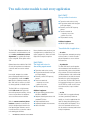
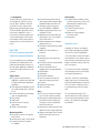
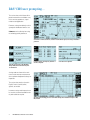
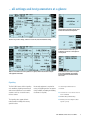
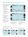
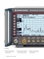
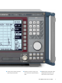
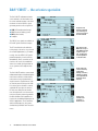
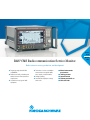
Version
05.00
¸CMS Radiocommunication Service Monitor
Radio testers for service, production, and development
◆ Frequency range from 0.4 MHz
to 1000 MHz
◆ Radio tester family incending two
models to cover all measurement
requirements
◆ Suitable for every type of radio
equipment
◆ Transmitter, receiver, and duplex
measurements on mobile radios,
base stations, and RF modules
◆ Analog signaling
◆ Simultaneous display of settings
and results
◆ Manual and automatic
measurements
◆ Tracking generator
◆ Spectrum monitor
◆ Stationary and mobile use
◆ Cable fault finder
October
2007
Two radio tester models to suit every application
¸CMS57
The specialist for avionics
◆ Transmitter and receiver testing
◆ RF spectrum monitor with zero-span
to full-span display
◆ Extremely sensitive RF frequency
counter
◆ Transient recorder for
– frequency versus time
– power versus time
◆ Fully automatic testing
Additional equipment
◆ VOR/ILS signal generator
Versatile fields of application ...
The ¸CMS radiocommunication service monitor is the ideal radio tester for
use in service, maintenance, and test
departments. It is suitable for all transceivers using AM, FM or, jM as well as
SSB.
Optional extensions enable the ¸CMS
to satisfy all requirements of radio measurements and even to cover related
fields.
Low weight, compact size, and low
power consumption make this instrument particularly suitable for mobile
use. Whether stationary or mobile, the
¸CMS with its extensive test facilities always provides a valuable service.
The ¸CMS uses a high-contrast,
backlit LCD screen with high resolution and is operated via softkeys. A clear
menu structure allows fast and direct
access to all measurement facilities.
With the autorun control and printer
interface, automatic test routines can
easily be configured and stored via the
front-panel keypad. Tolerances can be
inserted into these test routines to determine and log pass/fail limits.
¸CMS Radiocommunication Service Monitor
Battery-backed memory cards are used
as program and test report library. Test
reports, program lists, and screen hardcopies can be output on a printer.
¸CMS54
The high-end tester for
demanding requirements
◆ Transmitter and receiver testing
◆ RF spectrum monitor with zero-span
to full-span display
◆ Extremely sensitive RF frequency
counter
◆ Transient recorder for
– frequency versus time
– power versus time
◆ Fully automatic testing
Additional equipment
◆ Full-span tracking generator from
0.4 MHz to 1000 MHz
◆ Adjacent-channel power meter with
standard ETSI filters
◆ Duplex modulation meter
◆ Automatic harmonic measurements
◆ Cable fault finder
... in service
Ease of operation, automatic presettings
and test routines, as well as clear display of all parameters ensure efficient
measurements.
... in production
The ¸CMS can be used in production environments both for module testing and for final system testing without
any restriction. The built-in autorun control allows modules to be tested and adjusted without the need for an external
controller, the results being logged at
the same time. The ¸CMS can also
be integrated into larger test systems via
the IEC/IEEE bus, which results in short
measurement times in pre- and final
testing.
... on-site
The ¸CMS is a rugged and handy
unit that is particularly suitable for
mobile use. It can be supplied from the
local DC voltage (long operating times
due to low power consumption). The results of the automatic transceiver test
can be stored on a memory card for later
analysis and printout.
... in development
The ¸CMS offers great benefits to
the development engineer: In a minimum of space it combines RF and AF
generators as well as analyzers with
high accuracy and wide dynamic range.
The ¸CMS54 in particular features
measurement capabilities, such as
measurement of frequency/power transients of mobile phones, base stations
or RF modules, which usually require a
comprehensive set of measuring instruments.
¸CMS
A test set replacing many individual measuring instruments
Due to the comprehensive standard configuration of the individual ¸CMS
models and the optional extensions tailored to specific applications, additional
external measuring instruments are not
required.
Signal sources
◆ RF synthesizer from 0.4 MHz to
1000 MHz, resolution 10 Hz, with AM,
FM, jM, and multitone modulation
capabilities
◆ Two independent modulation generators, 20 Hz to 30 kHz each, resolution
0.1 Hz
◆ Selective-call coder for all standards
(also user-programmable)
◆ CDCSS coder
◆ DTMF coder
◆ 10 MHz reference frequency
input/output
◆ VOR/ILS signal generator
Measuring facilities
◆ RF frequency counter, RF frequencyoffset counter
◆ RF power meter from 1 mW to 100 W
◆ Selective RF power meter down
to –100 dBm
◆ RF spectrum monitor with wide dynamic range and filters that also allow
modulation analysis (AM, FM, SSB)
◆ Tracking generator in frequency
range from 400 kHz to 1000 MHz
◆ Adjacent-channel power meter with
standard ETSI filters
◆ Modulation meter for AM, FM, and
jM; detectors: +PK, –PK, PK HOLD,
±PK/2, RMS, RMS √2
◆ Duplex modulation meter for duplex
spacings of any size
◆ AF voltmeter with peak and true RMS
weighting
◆ SINAD meter with variable test
frequency
◆ S/N meter
◆ Distortion meter with variable test
frequency
◆ AF frequency counter with period and
gate-time counting
◆ Selective-call decoder for all
standards (also user-programmable)
◆ DTMF decoder
◆ Oscilloscope
◆ DC ammeter/voltmeter
◆ Transient recorder for analysis of
power and frequency transients
◆ SSB menus
◆ Harmonic measurements
◆ Cable fault finder
Filters
◆ CCITT or C-message filter for weighting in line with relevant standards
◆ Continuously tunable bandpass filter
from 50 Hz to 5 kHz with high skirt
selectivity for selective modulation
and AF measurements
◆ Continuously tunable notch filter from
100 Hz to 5 kHz for signal suppression
◆ Highpass and lowpass filters for band
limiting and measurement of subaudio tones
Other facilities
◆ Second RF input with high sensitivity
for off-air measurements, can be used
independently for module testing
◆ Connector for battery
◆ 13 dBm RF output for off-air
measurements
◆ Memory for storing complete
instrument setups
◆ Carrying bag
Automatic tests
Automatic test routines are indispensable for high throughput and reproducible results in service and production:
In the learn mode, the ¸CMS radiocommunication service monitor stores all
manual settings and measurements and
produces from them ready-to-start automatic test routines.
The user does not require any programming knowledge or have to learn equipment-specific command sets.
Tolerances, comments, and conditions
(loops, jumps, queries, and control commands) can additionally be inserted into
these test routines. Programs can also
be activated directly from the memory
card.
The test report format may be userspecified and can be clearly structured
by transferring control characters to the
printer, such as blank line, paragraph,
and boldface.
¸CMS Radiocommunication Service Monitor
¸CMS user prompting ...
The user interface, which shows all important measurements and allows entry
of the necessary parameters, is optimized for each application.
Erroneous settings immediately result in
a prompt for clarification from the user.
Submenus can be called up for setting
or evaluating specific parameters.
Transmitter test: RF measurements, evaluation of demodulated signals, and setting of modulation
generators
Contents, duration, and frequency deviation of
selective call signals
Zoom function for alignment
Using the insertion units of the ¸NAS
family, VSWR, forward and reflected power
can be indicated
Settings made are shown in the main
menu so that erroneous measurements
due to unknown background settings are
impossible.
The user interface may be selected in
English, French, German, Italian,
Spanish, or Swedish.
Instrument settings and frequencies can
be saved in an internal nonvolatile memory and recalled as required.
Spectrum monitor/tracking generator: 150 Hz filter allowing direct modulation analysis for AM,
FM, and SSB
¸CMS Radiocommunication Service Monitor
... all settings and test parameters at a glance
Channel numbers and duplex spacing can be
defined and used instead of frequencies
Receiver test: generator settings, evaluation of receiver AF, and carrier modulation setting
External modulation can be used, e.g. for
modulating several tones or data signals for
various systems
Duplex test: transmitter and receiver parameters at a glance; efficient measurements on duplex
radio equipment and modules
Semi-automatic search routines for squelch
level, receiver bandwidth, and sensitivity
perform elaborate measurements within a
few seconds
Signaling
The ¸CMS features built-in signaling
units combining signaling measurements
and receiver/transmitter tests on mobile
stations as well as, to a certain extent,
on base stations.
No external equipment is required for
testing. All signaling routines are permanently available (no loading or reloading
of software is required).
The following standards can be
simulated:
◆ Selective call in line with all international standards
◆ DTMF coding and decoding
The signaling units support all main
radio networks including their countryspecific versions.
◆ CDCSS (continuous digital coded
squelch system)
¸CMS Radiocommunication Service Monitor
¸CMS54 – the radio tester for the high-end service
For all fields of radiocommunications
◆ Base-station testing and monitoring
◆ Development of RF modules for any
application such as
– radio remote control
– cordless telephones
– door-closing systems
◆ Production and installation of systems with high or low transmitter
power, such as
– high-power transmitters
– radio telephones, mobile phones
◆ Duplex modulation meter with any
frequency offset
◆ Direct measurement of transmitter
harmonic suppression
Full-span spectrum monitor
◆ Full-span spectrum display from
10 MHz to 1000 MHz
◆ Display range 80 dB
◆ Analysis bandwidths from 150 Hz
(modulation spectra AM/FM/SSB)
to 3 MHz
◆ Sensitivity down to –110 dBm
◆ Markers for synthesizer-accurate
frequency measurements and
selective level measurements
◆ Reference marker
◆ Storage of spectrum displays and
demodulation of displayed spectral
lines (FREEZE & LISTEN)
◆ Quick mode for fast alignment of
RF components
◆ Built-in tracking generator with
selectable level and frequency offset;
for measurements on filters, modules,
and antenna systems
◆ Cable fault finder
Transient frequency and power measurements
Display of frequency transients when
switching transceivers on/off or when
changing channel
¸CMS Radiocommunication Service Monitor
Combined display of power and frequency
transients
Measurement of power levels upon
switching a transmitter on and off or of
power ramps (data transmission system)
Adjacent-channel power measurement
Adjacent-channel power can be measured directly without
external filters. The filters required in line with ETSI recommendations are integrated in the ¸CMS.
Harmonic measurements
Harmonics in the range up to 1 GHz are measured at a keystroke and displayed in digital and analog form.
Transient recorder (also for the ¸CMS57)
Measurement of power and frequency as a function of time with graphical
display and selectable zoom
Time scale
50 µs/div to 1 s/div,
max. recording time 40 s
Frequency transients
RF measurement range
1 MHz to 1000 MHz
FM deviation measurement range
0 kHz to ±100 kHz
Scaling
0.5 kHz to 50 kHz/div
Triggering
internal, automatic
(frequency changes >8 kHz)
Power transients
Additional data of the¸CMS54
Specifications of Base Unit (pages 13 and 14)
are fully applicable.
RF measurement range
1 MHz to 1000 MHz
Display dynamic range
60 dB (for 47 dBm at input 1)
Scaling
2/5/10/20 dB/div
Triggering
internal, automatic (power 10 %)
Adjacent-channel power measurements
(with the ¸CMS-B9 also for the ¸CMS57)
Filter ETSI recommendation
RF spectrum monitor (also for ¸CMS57)
Frequency range
1 MHz to 1000 MHz
Span
0 Hz (zero span) to 50 MHz; full span for
frequency range 10 MHz to 1000 MHz
Reference level
+47 dB to –47 dBm (input 1)
Sensitivity
<–110 dBm (for resolution filter
≤6 kHz and reference level
≤–37 dBm at input 2, f ≥ 10 MHz)
Display dynamic range
>65 dB (for reference level
>–7 dBm at input 1)
Scaling
2/5/10 dB/div
Display range
≤80 dB
Resolution filter (3 dB bandwidth)
150 Hz (for modulation analysis),
6/16/50/300 kHz/1/3 MHz (for full
span), coupled to span
Error
<3 dB + resolution
Resolution
0.4 dB
Channel spacings
10/12.5/20/25 kHz and
user selectable up to 1 MHz
Frequency transients
Dynamic range (CW, FM)
1 MHz to 1000 MHz
70 dB
69 dB
68 dB
66 dB
25 kHz
20 kHz
12.5 kHz
10 kHz
Harmonic measurements (with the ¸CMS-B9 also for the ¸CMS57)
Display of 1st to 4th harmonic
Max. harmonic frequency
1000 MHz
Dynamic range
>60 dB
>90 dB in frequency range
26.965 MHz to 27.405 MHz (CB radio)
RF frequency counter (also for the ¸CMS57)
Tracking generator (with ¸CMS-B9 also for the ¸CMS57)
Frequency range
400 kHz to 1000 MHz
Reference level
–27 dBm to –67 dBm
Display dynamic range
50 dB (1 MHz to 500 MHz)
45 dB (500 MHz to 1000 MHz)
Span
0 (zero span) to full span
Filters (3-dB bandwidth)
150 Hz, 6/16/50/300 kHz,
1/3 MHz (coupled to span)
Error
<3 dB (relative measurement <0.5 dB)
Resolution
0.4 dB
Output level
0 dBm to –128 dBm
Frequency offset
0 Hz to ±999 MHz (depending on span and
center frequency)
Frequency range
0.5 MHz to 1000 MHz
(usable from 100 kHz, IF narrow)
Input level range (CW, FM)
Input 1
Input 2
0 dBm to +47 dBm
–40 dBm to +7 dBm
Transmitter measurement, 2nd RF input (also for the ¸CMS57)
Additional internal, switch-selectable 0/24 dB attenuator pad for measurements
with higher levels at input 2
¸CMS Radiocommunication Service Monitor
Unit in original size
◆ All functions are clearly displayed;
16 softkeys allow direct access to
individual parameters
¸CMS Radiocommunication Service Monitor
◆ The large, backlit LCD screen provides
clear and simultaneous readout of all
test results, entries, and functions
◆ Hardcopy of screen display, entry of
tolerance and reference values are
made at a keystroke
◆ Settings can be varied in selectable
steps using the rotary knob
◆ Programs, instrument settings, and
test results can be stored on memory
cards
◆ Additional inputs and outputs allow
independent and versatile use of
signal sources and test facilities
¸CMS Radiocommunication Service Monitor
¸CMS57 – the avionics specialist
The ¸CMS57 radiocommunication
service monitor is the ideal radio tester
for service and maintenance in the field
of avionics. A built-in VOR/ILS signal
generator generates all test signals for
◆
◆
◆
◆
VOR (VHF omnidirectional range)
ILS (instrument landing system)
MB (marker beacon)
Autopilot
Frequencies and
deviations adjustable
over a wide range allow receiver testing in
line with standards
The VOR/ILS test signals are available as
RF and AF signals at different outputs.
The RF is not limited to the defined receiving ranges, but can be user-selected
for versatile applications (e.g. IF module
testing). Since the VOR/ILS AF signal is
provided separately, it can be fed into
demodulators, filters, or rectifiers of the
receiver or be used as the modulation
source of a second signal generator for
use as a jammer in the adjacent channels.
The ¸CMS57 combines conventional
radiocommunication and radionavigation
measurement facilities so that avionics
measurements can be performed by a
single instrument. Typical features such
as selectivity and sensitivity of the VOR/
ILS receiver can be checked. A second,
switchable RF input plus the selective
RF level meter and spectrum monitor
meet all requirements even for measurements on frequency-converting modules.
Parallel utilization of all capabilities offered results in additional advantages for
VOR/ILS applications. The AF voltmeter
and the oscilloscope are, for instance,
simultaneously available for AF measurements.
10
¸CMS Radiocommunication Service Monitor
Fine variation of the
DDM value in steps of
0.001 DDM for ILS and
of phase in steps of
0.01° for VOR ensure
accurate adjustment
of onboard monitor
The AF oscilloscope
can be used in all operating modes,
allowing, for instance,
simultaneous display
of the signal demodulated by the device
under test
A menu is also
available for the
generation of
marker beacons
Specific data of the ¸CMS57
VOR/ILS generator (specifications of base unit, pages 13 and 14, are fully applicable.)
The operating concept of the ¸CMS57
is designed in such a way that only a
few settings are required for testing all
characteristics of VOR/ILS receivers.
Signal parameters are defined either by
◆ direct keyboard entry
◆ fine variation via rotary knob
or
Phase RF output
Phase AF output
9960 Hz carrier
Modulation frequency
Amplitude modulation
–128 dBm to –9 dBm
– 85 dBm to –45 dBm
FM deviation
30 Hz VAR
Modulation frequency
Amplitude modulation
–128 dBm to –9 dBm
– 85 dBm to –45 dBm
◆ recall of preset standard
RF frequencies
◆ fixed coupling of ILS glideslope and
ILS localizer frequencies in line with
the specification
◆ recall of preset test parameters such
as phase or DDM (difference in depth
of modulation)
1020 Hz AUX
Modulation frequency
Amplitude modulation
By varying all test parameters an
in-depth analysis of all functions is
possible. In addition, a fast functional
test may be carried out by simply
recalling the standard settings in line
with ARINC 578, 579.
Small size, low weight, and battery
operation enable the ¸CMS57 to be
used in the cockpit or outside the aircraft
for fast go/nogo testing based on off-air
measurements (RAMP test).
Range
Resolution Error
0 ° to 360 °
0 ° to 360 °
0.01 °
0.01 °
typ. 0.05 °
≤0.04 °
0.1 % AM
0.1 % AM
1 Hz
typ. <2 % for 30 % AM
<2 % for 30 % AM
≤1 Hz
0 % to 100 %
0 % to 100 %
0.1 % AM
0.1 % AM
typ. <2 % for 30 % AM
<2 % for 30 % AM
50 Hz to 20 kHz
0 % to 100 %
0.1 % AM
≤3 %, for 1020 Hz and
10 % to 20 % AM
VOR
7.9 kHz to 12 kHz
0 % to 100 %
0 % to 100 %
384 Hz to 576 Hz
24 Hz to 36 Hz
ILS
≤1 °
90 Hz and 150 Hz phase
0 ° to180 °, referred to 150 Hz 0.01°
90 Hz tone
Modulation frequency
72 Hz to 108 Hz
150 Hz tone
Modulation frequency
120 Hz to 180 Hz
1020 Hz tone (AUX)
Modulation frequency
Amplitude modulation
50 Hz to 20 kHz
0 % to 100 %
0.1 % AM
≤3 %, for 1020 Hz and
10 % to 20 % AM
0 % to 50 %
0 % to 50 %
0.1 % AM
0.1 % AM
typ. <2 % for 20 % AM
<2 % for 20 % AM
ILS localizer
Amplitude modulation
–128 dBm to –9 dBm
– 85 dBm to –45 dBm
DDM1) RF output
±0 to 0.4 DDM for 20 % AM
On-course error, –128 dBm to –9 dBm
Off-course error, –128 dBm to –9 dBm
0.001 DDM
DDM AF output
±0 to 0.4 DDM for 20 % AM
0.001 DDM ≤3 % + 0.0002 DDM
for |DDM| ≤0.4,
AF level 0.5 V to 5 V
0 % to 50 %
0 % to 50 %
0.1 % AM
0.1 % AM
<0.0004 DDM
<2 % + 0.0004 DDM
for |DDM| ≤0.2
ILS glidescope
Amplitude modulation
–128 dBm to –9 dBm
– 85 dBm to –45 dBm
typ. <2 % for 40 % AM
<2 % for 40 % AM
DDM RF output
±0 to 0.8 DDM for 40 % AM
On-course error, –128 dBm to –9 dBm
Off-course error, –128 dBm to –9 dBm
0.001 DDM
DDM AF output
0.001 DDM ≤3 % + 0.002 DDM
for |DDM| ≤0.4,
AF level 0.5 V to 5 V
±0 to 0.8 DDM for 40 % AM
<0.001 DDM
<2 % + 0.001 DDM
for |DDM| ≤0.4
Marker beacon (MB)
Difference in Depth of Modulation; describes the
1)
modulation depth difference between the 90 Hz and the
150 Hz tone; |DDM| = |(90 Hz modulation in % - 150 Hz
modulation in %)|/100 %.
Modulation frequency
400 / 1300 / 3000 Hz
Amplitude modulation
0 % to 100 %
0.1 % AM
≤5 % for 95 % AM
1020 Hz tone (AUX)
Modulation frequency
Amplitude modulation
50 Hz to 20 kHz
0 % to 100 %
0.1 % AM
same as base unit
¸CMS Radiocommunication Service Monitor
11
Options and their applications
Extensions for base unit
Option
Order No.
Specifications
OCXO Reference Oscillator
For long-term stability
¸CMS-B1
0840.9406.02
see time base
Aging2 × 10–7/year
OCXO Reference Oscillator
For extremely high long-term stability
¸CMS-B2
1001.6809.02
Specs same as ¸CMS-B1,
except for aging
≤1× 10⁻⁷/year
0840.9506.021)
For specs see base unit, specs for ACP meter and harmonic
measurements on page 7
¸CMS-B9
Duplex Modulation Meter
Allows operation of RF frequenzy counter and modulation meter independent of RF signal generator (twopart measurements, also on frequency-converting
modules); provides tracking generator, cable fault
finder, adjacent-channel power meter, harmonic
measurements
TTL levels, Zout ≈ 50 W,
f = 10 MHz
level >1.5 V (Vpp), Zin ≈ 50 W,
f = 10 MHz ±500 Hz
10 MHz Reference Frequency Input/Output
External synchronization for measuring systems ¸CMS-B22
1001.6750.02
Output Input
Additional RF Input/Output
Two-signal measurements and connection of further
measuring instruments
¸CMS-B31
1001.7005.02
Maximum input power20 mW
Attenuation betw. RFin and RFout32 dB
Measurement sensivity at input 1 for RF counter/transient recorder and demodulation reduced by 6 dB
100 W RF Power Meter
Measurement of high RF input power
¸CMS-B32
1001.7905.02
Max. input power: 100 W for 3 min, then 10 min power off
Continuous power: 80 W, max. output level and measurement
sensitivity at input 1 reduced by 3 dB; additional error ≤0.2 dB
(P >40 mW, AM = 0 %)
13 dBm Output
¸CMS-B34
1032.1350.02
Additional power output for off-air measurements
Protection for Input 2
¸CMS-B60
1075.5006.02
BNC connector with exchangeable fuse
¸CMS-B5
0841.0502.10
¸CMS-B55
1032.0790.02
Specifications
Optional control interfaces2)
Order No.
DTMF Decoder
•
•
CCITT Filter
•
•
Centronics Interface
•
•
Direct printer connection
Relays
8
—
Switching relays with max. 1 W switching power,
Vmax = 30 V, Imax = 0.1 A
TTL Input/Output
12
—
Outputs: 25 mA driver power
Decoding of DTMF dual tones and VDEW direct dialing
Extensions in conjunction with control interfaces
Option
Order No.
Specifications
ATIS Coder/Decoder
For ¸CMS-B5
¸CMS-B27
1032.1250.02
CDSS Decoder
For ¸CMS-B5
¸CMS-B27
with ¸CMS-B33
Coder – entry of 10-digit ATIS code
– sending of ATIS message
Decoder – decoding and display of 10-digit ATIS code
Decoding of 3-digit mobile phone code number, measurement of
data deviation; CDCSS coder fitted as standard in base unit
1032.0290.02
fcutoff = 200 Hz, attenuation >50 dB for frequencies above 300 Hz
1065.4907.02
Connection of ¸NAS-Z1/ -Z3/ -Z5/ -Z6/ -Z7 insertion units with
direct reading of VSWR as well as forward and reflected power
¸CMS-B33
300 Hz Lowpass Filter
For ¸CMS-B5/-B55; fast frequency and deviation
measurement of subaudio tones with simultaneous
audio modulation
Adapter for VSWR Measurements
In conjunction with ¸CMS-B5
¸CMS-Z373)
Option is already included in ¸CMS54.
Choice of one option.
3)
¸CMS-B5 required for ¸NAS-Z1/-Z3/-Z5/-Z6/-Z7 insertion units.
1)
2)
12
¸CMS Radiocommunication Service Monitor
Specifications of the base unit
Time base
Standard
Temperature effect 0 ° to 35 °C
Aging
¸CMS-B1 and -B2 options
Temperature effect 0 ° to +50 °C
Aging
Warmup time (+25 °C)
Modulation modes
≤1 × 10
≤1 × 10⁻⁷/day
≤1 × 10⁻⁶ /month
≤2 × 10⁻⁶ /year
AF voltmeter
≤1 × 10⁻⁷
≤5 × 10⁻⁹/day after 30 days of operation
≤2 × 10⁻⁷/year (¸CMS-B2: ≤1 × 10⁻⁷)
approx. 10 min
Frequency range
50 Hz to 20 kHz
Measurement range
0.1 mV to 30 V
Resolution
100 µV, V < 10 mV; 1 %, V ≥ 10 mV
Error
<5 % + resolution
Input impedance
approx. 1 MΩ
2)
Distortion meter, SINAD meter,
see transmitter and receiver measurements
AF frequency counter
Receiver measurements
Signal generator
Frequency range
¸CMS54, ¸CMS 57
0.4 MHz to 1000 MHz
usable from 100 kHz
Frequency resolution
10 Hz
RF power meter
Frequency error
same as time base
Frequency range
1.5 MHz to 1000 MHz
Measurement range
5 mW to 50 W3) (100 W optionally)
Error (P > 20 mW, AM = 0 %,
Tambient = 0° C to 40° C)
≤0.45 dB of rdg + resolution
Level
FM, jM, CW
AM
Transmitter measurements
–134 dBm to 0 dBm
–134 dBm to –3 dBm (depending on
modulation depth)
Level resolution
0.1 dB
Fine variation of level
FM, jM, CW
AM
0 dB to –19.9 dB, non-interrupting
0 dB to –4.9 dB, non-interrupting
Resolution
1 mW, P < 100 mW; 1 %, P ≥ 100 mW
Selective level measurement
Level range
in frequency range 1 MHz to 1000 MHz
–60 dBm to +47 dBm without weighting
filter, –80 dBm to +47 dBm with 2 kHz
resonance filter
Level error
≤2 dB (for levels –128 dBm to –3 dBm,
f >1 MHz)1)
RF frequency counter
Harmonics
≤–25 dBc
Frequency range
0.5 MHz to 1000 MHz
Nonharmonics
≤–50 dBc
(>5 kHz from carrier, level –3 dBm)
Input level range
5 mW to 50 W3)
Resolution
10 Hz, 1 Hz
Residual AM (CCITT, RMS)
≤0.03 %
Error
same as time base + resolution
Frequency deviation meter
Residual FM (CCITT, RMS)
0.4 MHz to 250 MHz, 500 MHz ≤10 Hz
to 1000 MHz
250 MHz to 500 MHz
≤5 Hz
Phase noise
≤–110 dBc/Hz (20 kHz from carrier)
Modulation
Frequency range
0.4 MHz to 1000 MHz
AM modulation depth
Resolution
Mod. frequency range
0 % to 99 %
0.5 %
DC to 10 kHz, f < 8 MHz,
DC to 20 kHz, f ≥ 8 MHz
≤2 %, fAF = 1 kHz
≤5 % + resolution + residual AM,
fAF = 300 Hz to 3 kHz
Mod. distortion (m < 0.8)1)
Mod. error (m < 0.8)1)
FM deviation Resolution
Mod. frequency range
Mod. distortion
Mod. error
jM deviation (internal)
Resolution
Mod. frequency range
Mod. distortion
Mod. error
internal (single-tone/two-tone),
external, internal + external
–6
Operating modes
+PK, –PK, ±PK/2, PK HOLD, RMS, RMS√2
Input level range
5 mW to 50 W3)
RF frequency range
1.5 MHz to 1000 MHz
Deviation measurement range
0 Hz to 100 kHz
AF frequency range
20 Hz to 20 kHz
(DC-coupled at demodulator output)
Resolution
1 Hz, Df < 1 kHz; 1 %, Df ≥ 1 kHz
Residual FM (CCITT, RMS)
0.4 MHz to 250 MHz,
500 MHz to 1000 MHz
250 MHz to 500 MHz
Error2)
≤10 Hz
≤5 Hz
≤5 % + resolution + residual FM
0 Hz to 100 kHz
(fRF = 250 MHz to 500 MHz, 0 kHz to 50 kHz)
1 Hz, Df < 100 Hz; 1% Df ≥ 100 Hz
20 Hz to 20 kHz (suitable for POCSAG)
≤1 % (fAF = 1 kHz; Dϕ = 10 kHz)
≤5 % + resolution + residual ϕM
0 rad to 10 rad
(fRF = 250 MHz to 500 MHz, 0 rad to 5 rad)
1 mrad, Dj < 0.1 rad; 1 %, Dj ≥ 0.1 rad
100 Hz to 6 kHz
≤1 % (fAF = 1 kHz; Dj = 10 rad)
≤5 % + resolution + residual jM
Fine variation of level 0 dB.
Without weighting filters.
3)
Input level max. 30 W for any RF output level, max. 50 W for RF output level <–26 dBm.
1)
2)
¸CMS Radiocommunication Service Monitor
13
Transmitter and receiver measurements
Modulation generator I and II
Phase deviation meter
Operating modes
+PK, –PK, ±PK/2, RMS, RMS√2
Frequency range
20 Hz to 30 kHz (usable from 1 Hz)
Input level range
5 mW to 50 W
Frequency resolution
0.1 Hz
RF frequency range
1.5 MHz to 1000 MHz
Error
same as time base + ½ resolution
Phase deviation measurement
range
0.001 rad to 5 rad
Output level range
AF frequency range
300 Hz to 6 kHz
10 µV to 5 V, fAF = 20 Hz to 20 kHz
10 µV to 2.5 V, fAF = 20 Hz to 30 kHz
Resolution
Resolution
0.001 rad, Dj ≤ 0.1 rad; 1 %, Dj > 0.1 rad
10 µV, V < 1 mV
1 %, V ≥ 1 mV
Error 2)
same as frequency deviation meter +
2 % frequency response
Error
≤5 %, V ≥1 mV
Output impedance
≤4 W
Max. output current (peak)
20 mA
Distortion
≤0.5 %, fAF = 20 Hz to 20 kHz
1)
AM depth meter
Operating modes
+PK, –PK, ±PK/2, RMS, RMS√2
Input level range
20 mW to 50 W1) (PEP)
RF frequency range
1.5 MHz to 1000 MHz
AM depth measurement range
0.01 % to 99 %
AF frequency range
50 Hz to 20 kHz
Resolution
0.01 %, m < 0.1, 0.1 %; m ≥ 0.1
Residual AM (CCITT, RMS)
≤0.03 %
Error (m ≤ 0.8) 2)
≤7 % + resolution + residual AM
(fAF = 0.3 kHz to 3 kHz)
Distortion meter, SINAD meter,
AF frequency counter
see transmitter and receiver measurements
Distortion meter
Frequency
100 Hz to 5 kHz (in 10 Hz steps)
Input level range
100 mV to 30 V
Measurement range
0.1 % to 50 %
Resolution
0.1 %
Inherent distortion
≤0.5 %
Weighting bandwidth
≤12 kHz
Error
≤5 % + inherent distortion
SINAD meter
Transmitter measurement at 2nd RF input
Measurement of RF frequency, modulation (AM, FM, jM), modulation frequency, and RF spectrum (level) of small RF signals, e.g. in off-air or module
measurements, for input levels from approximately
RF frequency counter
¸CMS54, ¸CMS57
30 µV (select. counter with presetting)
–40 dBm to +7 dBm (without presetting)
Modulation meter
5 µV (IF narrow)
1 µV (IF narrow, select. measurement)
Selective level measurement
–75 dBm to –35 dBm without weighting
filter, –100 dBm to –35 dBm with
2 kHz resonance filter
Frequency
100 Hz to 5 kHz
Measurement range
1 dB to 46 dB
Input level range
100 mV to 30 V
Resolution
0.1 dB
Weighting bandwidth
≤12 kHz
Error
≤1 dB + inherent distortion
AF frequency counter
Operating modes
demodulation, AF, beat (frequency offset),
external
Frequency range
20 Hz to 500 kHz (superimposed RF)
Input level range
10 mV to 30 V, f < 20 kHz
Resolution
1 Hz/0.1 Hz
Error
same as time base + resolution
Oscilloscope
Bandwidth
1) Input level max. 30 W for any RF output level, max. 50 W for RF output level <–26 dBm.
2) Without weighting filters.
14
¸CMS Radiocommunication Service Monitor
DC: DC to 20 kHz
AC: 10 Hz to 20 kHz
Horizontal deflection
20 ms/div to 0.1 ms/div
Vertical deflection
scaled in kHz (FM), rad (jM),
% (AM), mV/V (AF)
Input level range
0 V to 40 V (Vp)
Input impedance
approx. 1 MW
Ordering information
Radiocommunication Service Monitor
AF filters
Highpass
fcutoff = 300 Hz, attenuation
at 200 Hz typ. 40 dB
Lowpass
fcutoff = 3.4 kHz, attenuation
at 10 kHz typ. 40 dB
Bandpass broadband
narrowband
highpass + lowpass
50 Hz to 5 kHz in 10 Hz steps,
attenuation typ. 40 dB for 0.8f and 1.2f
Notch filter
100 Hz to 5 kHz in 10 Hz steps,
attenuation typ. 40 dB
CCITT filter
see ¸CMS-B5 or ¸CMS-B55 option
Selective call coder/decoder
Tone sequences
ZVEI1/ZVEI2/CCIR/EIA/EEA/EURO/NATEL/
CCITT/VDEW/DTMF/user-defined sequences
(for DTMF decoding see control interface)
CDCSS coder
entry of 3-digit code number of mobile radio,
setting of times for turn-off code and
RF level drop, setting of data deviation
Audio monitor (loudspeaker)
demodulated signal, AF signal,
beat (frequency offset)
¸CMS54
0840.0009.54
¸CMS57
0840.0009.57
Accessories supplied
power cable, spare fuses, manual
Options
see page 12
Recommended extras
Memory Card 128 kbyte
¸CMS-Z2
0841.1509.02
Battery Connector
¸CMS-Z7
0841.1350.02
Carrying Bag
¸CMS-Z40
1065.5603.02
Battery Pack with Charger2)
¸CMS-Z41
1065.5703.02
Printer Cable
¸CM-Z5
0835.6919.02
19“ Adapter
¸ZZA-99
Service Manual
0839.5775.00
0840.8616.24
General data
Operating temperature range
0 °C to +50 °C
Storage temperature range
–40 °C to +70 °C
Environmental resistance
Temperature
Climatic (damp heat)
Mechanical resistance
Sinusoidal vibration
Standards complied with
Random vibration
Shock
Standards complied with
in line with EN 60068-2-1 and EN 60068-2-2
+25 °C/+40 °C cyclically at 95 % rel.
humidity; with EN 60068-2-30
5 Hz to 150 Hz, max. 2 g at 55 Hz,
0.5 g at 55 Hz to 150 Hz
EN 60068-2-6 and EN 61010-1 as well as
MIL-T-28800D class 5
10 Hz to 300 Hz, acceleration 1.2 g rms
40 g shock spectrum
MIL-STD-810C and MIL-T-28800D
class 3 and 5
EMC
in line with EMC directive of EU
(2004/108/EC) applied standard EN61326
(immunity for industrial environment;
class A emissions)1)
Safety
in line with EN 61010-1
Power supply
(100/120/220/240) V AC ±10 %,
47 Hz to 420 Hz or 11.5 V to 30 V DC (50 W)
Dimensions (W × H × D)
320 mm × 175 mm × 375 mm
(12.6 in × 6.9 in × 14.8 in)
Screen size
approx. 210 mm × 100 mm (9”)
approx. 8.3 in × 3.9 in (9”)
Weight
approx. 13 kg (28.6 lb) without options
approx. 15 kg (33 lb) with options
The instrument complies with the emission requirements stipulated by EN 55011 class A. This means that the instrument is suitable for use in industrial environments. In line with
EN 61000-6-4, operation is not covered in residential, commercial, and business areas nor in small-size companies. Thus, the instrument must not be operated in residential, commercial,
and business areas nor in small-size companies, unless additional measures are taken to ensure that EN 61000-6-3 is met.
2)
Battery operation approx.: 1 hour (+25 °C), weight: 4 kg (8.8 lb), Dimensions (W × H × D) 85 mm × 175 mm × 375 mm (3.35 in × 6.89 in × 14.76 in).
1)
¸CMS Radiocommunication Service Monitor
15
Certified Environmental System
ISO 9001
ISO 14001
DQS REG. NO 1954 QM
DQS REG. NO 1954 UM
More information at
www.rohde-schwarz.com
(search terms: CMS54, CMS57)
www.rohde-schwarz.com
Europe: +49 1805 12 4242, [email protected]
Americas: +1-888-837-8772, [email protected]
Asia: +65 65 130 488, [email protected]
¸ is a registered trademark of Rohde & Schwarz GmbH & Co. KG · Trade names are trademarks of the owners · Printed in Germany (sv)
PD 5213.8996.32 · Version 05.00 · October 2007 · ¸CMS · Data without tolerance limits is not binding · Subject to change
Certified Quality System