1
Important
Please read PRECAUTIONS and this User’s Manual carefully to
familiarize yourself with safe and effective usage procedures. Please
retain this manual for future reference.
Copyright© 2007 Tech Source, Inc.
Copyright© 2007 EIZO NANAO CORPORATION
No part of this manual may be reproduced, stored in a retrieval system, or transmitted, in any form or
by any means, electronic, mechanical, or otherwise, without the prior written permission of Tech
Source, Inc. and EIZO NANAO CORPORATION.
Tech Source, Inc. and EIZO NANAO CORPORATION are under no obligation to hold any submitted
material or information confidential unless prior arrangements are made pursuant to Tech Source, Inc.
and EIZO NANAO CORPORATION’s receipt of said information. Although every effort has been
made to ensure that this manual provides up-to-date information, please note that EIZO monitor
specifications are subject to change without notice.
DPMS is a trademark and VESA is a registered trademark of Video Electronic Standards Association.
Windows is a registered trademark of Microsoft Corporation.
Raptor is a trademark of Tech Source, Inc. and EIZO NANAO CORPORATION.
EIZO is a registered trademark of EIZO NANAO CORPORATION in Japan and other countries.
Product specification may vary with sales areas.
Confirm the specification in the manual written in language of the region of purchase.
Contents
1
1.1
1.2
1.3
1.4
1.5
Overview............................................................................................................................... 6
Layout of this Manual............................................................................................................. 7
Warnings and Safety Notes ................................................................................................... 8
Packaging .............................................................................................................................. 9
Instructions for Handling Components Susceptible to Electrostatic Shocks........................ 10
Cleaning............................................................................................................................... 10
2
2.1
2.2
2.2.1
2.2.2
2.2.3
2.3
2.3.1
2.3.2
2.3.3
2.3.4
2.3.5
2.3.6
2.4
General Installation ........................................................................................................... 11
Removal of Packaging and Checking of Component Parts................................................. 11
Installing the Monitor............................................................................................................ 12
Raptor SQ2801 Dimensions (Chassis version) ................................................................... 13
Raptor SQ2801 Dimensions (Desktop version)................................................................... 16
Raptor SQ2801 Dimensions (Panel mount version)............................................................ 19
Interfaces and Connector Assignment................................................................................. 22
Analog RGB – Interface....................................................................................................... 23
DVI-1 / DVI-2 Interface ........................................................................................................ 24
RS232-1 Interface................................................................................................................ 25
RS232-2 Interface................................................................................................................ 25
RS422 Interface................................................................................................................... 26
External OSD-Keyboard Interface ....................................................................................... 27
Electrical Installation ............................................................................................................ 27
3
3.1
3.2
3.2.1
3.2.2
3.2.2.1
3.2.2.2
3.2.2.3
3.2.2.4
3.2.2.5
3.2.2.6
3.2.2.7
3.2.2.8
3.2.2.9
3.3
3.3.1
3.3.2
3.4
Operation and Adjustment................................................................................................ 28
Function of OSD Keys and LED .......................................................................................... 28
OSD-Menu / Quick-OSD-Menu ........................................................................................... 29
Quick-OSD-Menu ................................................................................................................ 29
OSD-Menu........................................................................................................................... 30
OSD-Menu – Picture............................................................................................................ 30
OSD-Menu (Advanced) ....................................................................................................... 32
OSD-Menu - Options 1 ........................................................................................................ 33
OSD-Menu - Options 2 ........................................................................................................ 34
OSD-Menu - Options 3 ........................................................................................................ 36
OSD-Menu – Utilities ........................................................................................................... 37
OSD-Menu - Utilities / Installation RGB-Mode..................................................................... 38
OSD-Menu - Infos 1............................................................................................................. 39
OSD-Menu - Infos 2............................................................................................................. 40
Adjustment Analog Signal Source (DDM)............................................................................ 41
Adjustment Phase and Frequency....................................................................................... 41
Automatic Phase Adjustment............................................................................................... 42
Adjustment of Backlight Brightness / Automatic Backlight Control ...................................... 42
4
4.1
4.1.1
4.1.2
4.1.3
4.2
4.2.1
4.3
Serial Communication....................................................................................................... 43
Standard Protocol ................................................................................................................ 44
Data Packet Structure “Operation” ...................................................................................... 45
Data Packet Structure “Keyboard Simulation” ..................................................................... 46
Calculation of CRC - Check Sum ........................................................................................ 47
Simplified Protocol ............................................................................................................... 49
Data Packet Structure.......................................................................................................... 49
DDM-Protocol ...................................................................................................................... 52
4
Contents
5
5.1
5.2
5.3
5.4
5.5
5.6
5.7
5.8
5.9
5.10
Technical Data ................................................................................................................... 54
Display Module .................................................................................................................... 54
Power Supply....................................................................................................................... 54
Operating Conditions ........................................................................................................... 55
Protection............................................................................................................................. 55
Housing................................................................................................................................ 55
Input signal RGB analog...................................................................................................... 55
Standard ATC-Timing .......................................................................................................... 56
Input Signal DVI-1 / DVI-2 ................................................................................................... 56
Recommended DVI-Timing 2,048 x 2,048 Pixel.................................................................. 56
EU – Declaration of Conformity on EMC ............................................................................. 57
6
6.1
6.2
Part Numbers and Field Replaceable Units (FRUs)........................................................ 58
TSI ATC Visualization Kit..................................................................................................... 58
Raptor SQ2801 Field Replaceable components ................................................................. 58
Figures
Fig. 1:
Fig. 2:
Fig. 3:
Fig. 4:
Fig. 5:
Fig. 6:
Fig. 7:
Fig. 8:
Fig. 9:
Fig. 10:
Fig. 11:
Fig. 12:
Fig. 13:
Fig. 14:
Fig. 15:
Fig. 16:
Fig. 17:
Fig. 18:
Fig. 19:
Fig. 20:
Fig. 21:
Fig. 22:
Fig. 23:
Fig. 24:
Package of the chassis monitor ............................................................................................... 9
Package of the desktop monitor............................................................................................... 9
Raptor SQ2801 Dimensions (Chassis version); Front View .................................................. 13
Raptor SQ2801 Dimensions (Chassis version); Rear View ................................................... 14
Raptor SQ2801 Dimensions (Chassis version); Side View.................................................... 15
Raptor SQ2801 (Desktop Version); Front View ..................................................................... 16
Raptor SQ2801 Dimensions (Desktop version); Rear View................................................... 17
Raptor SQ2801 Dimensions (Desktop); Side View................................................................ 18
Raptor SQ2801 Dimensions (Panel mount); Front View........................................................ 19
Raptor SQ2801 Dimensions (Panel mount); Side View......................................................... 20
Raptor SQ2801 Dimensions (Panel mount); Back View ........................................................ 21
Location of Interface Connectors ........................................................................................... 22
Connector type: 5 x BNC socket ............................................................................................ 23
OSD keyboard and LED......................................................................................................... 28
Quick-OSD-Menu................................................................................................................... 29
OSD-Menu - Picture............................................................................................................... 30
OSD-Menu (advanced) .......................................................................................................... 32
OSD-Menu - Options 1........................................................................................................... 33
OSD-Menu - Options 2........................................................................................................... 34
OSD-Menu - Options 3........................................................................................................... 36
OSD-Menu – Utilities.............................................................................................................. 37
OSD-Menu - Utilities / Installation RGB-Mode ....................................................................... 38
OSD-Menu – Infos 1 .............................................................................................................. 39
OSD-Menu – Infos 2 .............................................................................................................. 40
Figures
5
1
Overview
The TFT Monitor Raptor SQ2801 was developed to meet the very demanding requirements in the Air
Traffic Management where system availability and reliability is crucial. Ergonomic criteria have been
addressed to ensure high acceptance from the operators.
Reduced depth and lower weight compared to CRT monitors allow easy installation into workstation
consoles of air traffic control rooms. Considerably lower power consumption and heat emissions are
some of the other advantages over CRT based units.
The TFT technology employed in this design is based on Sharp’s ASV technology and offers very
sharp, undistorted image, right up to the edges. Unlike the CRT counterpart, this technology does not
have problems such as convergence or effects from electro magnetic radiation.
The Raptor SQ2801 is a 28.05“ TFT module with native resolution of 2,048 x 2,048 pixel. Wide
viewing angle of 170° (horizontally and vertically), a contrast ratio of 1000 : 1 and maximum
brightness of 210 cd/m² enable very clear and sharp pictures with color depth of 16.7 million colors. It
is backward compatible with Sony’s DDM1 monitors.
The Raptor SQ2801 product has two dual link DVI-D (digital) inputs and one analog input. OSD (on
screen display) allows control of various configurable parameters such as brightness, contrast and
input switching. These parameters can also be controlled via RS-232 and RS-422 interfaces.
Remote control software is available from Tech Source.
Key Features:
• 28.05“ TFT LCD Display (square format)
Direct replacement for CRT monitors.
• High Resolution of 2,048 x 2,048 Pixel
For input signals with a resolution up to 2,048 x 2,048 pixel; even lower resolution pictures
(e.g. during installation or service) are displayed correctly.
• Excellent Optical Characteristics
Brightness 210 cd/m², Contrast 1000 : 1, Viewing Angle 170° (horizontally and vertically).
• Versatile and Flexible Implementation
The analog RGB interface and two dual link DVI-D interfaces enable integration into different
systems
• Automatic Frequency- and Phase Adjustment
The monitor adjusts itself to the applied input signal.
• Automatic Backlight Stabilization
The selected brightness of the backlight unit is readjusted automatically.
1 Sony DDM is a registered trademark of Sony Corporation
6
1 Overview
1.1
Layout of this Manual
This manual was created to assist system integrators and operators during installation and operation
of the LCD TFT Monitor Raptor SQ2801. The layout is intended to allow even inexperienced users to
install and set-up the monitor.
The manual is divided into following chapters:
Chapter 1
Introduction
Brief description of the Raptor SQ2801
Chapter 2
Installation
The chapter discusses the installation and the various interfaces available to the
monitor
Chapter 3
Operation
Operation and adjustment controls of the Raptor SQ2801
Chapter 4
Serial Communication
Transmission protocol for communication between a PC / Workstation and the monitor
via a serial interface
Chapter 5
Technical Data
Display module, power supply, environment and other data
Chapter 6
Part numbers and Field Replaceable Units
Part numbers for all field replaceable units are discussed, as well as the various
components of the TSI ATC visualization kit.
1 Overview
7
1.2
Warnings and Safety Notes
For information about warnings and safety notes, refer to PRECATUIONS supplied with this manual.
8
1 Overview
1.3
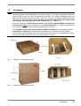
Packaging
NOTE To avoid permanent damage, great care should be taken to ensure that the monitor is
adequately packed and transported in the correct manner. The original packaging should be
retained and re-used for future transportation purposes. The original packaging has a red
label with two arrows and text “hier oben” (see Fig. 1 and Fig. 2), which indicates the correct
orientation of the package (i.e. when correctly packed this label should be aligned with
the top edge and front glass face of the monitor see Fig. 1 and Fig. 2.
Please note that the chassis mount version of the monitor (Raptor SQ2801 Chassis and
Panel mount) must only be transported in a horizontal position. (i.e. The front glass face of
the monitor should be facing up during transportation). See Fig. 1.
The desktop version of the monitor (Raptor SQ2801 Desktop) may be transported either
horizontally or vertically. If transported horizontally then, as in the case of the chassis
mount version, the front glass face of the monitor should be facing up. If transported vertically
then the red label should be at the top of the package. See Fig. 2
Fig. 1:
Package of the chassis monitor
Fig. 2:
Package of the desktop monitor
1 Overview
9
1.4
Instructions for Handling Components Susceptible to Electrostatic
Shocks
Most of the assemblies within the LCD monitor Raptor SQ2801 contain components which can be
permanently damaged or destroyed by electrostatic discharge. Such resulting damage may or may
not result in total failure of the components or modules affected.
The following precautions must be strictly observed when handling such assemblies (this work should
only be carried out by qualified service technicians):
• When handling electronic components, care should be taken to prevent electrostatic
discharge. Such discharge may occur when handling components or modules without
suitable precautions to ensure adequate grounding.
• This also applies to all (insulated) tools. They must also be discharged to earth at all times.
• When assemblies are removed or added to the system, the unit must always be switched off
and unplugged from the power supply.
• Vulnerable components should always be held by their edges. Avoid touching circuit paths
and contact pins.
1.5
Cleaning
Clean the monitor periodically to keep the monitor clean and extend its life.
Cabinet
Clean the cabinet with a soft cloth dampened with little mild detergent.
NOTE Never use any solvents or chemicals, such as thinner, benzene, wax, alcohol, and abrasive
cleaner, which may damage the cabinet or LCD panel.
LCD Panel
• Clean the LCD panel with a soft cloth such as cotton cloth or lens cleaning paper.
• Remove persistent stains gently with a cloth dampened with little water, and then clean the
LCD panel again with a dry cloth for better finishing.
TIPS Optional ScreenCleaner is recommended for cleaning the LCD panel surface.
10
1 Overview
2
General Installation
Preparation for installing the LCD monitor includes following steps:
• Removal of all packaging materials
• Checking of components for damage
• Comparison of components received with those listed on the delivery note
• Connection to the computer system and power supply
• System integration under consideration of technical and ergonomic aspects
2.1
Removal of Packaging and Checking of Component Parts
After unpacking all delivered components, they should be checked for completeness and for possible
shipping damage (visual inspection). If any parts are missing or damaged, please contact your local
dealer. Have your packing list number, serial number of the unit and a description of the problem
available when calling.
The original packaging should be kept for future shipping of the product.
2 General Installation
11
2.2
Installing the Monitor
The Raptor SQ2801 is currently offered in two versions - desktop version and chassis version. Both
these version are discussed in this section.
The desktop version is a “standalone” unit that can be placed on top of a desktop console. As for the
chassis version, it is easy to integrate it onto the rear of control panel or a console by using two
mounting brackets.
Please note the following for safe and proper operation:
Ambient Temperature
In order for the LCD monitor to maintain an optimum operating temperature while in use, air must be
allowed to circulate freely around the Raptor SQ2801 enclosure. This is especially important for the
rear of the unit. Convection current must be allowed to circulate around the enclosure.
Please bear in mind that increased temperatures may result in on-screen defects and significantly
reduced lifetime of the panel.
EMC – Radiation
The LCD monitor is a piece of equipment designed for integration into an industrial system. The
operator of the entire plant is responsible for maintaining electromagnetic compatibility according to
EMC laws.
Safety Aspects
All voltage and signal connections must adhere to legal requirements.
Ergonomics
The screen comes with anti-reflective glass. However, it should be installed/positioned properly to
allow easy viewing from all sides.
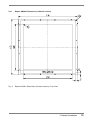
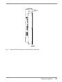
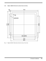
Mechanical Integration
The chassis version is secured into a system by 6 bolts (M6 x 10). These bolts can be used for
attaching mounting angles which allow mounting the monitor in a control panel or a console (see Fig.
4, Page 14). The dimensions in the drawings are all in mm.
12
2 General Installation
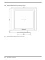
2.2.1
Raptor SQ2801 Dimensions (Chassis version)
Fig. 3:
Raptor SQ2801 Dimensions (Chassis version); Front View
2 General Installation
13
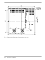
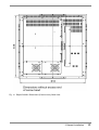
Fig. 4:
Raptor SQ2801 Dimensions (Chassis version); Rear View
14
2 General Installation
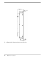
Fig. 5:
Raptor SQ2801 Dimensions (Chassis version); Side View
2 General Installation
15
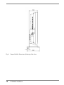
2.2.2
Raptor SQ2801 Dimensions (Desktop version)
Fig. 6:
Raptor SQ2801 (Desktop Version); Front View
16
2 General Installation
Fig. 7:
Raptor SQ2801 Dimensions (Desktop version); Rear View
2 General Installation
17
Fig. 8:
Raptor SQ2801 Dimensions (Desktop); Side View
18
2 General Installation
2.2.3
Raptor SQ2801 Dimensions (Panel mount version)
Fig. 9:
Raptor SQ2801 Dimensions (Panel mount); Front View
2 General Installation
19
Fig. 10: Raptor SQ2801 Dimensions (Panel mount); Side View
20
2 General Installation
Fig. 11: Raptor SQ2801 Dimensions (Panel mount); Back View
2 General Installation
21
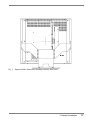
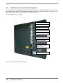
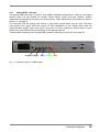
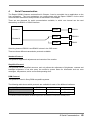
2.3
Interfaces and Connector Assignment
The monitor has been tested and pre-adjusted at the factory. For system installation, connect the unit
to the main power supply, serial interfaces and input sources. All input connectors are shown in the
figure below. All connections should adhere to EMC regulations.
Use cord grips to secure cables.
RS232-2
RS232-1
RS422
DVI-2
DVI-1
Analog R,G,B,H,V
External Keyboard
Main Power; Power
Switch; Fuse
Clip for Cord Grips
Fig. 12: Location of Interface Connectors
22
2 General Installation
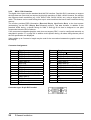
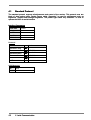
2.3.1
Analog RGB – Interface
The analog RGB input may be used for Sony DDM compatible configurations. However, the Raptor
SQ2801 panel can also handle all common VESA timings. When using this interface, specific
adjustments for phase and frequency may be necessary. These adjustments are explained in detail in
section 3.3 on page 41.
For connection with the analog video source, a high quality coaxial cable must be used. The three
video signals (red, green and blue) require 50 ohm impedance on the coaxial cable while the
synchronization signals (hsync and vsync) must have 75 ohms impedance. Signal cables of poor
quality may cause distortions and shadowing in the displayed picture.
Technical data pertaining to the analog RGB interface is discussed in section 5.6 on page 55.
V-Sync H-Sync
Blue
Green Red
Fig. 13: Connector type: 5 x BNC socket
2 General Installation
23
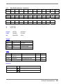
2.3.2
DVI-1 / DVI-2 Interface
The digital video inputs use the standard dual-link DVI interface. Dual-link DVI is necessary to support
the high data rate (dot clock) as required by this high resolution of 2048 x 2048. However, the monitor
also supports lower resolutions (e.g. VGA, SVGA, XGA, SXGA, UXGA, etc.) using a single link DVI
cable. This feature can be useful during boot up on some machines that use a lower resolution during
start-up.
The monitor provides EDID information (Extended Display Identification Data) to the host system
(workstation) via the DDC (Display Data Channel) protocol. This data includes, in addition to the
standard VESA timing, a special timing for 2048 x 2048 @ 60 Hz that is designed to use pixel
frequencies below the DVI maximum.
If the connected workstation/graphics card does not support DDC, it can be configured manually as
described in section 5.7 on page 56. In addition to this specific timing, all others timing that are part of
the DVI specification are displayed.
Video cables up to 5 meters in length may be used for the connection between the graphics card and
the display.
Connector Assignment:
Pin
1
2
3
4
5
6
7
8
9
10
11
12
13
14
15
Signal
TMDS-Data 2 TMDS-Data 2 +
TMDS-Data Shield 2 (GND)
TMDS-Data 4 TMDS-Data 4 +
DDC-CLK
DDC-DATA
NC
TMDS-Data 1 TMDS-Data 1 +
TMDS-Data Shield 1 (GND)
TMDS-Data 3 TMDS-Data 3 +
+5 V Power (In)
GND
Connector type: 29 pin DVI-I socket
24
2 General Installation
Pin
16
17
18
19
20
21
22
23
24
C1
C2
C3
C4
C5
Signal
Hot Plug Detect
TMDS-Data 0 TMDS-Data 0 +
TMDS-Data Shield 0 (GND)
TMDS-Data 5 TMDS-Data 5 +
TMDS-CLK Shield (GND)
TMDS-CLK +
TMDS-CLK NC
NC
NC
NC
GND
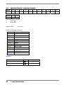
2.3.3
RS232-1 Interface
This RS232 interface is used for communication with the host machine (workstation). Three different
protocols are available which are described in chapter 4 on page 43.
In addition, this interface is used for monitor firmware updates
NOTE
Only the RS232-1 interface can be used for monitor firmware update.
Connector Assignment:
Pin
1
2
3
4
5
6
7
8
9
Signal
NC
TXD (Output)
RXD (Input)
NC
GND
NC
NC
NC
NC
2.3.4
RS232-2 Interface
Connector type: 9 pin D-Sub-socket
This RS232 interface is used for communication with the host machine (workstation). Three different
protocols are available which are described in chapter 4 on page 43. The additional handshake
signals serve to communicate with a workstation via the DDM protocol.
Connector Assignment:
Pin
1
2
3
4
5
6
7
8
9
Connector type: 9 pin D-Sub-socket
Signal
NC
TXD (Output)
RXD (Input)
DSR (Input)
GND
DTR (Output)
NC
NC
NC
2 General Installation
25
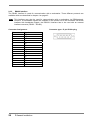
2.3.5
RS422 Interface
The RS422 interface is used for communication with a workstation. Three different protocols are
available which are described in chapter 4 on page 43.
NOTE This interface may also be used for communication with a workstation via DDM-protocol.
However, no handshake signals are available. If the monitor has to be connected via RS422
interface with handshake signals, the RS232-2 interface has to be used with an external
interface converter (RS232 – RS422).
Connector Assignment:
Pin
1
2
3
4
5
6
7
8
9
10
11
12
13
14
15
26
Signal
NC
TXD+
RXD+
NC
NC
NC
NC
NC
TXDRXDNC
NC
NC
NC
GND
2 General Installation
Connector type: 15 pin D-Sub-plug
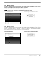
2.3.6
External OSD-Keyboard Interface
This connector is for an external passive keyboard which has exactly same functionality as the
buttons on the front of the panel, used to control the OSD (on screen display) (see section 3.1, page
28).
An external keyboard allows operation of the monitor when the front side keyboard is not accessible
or is absent. Cable length for this external keyboard should not exceed 7 meters.
The keys of the external keyboard pull the signal to ground (see following sketch).
1
2
Key ▲
3
Key ▼
4
Key Menu
5
Key Select
Connector Assignment:
Pin
2.4
Signal
1
GND
2
Key ▲
3
Key ▼
4
Key “Menu”
5
Key “Select”
Connector Type:
Sub miniature circular connector Series 712
(Binder GmbH)
Electrical Installation
Before connecting the Raptor SQ2801 to main power, ensure that all connectors for video signals and
serial interfaces are plugged in properly and securely.
After that, the monitor may be connected to main power and switched on by turning ON the main
power switch on the rear of the unit (see Fig. 12, page 22).
NOTE By default, automatic source scan is disabled and the DVI-1video input interface is activated.
A different video input interface can be selected via the OSD menu (see 3.2, page 29) or the
serial interfaces.
2 General Installation
27
3
Operation and Adjustment
The manual operation and adjustment of the monitor is facilitated by buttons that are integrated on the
front of the unit. The buttons are used for navigation and control of the OSD menu. Alternatively, all
adjustments for brightness, contrast, etc. can be carried out via an external keyboard or via the serial
interfaces (see chapter 4, page 43).
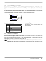
Fig. 14: OSD keyboard and LED
3.1
LED1
LED2
Function of OSD Keys and LED
The OSD keys have following function(s):
Source
▲
-
▼
-
Menu
-
Select
-
I/O
LED1
LED2
28
Increment value
Navigation to the right
Invoke Quick-OSD (if no OSD is active)
+ Selection of signal interface
+ execute automatic adjustment (for analog input source)
Decrement value
Navigation to the left
Invoke OSD menu
toggle between main- and submenu
Menu navigation, scroll down (if OSD is active)
Invoke Quick-OSD (if no OSD is active)
Selection of Quick-Menu-Function (Brightness, Contrast and backlight brightness)
Soft power
- On and off function of the monitor (Stand-By mode)
Status
Off:
valid input signal on selected video interface
Flashing: no valid input signal on selected video interface
On:
monitor in stand by mode
-
Power
Off:
On:
No main power or device switched off
Main power connected and device switched on
3 Operation and Adjustment
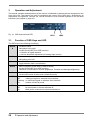
3.2
OSD-Menu / Quick-OSD-Menu
In addition to detailed adjustments in the OSD-Menu, there is another option available for adjusting
frequently used functions such as brightness and contrast via direct access (remotely), the so called
Quick-OSD-Menu. The protocols for access are discussed in Chapter 4.
All settings and adjustments of the OSD are stored in non-volatile memory.
3.2.1
Quick-OSD-Menu
Following settings / functions are available via Quick-OSD-Menu:
• Brightness
• Contrast
• Source select
• Automatic adjustment
Fig. 15:
Quick-OSD-Menu
Invoke via key < Select >
Function
Adjustment / Value
Description
Brightness
Setting range: 0 to 100
via key (▲/▼)
Brightness adjustment
Contrast
Setting range: 0 to 100
via key (▲/▼)
Contrast adjustment
Invoke via key <▲>
Function
Adjustment / Value
Description
Source RGB1
Digital1,Digital2
Press <▲> key again
Selection of input source
Automatic
Adjustment
Press <▲> key again
Performs an automatic image
adjustment. Adjustment of frequency,
phase and image position.
(Only available if source
“RGB1” is active)
3 Operation and Adjustment
29
3.2.2
OSD-Menu
The OSD (On Screen Display) is a menu system which is displayed on the screen. All monitor
settings and adjustments are done by operating the OSD
OSD options depend on the selected signal source (RGB or DVI). For example, functions for
frequency and phase adjustment of analog signal sources are not available when the unit is
displaying a DVI signal.
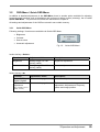
3.2.2.1 OSD-Menu – Picture
Fig. 16: OSD-Menu - Picture
Active Signal Source
Function
Description
Brightness
Display brightness adjustment (not backlight brightness!!!)
Setting range: 0 to 100
X
X
Contrast
Contrast adjustment
Setting range: 0 to 100
X
X
H-Position
Horizontal picture position
Setting range: 0 to 100
X
V-Position
Vertical picture position
Setting range: 0 to 100
X
Phase
Phase adjustment, see section 3.3.1 page 41
Setting range: 0 to 31
X
30
3 Operation and Adjustment
RGB
DVI
Function
Description
Frequency
Frequency adjustment, see section 3.3.1 page 41
Setting range: depends on input timing / resolution
Scaling adjustment if input resolution is lower than 2048 x 2048
Scaling
Setting range:
One to One:
Fill All:
Fill Aspect Ratio:
Auto Phase
Tune
RGB
DVI
X
X
X
Display signal without scaling.
The input signal is displayed full screen.
The input signal is displayed in maximum size
while height / width ratio is kept. Depending on
the resolution, a black field may be displayed
up and down or left and right.
Enable / disable automatic phase tune. If this function is enabled,
phase adjustment is periodically checked and if necessary
readjusted (see section 3.3.1 page 42).
Setting range: On, Off
X
(X): available for this input signal
3 Operation and Adjustment
31
3.2.2.2 OSD-Menu (Advanced)
Fig. 17: OSD-Menu (advanced)
Function
Description
RGB
DVI
Sharpness
Sharpness adjustment of the picture; choose from 1 = sharp to 5 =
smooth.
This function is only available, if the input resolution is lower than
target resolution 2048 x 2048.
Setting range: 1 to 5
X
X
Gamma
Gamma – Curve selection
Setting range: Linear or CRT
X
X
Colortemperature
Color temperature adjustment
Choose among three predefined and one free adjustable color
temperature values.
Enabling “user “ adjustment causes bars for red, green and blue to
appear. Range: 0 to 100 % (50 % corresponds factor 1)
Setting range: 5000 K, 7300 K, 9300 K, user
X
X
(X): available for this input signal
32
3 Operation and Adjustment
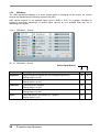
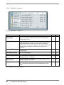
3.2.2.3 OSD-Menu - Options 1
Fig. 18: OSD-Menu - Options 1
Function
Description
RGB
DVI
OSD
Choose among nine predefined OSD positions
X
X
OSD H-Pos.
Shift OSD-menu in horizontal direction
Setting range: 0 to 100
X
X
OSD V-Pos.
Shift OSD-menu in vertical direction
Setting range: 0 to 100
X
X
OSD Timeout
Timeout for OSD menu; OSD disappears after that time, if no key
is pressed.
Setting range: in steps of 5 sec. between 5 and 60 sec.
X
X
OSD
Background
Choose between transparent and colored background
Setting range: Opaque; translucent
X
X
Backlight
Adjust backlight brightness
Setting range (backlight controller “off”): 0 to 100 %
Setting range (backlight controller “on”): 30 to 150 cd/m²
X
X
Backlight
Controller
Backlight control to compensate for loss of brightness due to
backlight aging (see section3.4 page 42).
Setting range: off; on
X
X
(X): available for this input signal
3 Operation and Adjustment
33
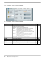
3.2.2.4 OSD-Menu - Options 2
Fig. 19: OSD-Menu - Options 2
Function
Description
RGB
DVI
DPMS
Display power management system
If DPMS is active, the monitor shuts down when there no sync
signals
Setting range: off; on
X
X
Source scan
Automatic scan for input sources; scans all input interfaces for
valid input signal.
Setting range: off; on
X
X
Source icon
Enable or disable display of source icon.
Changes to any of the following cause this icon to appear and
display the actual signal source information:
Signal source (e.g. RGB1 analog)
Mode, resolution of input signal source, Hand V-frequency.
X
X
SCI2-mode
Selection of communication protocol of serial interface RS232-2
and RS422 (see chapter 4 page 43).
Setting range: Standard; Sony DDM
X
X
X
X
SCI2-signal type Selection of active serial interface. Only one of the two interfaces
can be active.
Setting range: RS232; RS422
(X): available for this input signal
34
3 Operation and Adjustment
Function
DDM contrast
DDM brightness
Fans supervision
Description
DDM control function assignment to DDM protocol 0xA1
Valid functions: backlight, brightness, contrast, disabled
DDM control function assignment to DDM protocol 0xA0
Valid functions: backlight, brightness, contrast, disabled
ON: number of number of rotation will be shown in Menu Info 2
OFF: Status is OK in Menu Info 2
If a fan without control function is installed and status is ON;
menu Info 2 shows a failure.
RGB
X
DVI
X
X
X
X
X
3 Operation and Adjustment
35
3.2.2.5 OSD-Menu - Options 3
Fig. 20: OSD-Menu - Options 3
Function
Description
RGB-noise
suppression
This function suppresses interference at the sync signal lines
to avoid a new auto adjustment during short interference.
Setting range: off; on
X
X
Lock RGB-Timing 1
The current video timing will be stored and processed with
higher tolerances in H- and V- frequencies. These timings
will be used despite fluctuations in H- and V- frequency
resulting from a noisy video signal, which might otherwise be
misinterpreted, resulting in incorrect centering or pixel
resolution.
X
X
X
X
X
X
X
X
Unlock RGB-Timing 1 Settings for video timing 1 get released. Auto adjustment is
enabled again.
Lock RGB-Timing 2
See lock RGB-Timing 1
Unlock RGB-Timing 2 See unlock RGB-Timing 1
RGB DVI
RGB-Timing 1
Shows resolution and refresh rate of locked timing 1; Only
available if timing 1 is locked.
X
X
RGB-Timing 2
Shows resolution and refresh rate of locked timing 2; Only
available if timing 2 is locked.
X
X
Auto position
ON: the position will be automatic centered
OFF: the position depends on the auto adjustment of the
signal
X
(X): available for this input signal
36
3 Operation and Adjustment
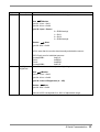
3.2.2.6 OSD-Menu – Utilities
Fig. 21: OSD-Menu – Utilities
Function
Description
RGB
DVI
Language
Select language of OSD Menu
Setting range: English; German
X
X
Calibration
This function allows to calibrate the A/D converter
X
Freeze frame
Saves the actual image
X
X
Factory reset
Reset of all parameters (brightness, contrast, backlight
brightness, etc.) to factory default values.
X
X
Installation
RGB-Mode
This function allows the user to add a signal timing definition
to the monitor. It will be used to process a signal that is not
internally defined.
X
X
Test pattern
Displays a test pattern on the screen. Select one of 7
different test patterns by pressing <▲> key. Any other key
will return to normal operation (no OSD).
X
X
(X): available for this input signal
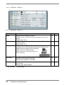
3 Operation and Adjustment
37
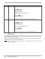
3.2.2.7 OSD-Menu - Utilities / Installation RGB-Mode
Fig. 22: OSD-Menu - Utilities / Installation RGB-Mode
Function
Description
RGB
DVI
Options
Select the RGB installation mode for those timings which are
not part of the internal timing list.
Disabled: use only the internal timing table.
Mode1:
use timing parameters and carry out complete
auto adjustment (most frequently used).
Mode 2: use timing parameters and carry out an auto
adjustment; however without an automatic image
position adjustment.
Mode 3: use timing parameters and carry out an auto
adjustment; however without an automatic
frequency adjustment.
Setting range: Disabled, Mode1, Mode2, Mode3
X
X
H-visible
Horizontal image resolution
X
X
V-visible
Vertical image resolution
X
X
H-total
Number of pixels per line (most important parameter)
X
X
H-Start
Number of pixels from H-sync start to image start
X
X
V-Start
Number of Lines from V-sync start to image start
X
X
Install
Activate installation parameters
X
X
(X): available for this input signal
38
3 Operation and Adjustment
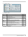
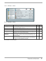
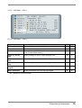
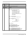
3.2.2.8 OSD-Menu - Infos 1
Fig. 23: OSD-Menu – Infos 1
Function
Description
RGB
DVI
FW
Shows the firmware version of the controller board
X
X
Temperature
Shows internal temperature
X
X
Power on time
Shows power-on time of the monitor (main power connected
to the unit and switched on)
X
X
Upper b.l. unit on
time
Shows backlight on time of upper backlight unit
X
X
Middle b.l. unit on
time
Shows backlight on time of middle backlight unit
X
X
Lower b.l. unit on
time
Shows backlight on time of lower backlight unit
X
X
Backlight power
surplus
Shows the reserve for adjusting the backlight brightness
X
X
Mode, Resolution
Shows parameters of the current input signal
X
X
(X): available for this input signal
3 Operation and Adjustment
39
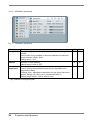
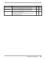
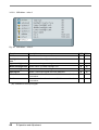
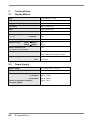
3.2.2.9 OSD-Menu - Infos 2
Fig. 24: OSD-Menu – Infos 2
Function
Description
RGB
DVI
Vdd-fuse
Shows status of main power fuse
X
X
Backlight inverter
fuse
Shows status of backlight inverter fuse
X
X
Upper backlight unit Shows status of upper backlight unit
X
X
Middle backlight unit Shows status of middle backlight unit
X
X
Lower backlight unit Shows status of lower backlight unit
X
X
Input signal
Shows if valid input signal has been detected
X
X
Fan 1
Shows the number of rotation and OK if the control function
is not active.
X
X
Fan 2
Shows the number of rotation and OK if the control function
is not active.
X
X
(X): available for this input signal
40
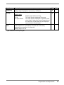
3 Operation and Adjustment
3.3
Adjustment Analog Signal Source (DDM)
There is no strict standardization for the signals coming from analog signal sources. Certain
adjustments are therefore necessary, depending on the graphics adaptors and used cables. When
the Raptor SQ2801 is connected to an analog signal source for the first time, an integrated “automatic
adjustment” function performs this adjustment. It uses the H and V frequencies of the input signal to
adjust the frequency, phase and picture position of the image. Depending on the quality of the
displayed image, it may be necessary to tweak the image manually.
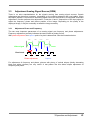
3.3.1
Adjustment Phase and Frequency
The two most important parameters of an analog signal are frequency and phase adjustments.
Frequency adjustment precisely indicates the total number of pixels per line.
With phase adjustment, the capture point of a pixel is determined. See the illustration below.
Pixel 1
Pixel 2
Pixel 3
Pixel 4
Video signal
Pixel clock
Phase adjustment
Capture
For adjustment of frequency and phase, pictures with plenty of vertical stripes (ideally alternating
black and white columns) are very useful. A test pattern like this allows simple adjustment of
frequency and phase.
3 Operation and Adjustment
41
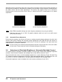
With bad frequency adjustment from left to right, parts of the picture appear blurred. Each alteration of
the frequency increases or decreases the number of blurred fields. Correct setting is achieved when
the whole screen has the same appearance. The picture may appear blurry, but it should be
homogeneously across the whole screen. Blurry or messy lines will be compensated for by phase
adjustment.
bad frequency adjustment
correct frequency adjustment
NOTE When DDM compatible timings are used, frequency adjustment may not get modified.
Frequency has to be set to 2816. All graphic adapters which are used in air traffic control
(ATC) use this setting.
3.3.2
Automatic Phase Adjustment
During normal operation, the monitor will heat up, causing marginal phasing between the pixel clock
and the video signal. Enabling the automatic phase adjustment in the OSD will allow the monitor to
compensate this. This function performs tests every 5 minutes for phasing in the pixel clock and
readjusts itself if a deviation is detected.
NOTE For best results, the automatic phase adjustment function requires that text or lines are visible
on the screen. These areas are used to evaluate the degree of phasing.
3.4
Adjustment of Backlight Brightness / Automatic Backlight Control
The monitor has an integrated automatic backlight control function which keeps backlight brightness
constant. If this function is enabled, the backlight value of the OSD is scaled to “cd/m²”.
This mode allows the user to set the backlight brightness to a value between 30 and 150 cd/m².The
TFT module’s maximum brightness is 210 cd/m² (with new backlight tubes). The difference from 150
to 210 cd/m² is used to compensate for old-age brightness leakage of the backlight tubes.
If automatic brightness control is disabled, the value can be set between 0 and 100 %.
42
3 Operation and Adjustment
4
Serial Communication
The Raptor SQ2801 features as described in Chapter 3 can be controlled via an application on the
host workstation. The host workstation can communicate with the Raptor SQ2801 via the serial
communication alternatives and protocols as described in this chapter.
There are two channels for serial communication available, in which one channel can be used
alternatively as RS232 or RS422 interface.
Channel 1
RS232
RS232-1
RS232
RS232-2
RS422
RS422
Channel 2
Switching between RS232-2 and RS422 is done in the OSD menu.
There are three different transmission protocols available:
Standard Protocol
This protocol supports all adjustments and controls of the monitor.
Simplified Protocol
This protocol has a simplified structure, and only allows the adjustment of brightness, contrast and
backlight brightness. It can also query the monitor’s system status for information such as error
messages, temperature, active source and operating time.
DDM-Protocol
This protocol is used in Sony-DDM compatible systems.
The following table shows which protocols are available for each of the different interfaces:
Standard Protocol
RS232-1
Simplified Protocol
RS232-1
DDM-Protocol
RS232-2
RS-422
RS232-2*
RS-422
* The RS232-2 interface has additional handshake signals which are needed for communication via DDM-protocol.
4 Serial Communication 43
4.1
Standard Protocol
The standard protocol supports all adjustments and control of the monitor. This protocol uses two
kinds of data packet types. Packet format called “Operation” is used for adjustments such as
brightness, contrast and backlight brightness. The packet type called “key simulation” is used to
operate the OSD via serial interface.
Interface Parameters
Baud-Rate
19200
Parity
None
Data-Bits
8
Stop Bits
1
Handshake
No
Protocol
Monitor
Host
Operation / Key
ACK(OK)
Operation(GET)
ACK(OK)
OpPack
0x1E
ACK-Message
OK
0x06
Error
0x15
44
4 Serial
erial Communication
4.1.1
Data Packet Structure “Operation”
Byte No
Data
Byte No
Data
Byte No
Data
0
1
2
3
4
5
0xBE
0xEF
0x03
0x19
0x00
CRC-L
11
12
13
14
15
16
17
18
19
20
21
0x00
0x00
0x00
0x00
0x00
Val-L
Val-1
Val-2
Val-H
0x00
0x00
22
23
24
25
26
27
28
29
30
31
0x00
0x00
0x00
0x00
0x00
0x00
0x00
0x00
0x00
0x00
-L
= Lower Byte
-H
= Higher Byte
O-Type
(BYTE)
: Operation
Code
(WORD)
: Function
Val
(DWORD)
: Value
6
7
8
9
CRC-H O-Type Code-L Code-H
10
0x00
O-Type
Code
Operation
Comment
0x01
SET
Set value
0x02
GET
Get value
0x03
INC
Increment value
0x04
DEC
Decrement value
Code
Code
Operation
Comment
Val Min Val Max
0x03E8
Backlight
brightness
Set backlight value
0
0xff
0x139C
Brightness
Set brightness level
0
0xff
0x13AF
Contrast
Set contrast level
0
0xff
Protocol
Host
Monitor
Operation packet
Char 0x1E + Operation packet
4 Serial Communication 45
4.1.2
Data Packet Structure “Keyboard Simulation”
0
1
2
3
4
5
0xBE
0xEF
0x02
0x06
0x00
CRC-L
11
12
0x00
0x00
Byte No.
Data
Byte No.
Data
L
= Lower Byte
H
= Higher Byte
Code (WORD)
: Key code
Following codes are supported:
Key code
Function / Key
0x0061
+
0x0062
-
0x005b
UP
0x0059
DOWN
0x005a
LEFT
0x0058
RIGHT
0x0057
MENU
0x005c
MENU RIGHT
0x005d
MENU LEFT
0x005f
ESCAPE
0x0056
AUTOADJ.
0x0055
SOURCE
Protocol
Host
Monitor
Packet "Keyboard simulation"
Char 0x06
46
4 Serial
erial Communication
6
7
8
CRC-H Code-L Code-H
9
10
0x00
0x00
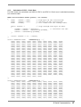
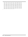
4.1.3
Calculation of CRC - Check Sum
For CRC check sum calculation set 0x00 for CRC-L and CRC-H. Check sum is calculated according
to a reference table.
WORD CalculateCRC16(BYTE *pcData, int nCount)
{
BYTE
cCRCHi = 0xFF;
// high byte of CRC initialised
BYTE
cCRCLo = 0xFF;
// low byte of CRC initialised
BYTE
cIndex;
// will index into CRC lookup table
while (nCount--)
// step through each byte of data
{
cIndex = cCRCHi ^ *pcData++;
// calculate the CRC
cCRCHi = cCRCLo ^ cCRCHiArray[cIndex];
cCRCLo = cCRCLoArray[cIndex];
}
return (cCRCHi << 8) + cCRCLo;
}
static CROMDATA
0x00, 0xC1,
0x80, 0x41,
0x00, 0xC1,
0x80, 0x41,
0x00, 0xC1,
0x81, 0x40,
0x00, 0xC1,
0x81, 0x40,
0x00, 0xC1,
0x80, 0x41,
0x01, 0xC0,
0x81, 0x40,
0x00, 0xC1,
0x80, 0x41,
0x01, 0xC0,
0x80, 0x41,
0x00, 0xC1,
0x80, 0x41,
0x00, 0xC1,
0x80, 0x41,
0x01, 0xC0,
0x80, 0x41,
0x01, 0xC0,
0x81, 0x40,
0x00, 0xC1,
0x80, 0x41,
};
BYTE
0x81,
0x00,
0x81,
0x01,
0x81,
0x01,
0x81,
0x00,
0x81,
0x00,
0x80,
0x01,
0x81,
0x00,
0x80,
0x01,
0x81,
0x00,
0x81,
0x00,
0x80,
0x00,
0x80,
0x00,
0x81,
0x00,
cCRCHiArray[] =
0x40, 0x01, 0xC0,
0xC1, 0x81, 0x40,
0x40, 0x00, 0xC1,
0xC0, 0x80, 0x41,
0x40, 0x01, 0xC0,
0xC0, 0x80, 0x41,
0x40, 0x01, 0xC0,
0xC1, 0x81, 0x40,
0x40, 0x01, 0xC0,
0xC1, 0x81, 0x40,
0x41, 0x01, 0xC0,
0xC0, 0x80, 0x41,
0x40, 0x01, 0xC0,
0xC1, 0x81, 0x40,
0x41, 0x00, 0xC1,
0xC0, 0x80, 0x41,
0x40, 0x01, 0xC0,
0xC1, 0x81, 0x40,
0x40, 0x00, 0xC1,
0xC1, 0x81, 0x40,
0x41, 0x00, 0xC1,
0xC1, 0x81, 0x40,
0x41, 0x01, 0xC0,
0xC1, 0x81, 0x40,
0x40, 0x01, 0xC0,
0xC1, 0x81, 0x40
{
0x80,
0x01,
0x81,
0x00,
0x80,
0x01,
0x80,
0x01,
0x80,
0x00,
0x80,
0x00,
0x80,
0x00,
0x81,
0x00,
0x80,
0x01,
0x81,
0x01,
0x81,
0x00,
0x80,
0x01,
0x80,
0x41,
0xC0,
0x40,
0xC1,
0x41,
0xC0,
0x41,
0xC0,
0x41,
0xC1,
0x41,
0xC1,
0x41,
0xC1,
0x40,
0xC1,
0x41,
0xC0,
0x40,
0xC0,
0x40,
0xC1,
0x41,
0xC0,
0x41,
0x01,
0x80,
0x01,
0x81,
0x00,
0x80,
0x00,
0x80,
0x01,
0x81,
0x00,
0x81,
0x01,
0x81,
0x01,
0x81,
0x01,
0x80,
0x01,
0x80,
0x01,
0x81,
0x00,
0x80,
0x01,
0xC0,
0x41,
0xC0,
0x40,
0xC1,
0x41,
0xC1,
0x41,
0xC0,
0x40,
0xC1,
0x40,
0xC0,
0x40,
0xC0,
0x40,
0xC0,
0x41,
0xC0,
0x41,
0xC0,
0x40,
0xC1,
0x41,
0xC0,
static CROMDATA
0x00, 0xC0,
0x07, 0xC7,
0x0F, 0xCF,
0x08, 0xC8,
0x1E, 0xDE,
0xD5, 0x15,
0x11, 0xD1,
0xF2, 0x32,
0x3C, 0xFC,
0x3B, 0xFB,
0xEB, 0x2B,
0xEC, 0x2C,
BYTE
0xC1,
0x05,
0xCE,
0xD8,
0xDF,
0xD7,
0xD0,
0x36,
0xFD,
0x39,
0x2A,
0xE4,
cCRCLoArray[] =
0x01, 0xC3, 0x03,
0xC5, 0xC4, 0x04,
0x0E, 0x0A, 0xCA,
0x18, 0x19, 0xD9,
0x1F, 0xDD, 0x1D,
0x17, 0x16, 0xD6,
0x10, 0xF0, 0x30,
0xF6, 0xF7, 0x37,
0x3D, 0xFF, 0x3F,
0xF9, 0xF8, 0x38,
0xEA, 0xEE, 0x2E,
0x24, 0x25, 0xE5,
{
0x02,
0xCC,
0xCB,
0x1B,
0x1C,
0xD2,
0x31,
0xF5,
0x3E,
0x28,
0x2F,
0x27,
0xC2,
0x0C,
0x0B,
0xDB,
0xDC,
0x12,
0xF1,
0x35,
0xFE,
0xE8,
0xEF,
0xE7,
0xC6,
0x0D,
0xC9,
0xDA,
0x14,
0x13,
0x33,
0x34,
0xFA,
0xE9,
0x2D,
0xE6,
0x06,
0xCD,
0x09,
0x1A,
0xD4,
0xD3,
0xF3,
0xF4,
0x3A,
0x29,
0xED,
0x26,
4 Serial Communication 47
0x22,
0x61,
0xA5,
0x6E,
0x78,
0x7F,
0x77,
0x70,
0x96,
0x5D,
0x99,
0x8A,
0x44,
0x43,
0xE2,
0xA1,
0x65,
0xAE,
0xB8,
0xBF,
0xB7,
0xB0,
0x56,
0x9D,
0x59,
0x4A,
0x84,
0x83,
0xE3,
0x63,
0x64,
0xAA,
0xB9,
0x7D,
0xB6,
0x50,
0x57,
0x5F,
0x58,
0x4E,
0x85,
0x41,
0x23,
0xA3,
0xA4,
0x6A,
0x79,
0xBD,
0x76,
0x90,
0x97,
0x9F,
0x98,
0x8E,
0x45,
0x81,
};
48
4 Serial Communication
0xE1,
0xA2,
0x6C,
0x6B,
0xBB,
0xBC,
0x72,
0x91,
0x55,
0x9E,
0x88,
0x8F,
0x87,
0x80,
0x21,
0x62,
0xAC,
0xAB,
0x7B,
0x7C,
0xB2,
0x51,
0x95,
0x5E,
0x48,
0x4F,
0x47,
0x40
0x20,
0x66,
0xAD,
0x69,
0x7A,
0xB4,
0xB3,
0x93,
0x94,
0x5A,
0x49,
0x8D,
0x46,
0xE0,
0xA6,
0x6D,
0xA9,
0xBA,
0x74,
0x73,
0x53,
0x54,
0x9A,
0x89,
0x4D,
0x86,
0xA0,
0xA7,
0xAF,
0xA8,
0xBE,
0x75,
0xB1,
0x52,
0x9C,
0x9B,
0x4B,
0x4C,
0x82,
0x60,
0x67,
0x6F,
0x68,
0x7E,
0xB5,
0x71,
0x92,
0x5C,
0x5B,
0x8B,
0x8C,
0x42,
4.2
Simplified Protocol
The simplified protocol uses a data packet structure similar to the standard protocol, however with
reduced functional range. Calculation of CRC check sum is similar to description in section 4.1.3 page
47.
Interface Parameters
Baud-Rate
Parity
19200
Data-Bits
8
Stop Bits
1
Handshake
No
None
ACK-Message
0x06
OK
Protocol
Host
Monitor
Control Packet
Data Packet
or ACK (OK)
Maximum response time of the monitor is 200 ms. In case of an error in transmission, the monitor
does not respond.
4.2.1
Data Packet Structure
Byte No
Data
Byte No
Data
0
1
2
3
4
5
6
7
8
9
10
0xBE
0xEF
0x10
Len-L
Len-H
CRC-L
CRC-H
CMD
Data 0
Data 1
Data
11
12
13
14
15
16
17
18
19
20
Data
Data
Data
Data
Data
Data
Data
Data
Data
Data
-L
= Lower Byte
-H
= Higher Byte
CMD
(BYTE)
: Command
Len-L / H
(WORD)
: Number of data bytes CMD + Data 0 to Data xx
4 Serial Communication 49
CMD
Code
Command
Comment
0x01
Status
Reply of system status
Host
Monitor
Byte 03: L-Len = 0x01
Byte 04: H-Len = 0x00
Monitor
Host
Byte 03: L-Len = 0x0E
Byte 04: H-Len = 0x00
Byte 08: Status Information Display Module
- Bit 0: VDD - fuse faulty
- Bit 1: Backlight inverter – fuse faulty
- Bit 2: Upper backlight unit faulty
- Bit 3: Middle backlight unit faulty
- Bit 4: Lower backlight unit faulty
- Bit 5: No or no valid input signal from controller
- Bit 6: reserved
- Bit 7: reserved
Byte 09: Internal Temperature
-55°C to +125°C in complement on two
Byte 10: Active Input Source
- Bit 0..1:
0 = RGB-Analog1
1 = DVI1
2 = DVI2
3 = RGB-Analog2
- Bit 2: Input signal active
Byte 11: reserved
Byte 12: reserved
Byte 13: LSB Operating hour meter
Byte 14: Second Byte Operating hour meter
Byte 15: Third Byte Operating hour meter
Byte 16: MSB Operating hour meter
Byte 17: LSB Backlight- Operating hour meter
Byte 18: Second Byte Backlight- Operating hour meter
Byte 19: Third Byte Backlight- Operating hour meter
Byte 20: MSB Backlight- Operating hour meter
50
4 Serial
erial Communication
Code
Command
Comment
0x02
Source Switch This command enables the host to switch signal source.
Host
Monitor
Byte 03: L-Len = 0x01
Byte 04: H-Len = 0x00
Byte 08: Input - Source
0 = RGB-Analog1
1 = DVI 1
2 = DVI 2
3 = RGB-Analog2
Monitor
Host
Byte 00: ACK = 0x06
ACK is sent after the monitor has internally switched the source.
CRC-Check sum for individual sources::
- AnalogRGB1:
0x2C1C
- DVI1:
0xEDDC
- DVI2:
0xADDD
- AnalogRGB2:
0x6C1D
0x03
Backlight Brightness
This command is used to adjust backlight brightness
Host
Monitor
Byte 03: L-Len = 0x02
Byte 04: H-Len = 0x00
Byte 08: Value of Brightness (0 .. 255)
Monitor
Host
Byte 00: ACK = 0x06
Value 0 to 255 corresponds 0 to 100% of adjustment range.
4 Serial Communication 51
Code
Command
Comment
0x04
Brightness
This command is used to adjust brightness (black level).
Host
Monitor
Byte 03: L-Len = 0x02
Byte 04: H-Len = 0x00
Byte 08: Brightness value (0 .. 255)
Monitor
Host
Byte 00: ACK = 0x06
Value 0 to 255 corresponds 0 to 100% of adjustment range.
0x05
Contrast
This command is used to adjust contrast.
Host
Monitor
Byte 03: L-Len = 0x02
Byte 04: H-Len = 0x00
Byte 08: Contrast value (0 .. 255)
Monitor
Host
Byte 00: ACK = 0x06
Value 0 to 255 corresponds 0 to 100% of adjustment range.
4.3
DDM-Protocol
The DDM-Protocol and its commands have been defined for operation with Sony DDM compatible
monitor. The Raptor SQ2801 only implements those commands which the monitor supports. All other
commands will simply return success.
This protocol is only supported by RS232-2 or RS422 interface. For this the DDM protocol and the
appropriate interface must be selected in the OSD.
NOTE
52
Data transmission with handshake signals is only supported by RS232-2 interface (see
section 2.3.4 page 25).
4 Serial Communication
List of implemented commands:
Code
Command
Comment
0xA0
Operator
Brightness
This command is used to set Backlight brightness.
0xA1
Operator Contrast
This command is used to set contrast.
Code
Command
Comment
0xB8
Status
Response System Status
Byte 0: Status Information Display-Module
- Bit 0: VDD-fuse faulty
- Bit 1: Backlight inverter-fuse faulty
- Bit 2: Upper backlight unit faulty
- Bit 3: Middle backlight unit faulty
- Bit 4: Lower backlight unit faulty
- Bit 5: No or no valid signal from controller
- Bit 6: reserved
- Bit 7: reserved
Byte 1: Internal Temperature
-55°C to +125°C in complement on two
Byte 2: Active Input Source
- Bit 0..1:
0 = RGB-Analog1
1 = DVI1
2 = DVI2
3 = RGB-Analog2
- Bit 2: Input signal active
Byte 3: Reserved
Byte 4: LSB Operating hour meter
Byte 5: Second Byte Operating hour meter
Byte 6: Third Byte Operating hour meter
Byte 7: MSB Operating hour meter
Byte 8: LSB Backlight- operating hour meter
Byte 9: Second Byte Backlight- operating hour meter
Byte 10: Third Byte Backlight- operating hour meter
Byte 11: MSB Backlight- operating hour meter
4 Serial Communication 53
5
Technical Data
5.1
Display Module
Type
Color active TFT-LCD
Diagonal
28.05"
Display area (WxH)
503.808 x 503.808 mm²
Resolution
2048 x 2048 Pixel
Pitch
0.246 x 0.246 mm²
Colors
16.7 Million
Viewing angle typ.
horizontally
vertically
(CR >= 10)
1000 : 1
Contrast ratio typ.
Response time
± 85°
± 85°
White
Black
Black
White
5 ms
20 ms
1,25
White Uniformity max.
(max. luminance / min. luminance)
3 x CCFT-Trays
(Cold Cathode Fluorescent Tube)
Backlight
Brightness typ.
5.2
max.
min.
225 cd/m²
22,5 cd/m²
Power Supply
Input voltage
90 - 264 VAC (47 – 63 Hz)
Main power fuse
2 x 5 A delay action fuse
Power consumption typ.
at 70 cd/m² approx. 110 W
at 210 cd/m² approx. 150 W
Power consumption Stand by
(no input signal)
54
5 Technical Data
approx. 15 W
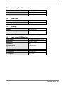
5.3
Operating Conditions
Operating temperature
0 to +40 °C
Storage temperature
-25 to +60 °C
Humidity
max. 95 % (no condensation)
5.4
Protection
Protection
None
Front shield
antireflective
5.5
Housing
Weight
approx. 29.1 kg
Material of housing
Sheet steel
Color of housing
RAL 9005 (jet black)
5.6
Input signal RGB analog
Level (Video)
0.7 Vss RGB analog on 50 Ω
Bandwidth
500 MHz (-3dB)
Impedance
50 Ω
Synchronization
Separate Sync
Synchronization (level)
1 - 5 Vss
Impedance
75 Ω
H- Frequency
30 to 130 KHz
V- Frequency
50 to 70 Hz
5 Technical Data
55
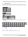
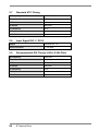
5.7
Standard ATC-Timing
H-Frequency
126.84 KHz
Pixel clock
357 MHz
H-Total
2816 pixel
H-Visible
2048 pixel
V-Frequency
60 Hz
V-Total
2114 lines
V-Visible
2048 lines
5.8
Input Signal DVI-1 / DVI-2
Signal
Standard DVI 1.0
Pixel clock max.
2 x 165 MHz
5.9
Recommended DVI-Timing 2,048 x 2,048 Pixel
H-Frequency
124.8 KHz
Pixel clock
260 MHz (2 x 130 MHz)
H-Total
2080 pixel
H-Visible
2048 pixel
V-Frequency
60 Hz
V-Total
2100 lines
V-Visible
2048 lines
56
5 Technical Data
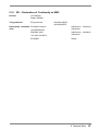
5.10
EU – Declaration of Conformity on EMC
Product
LCD-Monitor
Raptor SQ2801
Test guidelines
EG-guide lines
Harmonized standards EN 55022 Class B
used
+A1/EN55022/A1
EN55024:1998
+A1:2001+A2:2003
EN 60950
No 2004/108/EC
No 2006/95/EC
Interference
(industrial)
emissions
Interference resistance
(industrial)
Safety
5 Technical Data
57
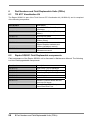
6
Part Numbers and Field Replaceable Units (FRUs)
6.1
TSI ATC Visualization Kit
The Raptor SQ2801 is part of the Tech Source ATC Visualization kit (19-0206-01) and is comprised
of the following components:
Part Number
Description
19-0152-01
Raptor 2500T-DL 2Kx2K Graphics
Accelerator
19-0201-01
Raptor SQ2801 Display (Desktop
version)
15-0231-01
Dual Link DVI cable
73-0066-01
Raptor OpenWindows software
(Solaris drivers)
65-0228-01
Raptor OpenWindows manual
(Raptor Graphics hardware and
software installation manual)
65-0265-01
Raptor SQ2801 Reference &
Maintenance manual
6.2
Raptor SQ2801 Field Replaceable components
Field maintenance of the Raptor SQ2801 unit is discussed in Maintenance Manual. The following
is a list of field upgradeable components:
Part Number
Description
80-0010-01
Upper Lamp Tray for Backlight
80-0010-02
Middle Lamp Tray for Backlight
80-0010-03
Lower Lamp Tray for Backlight
80-0011-01
Power Supply
80-0012-01
Fan with cover
80-0013-01
Interface Controller board with two
Dual Link DVI inputs
80-0011-02
20 mm, 5 Amp, 250 V Delay
Action/Slow Blow Fuse
58
6 Part Numbers and Field Replaceable Units (FRUs)
1st Edition-October, 2007
03V22230A1
(U.M-SQ2801-EN)