1
Chapter 15
wrench. A few sensors can only be removed with a special
socket. Always disconnect the electrical connector from the
wiring harness before installing the socket over the sensor.
Caution: Sensors installed in aluminum parts
should not be removed until the engine has cooled
for several hours. This cooling period is necessary
to prevent damage to the threads in the aluminum part.
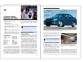
Computer System Diagnosis and Repair
303
Before installing the new sensor, coat the threads with
the proper sealant. When installing the sensor, do not overtighten it, as this may damage the threads or distort the sensor
shell. If the cooling system was drained, refill it before
restarting the engine. Leave the radiator cap loose and
recheck coolant level after allowing the engine to run for about
10 minutes. A few front-wheel drive engines require a special
fill procedure. Follow the manufacturer’s recommendations.
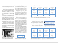
The bleed valve shown in Figure 15-50 can be loosened to
remove air from the cooling system.
Note: When bleeding air from a cooling system,
turn on the heater with the blower fan on high. This
will provide additional cooling and fluid circulation
during the bleeding process.
Intake Air and Exhaust Gas Temperature Sensors
Intake air and exhaust gas temperature sensors are not
under pressure when the engine is not running. Intake air
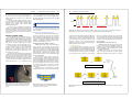
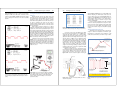
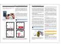
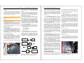
Figure 15-49. Loosen the radiator cap before servicing any part
of the cooling system.
Bleed valve
temperature sensors can be removed and replaced without
special precautions. To replace a temperature sensor installed
in the intake manifold or plenum, disconnect the electrical
connector. Then use the proper socket to remove the sensor
from the manifold. Coat the new sensor with sealing
compound (if necessary), install it in the manifold, and reattach the electrical connector. Check for vacuum leaks and
sensor operation.
To replace a temperature sensor installed in the air
cleaner housing, remove the electrical connector, pull the
attaching clip from the sensor, and remove the sensor from
the housing. Position the new sensor in the housing, install the
clip, and reconnect the electrical connector.
To replace an exhaust gas temperature sensor, allow the
exhaust system to cool; then disconnect the electrical
connector. Use a special tool or a six-point socket to remove
the sensor without damaging its shell. Place anti-seize
compound on the threads of the new sensor. Install the sensor
and reconnect the electrical connector. Start the engine and
check for exhaust leaks and proper sensor operation.
Crankshaft/Camshaft Position Sensors
Most crankshaft and camshaft position sensors are
installed on the engine block, timing cover, camshaft housing,
or transmission bell housing. These sensors are secured by a
clamp and a single bolt or attached to a bracket held by one
or more bolts. After removing the electrical connector and
bolt(s), pull the position sensor from the engine.
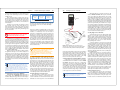
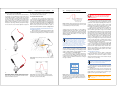
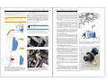
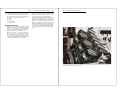
Check the end of the sensor to ensure that it
has not contacted the crankshaft or camshaft sensor ring,
Figure 15-52. If the end of the sensor has been damaged by
contact with the sensor ring or other moving parts, determine
the cause and make the necessary corrections before
installing a new sensor.
To install the new sensor, make sure replacement
O-rings or gaskets are in place. Then lightly lubricate the
sensor’s tip with engine oil and push the sensor into position.
Reinstall the clamp and bolt; then install the electrical
connector.
Terminal
Knock
sensor
A
Sensor
tip
Threads
Connector
B
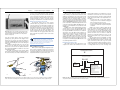
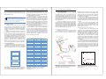
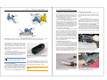
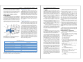
Figure 15-51. A—Knock sensors are threaded into the engine.
This one is located under the intake manifold. B—External parts
of a knock sensor. (General Motors and Ford)
Check tip for
damage
ECM Service
C
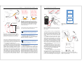
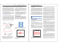
Figure 15-48. This figure shows the sequence of steps
necessary to remove a throttle position sensor. A—Remove the
electrical connector. B—Loosen and remove the attaching bolts.
C—Remove the sensor from the shaft. Note the position of the
throttle shaft for reinstallation. (General Motors)
Auto Diagnosis, Service, and Repair
Knock Sensor Replacement
Knock sensors are threaded directly into the engine
block, cylinder head, or intake manifold, Figure 15-51. This
allows them to easily detect and transmit the sound of engine
detonation. Knock sensors can be removed and replaced
without special precautions. Since the knock sensor shell is
usually made of brass, never try to remove this type of sensor
with an open-end wrench. Install and tighten the new sensor
carefully. Use a socket or box-end wrench to avoid distorting
the shell. After tightening, reinstall the electrical connector and
check the operation of the knock sensor as explained earlier.
A
B
304
Figure 15-50. After the coolant temperature sensor has been
replaced, it may be necessary to bleed air from the cooling system. Some engines are equipped with bleed valves. This one is
located on the thermostat housing.
Before replacing an ECM, make sure the ignition switch
is turned to the off position. Disconnect the negative battery
cable, if recommended by the manufacturer. After locating the
ECM, disconnect the wiring connector(s) and remove the
attaching fasteners. Most ECMs are attached to the vehicle
Figure 15-52. After removing a crankshaft or camshaft position
sensor, check its tip for signs of damage. If damage is found, be
sure to determine and correct the cause before installing a new
sensor.