1
Lucss
F a u f tD i a g n o s i s
S e r v i c eM a n u a l
m- &,
ia._
trwtrFi]
U i,rull
w7
/ \
oott
@
F.,
t__j
C a t a l oN
g o .X l A l 1 6
F a u l tD i a g n o s i s
S e r v i c eM a n u a l
Informationcontainedhereinhasbeencarefully
researched
reliablesources.Whileall information
is believed
to be completeand accurate,
we cannotacceptresponsibility
for anyerroror omission.We reserve
the right
t o m a k ea n y n e c e s s a rcyh a n g e sa t a n yt i m e ,w i t h o u tn o t i c e .S h o u l da n e r r o ro r o m i s s i o n
b e f o u n d ,p l e a s e
reportit immediatelyto the LucasAftermarket
OperationsMarketingDepartment.
lntroduction
F a u l td i a g n o s i s itsh em e t h o do i l o c a t i n gf a u l t sw h i l et h ee l e c t r i c aelq u i p m e ni st s t i l li n s i r u .
ln rlre
interestsof efficiency
and.economy,
the?iagnosismust be accuratednd mustbe carriedort in ii.,.
s h o r t e spt o s s i b l et i m e u s i n gt,h e m i n i m u m - a m o u nor f e q u i p m e n t .l t i s t h e a i r n o r i t i i i " " r ' i "
presenta logica.lseqqgnc_e3f
tgststhat may be carriedout bn' the varioussections
or tneequilmen t
in order to achievethis objective
The.majorito
y f p r o c e d u r ei n
s v o l v ec i r c u i tr e s t i n ga n d t h e p r i n c i p l eu s e dw i l l b e t h a t o t ' c l r e c k i n g
l o r " v o l t a g ed r o p " w h e r ea v o l t m e t e irs c o n n e c l e di n p a i a l l e lw i t h t h e p a r t i c u l a r . i r c r l t
io-U!
tested.
As.voltagedrop existsonly whencurrentis flowingand variesaccordingto the amount.of
current
i t i s e s s e n t i at h
l a t t h e c i r c u i ti s c h e c k e d" u n d e r - l o a d " ,1 . . . * f i i l i i p a - s s i n !i t r ' r " i * r i ' . r . r . " , .
ln certaininstancesthis currentwill be measuredusinga testammeiei.
T h e a c c e p t a b lveo l t d r o p f i g u r ef o r m o s tc i r c u i t si s l O / , o f s y s t e mv o l t a g e( 1 . 2v o l t so n a
l2 voir
system)but thereareexcep-tions
to thisrule as in the caii of the starterciiuit wherethe maximum
voltagedrop allowedis 0.5 volts.
Throughoutthe procedures
whereveran exceptionappliesthis figurewill be clearlystated.
T h e f o l l o w i n gi s t h e m i n i m u me q u i p m e nnt e c e s s a rt yo c a r r yo u t t h i s f a u l td i a g n o s i s :
l. D.C. voltmeter(movingcoil; 4" openscale0_40volts.
2. -D.C.am,meter
(movingcoil) 4" openscaletO_0_100
amp.'
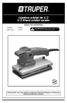
Note: The voltmeterand ammetercan be obtainedin a test box form as sho*,n.
l . H y d r o m e t e(rF i g . l ) .
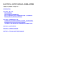
4. Heavyduty batterydischargetester(Fig. 2).
5. Ohmmeter.
Page2
Fig. 1
T y p i c a lt e s ! b o x a n d h y d r o m e t e r
Fig. 2
H e a v y d g s y b a c c e r yd i s c h a r g et e s r e r
Contents
Page(s)
2
INTRODUCTION .,.
BATTERIES
)-v
STARTERS
l0- t4
IU
Battery check
Checkingthe startersystem(inertiadrives)
drives)
Checkingthe startersystem(pre-engaged
l0-ll
l2-t4
l5-25
COIL IGNITION
16-r9
t9-21
Standardcoil ignitionsystem
Ballastedignition sYstem
Opus ignitiontestProcedure
Staticignitiontiming
timing
Stroboscopic
1a
25
25
26-30
DYNAMOS AND CONTROL BOXES
26
26-21
27
7'7-28
29
29-30
Battery test
Checkingdynamo
Checking dynamo leads
Compensatedvoltage cont
Ignition warning light
Current voltage control
J I _ J /
ALTERNATORS
Batterytest
i0/ll AC systems
l 5 l l 6 l l 7 l l 8 l 2 0 A C Rs y s t e m s
Battery test
32
32-35
36-37
...
JO
3 8- 4 l
LIGHTING
Sideand tail light circuit
...
.
Voltageat the batteryunde, ' t " " 0 . . . . . .
Headlights,stop iightsancidirectioninciicatorcircuits...
Headlampalignment
WIPER MOTORS
Wiper testprocedure
1A
)t
...
..
39
39
4l
42-44
42
Page3
BATTERIES
INTRODUCTION
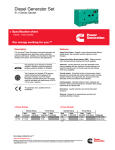
B A T T E R I E Sl N s E R V l c E ( F i g . 3 )
The lead-acidbatteryis a deviceusedto convertand
store electrjcalenergyin a chemicalform and as the
n a m e i m p l i e st h e b a s i ca c t i v em a t e r i a l sa r e l e a d a n d
sulohuricacid.
fhe purpos"of the batteryon thevehicleis primarily
to provide current for the operation of the starter
b u t i t a l s os u p p l i e so t h e re q u i p m e ntth a t m a y b e u s e d
w h i l s t t h e v e h i c l ei s s t a t i o n a r y e. . g . r a d i o , p a r k i n g
lightse
, tc.
During the courseof normal running,the batteryis
recharged
by the vehiclechargingsystemand provided
the vehicledoesenoughrunningtime, will havestored
energyreadyfor the next start operation.
N o t e : A v e h i c l es t a n d i n gi d l e w i l l z D r m a i n t a i n a
chargedbattery.
As a battery fault can have adverseeffectson the
operation of the various systems,particularly the
starting and charging system,some knowledgeol
b a t t e r yt e s t i n gi s a n e s s e n t i apla r t o f f a u l t d i a g n o s i s .
l . C L E A N A N D D R Y - t h e b a t t e r yp, a r t i c u l a r l tyh e
t o p m u s tb e k e p tc l e a na n dd r y . W a t e rs p i l l a g e ! c .
during topping-up must be immediatelywiped
away.
2 . E L E C T R O L Y T E L E V E L- t h e e l e c t r o l y t em u s t
b e m a i n t a i n e da t r h e c o r r e c t h e i s h t w h i c h i s
n o r m a l l yl e v e lw i t h t h e t o p s o f t h e - s e p a r a t o o
r sr
t h es p l a s h g u a r d .
l . T O P P I N C - U P - s h o u l db e c a r r i e do u t w h e n t h e
electrolytefalls below the correct level. Only
distilledwater or de-ionised
water must be added
to replaceelectrolyte
lost by evaporation.
4 . S T A T E O F C H A R G E - t h e b a t t e r ym u s tn e v e rb e
lelt in a disdharged
state. A batteryin a poor state
of chargei.e.lessthanT0l shouldbe rem6vedand
chargedfrom an independent
sourceat the normal
rechargerate. Otherwisethe platesmay become
( h a r d e n e dm) a k i n gi t d i f f i c u l tt o a c c e p r
sulphated
CLEANAND DRY
_'--
CORRECT
ELECTROLYTE
LEVEI
\'
SM
WITH
PETR(
JELLY
& DRY
Fig.3
B a t t e n e si n s e r v r c e
Page5
a charge,with the consequent
early failure of the
battery.
Ensurethat the generatordrive belt is adjusted
correctlyand that it does not rest on the bottom
of thepulleys.
5. 'clamped
INSTALLATION - the battery mu'st be securely
(not overtight)to preventdamagefrom
vibration, which may causesheddingof active
material from the plates resultingin a loss of
capacityor short-circuitbetweenthe plates,
The stowagearea.mustalso be kept cleanand dry.
Any acid spillageshould be removedwith household ammonia or baking soda and hot water.
otherwisethe metalwill be extensively
damagedby
corrosion. The metalwork should be repainted
w i t h a c i d - r e s i s t i npga i n t a f t e r t h e c o r r o s i o nh a s
beenneutralised.
C A R E o F B A T T E R Y L U G S ( F i g .a )
The effectof acid corrosionis far more seriousthan
is generallyrealised.For example,excessive
corrosion
of the batterylugswill leadto sluggishoperationof rhe
starter. This is due to voltagedrop at the battery
terminals,when the high startercurrentis flowing.
The lead die-cast lug is designedto reduce rhe
possibilityof corrosion to a minimum and is fitted
almostexclusively
to Britishcarstoday.
T h e S . M . M . T . l u g , c l a m p t y p e ,i s u s e dm a i n l y o n
commercialand passenger
vehicles.
ln both casesthe lug shouldbe clearedof oxidation
and the lug and battery post smearedwith petroleum
jelly as an addedprecautionagainstcorrosion. When
fitting the die-castlug, ensurethat it is in full contact
with the terminal post by pressingit down firmly and
securingit in positionwith the self-tapping
screw. Do
n o t l s e t h es c r e wt o p u l l t h el u gd o w no n t o t h €t e r m i n a l
post.
Neveruselbrce when removinglugs. If. as a result
of corrosion.a lug cannot be removedeasily,soak a
t-,tE
t-45
r
(HELMET) TYPE
Fig. 4 Typesof batcerylugs
Page6
cloth in hot water and apply it to the corrodedlug.
After freeingthe lug, removeall tracesof corrosion.
C O R R E C TC H A R G I N G
The importanceof correctchargingcannotbe overemphasised
as far as the life of the battery is concerned.
The batteryshouldnot be allowedto standin a low
in the winterwhenthe electrostateof chargeespecially
lyte could freezedue to its low specificgravity. li.
however,the batteryshouldbecomefully discharged,
ir
shouldnot be left on the vehiclein the hopethat ir will
become fully rechargedby the vehicle'scharging
system. Unlessthe battery is chargedby an external
sourceit will probablyneverbecomemore than halfcharged,and even though it appearsto be working
satisfactorily,
the plateswill hardenand the life of the
batterywill be considerably
shortened.
presents
Generallyspeaking,
recharging
no problems
il the rechargingratesquotedon the instructionlabels
are adheredto. The normal chargerate is approximately one-tenthof the A/H capacityof the battery
at the l0 hour rate or 20 hour rate.
CHARGING METHODS
Either the constant current method, which we
advocatedfor initial charging,or the constantvoltage
methodmay be employedlor recharging.ln eithercase
a DIRECT CURRENT supply must be used. The
connections
to be madedifferwith the methodand can
be seenfrom'thediagram. You will seethat, usingthe
constantcurrent method(Fig. 5), .thebatteriesare in
series.Thus, a limit is set to the numberof batteries
that may.bechargedin series,sincethe voltageof the
whenfully chargedmustnot exceedthesupply
batteries
voltage. lt is found in practicethat the most suitable
arrangementis ten 6 volt batteriesor five 12 volt
batterieswhenchargingfrom a ll0 volt supply.
With the constant voltage system (Fig. 6), the
batteriesare connectedin parallel.usuallyto a low
SMMT
(CLAMP)
TYPE
CONSTANT
CURRENTCHARGING
F
inann-€
AMMETEFI
l
!
44I I U
flf-
Fig.5
\ /-r
r
V U L I
<r
roc)r v
C o n s t a n tc u r r e n t c h a r g i n g
CONSTANT
VOUTAGE
D.C. SUPPLY
CONSTANT VOLTAGE
CHARGING
Fig. 5
Constant voltage charging
voltagemotor-generator
s€t. The numberof batterres
that can be chargedby one generatoris limited by the
rated current output of the generator, and the total
chargingcurrent requiredfor all the batteriesmust not
exceedthis output.
The supply voltage can again be regulatedby a
rheostat,and, if necessary,
a rheostator resistance
can
be includedin the supply line to an individual battery
wherea lower chargingrate is required.
TEST l. Battery Testing- Hydrometer
. Testingshould commenceat the sourceof supply;
the battery itself. If the battery is dischargedor uDserviceable,the readings in the other tests will be
affectcd.
There is a relationshipbetweenrhe state of battery
charge and the strength of the electrolyte. As thi
battery becomesdischarged,the specificg-ravity(S.G.)
of the electrolytebecomeslowei. ThtS.G.'df tni
electrolyteis measuredby meansof a hydrometer. This
instrumentconsistsof a glasstube, with a rubber bulb
fitted -cn one end. Inside the tube, there is a float.
which is calibratedfrom 1.130to 1.300.
When the end of the hydrometeris insertedin the
battery cell, as shown in Fig. 7, and the rubber bulb is
pressedand then released,a small quantitv of the
electrolyteis drawn into the tube. The'positi6n of thc
float is determinedby the specificgraviry of the clectrolyte. When the specificgravity is high,-thefloat maintains.a high positio-ninsidethe tube,aud if the specific
gravity is low the float sinks to a lower position.
Pagc7
Twin cadmium
test
PageE
From the specificgravity (S.G.) readings,a fairly
accurateindication of the battery state of chargecan
be obtained.
SpecificGravity Readings
State
of Charge
Fully charged
701 charged
Discharged
Climates
Climates
normallybelow normallyabove
25'C (77"F)
25"C (77"F)
t.27|U-^t.290 L210-1.230
1.170-r.r90
l .230-I .250
1 . 1 1 0 - 1 . 1 3 0 1.050-1.070
Note: The hydrometerreadingsshouldnot be taken if
the battery has only just been topped up. It
shouldbe chargedfor I to 2 hoursbeforetaking
.
any reaolngs.
TEST 2. Battery Testing- Heavy DischargeTest
This test should be carried out as a further check of
the battery condition. A heavydischargetestershould
be applied to the battery terminalsas shown in Fig. 8.
The i6st ensuresthat the batteryis capableof supplying
theheavycurrentsrequiredby thestarterat the moment
of starting the engine.
The tester should be set to dischargethe battery at
rhreetimes the amperehour capacity(20 hr rate) for l5
seconds.(Example: lf the battery has a capacity of
50 Ah (20 hr rate),the testershould be setto 150amps
on the ammeter). Observethe voltmeterduring the
batterydischarge.If the voltmeterreadingis 9.6V or
above, the battery is consideredsatisfactory. If the
voltage falls below 9.6V, the battery is suspectand
should be removedfor further testing.
TEST 3. Battery Testing- Twin CsdmiumTest
Chargea l2 volt batteryat (mamps(or at the20 hour
rate, whicheveris thc lower) for 3 minutes. At the
end of three minutesand with the battery still on
charge(Fig. 9), recordthe overall voltageand the 5
i n t e r c e rl le a d i n g(si . e .I a n d2 , 2 a n d 3 , 3 a n d 4 ,4 a n d 5 ,
5 and 6) usingcadmiumsticks. Subtractthe lowest
intercellvoltagereadingsfrom the highest.
CONCLUSION
( a ) I i t h e v a r i a t i o ni s 0 ' 1 5 v o l t s o r m o r e ,t h e b a t t e r y
needsreplacing.
(b) If the variation is lessthan 0.15 volts and the
is lessthan 15.5for a l2 volt battery
batteryvoltage
or 7.75for a 6 volt battery,the batteryis satisfactory but dischargedand only in need of a fast
charge.
(c) If the variation is less than 0'15 volts and the
batteryvoltageis 15.5or over for a l2 volt battery
(7.75for a 6 volt battery)the batteryis discharged
(and may be sulphated).
Page9
STARTERS
INTRODUCTION
The starter is a motor which convertselectrical
energy,supplied flrom the battery, into mechanical
energyfor the purposeof crankingthe engine.
Thereare two basictypesof starter,the inertiatype
and the pre-engaged
type,employingdifferentmethods
of couplingthe starterdrive pinion to the engineflywheelring gear.
The inerria type - usedon the majority of cars and
light commercials
employingpetrolengines.Whenthe
starter is energisedrapid increaseof speed at the
armature and screwedsleeve,'carrying the pinion.
causesthe pinion to move along the sleeve(due to its
inertia)and engagethe ring gear,thusrotary movemenr
is transmittedto the engine,the ratio betweenthe
starterqinion and the ring gear,being approximately
l0: I . Whentheenginefiresandthe flywheelaccelerates
to drive the pinion faster than the rotation of the
armature,the pinion is ejectedback along the screwed
sleeveand consequently
disengaged
from the engine.
The pre-engagedtype - used on heavier petrol
enginesbut particularly suitableon diesel engines.
where,due to intermittentfiring characteristics
and
crankingspeedsurges(highcompression)
the pinionof
the normalinertiatype would be ejectedprematurely.
B y t h e o p e r a t i o no f a s o l e n o i dt h e s t a r t e rp i n i o ni s
engagedwith the flywheelring gear beforethe starter
is energised,
after which the pinion can be retainedin
mesh for as long as is necessary
to start the engine.
W h e nt h ee n g i n ei s f i r i n ga n dt h ep i n i o nb e i n gd r i v e na t
high speedby the flywheel,the armatureis protected
againstoverspeedingby the freewheelaction ol a
r o l l e ro r p l a t ec l u t c h .
F i g . 1 0 E a c r e r yr e r m i n a l v o l t a g eu n d e r l o a d
Page.l0
F i g . 1 1 S t a r c etre r m i n a vl o l c a g u
e n d e rl o a d
TEST I. Battery Test
U s i n g a h y d r o m e t e rc, h e c k r h a t t h e b a t t e r y i s a r
least701charged. The full battery-test
procedureis
o u t l i n e di n S e c t i o nl .
N o t e : A b a t t e r yi n p o o r c o n d i t i o nw i l l c a u s ed i f f i c u l t
starting.
C H E C K I N G T H E S T A R T E RS Y S T E M
( T N E R T T AD R T V E S )
lf the previoustest has proved that the batrery is
satisfactory,a moving coil voltmeter(0-40V range)
shouldbe usedto determinewhetherthereis excessive
v o l t a g ed r o p i n t h e c i r c u i t .
N o t e ; D u r i n gt h e v o l t m e t ecr h e c k st,h e s t a r t e rs h o u l d
c r a n kt h e e n g i n ew
, i t h o u ts t a r t i n gi t .
Petrol engines.'
The low-tensioncircuit of the
i g n i t i o nc o i l s h o u l db e d i s c o n n e c t e
bd
etween
the
c o i la n d d i s t r i b u t o r .
Diesel engines.Operate engine stop so that
e n g i n ew i l l n o t s t a r t .
TEST 2. Checkingthe BatteryTerminalVoltage
underLoad Conditions
This checkenablesthe workingvoltageat the battery
to be verified.
Fig. l0 shows a voltmeterconnectedbetweenthe
positiveand negativebatteryterminals.
The reading is noted when the starrer switch is
operated.The readingsfor a 12volt systemdependson
the enginecapacity,battery size (Ah) and type of
starter. A typical figure for petrol enginesis about
10.0volts. Proceedto Test 3.
A low voltage reading would indicate excessive
c u r r e n ti n t h e c i r c u i t . T h e s t a r t e rs h o u l db e r e m o v e d
for benchtesting.
Checkingthe Starter TerminalVoltage
under Load Conditions
the batteryvoltage'the voltage
Havins ascertained
slarteris checked'Fig' I I showsa voltmeter
".iott'tft? between the starter terminal and earth
""""Li.a
iJ"rn*"t"t"i end bracket).Whenthe starteroperating
betweenthis readingand
l*ircft ii .i"ted, the difference
ift"il.t"n at the batteryshouldnot exceed0'5V'
proceedwith the
If the voltage drop is excessive
following tests.
TEST 3.
Checkingthe VoltageDrop on the
InsulatedLine
as
For this test the voltmetershould be connected
between
rno*n in fig. 12. The voltmeteris connected
t?t-inat and the batterv supplvterminal'
;il; ;il;;
When the operatingswitchis open, the voltmeter
bu.twhenthe operating
,trot iJ'i.gitter'battery-volrage,
;;;t"h ;-;i"ted the voltmeteireadingshouldbe noted'
TEST 4.
TEST 5. Checkingthe VoltageDrop acrossthe
SolenoidContacts
The solenoid contactscan be checkedfor voltage
droo bv connectinga voltmeteracrossthe two main
ino*i in Fig. 13. when the operating
i.#i#rr-"t
open, the voltm;ter should registerbattery
;;;i;hii
operatingswitchis closed'the volt""ii^t..-when'the
be noted'
should
meter-reading
'Cbeckingthe VoltageDrop on the
TEST 6.
Earth Line
To checkthe voltagedrop on the earthline' connect
tne vo-ltmeterbetwee-nthe battery earth te.rminaland
iii" tt.tt.. earth (commutatorend bracket),as shown
in pin. 14. When starteroPeratingswitch is closedthe
readingshouldbe practicallyzero'
volta"ge
Fig.14
V o l t a g ed r o p o n t h e e a r t h l i n e
F i g . 1 5 C h e c k i n gt h e e a r t hc o n n e c t i o n s
TEST 7. CheckingEarth Connections
Connect the voltmeter betweenthe chassis.of the
ueh-icie'andthe battery earth termin"t (lje' l5)'
Operatethe starter. Once again note tne reaolng'
Fig.17
TEST 8. CheckingBondingStrap (fig' 10
As most vehicle enginesare rubber mounted, the
UoJin!-tt."p must mike a qood electricalconnection
betweenthe englneorock aid the chassis'The units
block (i'e. distributor,dynamo
."""i.a on the-engine
must hive an efficientearth connectionin
;;e;i;;t
order to function correctlY.
If the bonding straPis incorrectlyfitted or frayed'.it
u t"tiout effect on the performanceof the
*iii il;
starter,and may evenimmobilisethe vehicle'
Note: ?'he total voltagedrop on the starler installation
mustnot exceed0'5Y.
V o l t a g ed r o p o n t h e i n s u l a t e dl i n e
FEED
Fig. 13
V o l t a g e d r o p a c r o s st h e ' o l e n o i d c o n l a c t s
Fig. 16
C h e c k i n gt h e b o n d i n g s t r a P
Pagc1l
v o l t a g eu n d e r
CHECKTNG THE STARTERSYSTEM (PREENGAGED DRTVES)
The procedure for checking for excessivevoltage
drop in the pre-engagedstartercircuit is similar to that
used for inertia drive starter systemsbut in addition,
the,voltageavailablcat the solenoidfeedterminal must
be checked. The completeprocedureis as follows:
TEST l. Checkingthe BatteryTerminatVoltage
under Load Conditions
Connectthe voltmeteracrossthe terminals.as shown
in Fig. l7 and operatethe starterswitch. The readings
for a 12 volt system depend on the engine capacity,
battery size (Ah) and type of starter. A typical figure
for petrol enginesis about l0-0V, and for dieselengine
(l2V system),9'0V.
A low voltage reading would indicate excessive
current flow in the circuit. The startershould then be
removedlor bench testing.
Note: If the solenoidoperates
intermittentlyduringthe
test or the engineis crankedat a low or irregular
speed,there may be insufficientvoltage at the
solenoid operating winding terminal or the
solenoidis faulty.
To check the switchingcircuit for high resistance, connect the voltmeter between the
solenoid operating winding terminal and earth
(commutatorend bracket)as shownin Fig. 18.
When the switchcontactsare closed,the readingon
the voltmetershould be slightlylessthan the readingin
Test l. A satisfactory reading indicatesa negligible
voltagedrop in the circuit and consequentlythe fault
may be in the solenoid.
If the reading is appreciablylower than in Test l,
checkthe switchingcircuit for high resistance
or faulty
connections.Check the cablesizeis as recommended,
i.e. 28/0.30mm (28/.012").
In order to reduce voltage drop in tbe switching
circuit on some vehicle applicationsa 4ST solenoidis
incorporatedin the circuitas shownin Fig. 18a.
Page 12
Fig. 18
C h e c k i n gt h e s o l e n o i ds w i t c h i n gc i r c u i t
TO BATTERY
F i g .l 8 A
S o l e n o i sdw i t c h i n gc i r c u i ti n c o r p o r a c i n g
a d d i t i o n aslo l e n o i d( 4 S T )
TEST 2. Checkingthe Starter Terminal Voltage
under Load Conditions
the battery voltaglunder load,
Having ascertained
the voltageacrossthe starteris checked.Fig. l9 shows
a voltmEter connected between the starter inPut
terminaland earth (commutatorend bracket). When
the operatingswitch is closed,the differencebetween
this readinglnd that taken at the batteryshouldnot
exceed0'5V.
If the readingis within this limit, the startercircuitis
satisfactory.Il thereis a low readingacrossthe starter,
it indicates
but the voitageat the batteryis satisfactory,
a h i e h r e s i s t a n ci en t h e s t a r t e rc i r c u i t .
Fig. 19
S t a r t e r r e r m i n a l v o l t a g eu n d e r l o a d
Fig. 20
V o l t a g ed r o p o n t h e i n s u l a t e dl i n e
TEST 3. Checkingthe VoltageDrop on the
lnsulatedLine
The voltage drop on the insulated line is then
checked. Fig. 20 shows the voltmeter connected
betweenthe starter input terminal and the battery
(insulated)
termina[.
When the operatingswitch is open, the voltmetcr
should registerbatteryvoltage. When the operating
switch is closed, the voltmeter reading should be
practicallyzero. A high voltagereadingindicatesa
in the insulatedline.
high resistance
All insulatedconnectionsat the battery, solenoid
and startershouldbe checked.
P a g eI 3
lf all connectionsare in order, the startersolenoid
contactsmust be checked.(Proceedto Test 4).
TEST 4. Checkingthe VoltageDrop acrossthe
SolenoidContacts
To checkthe voltagedrop acrossthe solenoidcontacts, connect the voltmeter across the two main
s o l e n o i dt e r m i n a l s a, s s h o w n i n F i g . 2 1 . W h e n f h e
operatingswitchis open,the voltmetershouldregister
batteryvoltage. When the operatingswitch is closed,
the voltmeterreadingshouldfall to a fractionalvalue.
'zero
A
or fractional reading on the voltmeter
indicatesthat the high resistancededucedin Test 3
must be due eitherto high resistance
startercablesor
solderedconnections.
A h i g h r e a d i n g( s i m i l a rt o t h a t i n T e s t l ) i n d i c a t e s
l a u l t ys o l e n o i dc o n t a c t s .
TEST 5. Checkingthe VoltageDrop on the
Earth Line
F i n a l l y , ' c h e c kt h e v o l c a g ed r o p o n t h e e a r t h l i n e .
Connectthe voltmeterbetweenthe batteryearth terminal and the starterearth (commutatore;d bracket)
a s s h o w ni n F i g . 2 2 . N o t e r e a d i n g s .
Fig.22
Page14
Vokage drop on rhe earth line
Fig.2l
V o l t a g ed r o p a c r o s tsh e s o l e n o i d
conracrs
N o t e : l . C h e c ke a r t h c o n n e c t i o nasn d b o n d i n gs t r a p
as describedin the "lnertia Starter" iection
(Tests7 and 8).
2 . T h e t o t a l v o l t a g ed r o p i n t h e s t a r t i n gc i r c u i t
( i . e .i n s u l a t e dl i n e a n d e a r t hl i n e ) m u s r n o r
exceed0.5V.
colL
IGNITION
INTRODUCTION
The function of the ignition systemis to provide
suffi.cient
voltageat the spark plugsto ignite the petrol/
air mixture in the cylinders,as eachpistonapproaches
the correct firing position,i.e. a few degreesbefore
too dead centre on compressionstroke. The exact
ntimber of degreesvarieswith differentenginesand will
be specifiedby the enginemanufacturers.
The amount of voltageneededwill also vary with a
number of factors such as enginetemperature,compressionratio, sparkplug gap.
Although the standardignition systemwill quite
adequatelymeet the requirementsof a six-cylinder
engineup to approx.8,000rev/min, any increasein
speedrequirements
or in the numberof cylinderswill
placeextra demandon the system
Ignition systemscan be produced to compiy with
these additional demands. For example,ballasted
systemsto facilitate easiercold starting or electronic
systemsto provide high sfieedoperation on multicylinderengines.
The systems
dealtwith in this sectionare:
(a) Standardcoil ignition.
(b) Ballastedignition (easystart).
(c) OPUS(Oscillating
pick-upsystem- fully electronic, no contacts).
Fig. 23 showsa typicalcoil ignition circuit.
F i g . 2 3 T y p i c acl o i l i g n i t i o nc i r c u i t
P a g ei 5
Ammeter
LightingSwitchOn
lgnitionSwitchOn
TEST 4. Voltageat '-' Terminal of Coil
(ContactsOpen)
Next, the primary winding is checked for continuity. The contactpoints must be open. A voltmeter
'-' terminal of the coil and
is connectedbetweenthe
earth (Fig. 27). When the ignition is switched-on, the
voltmeter should register battery voltage. If a zero
readingis obtained,it indicates:
l. The primary winding of the ignition coil may be
open-circuit,or
2. Tbere may be a short-circuit to earth in the distributor or in the coil-distributorlead.
To help ascertainthe actualcauseoffailure, the lead
from the'-"L.T.'terminal of the coil is disconnected,
and anothervoltmeter readingis taken.
(a) If a zero reading is obtained,there is a break in
the primary winding.
(b) If the voltmeter registers battery voltage, the
short-circuitis eitheron the coil to distributorlead
or within the distributor.
Warning l-ight
Fig. 24 Battery- rapid check
STANDARD COIL IGNITION SYSTEM
TEST 1. Bettery: Rapirt Check (Fig. 2a)
When dealing with the ignition system a quick
method of checkingthe battery is as follows: Switch
on headlightsand ignition and operate the starter.
If the engineis turned over at a reasonablespeedand
the lights remain fairly bright, (they will dim slightly)
we cao assumethat the battery will supply sufficient
current for us to be able to carry out the ignition test
procedure. Should the lights dim excessivelyand the
starter appear sluggish, the complete test procedure
must be applied to the battery (i.e. hydrometer and
high rate discharge).
Fig. 25 Checkingfor H.T. sparking
TEST 2. Cbeck for H.T. Sparking
This test is to ascertainwhethera good H.T. spark is
beingproduced. Remove the main H.T. lead from the
distributor cap and hold the end of the cable approx.
6 mm (0.25') from the engine block (see Fie. 25).
Switch on the ignition, crank the engineand checkfor
regular sparking.
Ifregular sparkingoccurs,this suggestsa fault other
than coil output, i.e. plugs, fuel system,timing etc.,
but if sparkingdoesnot occur, proceedwith following
tests.
CHECKING THE PRIMARY CIRCUIT
TEST 3. Yoltageat '+' Terminalof Coil
(ContactsClosed)
'*' terminal
A voltmeter is connectedbetweenthe
of the ignition coil and a good earthpoint (for example,
the engineblock or chassis),seeFig. 26.
It is preferablefor the contactsto be closedduring
the test, so that current is flowing through the primary
winding.
The igrritioo is tben switchedon. If the voltmeter
registersthe samevoltage as the battery voltageunder
load, i.e. ignition on, contactsclosed,it provesthat the
supply from the battery to the ignition coil is satisfac-
Fig. 26
Voltage at
'+'
terminal of coil (contactsclosed)
tory.
On the other hand, zero or low voltage indicatesa
fault betweenthe battery feed and the '+'terminal
iu wbicb casethis circuit must be checkedback to the
source of supply.
Note: All testsare for negativeearth systems.
It shouldbe rememberedthat in a positiveearth
system,the supply sideof the ignition coil is the
'-'terminal. .
P a g e1 6
Fig.27 Voltageat
'-' terminal
of coil (contactsopen)
TEST 7. Checkingthe SecondaryCircuit
The secondarycircuit is checked to ensure that
sufficientvoltageis inducedin the secondarywinding
to producea high voltagespark.
One end of a known good H.T. lead is connectedin
the H.T. outlet of the ignition coil. The other end is
held approximately6 mm (0.25') from a clean area of
the engineblock (Fig. 30). With the distributor contacts closed,the ignition is switchedon. The contacts
are then flicked open and if a good strong spark is
obtainedacrossthe gap for eachflick, it provesthat the
ignition coil and capacitorare serviceable.
If oo spark-occursuntil the 6 mm (0'25') gap is
eithera faulty capacitoror weak
reduced,this indicates
output,proceedto next test.
secondary
: arth
F i g .2 8 D i s t r i b u t o r e
TEST 5. Distributor- Eartb
If the last test has shown that the distributor is
short-circuitedto earth, the following points in the
'L.T.'line shouldbe checked,seeFig.28.
(a)
' - The lead betweenthe ignition coil ('-' terminal)
and the distributorL.T. terminal.
(b)
flexible lead, connectingthe distributor L.T'
The
'
terminal to the moving contact (terminal post).
(c) The flexible lead, connectingthe contact breaker
terminal post to the caPacitor.
(d)
Also checkthat the tagson the endsof thecapacitor
'
and flexible leads at the L'T. terminal Post are
under the shoulder of the nylon bush, and not
under the securingnut'
(e)
' ' Finally, check that the capacitoris not earthed'
This is' achievedby disconnectingthe capacitor
from its mounting.
'-'Terminal of Coil
TEST 6. . Yoltageat
(ContactsClosed)
When all connectionsare re-made,the voltmeteris
left connectedas in the previoustest, i'e. betweenthe
'-' terminal and i good earth (Fig. 29). The
coil
contactpoints areclosedby rotating the -engine.When
the ieniiion is switchedon, a zero readingshouldbe
obtai-ned.
If the voltmeterregistersa voltage,it is due to one
of the following faults:
l. Dirty or oilY contacts.
2, Faulty earth connection(i.e. betweenthe distributor
shanliand the enginebloik, or the flexiblelead from
the contact Piateto earth).
Contactsnot closingProPerlY.
4. A high resistancein circuit from the coii to the C'B'
on the distributor.
). Broken flexible lead betweenthe distributor L'T'
terminal and the contact breakerterminal post'
6. Open-circuitcoil to distributor lead.
TEST 8. Checkingthe Capacitor
The capacitoris checkedby substitution.
The o.riginalcapacitoris disconnected,and a test
caoacitor. known to be serviceable,is connected
beiween the distributor L.T. terminal and earth, as
shownin Fig. 31.
spark is
Switch on the ignition. If an unSatisfactory
obtainedwhen the contactsare flicked open, as in the
previoustest,the secondary
windingofthe ignitioncoil
is faulty. However,if the spark is now improved,it
showsthat the originalcapacitorwas not functioning
satisfactorilv.
Fig. 29
V o l t a g ea t ' - ' t e r m i n a l o f c o i l ( c o n t a c ccsl o s e d )
t h e s e c o n d a rcyi r c u i t
F i g .3 0 C h e c k i n g
Pagel7
Fig. 3l
C h e c k i n gt h e c a p a c i t o r
3mm{O'125')
Fig.32
C h e c k i n g! h e r o r o r a r m i n s u l a t i o n
TEST 9. Checkingthe RotorArm Insulation
Next, the rotor arm is checkedto ascertainwhether
it is punctured,this wouldcausethe sparkto be earthed
on the cam-head.However,as the Duncturesare invisible to the naked eye, the following method is
adopted.
An H.T. lead is connectedin the chimnevo[ rhe
ignition coil and the other end is hcld approi. 3 mm
(0.125")from the rotor arm electrodeas shown in
Fig. 32. When the ignitionis switchedon, the contacts
are ffickedopen. If thereis a spark,it provesthat the
rotor arm is earthedon the cam-head.The rotor arm
should,therelore,be replaced.
(The H.T. spark referredto shouldnot be confused
with the faint sparking.due to electrostatic
chargeand
leakage).
P a g e1 8
DISTRIBUTOR COVER AND H.T. LEADS
(Fig. 33)
T h e d i s t r i b u t ocr o v e rs h o u l db e t h o r o u g h l yc l e a n e d ,
inside and outside, with a soft, dry cloth, paying
particularattentionto the.space
betweenthe electrodes.
Ilthe coveris "tracked"(shownby a thin, conducting
track of burned bakelitebetweenthe electrodesor to
earth),it shouldbe replaced.
The condition of the H.T. cables,especiallythe
i n s u l a t i o ni,s t h e nc h e c k e d .
When the insulation shows siens of crackine
or
-care
perishingthe cablesmust be reniwed. Special
must be takento maintainthecorrectfiring orderwhen
replacing
theH.T. cables.
BALLASTED IGNITION SYSTEM
H,T,LEADFNOM
corL
/
PLUG H.I LEA|
Fig.33
C h e c k i n gt h e d i s t r i b u t o r c o Y e ra n d l e a d s
CONTACT BREAKERASSEMBLY AND
GAP SETTING (Fig.3a)
The contact breaker must be maintained in good
condition. Ensure that the contact surfacesare free
from oil and grease. If the contacts show signs of
excessivewear, they should be replaced.
Ballastedignition.systems(lig. ]0) are usedto improve engine starting especiallyin very cold conditions,and alsoto providemaximumspark efficiency
at high enginespeeds.
Battery voltageis at its lowestwhen the engineis
being cranked. This drain on the battery causesthe
terminal voltageto fall well below its normal value.
during startingthe H.T. spark is obConsequently,
tainedfrom an ignitioncoil which is operatingfrom a
reduced voltage. In these conditions the ignition
performanceis usually satisfactory,but in extremely
to usea systemin which
cold conditionsit is preferable
the voltage appliedto an appropriatecoil remains
constant.
A ballast resistoris connectedin serieswith the
ignition coil primary winding, and the circuit is
arrangedto short out the resistorwhen the starting
motor is operating.
The ballast resistornormally comprisesa coil of
resistivewire housedin a porcelainblock with electrical
connections
by meansof'Lucar' connectors.
The ballastresistoris clampedto its fixing (often an
ignition coil mountingbolt) by a bracketsurrounding
the porcelainblock.
Note: The resistormay take the lorm of a resistive
cableon someapplications.
The cold starting performance is improved by
permitting the ignition coil to operate at a voltage
slightly above its normal operatingvoltage. Slight
overloadingis not detrimentalto the coil as it occurs
only while the engineis beingcranked.
0.015"GAUGE
When settingthe contactbreakergaPensurethat the
contactsare fully open (i.e. the contact heel is on tbe
peak of the cam t6Ue). e gauge of the appropriate
shouldmake
mm (0'014'-O'016"),
ihickness.0'35.-0'40
a slidine fit betweenthe contacts. It is advisableto recheck t6'egap after adiustment,to ensureno movement
has taken;hce while the screwwas beingtightened.
Providing the distributor is in good mechanical
condition,in alternativemethodof settingthe contact
gap is to usean accuratedwell anglemeter.
C O N T A C T B R E A K E RA D J U S T H E N T F O R
35D DISTRIBUTORS
F i g . 3 4 C h e c k i n g c h e c o n t a c t b r e a k e r a s s e m b l ya n d
8 a Ps e r E r n g
The contactbreakersettingis adjustedby rotating
stud which Protrudesthrough the
the hexagon-shaped
distributor body. It is adjusted to give the correct
dwell angle(contactclosedperiod),seeFig. 35.
Adiustmentshouldbe carriedout usinga dwellmeter
set
with ihe enginerunning. The dwell angle-should.be
within the limits specifiedby the manufacturer. The
hexason-shapedstud is screwedanti'clockwiseto increasi the dwell angle(closethe contactpoint gap)and
the dwell angle(openthe contact
clockwiseto decrease
cap).
Note: Static and strobosccpictiming are describedat
the end of the chaPter.
r d i u s t m e nf to r 3 5 D
F i g . 3 5 C o n t a c tb r e a k e a
distributors
Page19
IGNITION SWITCH
AMMETER
BATTERY
IGNITION
cotL
Fig. 36 Typicalballasted
ignicionsysrem
The primary windiog of an ignition coil (usedwith a
ballast resistor) has a lower inductancevalue, which
permits a more rapid build up of the magneticfield as
thl: contact points close. There is also less heating
effect inside the coil as the ballast resistor itseF
dissipatessomeof the heat producedin the circuit.
TEST l. Voltage at '+' Terminal of Coil
@allasted System)- (ContactsClosed)
To obtain a good H.T. spark it is necessary
to havea
good voltagesupply to the coil.
TO IGNITION
SWITCH
to
TO
O{STRIBUTOB
F l g . 3 7 V o l t a g ea t ' a ' c e r m i n a lo f c o i l ( c o n t a ect sl o s e d )
Page 20
Connect the voltmeter(Vl) betweenthe '*' tetminal of the coil and a good earth, as shown in Fig.
37. The sontactsshould be closeddurine the test to
enablecurrent to flow through the primar! winding.
Switch on the ignition and the voltmeter should
lggister approx. 6V for a 12 volt ballasted system.
If the correct voltageis indicated,the supply frdm the
battery to the ignition coil is satisfactory.Next, temporarily earth the coil negativeterminalind crank the
engineby the starter,'any
increase
in thevoltageindicates
a satisfactory circuit. A slight decreaseindicates a
faulty solenoidswitchor leadfrom the solenoidswitch.
Removetemporaryearth connection,
If no readingsare obtained,proceedwith the Tests2
and 3. If correct readings or battery volts are obtained, proceedto Test 4.
TEST 2. Yoltageat '+' Side of BallastResistor
With the cootactsclosed,connectthe voltmeter (V2)
betweenthe feedside ofthe ballastresistorand a gbod
earth (Fig. 38). On applicationswith resistivesupply
cable, conncct the voltneter betweetr the ienition
switch end of the cable and a good earth. If 6attery
voltage is registered,proceed to Test 3. But if no
voltageis indicated,checkback aloug supply cable.
TEST 3. Yoltage at CoiI Side of Ballast Resistor
Connectthe voltmeter(V3) betweenthe coil side of
the ballast resistorand a good earth (Fig. 38). The
ignition is.switchedon. No readingindicatesa faulty
ballastresistor.
TEST 4. Voltageat '-' Termiualof Coil
(ContactsOpen)
With contactsopen, conoectthe voltmeter betweeo
the coil '-ve' terminal and earth as (V4) io Fig. 39.
With ignition on, voltneter shouldreadbaitery voltage.
No readingiudicatesopen-circuitcoil primary windiag
or short-circuiton the lead from the coil to distributor
or within the distributor.
Fig: 38
Voltage at ballastresistor
Repeat test with coil '--ve' lead disconnected;if
readingnow appears,fault is on distributoror lead.
No reading- faulty coi..
TFST 5. Distributor - Eartb
If the last testhasshowntbat the distributoris shortcircuited to earth, the following points in the L.T. line
should be checked,seeFig. 40.
(A) The lead betweenthe ignitioncoil ('-ve' terminal)
and the distributor L.T. terminal.
(B) The flexiblelead, connectingthe distributor L.T.
terminal to the moving contact(terminal post).
(C) The flexible lead, connectingthe contact breaker
terminal post to the capacitor.
(D) Also, checkthat the tagson the cnd of the capacitor and flexibleleadsat the L.T. terminalDostare
under the shoulder of the nylon bush, ind not
under the securingnut.
(E) Finally, check that the capacitor is not earthed.
This is achievedby disconnectingthe capacitor
from its mounting.
Fig. 39 Voltageat '-' termlnalof coll (contacts
open)
TEST 6. Voltageat 1-' Terminal of Coil
(ContactsClosed)
When all connectionsare re-made,the voltmeteris
left connectedas in Test4, (i.e. betweenthe coil '-ve'
terminal and a good earth) (Fig. 41). The contact
points are closed by rotating the engine. When the
ignition is switched on, a zero reading should be
obtained. If the voltmeterregistersa voltage,it is due
to one of the followinglaults:
l. Dirty or oily contacts.
2. Bad earth connection (for instance, between the
diskibutor shank and the engine block, or the
flexible lead from the contact plate to earth).
3. Contactsnot closingproperly.
in the circuit from the coil to the
4. A high resistance
C.B. on the distributor.
5. Broken flexible lead between the distributor L.T.
terminal and the contact breaker terminal post.
6. Open.circuitcoil to distributor lead.
Testsfor the secondaryH.T. circuit are identicalto
those for conventionalsystems,as describedin the
previoussection.
Note: Static aod stroboscopictiming is describedat
the end of this chaoter.
Fig. {1
Voltagear '-' lermlnal of coll (contacts
closed)
Pzgc2l
tacho
ignition
sw
start-
I
:::rr'-
amplifier
ballast
unit
starter
solenoid
o
lniti
coil
battery
e
!7
F i g . 4 7 T y p i c a'lO P U S s' y s r e m
INTRODUCTION
The "OPUS" (Oscillatingpick-up system)Fig. a2.
is a fully-electronic
systemwherethe distributorcam
and contactbreakerassemblyhave beenreplacedby a
pick-up moduleand rotatingdrum carryinga number
of ferrite rods, one for eachenginecylinder. As each
rod passes
in front of the modulea smallvoltagesignal
is generated
by lhe modulewinding,this signalis then
transmitted to the amplifier. The transistorised
circuitsin theamplifierunit will instantlyswitchoff the
current in the ignition coil primary winding, thereby
producingan inducedcoil secondaryvoltage(i.e. the
'spark').
The iguition coil used is a speciallow-inductance
type designedfor high speedoperationand as suchis
particularlysuitablefor 8- and l2-cylinderengines.
As no contactsare used, the problem of contact
breakerbounceat high speedis non-existent.
OPUS IGNITION TEST PROCEDURE
TEST l. Battery - Rapid Check(Fig. a3)
Switch on Jhe headlightsand ignition and operate
the starter.If the engineis turnedover at a reasonable
speedand the lights remain fairly bright (they will dim
slightly),we can assumethat the battery will supply
sufficientcurrentfor us to be ableto carry out the t-est
procedure.
Should the lights dim excessively
and the starter
appearsluggishthenthe completetest proceduremust
be appliedto the batteryas in the battery sectionof
this book.
lgnition Switch On
Ammeter
aa,
tr{'\)
E\\ ST\
STA
l t \
\ \
\./
Lighting Switch On
Fig. 43
B a t t e r y-
rapidcheck
TEST 2. Check for Sparking
Connecta test H.T. lead into the coil chimney(remove vehicleH.T. lead)and hold the free end approx.
6 mrn (0.25') from the engineblock, as shown il fig.
A A
With the ignition on, crank the engine. Regular
sparkingshouldoccur. If no sparkingoccursproceed
with testsin sequence.
If sparking occurs,carry out Test 3a only, then
proceedto Tests9 and 10.
Page22
Fig, 44 Checkingfor sparking
WarningLight
o ' 9 o h mI l o z
OHMMETER
2'5ohm t lOz
0.020'-o'022'
(
AIRGAPCHECK
Fig. 45
C h e c k i n gc h e d i s c r i b u t o r p i c k - u p m o d u l e
Test 3. Distributor Pick-up Module
( a ) M o d u l e a i r g a p- R o t a t et h e e n g i n es o t h a t t h e
ferriterod markedNo. I cylinderon Jaguaror the
rod immediately under the rotor electrodeon
A s t o n M a r t i n , i s i n l i n e w i t h t h e p i c k - u pm o d u l e ,
seeFig. 45.
T h e g a p b e t w e e nm o d u l ea n d t i m i n g r o t o r s h o u l d
be a parallel0.5H.55 mm (0.020"-0'022").Ii inmodulefixing screws.
correct,adjustby slackening
(b) Disconnectthe distributorto amplifier plug and
on the distributorside,usean ohmmetefto check
valuesbetweenthe centreand each
the resistance
outer terminal. The readingsshould be: Centre
terminalto outerterminalwith red cable2.5 ohms
Ll|%, centre terminal to outer terminal with
black cable 0.9 ohm +107i. Leave plug disconnected.
F i g . 4 . 6 C h e c k i n gb a l l a s cr e s i s t o r ( 9 B R )
TEST 4. Check Ballast Resistor(9BR)
Withdraw socketat amplifierside of ballastresistor.
Connectthe voltmeterbetweena good earth and each
terminal of the ballastresistoras shown in Fig. 46.
Caution:Ensurethat the voltmeterprod doesnot touch
the resistorhousingwhile in contactwith the terminals.
W i t h i g n i t i o no n , r e a d i n ga t e a c ht e r m i n a sl h o u l db e
batteryvoltage.
I f z e r o r e a d i n go n a l l t e r m i n a l s c, h e c k s u p p l y a t
S.W. terminal (otherside of ballast)and if zero here.
tracecircuit back via ignitionswitch.
If zeroreadingon one or two terminalsonly, replace
ballastunit.
TEST 5. Voltageat Coil '+ve'
Re-connectamplifierto ballastsocket.
Connectvoltmeterbetweena good earthand the coil
'*' terminal (Fie. a7). With ignition on, the reading
should be 4-6 volts.
A high readingindicatesa faulty coil or amplifier;
proceedwith tests.
Zero readingindicatesa fault in the amplifierto coil
'*'lead.
F i g .4 7 V o l t a g ea t ' + ' t e r m i n a lo f coiI
Page23
TEST 6. Voltage at Coil '-ve' (Open-Circuit)
'-' terminal.
Disconnectlead at coil
Coonect the
voltmeter between a good earth and coil '-ve' as
shown in Fig. 48.
With iguition ON, meter should read BATTERY
VOLTAGE.
Zero readiogindicatesthat the primary winding of
the coil is faulty.
TEST 7. Voltage at Coil '-ve' (CloseilCircuit)
Re-coonectlead to coil '-' terminal,leavevoltmeter
connectedbetweenearth and coil '-' (Fig. a9).
With ignition on, meter should read G-2V.
If reading is battery voltage the amplifier is faulty
and sbould be replacedtogetherwith pick-up module.
If-readingis above2 vglts but belonrbatteryvoltage,
check volt drop on amplifier earth coonectionby connecting_voltmeter
betweenamplifierhousingand a good
earth. With ignition on, voltmeter should show 0.5V
maxinum. If higher, amplifier has a bad earth
conoection.
TEST 8. Amplifier Switching
Re-conoectamplifier/distributor socket.
Connect voltmeter betweena good earth and coil
'-' terminal (Fig.
50).
With test H.T. lead connectedin coil chimney hold
free end 5 mm (0.25") from the engineblock. Swilch on
ignition_andcrank engine,voltmeterreadingshouldbe
3-4V, fluctuating with regular sparking lrom H.T.
lead.
. A fluctuatingvoltrgeter readingwith no H.T. spark
ind-jcatesa faulty coil secondarywinding, replace-the
coil.
If voltmeterstaysat low reading(below 2V) with no
spark, amplifieris faulty, and should be replaced.
Fig. 49
Voltage at coil
'-'
terminal (closed circuir)
Fig. 50 Checkingthe amplifierswirching
TF.ST 9. Rotor Arm Insulation
Hold free end of test H.T. lead approx. 3 mm
(0.125')-frgm.centre
of rotor arm electroi6,seeFig. 5L
Switch_ignition on, craok engine. No spark sh--ould
orcur. If a ggod spark occurs replace the rotor arm.
(A good spark should not be confused with the verv
faint sparking that may be seen due to electrostatii
chargeand leakage).
TEST 10, Dishibutor Cover and H.T. Cables
(Fig. s2)
The distributor cover should be cleanand drv. The
H.T. carbon brush must be free to move in its holder.
If the distributor cover electrodesare badly erodedor
tracking has occurred,a new cover should-befitted.
Carry out test for sparking using vehiclemain H.T.
lead insteadof test lead, if no spark,lead is faulty.
Fig.51 Checking
the rororarminsulation
)P.'t
CAFEONEFIUSH
Fig. ,18 Voltageat coll '-' terminal(opencircult)
Page?A
Fig.52 ChecklngshedlstrlbutorcoverandH.T.cabler
If spark occurs re-fit distributor cap and all leads.
Eneinl should now fire. Misfiring on individual
cyli-nderscould be due to a faulty H.T. lead (to that
plrticular cylinder) or spark plugs.
IGNITION TIMING
After checking the ignition system, ensure the
ignition timing is in accordancewith the manufacturers'
recornmendations.
Two suitablemethodsare shown(a) Static Ignition Timing.
(b) StroboscopicTiming.
S T A T T CI G N I T I O N T I H I N G
Rotat€ the engine until No. I piston is just before
T.D.C. on the compretsionstroke, see Fig. 53. (exact
position as specifiedby enginemanufacturer). At this
iioint the rotor arm shouldbe pointing to the djstributor
iap segment connected to No. I spark plug. The
contaci breaker points should be just at the point of
ooenins in the direction of rotation. This can be
virified by connecting a voltmeter between the
distributor L.T. terminal and a good earth. At the
precisemoment the contactsopen ttle_voltmeterwill
iegister battery voltage. Should the ignition timing be
iniorrect, centralisethe micrometeradjuster(if fitted),
slacken the distributor clamp bolt and position the
distributorto the point of contactsabout to openand
re-tightenclamp bolt.
It must be rememberedan incorrectcontactgap can
affect ignition timing. The contactsmust be set and
maintainedat 0.35-0.40mm (.014"-.016').
The ignition timing is now set with sufficient
accuracyto be able to start aod run the engine. Final
adjustmentmay be carriedout using the stroboscopic
timing light and the micrometeradjustment.
s T R o B o s c o P l cT I M I N G( F i gs. a )
Connectthe strobeH.T. pick-up into No. I plug
lead and disconnectthe distributor vacuum pipe. In
the caseof a separatestrobe,battery supply will also
be required.
Start and run the engine at the manufacturer's
specifiedidling speed. Direct the strobe light on the
timing marks aod checkthe degreesof advanceagainst
the recommendedfigures.
The strobe light can also be used to check that the
centrifugal and vacuum advance mechanisms are
operating,but in order to do this, the figuresobtained
must be comparedto thosespecifiedfor the particular
vehicie. Thesefiguresare quoted in the enginemanufacturer'sworkshopmanual.
Timing marks and their positionswill vary with
different typesof vehicles.Theseare normally quoted
information.
in the vehiclemanufacturer's
STATICTIMING
-.--n
\€l9l
\iw .
|5 to'
f
)
::lii:
i.i:l:
Fig. 53
S t a t i ci g n i t i o n t i m i n g
Fig. 54
S t r o b o s c o p i ct i m i n g
Pagc25
DYNAMOSAND
CONTROLBOXES
INTRODUCTION
The D.C. chargingsystemis designedto maintain
the battery in a reasonablestate of charge under
averagerunningconditions.
This means that the dynamo output must be
sufficient to supply the normal continuous vehicle
electrical.loadplus the little extra requiredto keep the
battery charged.
The inherentdesignof the dynamo is such that it
must alwaysbe under some form of control, both to
protect thc machine against overload and to protect
the batteryagainstovercharge.
A controlbox, therefore,is designed
to operatewith
a specifictype of dynamo on a given appliiation.
VoltageControl"
- For manyyearsthe "Compensated
(2-bobbin)systemhas beenemployed,and in fact is
still used on certain present-day
productionvehicles.
However, with the increasein electricalequipment
fitted to the modern vehicle,it becamenec"ssirv to
utilise a xylte4 better suited to present-dayrequirements. This brought about the "Curreni Voltase
Control" (3-bobbin)-system.The main advantage6f
this systemis that it allowsmaximumsafedynamo outpu!.fgr a longer period of time when the batt'-.-yis in
a dischargedcondition.
Dynamos or control boxes may be replaced as
individual units provided two rules are stiictly observed.
l. That the correctreplacementunit is fitted.
2. That, after fitting, the test procedureis carried out
on both units to ensurethat the completesysternis
operatingefficiently.
Page26
TEST f. Battery Test
Using a hydrometer, check that the battery is at
leastT0l chargedand in good condition, seeFig. 55.
A battery fault can have an adverse effect on the
charging syst€m. for example,a sulphated battery
will producelow chargerate whereasabattery with i
shortedcell will producehigh chargerate.
CHECKING DYNAMO
TEST 2. Drive Belt Tension
- Allow 13-19 mm (0'5'-0.75') play when moderate
lnger pressureis appliedto the lohgestrun ofthe belt,
Fig. 56.
The dynamo will not chargethe battery if the drive
belt is too slack. On the other hand, an excessively
tight belt will damagethe bearings.
If the beit is worn or oily it shouldbe replaced.
1.110-1.130
1'230-1.250
Fig. 55 Hydrometertesr
..::.//
,'.'13-1g^^
(12-9q'l
t'.\
,i,' ,//
'r,
/,/
F i g .5 6 D r i v e b e l tt e n s i o n
TEST 3. Testing the Armature Circuit
the
Disconnectthe leadsat the dynamo and connect'D'
voltmeter betweena good earth and the dynamo
terminal,Fig. 57. Start the engineand slgwly increase
the speedto approx. 1,500rev/min. The voltmeter
shouldregisterl'5-3'0V.
TEST 4. Testingthe Field Circuit
position as for the
The voltmeteris kept in the same
'D'
and an
orevioustest (betweenterminal 'D' and earth),
'F', Fig' 58.
and
i,mmeter is connectedbetween
The eneinespeedis increasedslowly,until the voltmeter
reeisteri nominal battery voltage (usually l2V)' The
arimeter should then read approx. 2AIf the ammeter indicatesa higher current, -t.hefield
is low'
resistance
F i g . 5 7 T e s t i n gt h e a r m a t u r e c i r c u i t
F i g .5 8 T e s t i n gc h ef i e l dc i r c u i t
TEST 5. CheckingDynamoLeads
If the correctreadingsare obtainedon the testsat
the dynamo,the fault could be in the wiring between
dynamoand control box. To provethesecables,testas
the leadi at the dynamoand disf6llows: Re-connect
'D' and 'F' at the control box. Connectone
connect
'D' lead,
leadof the voltmeterto earth,the other to the
The readFig.59,and run theengineatchargingspeed.
dynamo(l'5ine shouldbe the sameas at'D' on the
'D' lead,a high
:'dV). No readingindicatesa faulty
the'D' and'F'cables.
readingindicatesa shortbetween
leavevoltmeter in position
If the readingis correct,
('D' to earth) and short 'F' lead to 'D' lead. VoltIf the
meterneedleshouldrisewith increasingspeed.
'F'
only slightly,an open-gircuit lead
readingincreases
i s i n d i c a t e d .A z e r or e a d i n gd e n o t e s ' F ' l e a ds h o r t e d
to earth.
COMPENSATED VOLTAGE CONTROL
TEST 6. Open-CircuitYoltageSetting
'D' and 'F' leads to control box.
Re-connect
R e m o v et h e ' A ' a n d ' A l ' l e a d sa n d j o i n t h e t w o t o sether (Fie. 60). Connect the voltmeter between
'D' and earth, and run the engineup until
ierminai
voltmeter settles. Increasespeed slightly and then
regulationshouldtake placewithin the limits: l6 to
t 6.5V.
If the voltmeterreadingsafe outsidethe apPropriate
limits,the voltagesettingmust be adjustedby turning
screwat the backof the regulatorframe.
theadiustment
Turn ihe screwclockwise(or inwards)to increasethe
(or outwards)to reduceit.
voltage,and anti-clockwise
lf iurning the adjustmentscrewhas no effecton the
voltagesetting (readingoff the scale),check for a
or an open-clrcult
faultycontrol box earthconnection,
s h u n tw i n d i n g .
Fig.59 Checking
Page27
.
OPENCIRCUIT
VOLTAGE
SETTING
F i g , 6 0 C h e c k i n gt h e o p e nc i r c u i tv o l t a g es e r r r n g
TEST 7. Cutting-inYoltage
-..N.lt, the cutting-in voltage must be checked(Fig.
6l). Connectan ammeterbetweenthe control boi .A'
lerminal and the leads which have been disconnected
from the 'A' and 'Al' terminals.The voltmeteris keot
in the same position, betweenthe 'D' terminal and
earth. Switch on headlights. Start the ensine and
graduallyincreasethe speed.
When the cut-out pointsclosethe voltmeterneedle
will kick back. This should occur within the [mits
12.7-13.3V.If it doesnot, the cur-outsettinsshouldbe
adjustedby meansofthe adjustingscrewat fhe back of
the cut-out. Adjust with engineslationaryand repeat
test.
. Increase the engine speed. The ammeter reading
should.increasewith speed. (The actual reading wil'i
d-epend-o-ntle stare of the battery charge ani the
electricalload).
V o l t a g ed r o p o n r h e s u p p l y
Page28
CUTTING IN VOLTAG€
Fig.61 Checking
t h e c u t c i n g - ivno l r a g e
Gradually reducethe enginespeed. The ammeter
needle should fall until it indicates a discharge (or
reverse)current of 3-5 amps. The ammeter ueedle
should return to zero when the cut-out points open.
Replaceall control box leads, ensuring correct connections.
TEST 8. CheckingVoltageDrop on Supply Line
Removethe 'D' lead from the dvnamo terminal and
connectthe ammeterinto the circriit, seeFig. 62.
Connectthe voltmeterbetweenthe dyaamo 'D'lead
(removed)and the batterysupplyterminal'atthe starter
solenoid.
Start and run the engineat chargingspeeduntil the
ammeter reads l0A. At this point the voltmeter
readingshould not exceed0'75V.
A higher reading than 0.75V denotesa high resistance in the insulatedcircuit.
IGNITION WARNING LIGHT
The "Ignition Warning Light", to use its more
popular name, has two basicfunctions.
Primarily,to indicatethat the ignitionis switchedon
and secondly,when the engineis started and the rev/
min increased,it should fade and "go out". This
indicatesthat the dynamo voltagehas risensufficiently
to close the cut-out switch betweendynamo and
battery.
Note: The fact that the light goes out does rot
necessarilymean that the charging systemis
functioning correctly.
One side of the bulb is connectedto the output
terminal of the ignition switch and the other side to
'D' terminal, usuallydone at the control box 'D'
the
terminal,as shownin Fig. 63.
With the'ignition on and the engine stationary,
battery voltageis appliedto one side of the warning
light via the ignition switch. The other sideis connect6d to earth via the dynamoarmatureand brush-gear.
Whenthe engineis startedand therev/minincreascd,
voltagefrom the dynamo 'D' terminal risesat one side
of the bulb to opposebattery voltageat the other side.
The warning light theq fades until both voltagesaie
equal, when it is completelyextinguished.At almost
the same instant the cut-out points close (l3V) thus
shortingout the warninglight and allowingthe bulb to
remainout.
A warning light that "glows" faintly under normal
runningconditionscan be due to any of the following
faults.
in the ignition switch.
l. Internal high resistance
2. Dirty control box cut-out contacts.
3. A slippingfan belt (if slippingbadly enough).
I
o.c.
A m b i e n lt - V o l t a g e I
TemperatureI Checking
0"-25'C
|
1 4 . 5 - 1 5 . 5|
lf
ln.r.,
Between I
to
1 4 . 0 - 1 4 . 5|
14.5
( 3 2 ' - 7 7 " F ) l l 1 5 . 5 - 1 6 . 0 l r s . s
26'-40"C I t4.25-t5.25
| tl.lS-tq.ZS| rc.Zs
(78'-104'F)l
1 1 5 . 2 5 - 1 5I .1755. 2 5
TEST 2. Cutting-inVoltage
The cutting-involtageis checkedasshownin Fig. 65.
Connectan ammeterbetweenthe 'B'leads and the 'B'
terminalon the control box. Keep the voltmeterin
the samepositionas the previoustest (betweenterminal 'D' and earth). Switchon headlights.Start the
engineand graduallyincreasethe speed.
When the cut-outpointsclose,the voltmeterneedle
will kick back. This should occur within the limits
12.7-13.3Y
. If it doesnot, thecut-outsettingshouldbe
adjustedby meansof the adjustmentscrewat the back
cf the cut-outframe(6GC) or specialtool (R8340).
B B3 4 O
V O L T A G ER E G U L A T O R
SETTING
Fig.64
Checking the voltage regulator serring
F i g . 6 3 l t n i t i o nw a r n i n gl i g h tc i r c u i t
R8340
CURRENT VOLTAGE CONTROL
TEST l. VoltageRegulatorSetting
'B' terminal(if morethan
Removethe leadsfrom the
one,join them together).
'D' terminal
and
Connecta voltmeterbetweenthe
earth,(Fig. 64), and run the generatorup to a stable
unning speed,normally about 3,000rev/min.
If the voltmeterreadingsare outsidethe approplrate
limits, the cover must be removed and the voltage
regulatorsettingadjustedby meansof the specialtool.
A reguiator checkedand found to be stable at not
morethan 0.5V aboveor belowthe checkinglimits (see
table) must be re-setto the nearestoutside limit (high
or low). If the settingis more than 0.5V outsidethe
limits, the regulator can be considered faulty and
should be replaced.
The regulator must be adjusted by means of the
specialtool.
Note: Boxesunder warrantyshouldbe replaced.
CUTTINGIN VOLTAGE
Fig.65
Checking the cutting-in voltage
Page29
Increasethe engine speedand the reading on the
ammetershould increasewith speed,(dependenton
stateof battery chargeand electricalload).
Gradually reducethe enginespeed. The ammeter
needleshould fall until it indicatesa discharge(or
reverse)current of 3-10 amps. The ammeterneedle
shouldreturnto zero when the cut-out points open,
TEST 3. Current RegulatorSetting(Fig. 66)
For thepurposeof this testthedynamomustproduce
its safe maximum output regardl4s of the state of
chargeof the battery,thereforethe voltageregulator
must be madeinoperative.
This is achieved by connectinga crocodile clip
acrossthe voltageregulatorcontacts.
Switchoff all lights (from previoustest).
With the ammeter still in position (connectedin
serieswith 'B'lead) start the engineand increasethe
rev/min to just abovechargingspeed. The meter readi^ngshouldcorrespondto the figureshownin the table
lot a grvenclynamo.
Associated
dynamo
C40ll (4r" dia. fan)
C40/l (5" dia. fan)
C4OA
C4OL
c42
C40T(exceptPart No.
22762)
C40T(PartNo. 22762)
Still with the headlightson, start and run engine at
abovecharging speed,check ammeter reading. If incorrect to specificationsquoted,replacebox.
F i g .6 6 C h e c k i n g
c h ec u r r e n tr e g u l a t osr e t r i n g
1a
TEST 4. CheckingVoltageDrop on Supply Line
Removethe 'D' lead from the dynamo terminal and
connectthe ammeterinto the circuit,seeFig. 67.
Connectthe voltmeterbetweenthe dvnamo'D'lead
and the battery supply terminal at the siarter solenoidStart and run the engineat chargingspeeduntil the
ammeterreadsl0A. At this Dointthe voltmeterreadi n g s h o u l dn o t e x c e e d
0.75V.'
A higherreadingthan 0.75Vindicatesa high resistancein the insulatedline.
l8A
CONCLUSION
N o m i n a lS e t t i n g
:E I amp
r9A
22A
10.5.A
25A
30A
Methodof adjustmentis similarto voltageregulator
and cut-out.
In the caseof boxesunder warranty wherethe cover
should not be removed, the following alternative
methodsof checkingmay be used.
Switch on headlightsand leaveon for 5 minutesbefore startingengine.
Having obtainedan idea of the various forms o f
generatorcontrol units and their working, it may be
desirableto add a note of caution.
The successfulservicing of these important componentsdependson making adjustmentswhich are
stableand permanent.Only a limitedamount of work
can be successfully
executedin the generalgarage. If,
for example,a control unit will not respond to the
adjustments
outlined,it shouldbe replaced.
FB34O
BATTERY
Fig. 67
Page30
V o l t a g ed r o p o n t h e s u p p l y l i n e
ALTERNATORS
INTRODUCTION
currentwhich is
The alternatorproducesalternating.
convertedto direit current before being connectedto
the vehicle electrical system. In this respect the
alternator'.anddynamo are similar, sincethe current
in the armaturewindingsof the dynamois
eenerated
ilso alternatingcurrentwhich has to be convertedto
directcurrent deforeit can be usedto charsethe vehicle
battery.
In the caseof the dynamo,the alternatingcurrentis
rectified bv meansof a commutator and brush-gear'
The output of the alternator is rectifiedby semiconductor devices,which allow electricity to flow in
one direction only - and so supply uni-directional
current to the vehicleelectricalsystem.
The alternator outPut is controlled by a voltage
reeulatorwhich is completelyelectronic,having no
viSrating contacts. The use ol printed circuits and
devicesmake this type of regulator
semi-conductor
more reliableand more stablethan the conventional
regulatorusedwith dynamos.
type of mechanical
No cut-outis requiredwith this type of controlsince
devicesprevent reversecurrents
the semi-conductor
of the
from flowing. AIso,theself-regulating
Properties
alternatorlimit the output curren! to a safevalueso
that there is no needfor a currentregulator.
The latest alternators represent an. inrportant
developmentin design,as the alternatorand voltage
regulaior are combinedto form a single unit, the
resulator being housedwithin the end cover o[ the
the chargingcircuitwithout
aliernator.This simplifies
changingthe operatingprinciples.
Alternator designand constructionallows a wider
speedrange and utilisationof higher pulley ratios'
whictr in iurn enablesthe battery to be charged at
lower enginespeeds.This can be beneficialin high
densitytrafficconditionsand on modernvehicleswith
high electricalloads.
1 . 1 1 0 - 1 . 1 3 0DISCHARGED
1-230-1.250 TOZCHARGED
1.270-1.290 CHARGED
Fig. 68
Hydrometertest
Page3l
ln this sectionwe shalldiscussthe testprocedurefor
two typesof A.C. system:
l . T h e b a t t e r y - e x c i t e, m
d a c h i n e( l O A C a n d l l A C ) ,
wherethe alternatorfielddepends
on the battery,via
a relay, for its initial excitation. Consequenilv.
a
flat battery would result in no chargeeven if'the
vehicleis startedby towing, which is possiblewirh
a Dieselengine.
machine(the AC and ACR range),
2. The self-excited
where,although some excitationis providedfrbm
the batteryvia the warninglight this is not essential
as the machineis capableof supplyingits own field
circuit when driven fast enough. The difference
betweenan AC and ACR systemis that the former
usesan externalregulatorwhilst the ACR has its
regulatorincorporatedin the machine.
TEST l. BatteryTest
Using a hydrometer,check that the battery is at
l e a s t7 0 \ . c h a r g e da n d i n g o o dc o n d i t i o ns, e eF i g . 6 8 .
A battery fault can have an adverseeffecton the
charging system. For example,a sulphatedbattery
will producea low chargerate while a batterywith i
shortcdcell will producea high chargerate.
TEST 2. Drive Belt Tension
A l l o w l 3 - 1 9 m m ( 0 . 5 ' - O . 7 5 "p)l a y w h e n m o d e r a t e
finger pressureis applied to the longestrun of belt.
SeeFig. 69.
The alternatorwill not chargethe batteryif the drive
belt is too slack. On the other hand, an excessively
tight belt may damagethe bearings.
lf the belt is worn or oily, it shouldbe replacedwith
a premiumgradetype.
TEST 3. Connections
E n s u r et h a t a l l l e a d sa r e i n p o s i t i o n .
TEST 4. Checking6RA Relay
The purposeof the 6RA relayis to de-energise
the
alternatorfield winding,whenthe engineis statlonary.
The relayis connectedto the ignitionswitchso that
it operatesonly when thc ignition is switched'on'.
The rotor field is completedby contacts'Cl'and 'C2'.
The alternatorwill not chargethe battery if the relay
contacts lail to close.
F i g .5 9 D r i v eb e l rr e n s i o n
(a) With the enginestationary,disconnectthe battery
earthcableand connectan ammeterin the alternator main output lead as shownin Fig. 70.
( b ) R e m o v et h e c a b l e sf r o m t e r m i n a l s ' C l ' a n d ' C 2 '
at the relay and link together. Re-connectthe
batteryearthcable,'switch
on the ignition and run
the engineat 1,500rev/min.
(c) If lhe ammeternow showsa charge.the previous
lailure was due to the relay, oi its asiociated
wiring, connections
etc.
(d) Connect voltmeter across 'Wl' and 'W2'. The
voltmeter should read battery voltage if the relay
has.agood earth and supply. If no reading,proceedto (e).
(e) Check relay earth connectionby connectingthe
voltmeterbetween'Wl' (white lead) and a good
earth. The voltmeter should read battery voltaee.
If not, check that the supply lead (vii igniti6n
srvitcb)and its connectionsare in good condition.
Note: Some vehiclesare fitted with a pressureswitch
in the relay earth lead. Conneit a temporary
to ignition s-witch
trom battery
Fig. 70 C h e c k i n g6 R A r e l a y
Page32
to regulatof
C h e c k i n g1 6 R A r e l a Y
'W2' on the relay and
lead betweenterminal
readsbatteryvoltage'
now
.".ttt. tf voltmeter
the pressureswitchis probablyfautty'
TEST 5. Checking15RA RelaY
The l6RA relay is checkedin a similar mannerto
3-ia. The vaiiouschecksare shownin.Fig' 7l'
tne
"'Conni.t
u.meter in the main charginglead to the
batterY.
'Cl' and 'C2' and link to(a)
'-' Remove connections
voltmeter between
?
Connect
(Fig. la).
littt".
' W l ' a n de a r t h .
' R u n a l t e r n a t o ra t c h a r g i n gs p e e d( 1 , 5 0 0e n g i n e
rev/min).
Ammetershouldnow showa chargeand the voltmeter6-8V.
l l t h e a l t e r n a t o rs t o p s c h a r g i n gw h e n
N o t e : l . 'Cl'
to the
and 'C2' are re-connected
relay,proceedto Test (b)'
2. Il ammeterindicatesa chargebut voltmeterreadszero,proceedto Test(c)'
(b) The foltowingcircuit checksnrrrstbe carriedout
beforecondemningthe relaY.
n e f o l l o w i n gp o i n t s :
C o n n e cvt o l t m e t e i b e t w e et h
Resu/ts
( i ) ' C t ' a n d e a r t h( F i g ' 7 l b ) - l Y s t e mv o l t a g e
' C I a n d ' W 2 ' ( F i g .7 l c ) - S y s t e mv o l t a g e
tiii
1 1A C
C h e c k i n gf i e l d c i r c u i t
Page33
l4tithignition switchedon
(i) 'R' and earth(Fig. 7ld)
- Systemvoltage
(ii) 'C2' and earth (Fig. 7le) - Approx. 2 volts
(c) Removc'AL' lead at alternatorand connectvoltmeterbetween'AL' terminaland earth(Fig. 7li).
Run engineat chargingspeed.
Voltmeter should read 6-8V (l2V systems)or
l,l-l5V (24V systems).
If metershowszero reading,replacealternator.
TEST 6. CheckingField Circuit
Disconnectleadsfrom the voltageregulatorand tink
'F'
t_ogether
and '-' terminals,using an ammeter,
F i g . 7 2 . ( I f l 6 R A i s u s e d ,c o n n e c t e r m i n a l s' C l ' a n d
'C2'). With
the ignition 'on' rhe ammetershouldread
approx.3,A.
Note: Ifthere is no reading,connecta voltmeteracross
alternatorfield terminals.Closeignition,if the
voltmeterreadsbattery
- voltagetheie is a fault in
the alternator field. No rJadine indicatesa
wiring fault between the alterna-torfield terminalsand the relay or regulator'F' terminals
(on positiveearth checkearth fly-lead).
TEST 7. CbeckingAlternatorMaximum Output
Short out 'F' and '-' and connectthe ammeterin
the main output lead at the alternator or starter
solenoid,as shown in Fig. 73. Run thc enginc at
should
lPProx. 3,000rev/min. The ammeter.reading
be:
Alternator Model
I
Ammeter Readine
loAc
l rAc
|
I
:sa
cse
|
|
z:a
r rAc (23580)
(23633)
I IAC (24V)
I
60A
A zero or low readingindicatesthat the alternator
statorand/or diode circuitis faulty.
TEST 8.
The 4TR voltage regulatoris checkedat normal
operating temperatureson closedcircuit conditions
usinga well-charged
battery.
(Run-cold engineat chargingspeedfor at leasr 8
mlnutes).
(a) With ammeterin the main output cable,connecta
voltmeteracrossthe batterytcrminals.SeeFig. 74.
(b) Switch on side lamps, start and run engine at
approx.3,000rev/min.
(c) Ensure that the voltagc regulatoris regulating.
(The ammeter must inlicat-e less than iOe ana
shouldnot increasewith speed).
(d) Vottmeterreadingshouldbe betweenthe limits:
r 0/rr Ac
STARTERSOLENOID
Page34
Alternators
VoltageRegulator
Setting(Volts)
l2V systems
24V systems
t 3 . 9- 1 4 . 4
27-9-28.3
Note: l. A low readingindicatesa faulty 4TR unit.
2. If the readingis higherthan the limits or unstable, the test should be repeatedwith the
voltmeter connectedacrossthe '*' and 'terminalsof the 4TR unit.
3. A high readingindicatesa faulty 4TR unit.
A correct readingdenotesa high resistance
in the sensingcircuit which must be located
and remedied.
4. An unstablereadingis due either to a high
resistancein the circuit (which must be
checked)or a faulty4TR unit.
11AC
F i g .7 3 C h e c k i n ga l r e r n a r om
r a x i m u mo u r p u t
CheckingVoltageRegulatorSetting (4TR)
STARTER
SOLENOID
12 VOLT
BATTERY
WELL
CHARGED
Fig.74
C h e c k i n gv o l c a g er e g u l a c o rs e t t i n g ( 4 T R )
-!tlC:ls
-
7\
A L o
o
;
Fig.75
C h e c k i n g3 A W w a r n i n gl i g h cc o n t r o l
TEST 9. Checking3AW Warning Light Control
The 10AC and I IAC alternatorsystemsnormally
incorporatea 3AW chargewarninglight control.
but
If the chargingsystemis operatingsatisfactorily'
the warninglight doesnot functioncorrectly(eitherby
'on' or 'off'), it indicatesthat the 3AW or
remaining
the connectingwire is faulty.
'AL' terminalol'
(a)
' Connecta voltmeterbetweenthe
(Fig.
75a).
the alternatorand earth.
(b) Start and run tbe engineat approx.1,500_rev/m!g,
The voltmeter should read between6-EV (l2V
s y s t e m so)r l 4 - t 5 V ( 2 4 Vs y s t e m s lA
. hirh voltage
o r n o r e a d i n ga t t h e ' A L ' t e r m i n a il n d i c a t efsa u l t y
rectifierdiode.
( c ) R e m o v et h e l e a d sl t o m t e r m i n a l s' E ' a n d ' W L ' o n
t h e 3 4 W . a n d l i n k t h e m t o g e t h e r( F i g . 7 5 b ) .
W h e r rt h e i g n i t i o ni s s w i t c h e d' o n ' . t h e w a r n i n g
lamp shouldbe illuminated.
N o t e : l . l f t h e b u l b n o w l i g h t s ,t h e 3 A W c o n t r o li s
probablyfaulry.
2 . S h o u l d t h e w a r n i n g l i g h t r e m a i no u t . t h e
bulb and circuitshouldbe checked.
Page35
1 . 1 1 0 - 1 . 1 3 0DISCHARGED
1.230-1.250 TOZCHARGED
1.270-1.290 CHARGED
Fig. 76
Hydrometer test
1s| 16117
l18l20ACR SYSTEMS
TEST 1. Battery Test
Using a hydrometer,check that the battery is at
leastl0/, chargedand in good condition,seeFig.76.
A battery fault can have an adverseeffect on the
chargingsystem. For example,a sulphatedbattery will
producc a low charge rate, whereasa battery with a
shortedcell will producea high chargerate.
TFST 2. Drive Belt Tension
Allow l3-19 mm (0.5"-0.75")play when moderate
fingerpressureis appliedto the longestrun of the belt,
seeFig. 77.
The alternatorwill not chargethe batteryif the drive
belt is too slack. On the other hand,an excessively
tight
belt may damagcthe bearings.
If thc belt is worn or oily, it shouldbe replacedwith
a prcmium grade type.
TEST 4. CableContinuity
(a) Removeall the connectionsfrom the alternator
terminals.
(b) Switchon the ignition.
TEST 3. Connections
E n s u r et h a t a l l l e a d sa r ei n o o s i t i o n .
belt tension
Starter
'.,
\l
Fig.78 Cablecontinuicy
Page36
(c) Connectthe voltmeterbetweena good earth and
leadsin turn. Fig. 78.
each of the disconnected
The voltmeter should indicate battery voltage.
open-circuitleads
Note: l. A zero readingindicates
'IND' lead).
(or faultYbulb if
2. Where the additionalearth terminalis used
on the alternator,the voltmeterreadinglor
that connectionwill be zero.
4. On replacingthe connections,failure of the
warning light indicatesa faulty alternator
field ciriuiior regulator' If the warninglight
is illuminated,Proceedto Test 5.
CheckingAlternator Maximum Output
5.
TEST
The alternatorshouldbe run for a fcw minutesto en'
sure that the tests are carried out at the normal
operatingtemPerature.Then, stop the engine.
(d) Disconnectthe batteryearth cable.
(b)
Conne"t an ammeterbetweenthe startersolenoid
'
terminal and the alternator main output cable'
. Fie.79.
at the alternatorand the
the connections
(c) Re-move
moulded cover. Then re-make the connections.
'F' and
Use a iumper lead to short togetherthe
' - ' c o n n e i t i o no
s [ t h e v o l t a g er e g u l a t o ur n i t .
8TR - Greenlea<iand black iead(i.e.
earth).
8TRD - Greenlead and earth.
llTR/l4TR - Regulatorframe and earth'
(d) Re-connectthe battery earth cable.
(e) Switch.onthe ignition (or auxiliary switchfor diesel
vehicles)and Checkthat the warning light comes
;
Fig.79
C h e c k i n ga l t e r n a t o r m a x i m u m o u t P u t
SOLENOID
(f) Start the engineand slowly increasespeed. At
approx. 3,000enginerev/min, the a.mmeterrea-ding
si6uld equal thi maximum rated output of the
al,ternator.
Alternator Model
I5ACR
I5ACR
ITACR
ITACR (De-rated)
I8ACR
2OACR
AmmeterReading
Fig. 80
SOLENOID
28A
34A
36A
25A
43A
66A
Note: lf the ammeterreadingis low, the alternatoris at
fault.
TEST 6. CheckingVoltageDrop in ChargingCircuit
in the
Use a voltmeterlo checkfor high resistance
chargingcircuit,seeFig. 80.
(a) eonnecta voltmeterbetweenthe batteryinsulated
terminaland the alternatormain output terminal'
on
(b) Switchon the vehiclelightingload (headlamps
main beam). Start and run engine at approx.
3,000rev/min. The voltmeterreadingshould not
exceed0'5V.
(c) Transferthe voltmeterconnectionsto the battery
earth terminal and the alternator body.
(d) Start and run the engineas in,-(b).The voltm€ter
readingshouldnot exceed0'25V.
Note: If tlie readingsare higher,then there is a high
resistancein the circuit which must be located
and rectified.
TEST 7. CheckingYoltageRegulatorSefting
settlng'lt ls
Before checkingthe voltageregulator_
essentialthat a bittery in a well-chargedconditionis
fitted to the vehicle.
(a) Disconnectthe battery earth cable.
(b)
Connect an ammeterbetweenthe starter solenoid
'
terminal and the alternator main output cable.
Connecta voltmeteracrossthe batteryterminals.
F i g .8 1 .
C h e c k i n gv o l t a g ed r o p i n c h a r g i n gc i r c u i t
v
Fig.81
C h e c k i n gv o l t a g er e g u l a t o r s e t t i n t
(c) Re-connect the battery earth cable.
(d) Start and run the engine at aPProx. 3,000 rev/min
until the ammeter reading is less than l0 amperes'
The voltineter reading should be within the limits
13.6-14.4V.
If the reading is unstableor outsidethe.specified
timits, the voltige regulatoris faulty and shouldbe
replaced.
first
alterna.tors,
Note: When checkingbattery-sensed
check for hilh resistancein sensinglead'
Connect known good lead between battery
'i-ve' terminal and alternator terminal 'B-i-'
and repeatTEST 7'
Page37
LIGHTING
INTRODUCTION
In order to comply with legal requirements,the
motor vehicle must be fitted with ceitain forms of
lighting which musr be maintainedin working condition.
Although the requirementsmay vary s l i g h t l yw i t h
different types ol vehicles,in general.the present
requirements
are as follows:
l. Headlamps(two minimum).
2. Side,'rearand numberplatelamps.
3. Directionindicatorlamps.
4. Stop lamps.
Apart. from the legal aspect,efficient lighting will
enablethe driver to "see and be seen",and a driver
usingdeflective.
or in-correctlyalignedlamps is not only
a danger to himself but also to other road users. Ii
must be rememberedthat lights and lamp alignmenr
are part of the M.O.T. test on vehicles'requ-iring
a
certi6cate.
Additionallampsmay be fittedto a vehicle.but they
must c_omplywith the regulationsgoverning thosl
particularlamps.
-Fcr example,any addirionallampsfittedto the front
of a vehiclewhere the mounringheight exceeds24"
from the groundto the centreof the lari'psautomatically becomeheadlampsunlessthey ari used in conditions of fog or falling snow. As such, they musr
comply with requirements
applicableto headlamps.
When.testing
ligtrting
circuits
the "volt drop" prin.
c.iplewill be used. This will involve checliingthe
'irupply voltage
available" under load (at the baitery)
then the voltageavailableat the actual iamp involvei.
Where the differencein voltageexceedsthi peruritted
limits the voltmeter will be connectedin parillel with
both the supply and return sidesof the ciriuit to deter.
mine where the fault exists. The exact procedure
will be statedin this section.
In the caseof directionindicatorcircuits.it will be
necessary
to use an ammeterin addition to the voltmeter,as the operationofthe "flasher"unit is deoendent on currentconsumption.
BATTERY
TAIL LAMPS
SIOE LAMPS
F i g .8 2 C h e c k i n gt h e s i d e
a n dt a i I l i g h rc i r c u i t
Page38
LIGHTING
IGNITION
SlYITCH
+
H
swlTcH
TO orPSwrTcH
SIDE AND TAIL LIGHT CIRCUIT
ALL TESTSWITH SIDE AND TAIL LTCHTS
SWITCHED ON.
Refer to Fig. 82 for voltmeterpositions.
TEST l. Vohage st the Battery under Load
Connectvoltmeter(Vl) acrossthe batterytefminals
and notc the reading.
TEST 2. Yoltageat bulb connections
Connectthe voltmeteracrossthe bulb connectrons
as
(V2). Note the reading. The differencein reading
(volt drop) should not exceedl0l of the systemvoltproceedto Test 3
age. If the volt drop is excessive.
( i n s u l a t e dl i n e ) .
TEST 3. Voltagedrop on insulatedline
Connect one side of voltmeterto lhe batterv ins u l a t e dt e r m i n a l a n d t h e o t h e r s i d e t o t h e b u l b i n s . u l a t ecdo n n e c t i o na s ( V 3 ) .
Note the reading.
TEST 4. Voltagedrop on earth line
Connectone sideof the voltmeterto thebatteryearth
t e r m i n a la n d t h e o t h e r s i d e t o t h e b u l b e a r t h c o n nectionas (V4).
Note the reading.
lf the total of the readingsfor Tests3 and 4 exceeds
l0l of the systemvoltage,a high resistance
exisrson
either the insulatedor earth linesor possiblyboth.
Bearingin mind that the total volt drop allowedis
10ft (approx. l.2V for a 12 volt systero).it is permisibleto haveall this drop on one line or the other
or as a combinationof both lines.
TEST 5. Bulb earth connection
lf the volt drop figureon tlreearthsideis the higher,
it is probably due to a bad connection betweenthe
lamp body and earth. To check.connectthe voltmeter
betweenthe bulb earthconnectionand a good vehicle
earth(V5). Any readingindicatesvolt drop.
TESTS 6,7, 8,9 and 10. Checkinginsulatedline
To checkvolt drop on the insulatedline connectone
voltmeterlead to the batteryinsulatedterminal and
movethe other voltmeterconnectionas in (V6), (V7).
( V 8 ) .( V 9 ) a n d ( V l 0 ) u n t i l t h ef a u l t ys e c r i o ni s l o c a r e d .
HEADLIGHTS, STOP LIGHT AND
DIRECTION INDICATOR CIRCUlTS
To checkthesecircuits.exactlythe sameprocedure
is usedas describedfor the sideand tail circuit. (Refer
t o F i g s .8 3 . 8 4 a n d 8 5 ) .
l n t h ec a s eo f d i r e c t i o ni n d i c a t o ros n ea d d i t i o n atle s r
is carriedout togerherwirh the volt drop tests.
This involvesremovingthe two leadsfrom the 8FL
f l a s h eur n i t o r t h e l e a d sm a r k e d ' B ' a n d ' L ' f r o m t h e
F L 5 a n d c o n n e c t i na
g n a m m e t e ri n s e r i e sw i t h t h e s e
l e a d sa, s s h o w ni n F i g .8 5 .
with the indicatorswitchin either rhe rieht- or lefthand position,the indicatorlampson onelide should
light and the currentregistered
on the ammetershould
b e t h a t o f t h e f l a s h eu
r nitrating.
E . g .3 - 6a m p so r 4 . 3a m p so r 4 . 8 a m p s .
S h o u l dt h e c u r r e n tc o n s u m p t i o n o t m a t c h u p t o
that specified
on the unit, then the rate of ffashwill be
incorrect.This is causedby one of the following:
l. The wrong flasherunit hasbeenfitted.
2. Bulbsof incorrectwattagehavebeenfitted.
3. One bulb is faulty lthis can be checkedvisualty).
4. A high resistance
existsin the circuit. This should
be locatedusingthe volt drop testprocedure.
Note: Whentestingindicatorlampcircuitsdo nol make
a directearthconnection
to any of the indicator
(i.e. bulb conracts).
lamp insulatedconnections
BATTERY
SoLENOTO
W LIGHI
F i g . 8 3 C h e c k i n gt h e h e a d l a mcpi r c u i t
Page39
STOPLAMPS
IGNITION
swtTcH
F i g . 8 4 C h e c k i n gt h e s t o p l a m pc i r c u i r
FLASHER
UNIT
C h e c k i n gr h e d i r e c t i o n i n d i c a t o r c i r c u i c
Prge 40
HEADLAMP ALIGNHENT
As previouslystated, the headlampscan only be
fully eificientwhen correctlyaligned.
T h e L u c a sB e a mT e s t e rM k . l l l , a ss h o w ni n F i g . 8 6 '
for the accurate
is an instrumentdesignedspecifically
checkingand alignmentof all typesof vehicleheadlamps.
an alternativebut
In the absenceof a beamtester,
lessaccuratemethod of checkingthe alignmentis as
follows; (seeFig. 87).
Positionthe vehicleon a pieceof levelground25 ft.
from the wall (or door) to be usedas a screen' (25 ft.
is requiredin order to obtain a suitablebeampattern).
The iehicle must, as far as possible,be at right-angles
to the wall (or door).
Crossesare marked on the wall correspondingto
the samecentresas the headlamps(i.e. samedistance
apart and from the ground). Thesemarks are then
usedas a guide line for the correctalignment.
Fig. 86
CentreLine
Of Vehicle
LucasBeam Tester Mk. lll
AreaOf Concentrated
Light
Lloinht
f)f
LampCentres
FromGround
A- FrontOf VehicleToBe SquareWith Screen.
B-VehicleToBe LoadedAnd StandingOn Level Ground'
C-RecommendedDistanceFor Setting ls At Least 25ft'
D-For EaseOf SettingOne HeadlampShouldBe Covered'
F i g . 8 7 H e a d l a m pa l i g n m e n c( w i t h o u c b e a m c e s t e r )
Page4l
WIPERMOTORS
)
\:.
/r
(s
INTRODUCTION
WIPER TEST PROCEDURE
The modernwiper motor is a permanentmagnettype
incorporating two ceramic magnets housed in a
cylindrical steelyoke. This type of arrangementproducesa highertorque output than a normal wire-wound
field systemand consequentlywiper arms having increasedspring pressurecan be used,
"Permanentmagnet" wipers are producedin either
single- or two-speedform. The high spced requirementsareprovidedby a secondpcisitivebrush position
to which tbe supplyis connectedwhen the higherspeed
is required.
A further featureof this unit is dynamicor regenerative brakingwhen the wiper switchis movedto the park
position. The control for this operationis on the gearbox casting.
Thesemotors are also availablein "self-switching"
or "sel[-parking"versions.
The "self-switching"unit will stop at the end of its
normalwipingarc.
The "sell-parking" motor, when switchedofi will
reverseits rotatioo, operate an eccentriccoupling and
extendits length of stroke to park beyondthe normal
wiping arc (usuallyoff the screen).
Testingof wiper switchingand circuitscould become
an exceedingly complex procedure. We therefore
recommenda quick but simple method of establishing
whether the fault lies in the wiper motor itself or the
switching. ihis involvesthe usebf a made-uptestplug.
The plug is the common wiper plug (easilyobtainable),
as used on all present-daypermanentmagnetmotors,
connectedwith four leads,red, blue, yellow and white
as shown in Fig. 88.
Note: Plug connectionsI and 2 should be linked at
rear of plug (blue lead).
Removethe wiper motor plug on the vehicleand
insert the test plug.
By connectinga lZY supply with ammeterin series
acrossthe various conrbinationsof the test plug leads
as shown in the following tests, it will be possibleto
determine:
(a) That the motor is operatingcorrectly.
(b) The current consumptionof the motor (2-4 amps).
ALL TESTS WITH SCREEN WET.
ARMATURE
NORMAL SPEED
1 4 W ,1 5 W , 1 6 W W I P E R S
+
SUPPLY
F i g . 8 8 W i p e r m o t o r c e s tp l u g
Page42
F i g . 8 9 T e s t1 . 1 4 W , 1 5 W a n d 1 6 W w i p e r s
Connectrons
'-'
Batt.
B a t t .' - '
rEsrr.
(Fie.8e)
I
|
I
|
I
fyp. ol motor
|
|
Result
|
I
I
All types
M o t o r r u n sa t
Blue
I
I
I
normalsPeed
|
|
|
Donotdisconnectbattcrysupplyfronrplugwhilethcwiperbladesareintheparkedposition
Red
TEST 2.
(Fie9
. 0)
Yellow
Blue
2-speedmotors
only
M o t o r r u n sa t
high speed
Red
White
Sel[-switch
ing
typesonly
M o t o r s h o u l dr u n
to parkposition
then stop
TEST4.
(Fig.92)
White
Red
i ng
Self-park
typesonly
M o t o r s h o u l dr u n
to extended
park position
thenstop
TEST3.
( F i e9
. tl
HIGH SPEED
1 4w , 1 5 w , 1 6 w W I P E R S
+
ARMATURE
F i g . 9 0 T e s t2 . 1 4 W ,1 5 W a n d1 6 W w i p e r s
P A R K P O S I T I O N& S T O P
14W & rsw WTPERS
+
12V SUPPLY
F i g . 9 1 T e s t3 . 1 4 W a n d 1 5 W w i p e r s
Page43
ARMATURE
P A R K P O S I T I O N& S T O P
16W WTPER
F i g . 9 2 T e s r4 . 1 6 W w i p e r s
If the motor fails to functionin any one or more of
the previoustests,a laulty motor is indicated.lf, however, the motor is satisfactory,the fault lies in the
switchor wiring on the vehicle.
Should the current consumptionduring the tests
exceed4 amps,removethe wiperarms and bladesand
repeattest. lf current is still high this could indicate
friction in the rack or link drive mechanism.
excessive
Disconnectthe drive from the motor and againcheck
current consumption. A high current reading now
indicatesa faultymotor. On the rack-typedriv? a pull
Fig. 93
Page zl4
C h e c k i n gt h e w i p e r m o [ o r I r a n s m i s s i o n
of 6 lbf. appliedto the crosshead
with a springbalance
shouldbe sufficientto move the crossheadwithin the
outer casing,see Fig. 93. If not. the assemblymust
be examinedfor faults.
Note: lt should be remembered
that whereexcessrve
frictionexists,overloading
will result.Replacing
the motor will not solvethe problem.
ln caseswhere removal of the arms and blades
Iowersthe current consumptionthe fault is due to
eithera contaminated
screenor faulty arms or blades.
NOTES
r..*ii: