1
Report
4th Year Engineer Internship
Department: Industrial Computing and Instrumentation
Designing and coding of the HAL 103 Driver
Company Supervisor: Michal
Harhaj
School Supervisor: Irfan Ahmad
Student: Ehouarn Perret
Internship period: 16/05/2011 - 05/08/2011
Universitary Year: 2010 - 2011
Ehouarn Perret
4th Year Internship Report
Abstract
Abstract
As part of my fourth year at Polytech' Grenoble in the Department Industrial Computing and
Instrumentation I did an internship abroad to learn to adapt to new situations and to use my
English in a professional context. The objective of this internship was to create an instrument
driver in the development of a test platform based around an electric device: the HAL 103.
With Michal Harhaj my company supervisor and Irfan Ahmad my school supervisor, I designed
and built the driver for the HAL103 to interact with a database to store the measurement
data. The HAL103 is a device electrical testing manager of very high voltages, it is used to
detect such leakage currents.Firstly this report describes briey the conditions surrounding this
placement and then the dierent stages of design using concept of Project Management and
implementation mainly in LabVIEW that led to the success of this placement.Finally, I thank
for giving me so much condence and letting me carte blanche to carry out this project with
full autonomy in customer relationships that implied.
I
Ehouarn Perret
4th Year Internship Report
Acknowledgments
Acknowledgments
I would like to thank Dr. Daniel Kaminsky,director branch Elcom virtual instruments, for
giving me the opportunity to fulll my internship in the branch instrument Virtual ELCOM
and its positive attitude towards my work.
I would also like to send my heartfelt thanks to Pavla Zajicova assistant director for all the
help she gave to me from purchasing the bus pass to nding an accomodation in Ostrava.
I want to thank Michal Harhaj my supervisor and Ji°í Kominek, responsible respectively
for Services Automated Test Systems and Software Components,for their reception and the
attention they have shown to me during all the internship as the autonomy and the condence
they gave me in achieving my project to uphold my practical as well as theoretical skills in
engineering.
I would also like to thank Petr Bilovsky, Instrumentation Engineer, in the service of Automated Test Systems, for the time he sacriced and the advice given to me regarding the use of
LabVIEW and his expertise in the eld of instrumentation. Thanks to him, I gained knowledge
about the engineering profession.
Finally, my thanks go to all those whom I would like to write their names on this page and
there are so many who have helped me in various ways during my training, especially my school
supervisor Irfan Ahmad who Helped me in so many ways.
I thank all ELCOM employees for giving such a warm welcome in the structure and introducing me to Czech culture. A paper might not be enough for me to express all the support
and guidance I received from them almost for all the work I did there.
II
Table of Contents
Abstract
I
Acknowledgments
II
1 Company Presentation
1
2 Objectives
3
3 Tools
6
1.1
1.2
1.3
2.1
2.2
3.1
3.2
3.3
3.4
Overview . . . . . . . . . . . . . . . . . . . . . . . . . . . . . . . . . . . . . . . .
Division of Virtual Instrumentation: DVI . . . . . . . . . . . . . . . . . . . . . .
Main Contacts . . . . . . . . . . . . . . . . . . . . . . . . . . . . . . . . . . . . .
Context . . . . . . . . . . . . . . . . . . . . . . . . . . . . . . . . . . . . . . . .
Purposes . . . . . . . . . . . . . . . . . . . . . . . . . . . . . . . . . . . . . . . .
ClareHAL 103 . . .
LabVIEW . . . . .
XML Language and
HHP 3800g . . . .
. . . . . . . .
. . . . . . . .
Webservices
. . . . . . . .
.
.
.
.
.
.
.
.
.
.
.
.
.
.
.
.
.
.
.
.
.
.
.
.
.
.
.
.
.
.
.
.
.
.
.
.
.
.
.
.
.
.
.
.
.
.
.
.
.
.
.
.
.
.
.
.
.
.
.
.
.
.
.
.
.
.
.
.
.
.
.
.
.
.
.
.
.
.
.
.
.
.
.
.
.
.
.
.
.
.
.
.
.
.
.
.
.
.
.
.
.
.
.
.
1
1
2
3
4
6
7
8
9
4 Project Management
10
5 Development
13
4.1
4.2
5.1
5.2
5.3
5.4
Software Development Model . . . . . . . . . . . . . . . . . . . . . . . . . . . .
Provisional Chart . . . . . . . . . . . . . . . . . . . . . . . . . . . . . . . . . . .
Protocol Basics . . . . . . . . .
5.1.1 Description . . . . . . .
5.1.2 Initialization . . . . . . .
5.1.3 Formatting Requests and
5.1.4 Start Session . . . . . .
Download Test Sequences . . .
Perform the HAL Tests . . . . .
Store Data in Database . . . . .
. . . . . . .
. . . . . . .
. . . . . . .
Responses .
. . . . . . .
. . . . . . .
. . . . . . .
. . . . . . .
.
.
.
.
.
.
.
.
.
.
.
.
.
.
.
.
.
.
.
.
.
.
.
.
.
.
.
.
.
.
.
.
.
.
.
.
.
.
.
.
.
.
.
.
.
.
.
.
.
.
.
.
.
.
.
.
.
.
.
.
.
.
.
.
.
.
.
.
.
.
.
.
.
.
.
.
.
.
.
.
.
.
.
.
.
.
.
.
.
.
.
.
.
.
.
.
.
.
.
.
.
.
.
.
.
.
.
.
.
.
.
.
.
.
.
.
.
.
.
.
.
.
.
.
.
.
.
.
.
.
.
.
.
.
.
.
.
.
.
.
.
.
.
.
.
.
.
.
.
.
.
.
.
.
.
.
.
.
.
.
10
12
13
13
13
15
16
18
18
19
6 Results
20
7 Conclusions
23
Appendixes
A
6.1
6.2
7.1
7.2
Achievement . . . . . . . . . . . . . . . . . . . . . . . . . . . . . . . . . . . . . .
Diculties Encountered . . . . . . . . . . . . . . . . . . . . . . . . . . . . . . .
Professional Assessment . . . . . . . . . . . . . . . . . . . . . . . . . . . . . . .
Personal Assessment . . . . . . . . . . . . . . . . . . . . . . . . . . . . . . . . .
A - DVI Internal Structure . . . . . . .
B - People in Project . . . . . . . . . .
C - Business Project . . . . . . . . . .
D - Basic SADT . . . . . . . . . . . .
E - Examples: Character Equivalences
.
.
.
.
.
.
.
.
.
.
.
.
.
.
.
.
.
.
.
.
.
.
.
.
.
.
.
.
.
.
.
.
.
.
.
.
.
.
.
.
.
.
.
.
.
.
.
.
.
.
.
.
.
.
.
.
.
.
.
.
.
.
.
.
.
.
.
.
.
.
.
.
.
.
.
.
.
.
.
.
.
.
.
.
.
.
.
.
.
.
.
.
.
.
.
.
.
.
.
.
.
.
.
.
.
.
.
.
.
.
.
.
.
.
.
.
.
.
.
.
.
.
.
.
.
.
.
.
.
.
20
21
23
24
A
B
C
D
E
Ehouarn Perret
4th Year Internship Report
1. The Company
1 Company Presentation
1.1 Overview
My internship took place at ELCOM, a Czech company created in 1990 by Mr. Jiri Houbidek
and Mr. Vladimir Korenc. The Headquarters are located in Prague and the company is also
present in other places in Czech Republic: Brno, Ostrava and Ndvedice. Currently the rm
employs more than one hundred employees in 5 departments.
The original purpose of ELCOM was to create a high-end Engineering and Consulting
Center in the power electrical engineering eld that specializes in reactive power compensation,
electromagnetics and optimization of electrical energy consumption. After having enlarged its
activities into the eld of AC (Alternating Current) regulated drives, electromotor and power
related services, ELCOM has now 5 divisions:
•
Applied Electronics:
•
Drives and Motors:
•
Implementation and Design:
•
Production:
located in the industrial area of the town Bystrice nad Pernstejnem, serves
as a manufacturing and supply chain logistic unit for all other divisions.
•
Virtual Instrumentation:
located in Prague and Brno is focused on research, development
and production of special power electronic equipment, particularly power supplies for
Czech Railways and public transportation.
based in Prague, is a workplace specialized on the delivery of
electric motors, mainly in explosion-proof as for petrochemical industry.
situated in Brno and Ostrava, this division is dedicated
to particular supply substations dealing with compensations for low and high voltage.
It also provides analysis of power network in terms of optimal operation and to ensure
electromagnetic compatibility.
located in Ostrava, provides services in the system integration, designing and delivering of measuring and testing workstations based on virtual
instrumentation.
1.2 Division of Virtual Instrumentation: DVI
I did my internship in the Division of Virtual Instrumentation which is the youngest division.
It was founded in the Science and Technological Park in Ostrava in 1997, near the Technical
University of Ostrava. This division is closely cooperating with the Department of Measurements and Information Technologies of the university. Currently this division has 55 employees
and its annual revenue is about 5 billions of euros.
1/24
Ehouarn Perret
4th Year Internship Report
1. The Company
The DVI oers to its customers:
•
Turn Key Solutions:
ratory testers
Production testers(electrical and optical), Assembly lines, Labo-
•
Products:
•
Design and Development Services:
Power quality analysers, Distributed systems for power quality monitoring,
Vision components
Instruments drivers, rmware applications, EndUser software for test and measurements automation, SCADA(supervisory control and
data acquisition)
Furthermore, this division of ELCOM is very involved as a member of the National Instruments Alliance Program - a network of more than 600 partner companies dealing with technical
support, system integration and sales of National Instruments products. The aim of this membership is to provide to the customers the best services in the area of virtual instrumentation
and elevate the standards to the highest level around the world and gain a high level of support
under this program. In other words, this partnership is to give a quality guarantee for every
ELCOM clients.
Figure 1.1: ELCOM DVI in Czech Republic
1.3 Main Contacts
As my internship dealing with industrial computer is that of both software and hardware aspects
of a measuring machine, thus I worked with people from dierent services, see below my main
contacts:
• Michal Harhaj responsible of the service Automated Test Systems he was my internship
supervisor
• Petr Bilovsky Instrumentation Engineer working in the Automated Test Systems service
• Ji°í Kominek responsible of the service Software Components
• Anton Petrovska Network Engineer working in the Software Components service
2/24
Ehouarn Perret
4th Year Internship Report
2. Objectives
2 Objectives
2.1 Context
Today the quality of a product is largely determined during its manufacture. Thus, it is not
uncommon that following the assembly phase, there are several tests to verify the validity and
conformity of the product. This permits the following:
• To avoid inconvenience to the customer
• To have a guarantee of the quality of the product
• If the product does not meet the requirements requested by the service quality, then
quality control service can possibly repair the product for re-taking the tests and save
time and money on possible returns to technical support.
In terms of context of quality, I had the opportunity to interact with one of ELCOM
customers. A few months before the beginning of my internship, a contract was signed with
Edwards. Edwards is a British company specializing in the manufacture of pumps. From the
perspective of an expansion strategy, the company decided to install a new factory in the Czech
Republic to produce products at lower costs.
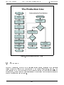
The production line is: on one hand a set of units of manufacturing and assembly, as Building
Stations. On the other hand, there are also test units also referred as, Testing Stations.
Note that a pump can only move to the next step if it passes the tests applied. If the tests
fail, then the pump is sent to the Reworking Station to be repaired. After being repaired,
the pump is returned to take the tests. If no repair is possible, the pump will be sent to the
Recycling Station.
To verify the test results and validate the various stages of testing, all test stations are
connected by Ethernet cable (using the TCP/IP protocol) to a PC server running Windows
Server 2008. This server uses Microsoft SQL Server to manage a database containing all
information about the tests: results, units, time and date they were performed, tolerance
compared with the standard provided in specic cases, etc. Note that the data sent by the
various stations to the server should be in XML to be able to interact with the database.
3/24
Ehouarn Perret
4th Year Internship Report
2. Objectives
The Production Line
Start
Start
Sub-routine for Test Stations
Building
Building
Station
Station11
Start
StartSub-process
Sub-process
Station
Stationreceives
receives
aapump
pump
Building
Building
Station
Station22
Building
Building
Station
Station33
No
Leak
Leak
Test
TestStation
Station
Yes
Packaging
Packaging
Station
Station
Yes
Send
Sendpump
pumptoto
Reworking
ReworkingStation
Station
Electrical
Electrical
Test
TestStation
Station
Functionalities
Functionalities
Test
TestStation
Station
Pump
Pumppass
pass
the
thetest?
test?
Reparable?
Reparable?
No
Send
Sendpump
pumptoto
Recycling
RecyclingStation
Station
Send
Sendpump
pumptoto
Next
Station
Next Station
End
EndProcess
Process
End
EndSub-process
Sub-process
End
End
Figure 2.1: Production Line Flow Chart
2.2 Purposes
During my internship, I worked on an electrical testing station, consisting of an electrical
testing device; the ClareHAL103 manufactured by the British manufacturer, Seaward. The
task entrusted to me was two separate jobs: to design an instrument driver for controlling the
apparatus and, to also provide a graphical interface to control and use the driver eectively in
order to communicate with the server.
4/24
Ehouarn Perret
4th Year Internship Report
2. Objectives
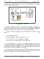
In fact, the pumps should be tested one by one by an operator assigned to this position
regarding the following architecture:
Operator
Client PC
Server PC
Ethernet cable
TCP/IP
Microsoft SQL Server
Webservices
Database
Bar-code
Scanner
Clare HAL 103
Electrical Test Station
Figure 2.2: System Architecture
Regarding the placement, note that I did not have any explanation on the reasons for
dierent types of tests applied to the pumps for reasons of condentiality. Therefore, I will
focus more on the driver to communicate with the device and on the treatment of related data
in response to the report, which was the heart of my subject for this course.
The various meetings and discussions held with the client resulted in the following specications:
• Easy to use, intuitive interface
• Standalone installation (without buying a license LabVIEW)
• Communication with the database (pre-test and post-test)
• Management of communication errors (eg device unresponsive)
To test the operation of the HAL 103, I had at my disposal, a plate connected to ground, so
that all measurements were accurate, using the above probe. I could also simulate a bad test
by exceeding the limits set in the sequence by removing the probe during the measurements,
which signicantly increased the resistance measurement. Several series of tests, with pass or
fail, were conducted to test the reliability of my software.
In the next section, the development methodology is outlined for this specic project as well
as the specications and the steps for development. But rst and foremost, the specic tools
[hardware / software] used during this placement will be explained.
5/24
Ehouarn Perret
4th Year Internship Report
3. Tools
3 Tools
3.1 ClareHAL 103
The Clare Hal 103 Safety Electrical Tester is a powerful tool to assist in the analysis of the
safety of electrical and electronic equipment. Many tests are provided with a wide range of
innovative features to aid dicult test situations, which allow the testing of a wide variety of
equipment.
The Tester is designed to be easy to use, and also includes the following innovative features
(non-exhaustive list):
• Universal Supply Input
• Highly accurate Ground Bond, Hipot leakage and DC IR measurements
• Large Full graphics display, Real-time clock
• Remote mode connecting to PC, port serial COMM, RS232
• Auto testcode generation
• Fully isolated test outputs, to comply with EN50191(a new European standard provides
guidance on how to carry out safety testing in a variety of environments.)
The device is designed to perform the 3 mains following tests:
•
Insulation Test:
•
Hipot Test:
•
Insulation Ground (Earth) Bond Test:
this test is used to verify that adequate insulation exists between the
mains supply pins and ground. During the insulation, a HV DC voltage is applied between
the earth pin and both the live and neutral pins of the Product mains supply plug. The
tester displays the resistance measured and allows the user to conrm sucient insulation
exists.
this test is used to determine that the insulation is of sucient strength
to prevent breakdown, particularly where high transient voltages are likely. During this
kind of test a voltage of 3kV AC RMS is applied between the Hipot probe tip and the
live and neutral pins of the Product mains supply plug.
Insulation Ground Bond Test: this test is to
ensure that the connection between the earth pin in the mains plug of the appliance and
the metal casing of the appliance is satisfactory and of suciently low resistance. When
the test is running, an AC voltage and the test current is applied between the earth pin
of the mains supply plug and the ground bond test lead clip/probe.
6/24
Ehouarn Perret
4th Year Internship Report
3. Tools
3.2 LabVIEW
The choice for using LabVIEW was natural choice, because as stated in the opening of the
report, the fact that National Instruments is a privileged partner of ELCOM, indicates that
most of their system/software developments (about 99 %) are using LabVIEW or using other
related products from National Instruments.
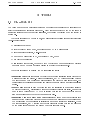
For the developer, a program in G language is a diagram chart, linked together using dierent
icons connected by colored wires. Each wire symbolizes the passage of data from the source it
leaves (as a result) to a target when it arrives (as a parameter).
Therefore, diagrams of the G language have a meaning quite dierent in comparison to
electronic schematics. In a LabVIEW block diagram, the data is transmitted in the wire
ONLY when it is generated by the icon source. The target icon will start its execution when
all its input data becomes available.
This model, for scheduling data ow, determines the execution order of the treatment
program. An important consequence of this rule is that treatments that do NOT exchange
data are free to run in parallel. This property of language G facilitates the development of
multi-threaded applications, particularly useful in the control of reactive systems (embedded
or not).
Program design language G retains an essential procedure. Combined with the performance
of data ow, this approach gives good results in the eld of instrumentation. It is also the most
intuitive for engineers and researchers often more familiar with experimental protocols than
with computer concepts.
This dual, front panel - block diagram allows the programmer to easily and distinctly
separate between the graphical user interface and measurements process (and more generally the
information processing / calculations, etc). It is therefore, a very powerful tool/programming
language to quickly create GUI programs and computers, even for people who have no computer
background.
Figure 3.1: LabVIEW sample Program
7/24
Ehouarn Perret
4th Year Internship Report
3. Tools
As can be seen from the Figure 2.3 above, the front panel allows a user to design GUI: here
we simply display the inputs x and y and the output x + y. Concerning the Block Diagram
is used to do calculation, programming [here a simple addition x + y ] like signal processing,
communication with the hardware, etc.
3.3 XML Language and Webservices
XML stands for Extensible Markup Language. "Extensible Markup Language" is a markup
language derived from the SGML generic (which is another well-known, very traditional markup
language). This syntax is called 'extensible' because it allows the denition of dierent name
paces (I.E. - languages with their own vocabulary and grammar, such as XHTML, XSLT, RSS,
etc.).
With tools and languages associated an XML application is generally consistent with certain
principles:
• the structure of an XML document is dened and validated by a schema
• an XML document is completely transformed into another XML document.
XML code snippet
1 − <Test Name = " ID_UltimateTest ">
2
<TestStartTime>2011/07/13 22 : 0 5 : 3 5</ TestStartTime>
3
<ExecutionTime>9 3 . 8 7</ ExecutionTime>
4
<Count>2</Count>
5
<S t a t u s>F a i l e d</ S t a t u s>
6
7
− <R e s u l t s>
8
− <R e s u l t Name = " Test no1 ">
9
<S t a t u s>Passed</ S t a t u s>
10
<Measurement>4 5 . 0 4 3 9 4 5</ Measurement>
11
<U n i t s>mOhms</ U n i t s>
12
<Test_Type>"DC Hipot "</Test_Type>
13
<Limit_Low>1 . 0 0 0 0 0 0</Limit_Low>
14
<Limit_High>7 0 . 0 0 0 0 0 0</ Limit_High>
15
</ R e s u l t>
16
− <R e s u l t Name = " Test no2 ">
17
<S t a t u s>F a i l e d</ S t a t u s>
18
<Measurement>5 0 . 4 6 5 4</ Measurement>
19
<U n i t s>mOhms</ U n i t s>
20
<Test_Type>"DC Hipot "</Test_Type>
21
<Limit_Low>0 . 0 0 0 0 0 0</Limit_Low>
22
<Limit_High>4 0 . 0 0 0 0 0 0</ Limit_High>
23
</ R e s u l t>
24
<R e s u l t s>
25
</ Test>
8/24
Ehouarn Perret
4th Year Internship Report
3. Tools
As shown above, in the example XML, that process is used to send dierent information,
resulting from electrical testing web-services and to save them in the database.
A web service (or service toile1) is a computer program that allows communication and
exchange of data between heterogeneous systems and applications in distributed environments.
It is therefore; a set of functionalities exposed on the Internet or an Intranet, by and for
applications or machines, without human intervention, and stays synchronous. A Web service
is also a software component identied by a URI, whose public interfaces are dened and called
XML.
Its denition can be discovered by other software systems. Web services can interact with
each other in a manner prescribed by its denition, using XML messages carried by the Internet
protocols.
As part of my project, using XML and web services were relatively transparent. In fact,
LabVIEW had a module to automatically create all the necessary functions to send and receive
data via the web-service.
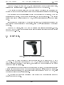
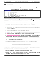
3.4 HHP 3800g
Figure 3.2: The HHP 3800g Barcode Scanner
Honeywell HHP 3800g produces the barcode scanner used, and it connects to a PC via a
USB cable. As this device has been used by ELCOM, to use for the platform leak test, the
driver to control it has already been created, and it reads the bar code present on the pumps
to see what tests are applicable.
If the serial number does not exist or the previous test was faulty, the driver returns an error
message that says to send the pump to the reworking station and testing cannot be performed.
If all conditions are satised, the appropriate tests will be performed on the HAL 103, using
the driver developed during this internship.
So, the driver for this device has already been achieved and the integration within the
project has been very quick.
9/24
Ehouarn Perret
4th Year Internship Report
4. Project
4 Project Management
4.1 Software Development Model
To manage this project, I relied on a well-known design pattern in the software development
world: the famous V Model. This V model is a well-known method of organization that dates
far back to the industry and has been adapted to computers in as early as the 80s. This model
is still relevant, even if not necessarily suited to projects where developments and changes of
direction are frequent because almost all the theory is set before starting the project. (See
below for the structure of the simplied V Model.)
The V Model
Time
Ongoing
Support
Review / Test
Specifications
High Level
Design
Operational
Testing
Integration
Testing
Details
Low Level
Design
Unit
Testing
Coding
Figure 4.1: The V Model Structure
We can distinguish three main parts: the design phase, implementation phase (coding) and
the validation phase. Phases of design and validation are cut into several parts. Each step can
only be achieved once the previous step is completed, which reduces the risk of failure on the
project.
10/24
Ehouarn Perret
4th Year Internship Report
4. Project
Below are the denitions of dierent stages of the V Cycle Model:
•
Specications:
•
High Level Design:
•
Low Level Design:
•
Coding:
•
Unit Testing:
•
Integration Testing:
•
Operational Testing:
They have already, more or less, been explained in Part 2. To summarize,
this is the criterion that must be met for the software implementation when the project
is completed to meet all customer requirements.
The phase of design of computer architecture and software architecture can also be referred to as high-level design. The baseline in selecting the architecture
is that it should recognize each item on the list, consisting of modules, brief functionality
of each module, their interface relationships, dependencies, database tables, architecture
diagrams, technology details etc. The integration testing design is carried out in this
particular phase.
Low Level Design: The designed system is broken up into smaller
units or modules and each of them is explained, so that the programmer can start coding
directly. The low-level design document, or program specications, will contain a detailed
functional logic of the module, in pseudo-code.
This is the implementation of the modules that have been previously dened.
This is the method by which individual units of source code are tested to
determine if they are t for use. A unit is the smallest testable part of an application. In
procedural programming, a unit may be an individual function or procedure. Unit tests
are created by programmers or occasionally by white box testers. The purpose is to verify
the internal logic code by testing every possible branch within the function, also known as
test coverage. Static analysis tools are used to facilitate in this process, where variations
of input data are passed to the function to test every possible case of execution.
The separate modules will be tested together to expose faults in
the interfaces and in the interaction between integrated components. Testing is usually
done with the black box, as the code is not directly checked for errors.
Compare the system specications against the actual system.
After the integration test is completed, the next test is the system test. System testing
checks if the integrated product meets the specied requirements. Why is this still necessary after the component and integration tests? The reasons for this are as follows: In
the lower test levels, the testing was done against technical specications, (I.E. - From
the technical perspective of the software producer). The systems test, though, looks at
the system from the perspective of the customer and the future user. The test validates
whether the requirements are completely and appropriately met.
Example: The customer (who has ordered and paid for the system) and the user (who
uses the system) can be dierent groups of people or organizations with their own specic
interests and requirements of the system. Many function and system characteristics result
from the interaction of all system components. Consequently, they are only visible on the
level of the entire system and can only be observed and tested there.
•
Ongoing Support: This is the last phase which is to provide technical support once the
product is nished and delivered to the customer, depending on the contract duration is
shorter or longer in some cases and may need an additional payment from the customer,
as in part of an extended warranty.
11/24
Ehouarn Perret
4th Year Internship Report
Year
2011
Month
Week
4. Project
May
20
21
June
22
23
24
25
July
26
27
28
29
August
30
31
32
LabVIEW Training
Specications
High Level Design
Low Level Design
Coding
Unit Tests
Integration Tests
Operational Tests
Writting User Manual
Writing the Report
Figure 4.2: The provisional Gantt Chart
4.2 Provisional Chart
Thus by the denition of the V Cycle, I was able to draw a Gantt chart that shows the tasks
performed during the weeks of the internship. The dierences between the Gantt chart diagram
and the original tasks, will be seen further in the report. Otherwise, this diagram allowed me
to:
Otherwise, this diagram allowed me to:
• determine the dates of a project
• identify existing margins on certain tasks
• view at a glance or delay progress.
12/24
Ehouarn Perret
4th Year Internship Report
5. Development
5 Development
5.1 Protocol Basics
5.1.1
Description
The Remote Command Protocol is an RS232 protocol that allows Clare tests to be done reliably
and quickly congured from a remote host and also allows the remote host to send commands
to the instrument in order for the system to automatically perform electrical tests.
The protocol is based on an ASCII-HEX notation. That is, every byte of data is coded using
two hex digits in the range 0 through 9, and, A through F. Upper case ASCII hex must be used
throughout the process. This is a common notation that allows easy detection of corrupted
characters, and avoids the need for special encoding of control characters etc.
5.1.2
Initialization
Connection settings are the following:
• Baudrate: 9600
• Data Bits: 8
• Parity: None
• Stop Bits: 1.0
• Flow Control: XON/XOFF
• Timeout(ms): 1000
• Termination Character: Carriage Return = 0x0D in HEX
I have added a step for ushing (clear) the memory before it can communicate with a device
and initialize properly between the PC and the HAL 103.
The result of the initialization in LabVIEW is very fast and easy to implement as part of the
serial link, b simply using the tools provided by adapting the parameters of the communication
data provided in the user manual.
It has also added a step to prevent the ush of the "remnants" from initializing the connection disrupts communication between the PC and the HAL 103.
13/24
Ehouarn Perret
4th Year Internship Report
5. Development
Note that in that case the inputs and outputs are:
• serial port COMM 1 or 2 which is connected to the RS232 cable
• the error stream to see if there was a problem connection, for example using the timeout
if no value is read during the interval (1000 ms), so an error is generated.
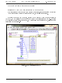
Note also the icon at the top right, specic to the program (vi is the le extension of
LabVIEW, so we will link it to other boxes to create the overall program; the sub-vi course
may also use other (sub)sub-vi and so on). By customizing the icons for each vi, allows a better
readability of the program.
Figure 5.1: The Initialization subvi
14/24
Ehouarn Perret
5.1.3
4th Year Internship Report
5. Development
Formatting Requests and Responses
Requests from the host are formatted as follows:
•
<cmdseq>Two ASCII HEX digits for an ever-incrementing command sequence number.
A host should increment it's command sequence number before transmitting a command
(but not when transmitting retries of the same command). The sequence number is
copied to all responses generated. If the tester receives a command with a command
sequence number the same as that for the previously correctly decoded command, then
the tester simply re-sends its last response without performing any action this deals
with the situation where an ACK/NAK/InterimACK is corrupted before being received
by the host.
•
<cmd>Two ASCII HEX digits representing the required command code.
•
<instance>Two ASCII HEX digits indicating the particular item instance (0 through
N). For many protocol commands the item instance number is not relevant and must be
set to zero.
•
<datasz>FourASCII HEX digits indicating number of encoded data bytes in the request.
Many protocol commands to not require any data to be supplied from the host, in which
case the data size must be zero.
•
<data>ASCII
•
<crc16>Four
HEX representation of the data for commands that required strings,
values, or structures.
ASCII HEX digits representing the 16-bit CRC of all encoded bytes up
to, but not including the CRC value itself.
Responses from the tester take the following form:
•
<cmdseq> TwoASCII HEX digits representing the command sequence number received
from the host in the command to which this response relates.
•
<response>
terim ACK).
•
<datasz>
response.
•
Two ASCII HEX digits representing the response code (ACK, NAK, in-
Four ASCII HEX digits indicating number of encoded data bytes in the
<data> ASCII HEX representation of the NAK reason code (for NAK response code),
contents, or the requested data (for ACK or interim ACK response codes). Some ACKs
and interim ACKs do not return any data, in which case <datasz> will be zero.
•
<crc16> Four ASCII HEX digits representing the 16-bit CRC of all encoded bytes up
to, but not including the CRC. Note that if the host includes the CRC value within the
CRC calculation, then the result will always be zero for uncorrupted data.
15/24
Ehouarn Perret
5.1.4
4th Year Internship Report
5. Development
Start Session
Then in order to send the desired commands, open a session through the session start, the data
required which is able to be basically translated into the following C code:
Data for Session Start Command translated in C language
struct _ s s s c m d d a t a _ s e s s i o n _ s t a r t
1 typedef
2 {
3
u8 p r o t o c o l _ v e r ;
4
u8 baud_code ;
5
u8 password_seed ;
6
u8 password [ARRAYSZ_SSS_PASSWORD ] ;
7 } ssscmddata_session_start ;
Reminder: u stands for unsigned integer, u8 is 2 HEX ASCII characters, u16 is 4 HEX ASCII
characters and here a oat type is representation by 8 ASCII HEX characters.
The analysis of construction for string commands at a start session will also allow us to
understand how they are built for the requests strings for the HAL 103.
Thus it is sucient to concatenate the following pieces of ASCII HEX string:
•
01:
•
10:
•
00 00:
•
000E: the datasz, simply calculated by LabVIEW after parsing the string
•
000000000000000000000000000:
According to the denition we gave before for the
data, and as the client did not want management password, it is a simple sequence of 0
•
0278:
the cmdseq, it is logical cause it is the rst command sent to the device before to
perform any operation
the cmd code to indicate that is a start session command
the item id and the instance, in the case of a start command both are to set to 0
This is the CRC16 calculated by the standard method for Telecommunications
(CCIT), it is used to verify data integrity.
Therefore to start a session it is enough to send the HAL 103 the following string:
01100000000E0000000000000000000000000000278
AND to read the appropriate answer sent by the HAL103 to the PC. To be correct the string
must verify the following conditions in this start session case:
• cmdseq = 0x01, must be the same sequence number than the request
• response code = 0x01 matching to SSSRSP ACK FINAL means that the command is
successfully received and completely processed by the tester.
16/24
Ehouarn Perret
4th Year Internship Report
5. Development
• datasize must t to data eld received
• the CRC16 must match to the rest of the string
So if the start session is successfully processed we should read the following string:
01010000C544
Of course we must pay attention to the presence of carriage return at the end of the string
using parsing to only compare the "true" strings themselves.
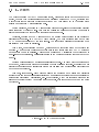
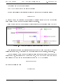
Below a basic example of one possible implementation for the connection using LabVIEW
Figure 5.2: A basic start session implementation using LabVIEW
This principle of sending and verifying is used each time you send commands to the same
session 'stop' command, which allows you to properly close the open session, if necessary.
To stop a session we need to send the following string for example (cause it depends on the
sequence number, here it's for the 4th send command, by the way the command code for the
stop session is 11 and 0 for the others elds except for the CRC16 of course):
041100000000A6BA
and reads the following one:
040100007901
17/24
Ehouarn Perret
4th Year Internship Report
5. Development
5.2 Download Test Sequences
After starting session the driver must download the names of test sequences and the corresponding code. This is the code test that contains all the required information (type of test,
limits, etc.) to perform the test.
Characteristics of the command to download test sequences:
• cmd code = 0x20
• item id = 0x25
• instance from 0x00 to 0x14 (20 in Decimal)
Requests to download the HAL 103 send responses in the data eld containing information
regarding the name and ID code for testing.
The algorithm is not very complicated it consists in incrementing the instance as the same
way as it increments the cmdseq so through the 20 tests available in the device, then analyse
the responses strings and parse them to store in a table including the names and the ID code
tests. This download is done once the launch of the instrument driver. In fact if you want to
manually add another test you must rst exit the remote mode, so every time driver is running
the test sequences available are updated.
The Seaward Test codes are an 11-character string where each character is in the ASCII
range 0 to 9 and A to Z. The character count starts from left to right. The example below
shows Z as digit 1 or (character no. 1) and the integer 1 as digit 2 (character no. 2) and so on.
e.g. Z1234567890
5.3 Perform the HAL Tests
Characteristics of the command to perform HAL Test:
Command Code = 0x80
Item id =
• SSSID HAL TEST TYPE HIPOT 50 = 0x01
• SSSID HAL TEST TYPE HIPOT 60 = 0x02
• SSSID HAL TEST TYPE HIPOT DC = 0x03
• SSSID HAL TEST TYPE DCIR = 0x04
• SSSID HAL TEST TYPE EBOND 50 = 0x05
18/24
Ehouarn Perret
4th Year Internship Report
5. Development
• SSSID HAL TEST TYPE EBOND 60 = 0x06
Instance = 0x00
About data, referring to the HAL103 Manual including tables I was able to create a converter
following the dierent code received
5.4 Store Data in Database
As I mentioned in Part 3 communicating with the database via webservice and xml is simply
entering the IP address of ethernet server in LabVIEW. It then automatically generates the
necessary vi communication and data management.
19/24
Ehouarn Perret
4th Year Internship Report
6. Results
6 Results
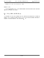
6.1 Achievement
At the end of the internship I managed to carry out the program requested by the customer,
according to plan before with some dierences.
The application has also been transformed into an executable that requires no license for
the LabVIEW client (but it can not see the source code). It can be run on any machine
with Windows if it has the appropriate runtimes that are provided free of charge at National
Instruments.
We tested several scenarios such as the disconnection of some devices (including the connection to the server) or tests that do not exist in order to ensure all possible cases of use. The
tests were passed and the client was satised with my achievement that met the specications
initially provided.
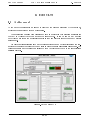
Figure 6.1: The Driver GUI
20/24
Ehouarn Perret
4th Year Internship Report
Year
2011
Month
Week
6. Results
May
20
21
June
22
23
24
25
July
26
27
28
29
August
30
31
32
LabVIEW Training
Specications
High Level Design
Coding
Integration Tests
Operational Tests
Writting User Manual
Writing the Report
Figure 6.2: The Final Gantt Chart
6.2 Diculties Encountered
Finally it turned out that the low level design, coding and unit testing were done at the same
that's why I met with the same name as it often happened that the unit tests reveal low as I
corrected direct encoding, so I can only assume that the segregation of duties were a little too
strong in the V-model and this have made me lose a little time. Indeed it was not best suited
to the particular situation, because the design time should have been longer. He might have
had to use another method such as AGILE method is more responsive and has to deliver more
regular.
Another major diculty in this course was the documentation of the device which contained
many gaps. I had to repeatedly contact support Seaward who sometimes struggle to answer.
Sometimes the information given in the manual were completely wrong
In fact the support service does not really know the remote control part because it was
created by another company that no longer exists so it was very dicult to nd all the answers
I was looking for. I nally managed to get out in force to hack and I was able to help improve
the user manual and documentation of the device.
21/24
Ehouarn Perret
4th Year Internship Report
6. Results
Finally, the entire measurement process can be summarized with the diagram below:
The HAL Test Process
(in normal operation)
Start
Start
Download
Download
Tests
TestsSequences
Sequences
(in abnormal operation...)
Conditions
Conditionstotostart
start
the
thetest
testare
areOK?
OK?
Bar
Barcode
codeexists?
exists?
Previous
PreviousTest
TestisisPass?
Pass?
Scan
Scan
Bar
BarCode
Code
Get
GetInformation
Information
from
fromServer
Server
Get
GetTest
TestName
Name
Devices
Devicesconnected?
connected?
Measurement
Measurementwithin
withinlimits?
limits?
Perform
Perform
HAL
HALTest
Test
Get
GetResults
Results
From
FromHAL
HAL103
103
Send
SendResults
Results
totoServer
Server
Handle
Handleand
andDisplay
Display
Error(s)
Error(s)
End
End
Figure 6.3: The HAL Test Process
22/24
Ehouarn Perret
4th Year Internship Report
7. Conclusions
7 Conclusions
7.1 Professional Assessment
This internship allowed me to improve myself in many areas, such as practicing English in a
professional environment, such as in an international context where I had to plan meetings
between two dierent nationalities. In a technical point of view, I also widened my knowledge
about the use of LabVIEW, the graphical development platform.
At rst it seemed particularly stark because I was more used to developing/programming
with languages like C++ and Java using the instructions as texts. However, the methodology
using LabVIEW also has its advantages, such as a better readability of programs, which increase
the understanding of the programs and therefore induce better re-usage with other projects.
In addition, LabVIEW included many tools for programming, both low and high levels,
much like the communication driver, which allows minimal development time and provide more
interaction with the client in a project.
Furthermore, it is possible to achieve large-scale projects without requiring that the customer have a license with LabVIEW. Compiling, just like the C language, is an executable with
the necessary runtimes and its proper functions (but it is a free download for anyone).
The language G, from National Instruments, has become an industrial standard for measurements and instrumentation. Having been part of a major project within ELCOM's partner,
the creator of LabVIEW, allowed me access to a great learning experience at the professional
level and be of great benet for my potential international career.
This internship also allowed me to have a rst person inside view of what is used in large
industrial projects and to learn XML.
Finally, to get involved in a big project from scratch: from the specications to the endproduct through the design phase, was very rewarding on every point, including teamwork,
management and even just being in an international study.
23/24
Ehouarn Perret
4th Year Internship Report
7. Conclusions
7.2 Personal Assessment
This internship allowed me to discover a new culture of the Czech Republic. I had a lot of
prejudice going there initially, but they all proved unfounded. In fact most people who saw me
from there, saw an evil eye and I think it's a misunderstanding.
Indeed, far from the clichés of the communist era, the Czech Republic is a modern country,
as evidenced by the company where I did my internship, ELCOM. The Czech Republic, in
contrast to France, because it is so committed on improving the level of English for its citizens,
it shows everywhere, both in business and in everyday life.
I have met some great people, both at work and in daily life. The Czechs are very proud
of their country and know how to show it. They know to be very friendly and even if their
English is sometimes rough, they will do everything to help you, even if they have to use sign
language.
This enabled me to broaden my view with others and discover new horizons and new ways
of thinking. Finally this course has given me the desire to go abroad again to guide myself
in my international career, even if my English has not changed much, it is more uent than
before. I now have less fear and am more condent when I approach people abroad.
I think that any engineer should do an internship abroad, because it is what being an
engineer is about; knowledge and understanding of new situations and being open to the world.
24/24
Ehouarn Perret
4th Year Internship Report
DVI Structure
Appendixes
A - DVI Internal Structure
ELCOM DVI Internal Structure
Head of
Directors Board
Jiří Holoubek
CEO
Vladimir Korenc
ELCOM DVI
Division Director
Dr. Daniel Kaminsky
Administration
HR
Business
Development
Jan Šíma
Accounting
Office Management
Special Projects
Marketing
Automated
Test Systems
Michal Harhaj
Sales
Test Systems
Assembly
Machinery Design
Petr Kotek
Vision Systems
Assembly Lines
Power
Quality Systems
Dr. Jiří Hula
Electrical Machines
Software
Components
Jiří Komínek
Electronics and
Electrical Design
Miroslav Rumpel
Instrument Drivers
Applications
Figure 7.1: DVI Internal Structure
A
Ehouarn Perret
4th Year Internship Report
People in Project
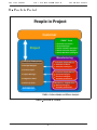
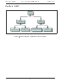
B - People in Project
People in Project
Customer
FMEA* Team
● Customer specialists
● Project Manager
Project
● Senior Software Developer
● Senior Electrical Designer
● Senior Machinery Designer
Manufacturing
Front-End Department
Software Department
● Software Architect
● Concept Designer
● Software Developers
● Domain Expert
Electrical Department
● Electrical Designer
● Project Manager
● Electronic Designer
● Assembly technicians
● Integration Team
Machinery Department
● Power-Up Team
● Machine Designer
● Assembly technicians
ELCOM DVI
*FMEA = Failure Mode and Effects Analysis
Figure 7.2: People in Projects
B
Ehouarn Perret
4th Year Internship Report
Business Project
C - Business Project
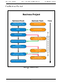
Business Project
Technical Track
Business Track
Requirements, mining
(can include feasibility study)
Offer Submission
Design
Order and Contract
Time
Partial Payment
(typically 30% to 50%)
Implementation / Manufacturing
Qualification
(Factory Acceptance Test)
Partial Payment
(up to 90%)
Delivery, Power-Up
Site Acceptance, Training
Partial Payment
(typically remaining 10%)
Technical Support and Warranty
Figure 7.3: Business Project
C
Project realization period
Design Validation
Ehouarn Perret
4th Year Internship Report
Basic SADT
D - Basic SADT
Perform
Perform
HAL Test
HAL Test
Write
Write
Test Command
Test Command
Init
Init
Communication
Communication
Read
Read
Test Result
Test Result
Set parameters
Set parameters
Into HEX String
Into HEX String
Convert HEX string
Convert HEX string
Into Measurements
Into Measurements
Close
Close
Communication
Communication
Figure 7.4: Basic Structured Analysis and Design Technique
D
E - Examples: Character Equivalences
Figure 7.5: Meaning of the 1st character
Figure 7.6: Meaning of the 2nd character
Figure 7.7: Meanings for the 5st,6th and 7th characters
DOS DU RAPPORT
Année d’étude dans le département : 4
Etudiant (nom et prénom) : Ehouarn Perret
----------------------------------------------------------------------------------------------------------------------------------Entreprise : ELCOM, a.s, Division of Virtual Instrumentation
Adresse complète : Technologická 374/6, 708 00, OSTRAVA
(géographique et postale)
Téléphone (standard) : +420 558 279 902
Télécopie : +420 558 279 901
----------------------------------------------------------------------------------------------------------------------------------Responsable administratif (nom et fonction) : Dr Daniel Kaminsky
Téléphone : +420 558 279 902
Télécopie : +420 558 279 901
Mél : [email protected]
---------------------------------------------------------------------------------------------------------------------------------Maître de stage (nom et fonction) :
Téléphone : +420 558 279 902
Télécopie :+420 558 279 901
Mél : [email protected]
----------------------------------------------------------------------------------------------------------------------------------Tuteur enseignant (nom et fonction) : Irfan Ahmad
Téléphone : + 33 (0)4 76 82 63 28
Télécopie : + 33 (0)4 76 82 63 88
Mél : [email protected]
----------------------------------------------------------------------------------------------------------------------------------Titre : (maximum 2 à 3 lignes).
Conception et Réalisation d’un driver pour le HAL 103
Résumé : (minimum 15 lignes).
Dans le cadre de ma quatrième année à Polytech’ Grenoble au sein du
Département Informatique Industrielle et Instrumentation j'ai fait un stage à
l'étranger pour apprendre à m’adapter à de nouvelles situations et à utiliser mon
anglais dans un contexte professionnel. L'objectif de ce stage était de créer un
driver d'instrumentation autour du développement d'une plateforme de test basé
sur appareil de tests électriques: les HAL 103.
Ceci s’est déroulé au sein de l’entreprise ELCOM. Avec Michal Harhaj mon
superviseur en entreprise et Irfan Ahmad mon superviseur école, j'ai conçu et
construit le pilote de la HAL103 afin d'interagir avec une base de données pour
stocker les données de mesure. Le HAL 103 est un appareil de tests électriques très
haute tension, il est utilisé par exemple pour détecter les fuites de courant. Nous
étudierons d’abord dans ce rapport une brève description des conditions entourant
ce stage et ensuite les différentes étapes de la conception en utilisant le concept de
gestion de projet et la mise en œuvre (principalement en LabVIEW) qui a conduit
à la réussite de ce projet. Enfin, je remercie toute l’équipe d’ELCOM de m’avoir
donner tant de confiance et de m’avoir laissé carte blanche pour mener à bien ce
projet avec une entière autonomie dans la relation client que cela supposait.
1