1
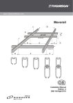
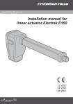
Movorail
Service Manual
Edition: 2
DW110419gb-0508
Movorail
Version History
Edition Number
1
2
FEBRUARY 2005
Edition Date
n.a.
2005-02-21
THOMSON
Reason for Revision
Manual created
Product changes
DANAHER MOTION is a registered trademark of Danaher Corporation. Danaher Motion makes every
attempt to ensure accuracy and reliability of the specifications in this publication. Specifications are subject
to change without notice. Danaher Motion provides this information "AS IS" and disclaims all warranties,
express or implied, including, but not limited to, implied warranties of merchantability and fitness for a
particular purpose. It is the responsibility of the product user to determine the suitability of this product for a
specific application.
©2005 Danaher - Printed in Sweden. All rights reserved.
2
DW110419gb-0508 Edition: 2
Service Manual
Movorail
FEBRUARY 2005
THOMSON
Table of contents
1. Introduction ...............................................................................................................4
2. Inspection and service intervals ..............................................................................4
3. Inspection and service of the Movorail system ......................................................5
3.1
Rails type SPR and distance girders type DNS and SD......................................................... 5
3.2
Connections type SK............................................................................................................... 5
3.3
General about suspensions .................................................................................................... 6
3.4
Inspection of suspension type DZ, VBKLA, DBSU and ASU.................................................. 6
3.5
Safety cables for suspensions type SLU ................................................................................ 7
3.6
Flexible bolt connections for trolleys type BUB....................................................................... 7
3.7
Flexible bolt connections for trolleys type TBUB..................................................................... 8
3.8
Safety cables for trolleys type SLV ......................................................................................... 8
3.9
End plates type TPL, end stops type STP and end plate supports type EPF ........................ 9
3.10 Walter bolts type WBM........................................................................................................... 9
3.11 Crab trolleys type LPV and bogie trolleys type BGV............................................................. 10
3.12 Cable trolleys type KBV, KBVA and KBVS, rail and trolley cable attachements
type KFFB, KFKK, KFVS and KFSB and motion limiters type BGR.................................... 10
3.13 Pick up trolleys type STV5 and STVG5 ................................................................................ 11
3.14 Crane distance trolleys type TTDS ....................................................................................... 11
3.15 General about motor trolleys type TMV ................................................................................ 12
3.16 Replacement of drive wheel on motor trolley type TMV ....................................................... 12
3.17 Adjustment of drive wheel contact pressure on motor trolley type TMV............................... 13
3.18 Current track type SB and related components .................................................................... 13
3.19 Yokes type TBO .................................................................................................................... 14
3.20 Switches type HXL and VXL and turntables type VSL ......................................................... 14
3.21 Tightening torque for bolts .................................................................................................... 15
Service Manual
DW110419gb-0508 Edition: 2
3
Movorail
FEBRUARY 2005
THOMSON
1. Introduction
Thomson Movorail is a rail system made of extruded aluminium profiles for loads up to 600 kg, designed and
manufactured by Danaher Motion in Kristianstad, Sweden to meet the latest national and international
standards. Product quality is assured by our ISO 9001 certified quality system.
Read this manual and carefully study the instructions and documents supplied with the components before
you start working to ensure that the service is carried out in a safe and simple manner.
Never hesitate to contact Danaher Motion for further information.
Important!
• Read through this service manual and all other diagrams and documents supplied with the shipment before starting any
service work and follow all applicable instructions inside to guarantee that the service is carried out in a safe manner.
• Never walk or stand under a hanging load.
• Ensure that all ladders, lifting and climbing aids used during service are in good condition and that they are securely fastened.
• Make sure that only authorised personnel enter the working area.
• Never use any components that appear to be faulty or damaged. Replace them immediately with components of the same
make and type.
• Never work with the electrical power or the compressed air switched on.
• Do not hesitate to contact Danaher Motion if you have any questions.
2. Inspection and service intervals
Movorail must, like all lifting systems, be serviced and inspected. The service intervals depends on how
frequently the equipment is being used, see the table below. For the service of equipment manufactured by
other companies that can be a part of the system, such as hoists, lifting loops and other lifting devices, we
recommend you to see the instructions from respectively manufacturer.
When the service and inspection is carried out all points in this manual, which is applicable to the system
in question, should be inspected. Furthermore a general visual inspection should be carried out of the entire
system.
In addition to the recurrent service and inspection a visual inspection should be done before the system is
used. All parts which then seems damaged or faulty should immediately be checked, repaired or replaced.
Never perform any service work with the power on!
Recommended service intervals*
Operation time
Service interval
> 16 h/day
1 week
6 – 16 h/day
2 weeks
2 – 6 h/day
4 weeks
1 – 2 h/day
8 weeks
< 1 h/day
12 weeks
* according to SS 768 00 04
Table 1: recommended service intervals
4
DW110419gb-0508 Edition: 2
Service Manual
Movorail
FEBRUARY 2005
THOMSON
3. Inspection and service of the Movorail system
3.1 Rails type SPR and distance girders type DNS and SD
Figure 1: inspection of rails
1. Check so that the rails are not deformed. Replace a damaged rail.
2. Check the parallelism of the rails if the system consists of parallel rails in any direction. The distance L
must not deviate more than ± 2 mm along the entire length of the rail. Adjust if needed.
3. The distance between the trolleys (a) in parallel rails should be the same as between the rails. The
distance between the trolleys can be adjusted by loosening the flexible bolt connection type BUB (b)
(see point 3.6) so that the trolley can be moved. Note! Do not forget to re-tighten the BUB after the
adjustment. Test the system after the adjustment.
4. If the system is equipped with rigid or flexible distance girders (c) the tightening torque of the bolts shall
be checked. For correct tightening torque, see the table in point 3.21.
5. If the rails consist of SPR 295W (a rail with a welded reinforcement profile) the welding (d) between the
rail and the reinforcement profile should be checked with respect to crack indications. At indication of
cracks, replace the rail(s) in question.
6. Check so that the system is clearly marked with one or several max. load signs.
3.2 Connection type SK
Figure 2: inspection of connections
1. Check so that the rails have not moved apart (a). Adjust if needed.
2. Check that the connection is located at the centre of the joint (b) and that the tightening torque is correct
for all bolts. Adjust, complete or tighten if needed. For the correct tightening torque, see the table in
point 3.21.
3. Check that the locating pins (c) on both sides of the rail joint are in position and are fixed with glue in
one of the rails. If they are loose, use a glue of type Omni-Fit 200M, Loctite Multibond or any other
equivalent glue.
4. Check at curve connections that the rail and the curve have not moved apart (d). Adjust if needed.
Service Manual
DW110419gb-0508 Edition: 2
5
Movorail
FEBRUARY 2005
THOMSON
3.3 General about suspensions
Figure 3: suspensions
All rails must be installed horizontally with an accuracy of ± 2 mm irrespective off the distance between the
suspension points. Adjust if needed.
3.4 Inspection of suspensions type DZ, VBKLA, DBSU and ASU
Figure 4: inspection of suspensions
1. For suspensions of type DZ, check so that the attachment bolts (a) are correctly fastened and that the
T-slot bolts (b) are correctly tightened. See table in point 3.21.
2. For suspensions of type VBKLA, check so that the T-slot bolts for the clamps (c) are correctly tightened.
See table in point 3.21. Also check so that the T-slot bolts are placed as close to the girder as possible (d).
3. For suspensions of type DBSU, check so that the T-slot bolts for the clamps (e) are correctly tightened.
See table in point 3.21. Also check so that the T-slot bolts are placed as close to the girder as possible
(f) and that the pin (g) is intact and is equipped with a split cotter pin.
4. For suspensions of type ASU, check so that the T-slot bolts for the clamps (h) are correctly tightened.
See table in point 3.21. Also check so that the T-slot bolts are placed as close to the girder as possible
(i) and that the attachment plates and the adjustment bolts are intact and correctly tightened (j).
6
DW110419gb-0508 Edition: 2
Service Manual
Movorail
FEBRUARY 2005
THOMSON
3.5 Safety cables for suspensions type SLU
Figure 5: safety cable for suspensions
Some systems are equipped with safety cables for suspensions to enhance the safety. Safety cables shall
be inspected as described below. Note that a safety cable that has been exposed to a chock load
immediately must be replaced.
Check at an safety cable inspection that:
1. the correct cable diameter is being used (ø 4 mm for SPR 85, ø 6 mm for all other rails).
2. the cable locks (a) are intact and that their positions are correct.
3. the cable is not slack.
4. the cable is not damaged.
3.6 Flexible bolt connections for trolleys type BUB
Figure 6: flexible bolt connection for trolleys type BUB
The flexible bolt connection for trolleys type BUB connects bogie trolleys to crane rails. A BUB is inspected
as follows.
1. Check the tightening torque of the bolt. For the correct tightening torque, see table in point 3.21.
2. Check so that a split cotter pin is installed in the hole (a) in the bolt.
3. Check so that it is not possible to move the lower thick washer (c). Replace the BUB if it is possible to
move the washer.
4. Check that the bolt is not bend or worn. Replace the BUB If it is bend or worn.
5. Check that the trolley and the rail are not locked in relation to each other, i.e. the connection may not be
rigid. A rigid connection indicates a faulty installation and the BUB shall be replaced.
6. Check at the inspection or replacement of a BUB that the chamfer of the upper (b) and the lower washer
(c) is positioned correctly. For BUB 85 the chamfer should point up on both washers. For BUB 125/160A
the chamfers should point down for the upper washer and point up for the lower washer.
Service Manual
DW110419gb-0508 Edition: 2
7
Movorail
FEBRUARY 2005
THOMSON
3.7 Flexible bolt connections for trolleys type TBUB
Figure 7: flexible bolt connection for trolleys type TBUB
The flexible bolt connection for trolleys type TBUB connects bogie trolleys to crane rails. A TBUB is
inspected as follows.
1. Check the tightening torque of the bolt. For the correct tightening torque, see table in point 3.21.
2. Check so that the TBUB is not damaged. Replace any damaged TBUB.
3.8 Safety cables for trolleys type SLV
Figure 8: safety cables for trolleys
Safety cables for trolleys shall be installed at every BUB to enhance the safety. Immediately install a safety
cable if one is missing. The cables comes in two sizes, SLV4 (ø 4 mm) for rail SPR 85 and SLV6 (ø 6 mm)
for rails SPR 125, SPR160A, SPR295B and SPR 295W. Both are installed in the same way.
1. The safety cable type SLV (b) is installed trough the trolley (a) and secured with two T-slot bolts (c) in
the crane rail (d).
2. Check at safety cable inspection: that the correct cable size is being used, that the T-slot bolts of the
cable is correctly tightened (see table in point 3.21) and that the cable is not jammed or damaged.
3. A safety cable for trolleys should immediately be replaced if it has been exposed to a chock load.
8
DW110419gb-0508 Edition: 2
Service Manual
Movorail
FEBRUARY 2005
THOMSON
3.9 End plates type TPL, end stops type STP and end plate supports type EPF
Figure 9: end plates, end stops and end plate supports
End plates (a) and end stops (b) are installed in the rail ends of the system. An end stop must be installed in
any end missing an end stop. If the end stop is not installed in outermost part of the end an end plate
support (c) can be installed so that the end plate can be attached.
1. All bolts shall be tightened according to the table in point 3.21. The bolts have to be re-tightened after
some time of operation.
2. Check so that the end stop has not moved out of position in the rail.
3. Check so that the rubber bumper is intact. Replace the end stop if the rubber has become friable or
worn.
3.10 Walter bolts type WBM
Figure 10: Walter bolt
Walter bolts (a) are optional and consists of a bolt, which is installed trough, the Movorail profile in order to
secure the position of the end stop. If Walter bolts are installed, inspect them as described below.
1. The Walter bolt must be installed just above the end stop so that the long bolt of the end stop can
prevent the end stop to move. Adjust if needed.
2. The Walter bolt may not be tightened to the extent that the rail is deformed.
3. Check so that the Walter bolts are not bent or worn. Replace a bent or worn bolt with a new one.
Service Manual
DW110419gb-0508 Edition: 2
9
Movorail
FEBRUARY 2005
THOMSON
3.11 Crab trolleys type LPV and bogie trolleys type BGV
Figure 11: trolleys
All trolleys should be inspected with respect to wheel wear, rolling resistance, deformations and cracks.
Defect trolleys should be replaced.
1. For crab trolleys, check the load carrying bars (a). When the wear is 2 mm the trolley should be
replaced.
2. For bogie trolleys, check the suspension plate (b) and the suspension hole (c). When the wear is 1 mm
the trolley should be replaced.
3.12 Cable trolleys type KBV, KBVA and KBVS, rail and trolleys cable attachments type KFFB,
KFKK, KFVS and KFSB and motion limiters type BGR
Figure 12: cable trolleys and cable components
If cable trolleys are a part of the system:
1. Check that all wheels (a) are intact and that all cable trolleys rolls easily. At wheel wear, replace the
cable trolley. Also check so that the cable trolleys are rolling against the rail and is not lifted up in the rail
by the cables or hoses.
2. Check that the cable trolleys (b) are not deformed or has cracks. Replace a cable trolley that has
deformations or cracks.
3. Checks so that the cable attachment parts (c) are intact and are properly attached.
4. Check so that the cable trolleys are stopped against an end stop (d) and other trolleys against a motion
limiter (e) and a motion limiter plate (f).
5. Check that rail cable attachments (g) and trolley cable attachments (h) are properly attached and intact.
10
Manual
DW110419gb-0508 Edition: 2
Service
Movorail
FEBRUARY 2005
THOMSON
3.13 Pick up trolleys type STV5 and STVG5
Figure 13: pick up trolleys
If pick up trolleys are a part of the system:
1. Check that the pick up trolleys are not deformed nor has cracks. Replace a defect pick up trolley.
2. Check that all wheels are intact and that the pick up trolleys rolls easily. Replace a defect pick up trolley.
3. If a pick up trolley is connected to another trolley via a cardan joint (a), check so that the cardan joint is
properly attached. Adjust if needed.
4. Check so that all cable components is properly attached and that the electrical connections are done
correctly. Adjust if needed.
5. Check that the brushes (b) are not worn or burned. Replace defect parts.
6. Check the contact pressure of the brushes and that the contact is good along the entire rail. Adjust the
contact pressure using the adjustment screw (c).
3.14 Crane distance trolleys type TTDS
Figure 14: crane distance trolleys
If the system is equipped with crane distance trolleys, check the rubber bumpers (a) and the wheels (b) so
that they are not worn and are functioning correctly. Replace a defect crane distance trolley.
Service Manual
DW110419gb-0508 Edition: 2
11
Movorail
FEBRUARY 2005
THOMSON
3.15 General about motor trolleys type TMT
Figure 15: motor trolley
If the system are equipped with motor trolleys, check:
1. That the motor trolleys are not deformed nor has any cracks. Replace a defect motor trolley.
2. That any trolley that is connected to the motor trolley is properly attached.
3. That all wheels are intact. Replace defect wheels.
4. That the drive wheel is not worn or damaged. Replace defective drive-wheels. See point 3.16.
5. That the drive wheel do not slide. If it does, adjust the drive wheel contact pressure. See point 3.17.
6. That motor trolleys which works parallel to each other moves with the same speed. If the wheels are
sliding the drive wheel contact pressure can be adjusted, see point 3.16. If the wheels are worn they may
need to be replaced, see point 3.16.
7. That all cable components are properly attached and that no cables or conductors are damaged.
8. That all the electrical connections are correct.
3.16 Replacement of drive wheel on motor trolley type TMT
Figure 16: replacement of drive wheel
1. Loosen the drive wheel pressure spring (a) to lower the drive wheel (b). In case motor trolley is
equipped with a pneumatic cylinder for the drive wheel pressure, then release the wheel and switch off
the air.
2. Loosen the drive wheel by removing the centre bolt (b) of the drive wheel.
3. By screwing screws into the threaded holes (c) the wheel can be pulled of.
4. Install the new drive wheel in reverse order and adjust the contact pressure, see point 3.17.
12
Manual
DW110419gb-0508 Edition: 2
Service
Movorail
FEBRUARY 2005
THOMSON
3.17 Adjustment of drive wheel contact pressure on motor trolley type TMT
Figure 17: adjustment of the drive wheel contact pressure
1. The pressure is adjusted by means of the spring loaded adjustment bolt. When the distance between
the washer and the bottom of the pressure arm is 5 mm then the pressure is correct.
3.18 Current track type SB and related components
Figure 18: inspection of current track
If the system is equipped with current track, check (never work with the power on!):
1. Check (a torch is needed!) all connections (a) to the power supply track and the supply cable (b).
Protective earth should at a minimum be connected (c) to the end plate, to the rail, the two outer tracks
of the current track and over each rail connection (d). Adjust if needed.
2. Check so that the end plate (e) is properly attached.
3. Check so that the current track has not come apart at joints (e). Adjust if needed.
4. That any portions of the current track, which are not frequently used, have not developed any oxide. At
oxidation, clean with a contact spray of type Electrolub SOB, Scotch 1607 or any equivalent spray. Wipe
off any dirt from the tracks in the current track.
Service Manual
DW110419gb-0508 Edition: 2
13
Movorail
FEBRUARY 2005
THOMSON
3.19 Yokes type TBO
Figure 19: yoke
If the system is equipped with yokes, check:
1. That the attachment bolts (a) are intact and correctly tightened.
2. That the load carrying bar (b) is intact and is equipped with split cotter pins.
3.20 Switches type HXL and VXL and turntables type VSL
Figure 20: switches and turntables
If the system is equipped with switches (1) or/and turntables (2), check:
1. All suspension points (a).
2. That the trolleys can pass the rail joints (b) without problems.
3. That the rails have not moved out of position vertically or horizontally.
4. The function of the switch or turntable.
5. The pneumatic connections and the hoses with respect to leakage and damages.
6. At switch or turntable with current track that the copper conductors in the current rail has not become
loose and moved out of the current track and that all the electrical connections are correct.
14
Manual
DW110419gb-0508 Edition: 2
Service
Movorail
FEBRUARY 2005
THOMSON
3.21 Tightening torque for bolts
The table is valid for both normal bolts and t-slot bolts. The bolt grade is normally embossed on the bolt
heads, see the figure below. Use a calibrated torque wrench to gauge the torque.
Bolt dimensions
Grade
Zinc-pl. dry
Zinc-pl. oiled
M6
8.8
9,4 Nm
8,4 Nm
M8
8.8
23,0 Nm
20,6 Nm
M10
8.8
45,1 Nm
40,4 Nm
M12
8.8
77,8 Nm
69,7 Nm
M16
12.9
319,6 Nm
286,3 Nm
Table 2: tightening torque for bolts
Service Manual
Figure 21: bolt grade
DW110419gb-0508 Edition: 2
15
Movorail
FEBRUARY 2005
THOMSON
Sales and Service
Danaher Motion products are available world wide through an extensive authorised
Distributor network. These distributors offer literature, technical assistance and a wide
range of models off the shelf for fastest possible delivery.
Danaher Motion sales engineers are conveniently located to provide prompt attention to
customers' needs. Call the nearest office listed for ordering.
France
Danaher Motion
C.P. 80018
12, Rue Antoine Becquerel - Z.I. Sud
Bâtiment Paul Tiger 2
F-72026 Le Mans Cedex 2, France
Tel. +33 (02) 43 50 03 30
Fax. +33 (02) 43 50 03 39
E-mail: [email protected]
Germany
Danaher Linear GMBH
Postfach 2008
D-72610 Nürtingen, Germany
Tel. 0180 5 24 67 90
Fax. 0180 5 24 40 85
E-mail: [email protected]
Italy
Danaher Motion srl
Via Brughetti
200 30 Bovisio Masciago, Italy
Tel. +39 (0) 362 594 260
Fax. +39 (0) 362 594 263
E-mail: [email protected]
Spain
Danaher Motion
Tollo Linear
Badal, 29–31 7th, 1st
08014 Barcelona, Spain
Tel./Fax. +34 (0) 9329 80278
E-mail: [email protected]
Scandinavia
Danaher Motion
Tollo Linear AB
Box 9053
SE-291 09 Kristianstad, Sweden
Tel. +46 (0)44 24 67 00
Fax. +46 (0)44 24 40 85
E-mail: [email protected]
United Kingdom
Danaher Motion
Fishleigh Road
Roundswell Business Park
Barnstaple, Devon
EX31 3UD, UK
Tel. +44 (0) 1271 334500
Fax +44 (0) 1271 334502
E-mail: [email protected]
16
DW110419gb-0508 Edition: 2
Service Manual