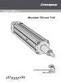
1
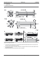
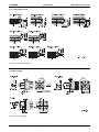
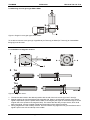
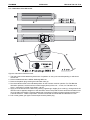
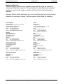
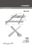
Movotrak T90 and T130
Installation and Service Manual
Edition: 4
DW110353gb-0716
THOMSON
APRIL 2007
Movotrak T90 and T130
Version History
Edition Number
1
2
3
4
Edition Date
2004
2005-02-10
2006-05-19
2007-04-17
Reason for Revision
Manual created
Updated with new T90 versions
Figure numbering corrected
Lubrication instructions updated
DANAHER MOTION is a registered trademark of Danaher Corporation. Danaher Motion makes every
attempt to ensure accuracy and reliability of the specifications in this publication. Specifications are subject
to change without notice. Danaher Motion provides this information "AS IS" and disclaims all warranties,
express or implied, including, but not limited to, implied warranties of merchantability and fitness for a
particular purpose. It is the responsibility of the product user to determine the suitability of this product for a
specific application.
©2004 Danaher - Printed in Sweden. All rights reserved.
2
DW110353gb-0716 Edition: 4
Installation and Service Manual
Movotrak T90 and T130
APRIL 2007
THOMSON
Table of Contents
1. Type designation system......................................................................................4
2. Mounting instructions...........................................................................................5
2.1
Installation................................................................................................................................. 5
2.2
Connection of load.................................................................................................................... 6
2.3
Motor flange.............................................................................................................................. 6
2.4
Feet mounting kit ...................................................................................................................... 7
2.5
Trunnion mounting kit ............................................................................................................... 7
2.6
Mounting of worm gear type BS40 / BS50 ............................................................................... 8
2.7
Installation of magnetic sensors ............................................................................................... 8
3. Service and maintenance .....................................................................................9
3.1
General maintenance instructions ............................................................................................ 9
3.2
Lubrication .............................................................................................................................. 10
4. Technical data .....................................................................................................11
4.1
Technical data ........................................................................................................................ 11
Installation and Service Manual
DW110353gb-0716 Edition: 4
3
THOMSON
APRIL 2007
Movotrak T90 and T130
1. Type designation system
T
Designation example:
09
–
B
4010
M
S
052
Unit type
T
Movotrak precision actuator
Size
90
09
130
13
Hyphen
–
Drive type
B
Ball screw and ball nut
Screw diameter / lead / tolerance
25 mm / 05 mm / T7
2505
25 mm / 10 mm / T7
2510
25 mm / 25 mm / T7
2525
32 mm / 20 mm / T7
3230
32 mm / 32 mm / T7
3232
40 mm / 10 mm / T7
4010
40 mm / 20 mm / T7
4020
40 mm / 40 mm / T7
4040
Engineering unit
M
Metric
Adapter type
N
M16 × 1,5 outside thread
M16 × 2 inside thread
P
M20 × 1,5 outside thread
Q
M20 × 1,5 inside thread
R
M27 × 2 outside thread
S
M27 × 2 inside thread
T
M33 × 2 outside thread
U
M33 × 2 inside thread
V
M30 × 2 inside thread
X
Ordering length L [cm]
•••
Table 1: Type designation system for Movotrak
Figure 1: definition of ordering length L
4
DW110353gb-0716 Edition: 4
Installation and Service Manual
Movotrak T90 and T130
APRIL 2007
THOMSON
2. Installation
2.1 Mounting instructions
Figure 2: mounting instructions
1. The actuators are equipped with T-slots along the profile and threaded side holes in the front and rear
housings, which can be used for mounting.
2. Only mount the actuator to one side if not trunnion mounting is used. Do not mount the actuator so that
the profile is deformed.
3. Mount the actuator so that the lubrication hole is accessible.
Installation and Service Manual
DW110353gb-0716 Edition: 4
5
THOMSON
APRIL 2007
Movotrak T90 and T130
2.2 Connection of load
Figure 3: connection of load
2.3 Motor flange
Figure 4: motor flanges
6
DW110353gb-0716 Edition: 4
Installation and Service Manual
Movotrak T90 and T130
APRIL 2007
THOMSON
2.4 Feet mounting kit
Figure 5: mounting feet
A
B
C
D
E
F
L
Tightening torque [Nm]
T09-B25
125
155
15
20
40
155
Smax + 141
78
T09-B32
125
155
15
20
40
155
Smax + 162
78
T13-B40
176
220
22
30
60
220
Smax + 216
220
Table 2: mounting feet dimensions
2.5 Trunnion mounting kit
Figure 6: trunnion
A
B
C
D
E
F
G
H
Tightening torque [Nm]
T09-B
150
240
130
80
ø20 f8
45
25
75
11
T13-B
316
210
180
110
Ø35 f8
63
30
93
45
Table 3: trunnion dimensions
Make sure to mount the bearings on the trunnion shafts as close to the unit as possible.
Installation and Service Manual
DW110353gb-0716 Edition: 4
7
THOMSON
APRIL 2007
Movotrak T90 and T130
2.6 Mounting of worm gear type BS40 / BS50
Figure 7: flange for worm gear type BS40 / BS50
To be able to mount a worm gear (a) of type BS40 (for T90 only) or BS50 (for T130 only) an intermediate
flange (b) must be used.
2.7 Installation of magnetic sensors
Figure 8: magnetic sensor
1. The sensors are locked in the desired position with the aid of the lock screws (a) in the T-slots (b).
2. Magnet positions at fully retracted and fully extended rod. Keep in mind that the duration of the sensor
signal is dependent upon the speed and the width of the magnet (the signal is somewhat longer than the
magnet due to the spread of the magnetic field). This means that the relay or input device, which shall
detect the signal, must be capable of detecting the duration of the signal in question.
3. Strong magnets are used of safety reasons. This will create a long signal but can give the effect that the
signal is split in two with an interrupt in the middle.
8
DW110353gb-0716 Edition: 4
Installation and Service Manual
Movotrak T90 and T130
APRIL 2007
THOMSON
3. Service and maintenance
3.1 General maintenance instructions
• The customer can perform the service and maintenance described in this manual. Other service ought to
be performed by authorised personnel / service workshop.
• Follow the recommended service intervals. Replace defective parts immediately. Only use parts of the
same make and type as original. Ordering data can be found in the spare part lists supplied with the unit.
Also state the manufacturing number of the unit (embossed in the drive end).
• T90 and T130 is not self-braking. This means that the load and the extension tube can move if the driving
force is disconnected, or if the motor, gears or brakes are detached during service. This is even more
important for vertical applications. Ensure therefore that the load is secured before service is begun.
• Check the unit in connection to lubrication. Be attentive towards the wear and function of the rod seal,
the magnetic sensors, limit switches and the mounting of them. Check all connections to the support and
the rod. Also be attentive towards a changed level of noise. Replace, repair or adjust.
• Keep the actuator clean. Wipe it off as required, particularly the rod. If cleaning fluid is required, use
small amounts and see to it that none gets into the actuator. Do not use strong cleaning agents. Dry it
fully.
• Never mix different types of oils / lubricants!
Installation and Service Manual
DW110353gb-0716 Edition: 4
9
THOMSON
APRIL 2007
Movotrak T90 and T130
3.2 Lubrication of the ball screw
Figure 9: lubrication of the ball screw
1. The ball screw is lubricated every 600 hours of operation or every 6:th month depending on whichever
comes first.
2. Recommended lubricant is Klüber Staburags NBU 30.
3. Remove the plastic plug covering the lubrication hole (a).
4. Run the extension tube to the indicated position for the actuator model in question. For T09-B25 the
lubrication position is at the maximum stroke length (Smax) of the unit – 74 mm, for T09-B32 it is at
Smax – 36 and for T13-B40 it is at Smax – 50 mm.
5. Apply 20 ml of lubricant to the ball nut by sticking a grease gun nipple (b) or a tube (c), through which the
lubricant can be applied, straight in to the lubrication hole in the profile so that it enter the lubrication hole
(d) of the ball nut assembly. Recommended type of grease gun nipple is Pressol pointed coupler M10 ×
1 female article no: 12003 or equivalent. If a tube is used the recommended tube diameter is 6 mm.
6. Pull out the grease gun nipple / tube and put back the plastic plug.
10
DW110353gb-0716 Edition: 4
Installation and Service Manual
Movotrak T90 and T130
APRIL 2007
THOMSON
4. Technical data
4.1 Technical data
T90
T09-B2505M • • • •
Max. speed
T09-B2510M • • • •
T09-B2525M • • • •
[m/s]
0,3
0,8
1,5
Max. radial load
Fr [N]
300
300
300
Max. axial load
Fx [N]
static
15 000
15 000
15 000
dynamic
10 000
10 000
10 000
Repeatability
[mm]
± 0,05
± 0,05
± 0,05
Max. input speed
[rpm]
4000
4800
4800
[kg]
5 + (L × 16,2)
5 + (L × 16,2)
5 + (LA × 16,2)
[°C]
-20 – +70
-20 – +70
-20 – +70
[mm]
5
10
25
T09-B3220M • • • •
T09-B3232M • • • •
[m/s]
1,25
2
Max. radial load
Fr [N]
500
500
Max. axial load
Fx [N]
static
25 000
25 000
dynamic
20 000
20 000
Weight
Ambient temperature
Linear move / shaft turn
Max. speed
A
A
Repeatability
[mm]
± 0,05
± 0,05
Max. input speed
[rpm]
3750
3750
Weight
[kg]
6,5 + (L × 18)
6,5 + (LA × 18)
Ambient temperature
[°C]
-20 – +70
-20 – +70
[mm]
20
32
Linear move / shaft turn
A
A
L in metres, see figure 1 for definition of L
Table 2: technical data for T90
T130
T13-B4010M • • • •
T13-B4020M • • • •
T13-B4040M • • • •
[m/s]
0,4
1
2
Max. radial load
Fr [N]
800
800
800
Max. axial load
Fx [N]
static
45 000
45 000
45 000
dynamic
40 000
35 000
15 000
Max. speed
Repeatability
[mm]
± 0,05
± 0,05
± 0,05
Max. input speed
[rpm]
2500
3000
3000
[kg]
18,5 +
18,5 +
18,5 +
Weight
A
Ambient temperature
Linear move / shaft turn
A
A
(30 × (L – 0,239))
(30 × (L – 0,239))
(30 × (LA – 0,239))
[°C]
-20 – +70
-20 – +70
-20 – +70
[mm]
10
20
40
L in metres, see figure 1 for definition of L
Table 3: technical data for T130
Installation and Service Manual
DW110353gb-0716 Edition: 4
11
Movotrak T90 and T130
APRIL 2007
THOMSON
Sales and Service
Danaher Motion products are available world wide through an extensive
authorised Distributor network. These distributors offer literature, technical
assistance and a wide range of models off the shelf for fastest possible
delivery.
Danaher Motion sales engineers are conveniently located to provide prompt
attention to customers' needs. Call the nearest office listed for ordering.
United Kingdom
Danaher Motion
Chartmoor Road, Chartwell Business Park
Leighton Buzzard, Bedfordshire
LU7 4WG; United Kingdom
Phone: +44 (0)1525 243 243
Fax:
+44 (0)1525 243 244
E-mail: [email protected]
France
Danaher Motion
C.P 80018
12, Rue Antoine Becquerel – Z.I. Sud
F-72026 Le Mans Cedex 2
France
Phone: +33 (0) 243 50 03 30
Fax:
+33 (0) 243 50 03 39
E-mail: [email protected]
Germany
Danaher Motion GmbH
Sales Office North
Wacholderstr. 40-42
40489 Düsseldorf
Germany
Phone: +49 (0) 203 9979 214
Fax:
+49 (0) 203 9979 3214
E-Mail: [email protected]
Italy
Danaher Motion srl
Largo Brughetti
I-20030 Bovisio Masciago
Italy
Phone: +39 0362 594260
Fax:
+39 0362 594263
E-mail: [email protected]
Danaher Motion GmbH
Sales Office South West
Brückenfeldstraße 26/1
75015 Bretten
Germany
Phone: +49 (0) 7252 97390 56
Fax:
+49 (0) 7252 97390 55
E-Mail: [email protected]
Sweden
Danaher Motion
Box 9053
SE-291 09 Kristianstad
Sweden
Phone: +46 (0) 44-24 67 00
Fax:
+46 (0) 44-24 40 85
E-mail: [email protected]
Danaher Motion GmbH
Sales Office South East
Kiesgräble 7
89129 Langenau
Germany
Phone: +49 (0) 7471 62 23 23
Fax:
+49 (0) 7471 62 23 26
E-Mail: [email protected]
Switzerland
Danaher Motion SA
La Pierreire 2
1029 Villars-Ste-Croix
Switzerland
Phone: +41 (0) 21 631 33 33
Fax:
+41 (0) 21 636 05 09
E-mail: [email protected]
12
DW110353gb-0716 Edition: 4
Installation Manual