1
MY100-10/14
Service Manual
TPSys™ 2.9
Original Instructions
English
P-050-0101
MYDATA
MY100-10/14
Preface
MY100-10/14
Component Placement Machines
Service Manual
Original Instructions
English
P-050-0101-EN – Service Manual
Rev. 0001 2011-09
i
Preface
MYDATA
MY100-10/14
This document is intended for the MY100-10/14 running the TPSys software version 2.9.
A standard system and available options are covered by this document. Depending on your system configuration you may lack some
of the features mentioned in the document.
Disclaimer
Hardware and software mentioned in this document are subjected to continuous development and improvement. Consequently,
there may be minor discrepancies between the information in the document and the performance or design of the product.
Specifications, dimensions and other statements mentioned in this document are subject to changes without prior notice.
Federal Communications Commission (FCC)
This equipment has been tested and found to comply with the limits for a Class A digital device, pursuant to part 15 of the FCC
Rules. These limits are designed to provide reasonable protection against harmful interference when the equipment is operated in a
commercial environment. This equipment generates, uses, and can radiate radio frequency energy and, if not installed and used in
accordance with the instruction manual, may cause harmful interference to radio communications. Operation of this equipment in
a residential area is likely to cause harmful interference in which case the user will be required to correct the interference at his own
expense.
Do not start, operate or service the
machine until you have read and
understood the safety chapter.
MYDATA and its suppliers shall not be liable for any damages related to this software or hardware, or for any other damages whatsoever caused by the use of or inability
to use any MYDATA product. This is applicable even if MYDATA has been advised of the damage risk. Under any circumstances, MYDATA’s entire liability shall be
limited to replace such defective software or hardware that was originally purchased from MYDATA.
MYDATA automation, MYDATA, MY; MY100DX, MY500, MY19, MY15, MY12, MY9 and MYSynergy; T3, T4, T5 and T6; HYDR A Speedmount, Midas, ISIC;
Agilis, Agilis Linear Magazine (ALM), Agilis Stick Magazine (ASM), MYDATA Tray Exchanger (TEX), MYDATA Tape Magazine (TM), MYDATA Tray Wagon
Magazine (TWM), MYDATA Vibratory Magazine (VM); MYDATA Standard Vision System (SVS), MYDATA Dual Vision System (DVS), MYDATA Linescan
Vision System (LVS), MYDATA HYDR A Vision System (HVS); MYDATA Assembly Process Management (APM) including; FlowLine, JPSys, TPSys, MYLabel,
MYCam, MYPlan, MYTrace, CAD Conversion, Equinox and MYLink are registered trademarks or trademarks of Micronic Mydata AB. Other trademarks mentioned
in this document are trademarks or registered trademarks of their respective owners.
Micronic Mydata AB, PO Box 3141, SE-183 03 Täby, Sweden.
Phone +46 8 638 52 00 – Fax +46 8 638 52 90 – Internet www.mydata.com
This document or parts of it may not be reproduced without a written permission of Micronic Mydata AB.
Infringements will be prosecuted. All rights reserved.
Copyright © Micronic Mydata AB, Sweden, 1990–2011.
ii
Rev. 0001 2011-09
P-050-0101-EN – Service Manual
MYDATA
MY100-10/14
Preface
Table of Contents
Text Conventions .......................................................................................................
Danger, Warning, Caution, and Note .............................................................
Italic Font .......................................................................................................
Bold Font .......................................................................................................
Menu Selections .............................................................................................
Lists ................................................................................................................
xiii
xiii
xiv
xiv
xiv
xiv
1. Safety ......................................................................................................................
Emergency Stop Button ....................................................................................
Emergency Movement of Machine Elements ...................................................
Warning Signs ...................................................................................................
Magnetic Fields ...........................................................................................
Fast Moving Machinery ...............................................................................
Dangerous Voltage ......................................................................................
Fast Horizontal Movements .........................................................................
Sharp Edges .................................................................................................
Moving the Machine ....................................................................................
Type Plate .........................................................................................................
TEX Tray Exchanger ........................................................................................
TEX Tray Exchanger Emergency Stop .......................................................
TEX Tray Exchanger Warning Signs ..........................................................
Glue Station ......................................................................................................
Warnings in the Manual ....................................................................................
Noise .................................................................................................................
Material Safety Data Sheets ..............................................................................
Oil ................................................................................................................
Grease ..........................................................................................................
Lead Acid Batteries .....................................................................................
In Case of Fire ...................................................................................................
ESD ...................................................................................................................
How To Help Prevent ESD ..........................................................................
1-1
1-2
1-3
1-4
1-4
1-6
1-8
1-10
1-11
1-12
1-13
1-14
1-14
1-15
1-16
1-16
1-17
1-17
1-17
1-17
1-18
1-19
1-19
1-19
2. Installation .................................................................................................................
2-1
Site Preparation ..............................................................................................................
Required Working Area .....................................................................................
General Site Requirements ...........................................................................
Machine Weight ............................................................................................
Shipping Gross Weight .................................................................................
Center of Gravity ..........................................................................................
Machine Dimensions ....................................................................................
Floor Space Requirement .............................................................................
Environmental Requirements .......................................................................
Electrical Requirements ................................................................................
Disposal Requirements .................................................................................
2-2
2-3
2-3
2-3
2-3
2-4
2-5
2-6
2-7
2-8
2-8
Installing the Placement Machine ..................................................................................
Requirements ................................................................................................
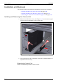
Unloading the Machine from the Truck .............................................................
Unpacking ..........................................................................................................
Moving and Placing the Machine ......................................................................
Placing the Machine .....................................................................................
Leveling the Machine ...................................................................................
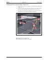
Lifting the Machine Using a Fork Lift .........................................................
Lifting the Machine Using a Crane ..............................................................
Lifting the Y Module ....................................................................................
2-9
2-9
2-10
2-11
2-12
2-13
2-14
2-15
2-18
2-20
P-050-0101-EN – Service Manual
Rev. 0001 2011-09
iii
Preface
MY100-10/14
MYDATA
Relocating the Machine ......................................................................................
Requirements .................................................................................................
Loading the Machine on a Truck .......................................................................
Powering .............................................................................................................
XNET2 Plugs ................................................................................................
Electrical Configuration ................................................................................
Electrical Connection ....................................................................................
Power Plug Connection .................................................................................
Power Cord Connection ................................................................................
Network Connection (optional) .....................................................................
Machine Installation and Calibration .................................................................
2-21
2-21
2-24
2-25
2-26
2-27
2-30
2-30
2-31
2-32
2-32
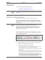
Installing External Conveyors ........................................................................................
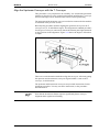
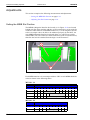
Set Preliminary Fetch-and-Leave Pos. for T Conveyor ................................
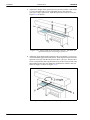
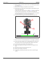
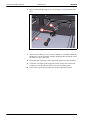
Connect the External Conveyors to the Machine ..........................................
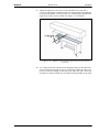
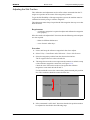
Align the Upstream Conveyor with the T Conveyor ....................................
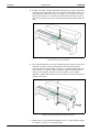
Align the Downstream Conveyor with the T Conveyor ...............................
Start Production .............................................................................................
SMEMA Standard Interface ...............................................................................
Interface Standard 1.2, Mechanical ...............................................................
Interface Standard 1.2, Electrical ..................................................................
2-33
2-33
2-35
2-37
2-41
2-41
2-42
2-42
2-42
3. Hardware Configuration ............................................................................................ 3-1
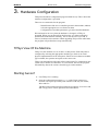
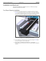
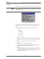
TPSys View Of the Machine ..............................................................................
Starting hwconf ..................................................................................................
Controller Viewer Window ................................................................................
Command Keys .............................................................................................
Controllers .....................................................................................................
Data ...............................................................................................................
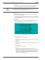
Subsystem Viewer Window ...............................................................................
Command Keys .............................................................................................
Subsystems ....................................................................................................
Data ...............................................................................................................
Configuration Settings ..................................................................................
3-1
3-1
3-2
3-2
3-2
3-2
3-3
3-3
3-4
3-4
3-5
4. Installation and Calibration ....................................................................................... 4-1
iv
Installation ......................................................................................................................
Installing the TPSys Software .......................................................................
Postinstall Program .......................................................................................
Hardware Configuration Program .................................................................
Autoinstall Procedure ....................................................................................
Machine Calibration ......................................................................................
4-2
4-2
4-2
4-2
4-3
4-3
Calibration ......................................................................................................................
Backup and Restore .......................................................................................
Requirements .................................................................................................
Starting the Calibration .................................................................................
Calibrate the vacuum system ..............................................................................
X-beam reference shape calibration ...................................................................
X-wagon camera calibration (1 or 2) .................................................................
Coarse measurement of Z-unit offset (1 or 2) ....................................................
Place area calibration ..........................................................................................
X-wagon camera 2 offset calibration .................................................................
Measure Z2 length ..............................................................................................
Z-unit offset (1 or 2) ...........................................................................................
Mount tool offset calibration (1 or 2) .................................................................
Centering Base Level measurement (1 or 2) ......................................................
Mechanical centering unit alignment (1 or 2) ....................................................
4-4
4-4
4-4
4-5
4-8
4-8
4-9
4-13
4-14
4-15
4-16
4-17
4-18
4-19
4-20
Rev. 0001 2011-09
P-050-0101-EN – Service Manual
MYDATA
MY100-10/14
Preface
Cable resistance measurement (1 or 2) ..............................................................
Optical Centering Illumination (SVC, HRC),(1 or 2) ........................................
Optical Centering Calibration (SVC, HRC),(1 or 2) .........................................
Z-Unit or Z-Unit 2 Theta Calibration ................................................................
Linescan Camera Calibration (1 or 2) ...............................................................
Optical Centering Camera Offsets (SVC, HRC, LSC), (1 or 2) .......................
Linescan Camera Fine Tune (1 or 2) .................................................................
Align HYDRA camera X/Y ...............................................................................
Coarse adjust HYDRA tool offsets (1 or 2) .......................................................
Measure HYDRA tool lengths (1 or 2) ..............................................................
Align HYDRA reference background (1 or 2) .................................................
Measure HYDRA camera Z level ......................................................................
Calibrate HYDRA camera optics (coarse), (1 or 2) ...........................................
Measure HYDRA reference background height (1 or 2) ..................................
Calibrate HYDRA camera optics (fine), (1 or 2) ...............................................
Measure HYDRA reference line (1 or 2) ...........................................................
Measure HYDRA tool offsets (1 or 2) ...............................................................
Measure centering offsets for HYDRA camera .................................................
Measure centering offsets for Linescan camera (1 or 2) ....................................
4-21
4-22
4-25
4-28
4-29
4-31
4-32
4-33
4-34
4-35
4-36
4-37
4-38
4-40
4-41
4-43
4-44
4-45
4-46
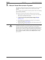
5. Mount Head Movement System ...............................................................................
5-1
5-2
5-2
5-7
5-10
5-10
5-10
5-11
5-12
5-12
5-12
5-13
5-13
5-15
5-18
5-20
5-21
5-23
5-25
5-27
5-29
5-33
5-37
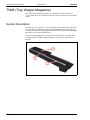
System Description ............................................................................................
X-Wagon Parts ..............................................................................................
X-Beam Parts ................................................................................................
Electrical System ...............................................................................................
Schematics ....................................................................................................
Electrical Parts ..............................................................................................
CSEL (City Select) .......................................................................................
Power supply ................................................................................................
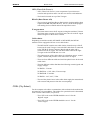
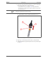
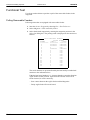
Functional Test ...................................................................................................
Show Transducer Positions ...........................................................................
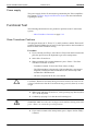
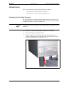
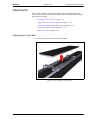
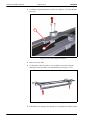
Adjustments .......................................................................................................
Adjusting the End Stop Bumpers .................................................................
Adjusting the X-wagon Readhead ................................................................
Adjusting the ATA Sensors ..........................................................................
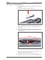
Installation and Removal ...................................................................................
Removing and Installing the Mount Head Carrier Plate ..............................
Removing and Installing the Heat Sink Unit ................................................
Removing and Installing the Magnetic Strips ..............................................
Removing and Installing the Linear Guide Blocks .......................................
Removing and Installing the Guiding Rails ..................................................
Removing and Installing the X-beam Steel Strip .........................................
Removing and Installing the Cable Chain ....................................................
6. Mount Heads .............................................................................................................
6-1
Midas ..............................................................................................................................
System Description ............................................................................................
Theta movement ...........................................................................................
Z movement ..................................................................................................
Electrical System ...............................................................................................
Schematics ....................................................................................................
Electric Parts .................................................................................................
CSEL (City Select) .......................................................................................
Power Supply ................................................................................................
Functional Test ...................................................................................................
Adjustments .......................................................................................................
Measuring Midas Cog Play ..........................................................................
6-2
6-3
6-3
6-3
6-4
6-4
6-4
6-4
6-4
6-5
6-5
6-5
P-050-0101-EN – Service Manual
Rev. 0001 2011-09
v
Preface
MY100-10/14
MYDATA
Adjusting the Midas Cog Play ...................................................................... 6-6
Troubleshooting .................................................................................................. 6-7
Repair Guidelines ............................................................................................... 6-7
Midas II ...........................................................................................................................
System Description .............................................................................................
Theta movement ............................................................................................
Z movement ...................................................................................................
Electrical System ................................................................................................
Schematics .....................................................................................................
Electric Parts .................................................................................................
CSEL (City Select) ........................................................................................
Power Supply ................................................................................................
Functional Test ...................................................................................................
Adjustments ........................................................................................................
Adjusting Midas II Cog Play .........................................................................
Troubleshooting ..................................................................................................
Repair Guidelines ...............................................................................................
6-8
6-9
6-9
6-9
6-10
6-10
6-10
6-10
6-10
6-11
6-11
6-12
6-13
6-13
HYDRA Mount Head .....................................................................................................
System Description .............................................................................................
Z movement ...................................................................................................
Theta movement ............................................................................................
HYDRA Latches ...........................................................................................
HZ Indicators .................................................................................................
Electrical System ................................................................................................
Schematics .....................................................................................................
Electric Parts .................................................................................................
CSEL (City Select) ........................................................................................
Functional Test ...................................................................................................
Adjustments ........................................................................................................
Adjusting the HYDRA Z indicators ..............................................................
Cog Play Adjustment ....................................................................................
Installation ..........................................................................................................
Troubleshooting ..................................................................................................
Repair Guidelines ...............................................................................................
6-14
6-15
6-17
6-18
6-19
6-20
6-21
6-21
6-21
6-21
6-22
6-22
6-22
6-24
6-25
6-32
6-32
7. Tools & Tool Banks .................................................................................................. 7-1
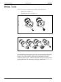
Midas Tools ....................................................................................................................
Custom Tools ................................................................................................
Installation and Removal ....................................................................................
Installing Midas Tools ...................................................................................
7-2
7-3
7-4
7-4
Midas Tool Bank ............................................................................................................
MY100DX Tool Bank ...................................................................................
MY100SX Tool Bank ...................................................................................
Installation and Removal ....................................................................................
Installing the Midas Tool Bank .....................................................................
Removing the Midas Tool Bank ...................................................................
7-5
7-5
7-7
7-8
7-8
7-8
HYDRA Mount Tools .................................................................................................... 7-9
HYDRA Tool Bank ........................................................................................................
System Description .............................................................................................
Tool Bank Parts .............................................................................................
Tool Bank Positions, Slots and Rows ...........................................................
Installation and Removal ....................................................................................
Installing HYDRA Tool Bank .......................................................................
vi
Rev. 0001 2011-09
7-10
7-10
7-11
7-12
7-13
7-13
P-050-0101-EN – Service Manual
MYDATA
MY100-10/14
Uninstalling HYDRA Tool Bank .................................................................
Adjustments .......................................................................................................
Adjust Tool Bank Angle ...............................................................................
Overlapping Tool Banks ...............................................................................
8. Mechanical Centering and Verification ....................................................................
Preface
7-14
7-15
7-15
7-15
System Description ............................................................................................
Right Centering Unit .....................................................................................
Left Centering Unit .......................................................................................
Mechanical Centering ...................................................................................
Mechanical Verification ...............................................................................
Electrical Verification ...................................................................................
Electrical System ...............................................................................................
Schematics ....................................................................................................
Functional Test ...................................................................................................
Adjustments .......................................................................................................
Repair Guidelines ...............................................................................................
Replace Centering Jaws ................................................................................
8-1
8-1
8-2
8-3
8-4
8-4
8-4
8-5
8-5
8-6
8-6
8-8
8-8
9. Vision Systems ..........................................................................................................
9-1
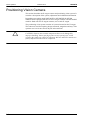
Positioning Vision Camera ............................................................................................. 9-2
X-Wagon Camera ...........................................................................................................
Electrical System ...............................................................................................
Schematics ....................................................................................................
Electric Parts .................................................................................................
Power supply ................................................................................................
Adjustments .......................................................................................................
Adjusting the X-Wagon Camera Focus ........................................................
Adjusting the X-Wagon Camera Y Position ................................................
9-3
9-4
9-4
9-4
9-4
9-5
9-5
9-7
Optical Centering Cameras ............................................................................................ 9-9
Standard and Dual Vision Camera .................................................................................
System Description ............................................................................................
Programmable Illumination ..........................................................................
Electrical System ...............................................................................................
Schematics ....................................................................................................
Electrical parts ..............................................................................................
Power supply ................................................................................................
Adjustments .......................................................................................................
Adjusting the SVC or DVC (Y position) ......................................................
9-10
9-11
9-12
9-13
9-13
9-13
9-13
9-14
9-14
HYDRA Camera 2 (HC2) ..............................................................................................
System Description ............................................................................................
HC2 Dump Bin .............................................................................................
Electrical System ...............................................................................................
Schematics ....................................................................................................
Electrical parts ..............................................................................................
Power supply ................................................................................................
Adjustments .......................................................................................................
Adjusting the HC2 (Y position) ....................................................................
9-15
9-15
9-16
9-17
9-17
9-17
9-17
9-18
9-18
Linescan Vision Camera (LVC) .....................................................................................
System Description ............................................................................................
Camera box ...................................................................................................
Electrical System ...............................................................................................
Schematics ....................................................................................................
Electrical parts ..............................................................................................
9-20
9-20
9-21
9-22
9-22
9-22
P-050-0101-EN – Service Manual
Rev. 0001 2011-09
vii
Preface
MY100-10/14
MYDATA
Power Supply ................................................................................................
Installation and Removal ....................................................................................
Installing and Removing the Camera Unit ....................................................
Installing and Removing the Power Supply Unit ..........................................
Connecting the Camera Unit and Power Supply Unit ...................................
Troubleshooting ..................................................................................................
9-23
9-24
9-24
9-25
9-26
9-27
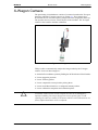
10. Pneumatic System ................................................................................................ 10-1
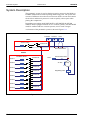
System Description ...........................................................................................
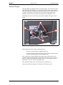
Vacuum Pumps ...........................................................................................
Vacuum and Pressure Hose Routing ...........................................................
Vacuum and Pressure Sensors .....................................................................
Midas Mounthead (Single Nozzle) .............................................................
HYDRA Mounthead (Multiple Nozzles) ....................................................
Functional Test .................................................................................................
Measure and Control Vacuum System ........................................................
Vacuum Diagnostics for MY100 ................................................................
Automatic Diagnostic Test ..........................................................................
Extensive Diagnostic Test ...........................................................................
Adjustments ......................................................................................................
Adjusting the Vacuum Pump Pressure ........................................................
10-2
10-3
10-4
10-5
10-6
10-7
10-8
10-8
10-9
10-9
10-12
10-14
10-14
11. Power Supply and Electronic System .................................................................. 11-1
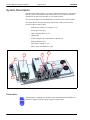
System Description ...........................................................................................
Schematics ...................................................................................................
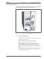
Main Power Switch .....................................................................................
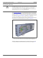
PIU (Power Inlet Unit) ................................................................................
CB3 (Computer Box 3) ...............................................................................
XBOX ..........................................................................................................
TCFS (Temperature Controlled Fan Speed) ...............................................
Battery Support ...........................................................................................
PS5 (Power Supply 5) .................................................................................
EPT3 (Auto Transformer 3) ........................................................................
Functional Test .................................................................................................
Monitoring the State of the Hard Disks ......................................................
11-2
11-2
11-3
11-4
11-5
11-7
11-9
11-10
11-11
11-12
11-13
11-13
12. Board Handling System ....................................................................................... 12-1
viii
YM (Y Module) ............................................................................................................
System description ...........................................................................................
Electrical System ..............................................................................................
Schematics ...................................................................................................
Electric parts ................................................................................................
CSEL (City Select) ......................................................................................
Power supply ...............................................................................................
Adjustments ......................................................................................................
Measure Friction On Y Module ..................................................................
12-2
12-2
12-4
12-4
12-4
12-4
12-4
12-5
12-5
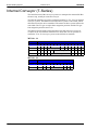
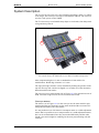
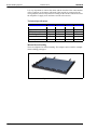
Internal Conveyor (T-Series) ........................................................................................
System Description ...........................................................................................
Electrical System ..............................................................................................
Schematics ...................................................................................................
Electric parts ................................................................................................
CSEL (City Select) ......................................................................................
12-6
12-7
12-9
12-9
12-9
12-9
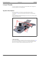
Cover Hoods .................................................................................................................
System Description ...........................................................................................
Adjustments ......................................................................................................
Measure Friction On the T-Series Board Handling System ........................
External Conveyor System ...............................................................................
12-10
12-10
12-11
12-11
12-12
Rev. 0001 2011-09
P-050-0101-EN – Service Manual
MYDATA
MY100-10/14
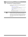
13. Component Feeding Systems
Preface
.............................................................................. 13-1
Magazine Interface .......................................................................................................
MCU (Magazine Controller Unit) ..............................................................
Magazine Mechanical Interface ..................................................................
Electrical System .............................................................................................
Schematics ..................................................................................................
Electric Parts ...............................................................................................
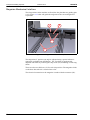
Adjustments .....................................................................................................
Setting the MIBB Slot Position ..................................................................
Adjusting the Slot Position .........................................................................
13-2
13-2
13-4
13-5
13-5
13-5
13-6
13-6
13-7
Magazines ..................................................................................................................... 13-9
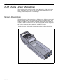
ALM (Agilis Linear Magazine) ...................................................................................
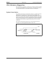
System Description ..........................................................................................
Functional Description ................................................................................
Magazine Panel ...........................................................................................
Electrical System .............................................................................................
Schematics ..................................................................................................
Electric Parts ...............................................................................................
Functional Test .................................................................................................
Polling Removable Feeders ........................................................................
Repair Guidelines .............................................................................................
13-10
13-10
13-11
13-12
13-13
13-13
13-13
13-14
13-14
13-15
AM8 (Agilis Magazine 8) ............................................................................................
System Description ..........................................................................................
Panel ...........................................................................................................
Electrical System .............................................................................................
Schematics ..................................................................................................
Electric Parts ...............................................................................................
Functional Test .................................................................................................
Polling Removable Feeders ........................................................................
Adjustments .....................................................................................................
AM8 (Agilis Magazine 8) Pick Line Adjustment .......................................
Troubleshooting ...............................................................................................
Locating Errors ...........................................................................................
Magazine Errors ..........................................................................................
LED Indicated Error ...................................................................................
Pick Error ....................................................................................................
Feed Error ...................................................................................................
Machine Errors ...........................................................................................
Repair Guidelines .............................................................................................
13-16
13-16
13-16
13-17
13-17
13-17
13-17
13-17
13-18
13-18
13-19
13-19
13-20
13-20
13-21
13-21
13-22
13-23
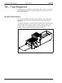
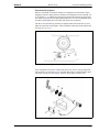
TM – Tape Magazines ..................................................................................................
System Description ..........................................................................................
TM (Tape Magazine) User Interface ...............................................................
Electrical System .............................................................................................
Schematics ..................................................................................................
Electric Parts ...............................................................................................
Functional Tests ...............................................................................................
Test Magazine .............................................................................................
Polling Magazines ......................................................................................
Adjustments .....................................................................................................
Adjusting Pick-Up Position ........................................................................
Adjusting Feeder Arm Gap .........................................................................
Setting Code Disc Synchronization ............................................................
Measuring Feeder Wheel Friction ..............................................................
13-24
13-24
13-26
13-27
13-27
13-27
13-28
13-28
13-28
13-29
13-29
13-31
13-32
13-33
P-050-0101-EN – Service Manual
Rev. 0001 2011-09
ix
Preface
MY100-10/14
MYDATA
ASM (Agilis Stick Magazine) ......................................................................................
System Description ...........................................................................................
ASP (Agilis Stick Pallet) .............................................................................
Panel ............................................................................................................
Electrical System ..............................................................................................
Schematics ...................................................................................................
Electric Parts ...............................................................................................
Repair Guidelines .............................................................................................
13-34
13-34
13-35
13-35
13-36
13-36
13-36
13-36
VM (Vibratory Magazine) ............................................................................................
System Description ...........................................................................................
Electrical System ..............................................................................................
Schematics ...................................................................................................
Electric Parts ...............................................................................................
Adjustments ......................................................................................................
Adjusting the Vibratory Unit .......................................................................
13-37
13-37
13-38
13-38
13-38
13-39
13-39
TWM (Tray Wagon Magazine) ....................................................................................
System Description ...........................................................................................
Adjustments ......................................................................................................
Adjusting the Tray Table .............................................................................
Aligning the Left Side Ball Bushings .........................................................
Adjusting the Right Side Ball Bearings ......................................................
Adjusting the Belt Tension ..........................................................................
Measure Friction .........................................................................................
Installation and Removal ..................................................................................
Tray Wagon Magazine Installation .............................................................
Tray Wagon Magazine Removal .................................................................
13-40
13-40
13-41
13-41
13-43
13-44
13-45
13-45
13-46
13-46
13-48
14. Peripheral Systems ............................................................................................... 14-1
Signal Tower .................................................................................................................
Machine States ............................................................................................
Default Settings ...........................................................................................
Functional Test .................................................................................................
Testing the Signal Tower ............................................................................
14-2
14-2
14-3
14-3
14-3
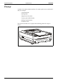
Printer ........................................................................................................................... 14-4
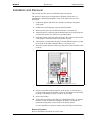
Installation and Removal .................................................................................. 14-5
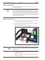
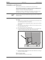
Glue Station .................................................................................................................. 14-6
System Description ........................................................................................... 14-6
Installation and Removal .................................................................................. 14-7
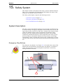
15. Safety System ....................................................................................................... 15-1
System Description ...........................................................................................
Emergency Stop Buttons .............................................................................
Cover and Hood Switches ...........................................................................
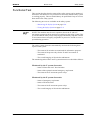
Electrical System ..............................................................................................
Schematics ...................................................................................................
Functional Test .................................................................................................
Monitoring the Safety System .....................................................................
Testing the Safety System ...........................................................................
15-1
15-1
15-2
15-2
15-2
15-3
15-4
15-4
16. Maintenance ......................................................................................................... 16-1
Maintenance Intervals ......................................................................................
Cleaning Optics ...........................................................................................
Lubricants ....................................................................................................
Spare parts ...................................................................................................
x
Rev. 0001 2011-09
16-1
16-2
16-2
16-2
P-050-0101-EN – Service Manual
MYDATA
MY100-10/14
Preface
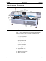
Maintenance Overview ................................................................................................
Requirements ..............................................................................................
Preparation ..................................................................................................
Calibration ..................................................................................................
16-3
16-4
16-4
16-4
Monthly or 160 Hours Maintenance ............................................................................
Clean and Lubricate Midas Tools ....................................................................
Preserve DVC (Dual Vision Camera) ..............................................................
Preserve LSC (LineScan Camera) ...................................................................
Preserve HC2 (HYDRA Camera 2) .................................................................
Clean and Lubricate Mechanical Centering Unit .............................................
Clean and Lubricate Midas Mount Head .........................................................
Clean and Lubricate Midas II Mount Head .....................................................
Clean the HYDRA Reference Background .....................................................
Clean and Lubricate HYDRA Vacuum Tubes .................................................
Clean and Lubricate HYDRA Tool Tubes .......................................................
Preserve HYDRA Mount Tools .......................................................................
Clean and Lubricate Tray Wagon Magazine ...................................................
Replace Midas Vacuum Filter .........................................................................
Preserve Linear Scales .....................................................................................
Preserve LCD Screen and Warning Signs .......................................................
16-5
16-6
16-7
16-8
16-9
16-10
16-11
16-12
16-13
16-14
16-16
16-19
16-20
16-21
16-22
16-23
Yearly or 2000 Hours Maintenance .............................................................................
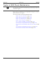
Replace Top Cover Fan Filters ........................................................................
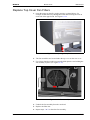
Replace Electronic Shelf Filter ........................................................................
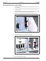
Replace Front Hood Fan Filter ........................................................................
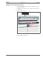
Replace Vacuum Pump Filter ..........................................................................
Preserve Midas and HYDRA Tool Bank .........................................................
Clean and Lubricate HYDRA Guide Bearings ................................................
Clean and Lubricate HYDRA Gear Rack and Latch Fingers ..........................
Clean and Lubricate HYDRA Vacuum Pipe Unit ...........................................
Clean and Lubricate Midas II Mount Head .....................................................
16-24
16-25
16-26
16-27
16-28
16-29
16-30
16-30
16-31
16-32
X Wagon 2000 km .......................................................................................................
Clean and Lubricate X-Beam Guiding Rails ...................................................
Maintenance Quick Guide Tables ....................................................................
Monthly or 160 Hours Maintenance ...........................................................
Yearly or 2000 Hours Maintenance ............................................................
X Wagon 2000 km Maintenance ................................................................
16-36
16-37
16-40
16-40
16-41
16-42
Appendix A - Service Program Reference Guide .......................................................... A-1
Main Menu Options ........................................................................................... A-2
Board ............................................................................................................. A-3
Motor ............................................................................................................ A-4
Head .............................................................................................................. A-9
Magazine ....................................................................................................... A-11
Vacuum ......................................................................................................... A-13
Conveyor ....................................................................................................... A-15
Camera .......................................................................................................... A-18
Utility ............................................................................................................ A-19
Appendix B – About the Documentation .......................................................................
Operator's Manual ..............................................................................................
Programming Manual ........................................................................................
Service Manual ..................................................................................................
Software Manual ................................................................................................
Spare Parts Catalog ............................................................................................
Supplementary Software ....................................................................................
P-050-0101-EN – Service Manual
Rev. 0001 2011-09
B-1
B-2
B-2
B-3
B-3
B-3
B-4
xi
Preface
MY100-10/14
MYDATA
MYCenter .....................................................................................................
MYPlan ........................................................................................................
MYLabel ......................................................................................................
MYTrace ......................................................................................................
FlowLine ......................................................................................................
B-4
B-4
B-4
B-5
B-5
Index ................................................................................................................................ I-1
xii
Rev. 0001 2011-09
P-050-0101-EN – Service Manual
MYDATA
MY100-10/14
Preface
Text Conventions
This document uses text conventions to present information in various
situations. This is explained below.
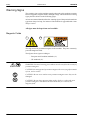
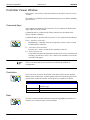
Danger, Warning, Caution, and Note
In this document a particular text layout is used to make danger, warning, and
caution information evident. A triangular icon identifies the type of risk and
the text describes the risk.
Danger, warning, and caution information must be followed.
Assisting information, notes, have the same layout but never triangular icons.
Danger
DANGER! Danger means a potentially dangerous situation that can cause
death or severe bodily injury. The icon identifies the type of risk.
Warning
WARNING! Warning means a potentially dangerous situation that can cause
bodily injury or considerable damage to the system or equipment. The icon
identifies the type of risk.
Caution
CAUTION! Caution means that the system or equipment can be damaged or
data be lost. To distinguish caution information from warning and danger
information, this icon is always an empty triangle.
Note, example 1
A note contains any type of assisting information.
Note, example 2
P-050-0101-EN – Service Manual
One type of assisting information is tips, which normally have this icon.
Rev. 0001 2011-09
xiii
Preface
MY100-10/14
MYDATA
Italic Font
Italic font is used for software screen text (for example Parameter 1), names
(for example Spare Parts Catalog), and for warning text (described in the
previous section).
Bold Font
Bold font is used for particular important words (for example, This must not
be done in reverse order).
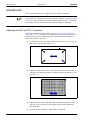
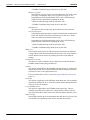
Menu Selections
When describing software handling, menu selections are described in the
following format:
File > Page Setup > Paper Size > Portrait > OK
This example describes to open the File menu and select the Page Setup,
Paper Size, and Portrait options, and finally click the OK button.
Lists
Lists of items, points to consider, or procedures that have no relative order
appear in bulleted or hyphenated format like this:
•
•
Item 1.
Item 2.
or
– Item 1.
– Item 2.
Procedures that must be performed in a specific order appear in numbered lists
like this:
1. Perform this step first.
2. Perform this step second.
xiv
Rev. 0001 2011-09
P-050-0101-EN – Service Manual
MYDATA
MY100-10/14
Safety
1. Safety
Before starting the machine, it is necessary that the operator, foreman and any
other personnel involved in machine operation, maintenance or service
understand and follow these points:
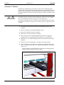
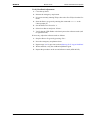
•
This machine is designed to pick components from their packaging and
place them onto printed circuit boards, and to apply glue. The machine must
be used exclusively for these two purposes and nothing else.
•
The machine must be operated by qualified personnel only. Qualified
personnel should meet the following qualifications:
– Be above 18 years of age.
– Have normal depth perception, field of vision, reaction time, manual
dexterity, coordination, and no tendency to dizziness.
– Completed operators training.
P-050-0101-EN – Service Manual
•
All personnel involved in machine operation must understand the use of the
emergency stop buttons and how to manually move machine elements in
case of emergency. See the Emergency Stop Button and Emergency
Movement of Machine Elements sections in this chapter.
•
Anyone operating this machine must obey all warning signs. See the
Warning Signs section in this chapter.
•
At least one manual that describes the warning signs of the particular
machine type must always be kept, for instance if the machine is upgraded
with a later TPSys version.
•
Apart from the daily maintenance described in the operator's manual, the
machine is to be serviced by authorized maintenance engineers only.
•
Excess component tape from tape magazines shall be cut from the front of
the machine when it is not in operation.
•
When inserting or removing tools to or from the tool bank, the emergency
stop button shall be pressed down.
•
The emergency stop button shall be pressed down when a tool or component
is manually inserted or removed from the X wagon of the machine.
•
If there is a risk that any unauthorized personnel might alter the system
settings and thus the behavior of the machine, then the logon facility for
individual access rights has to be used.
•
Ensure that all covers and shields are intact, mounted and closed while the
machine is in operation.
•
•
Do not disable or disengage any safety switch or sensor.
•
Do not use chemicals or other substances that may have any influence on
the operator or other personnel involved in the machine operation.
Do not configure or modify MYDATA machines or devices without
consulting MYDATA. The machines, devices or the interfaces between
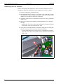
them might become unsafe.
Rev. 0001 2011-09
1-1
Safety
MYDATA
MY100-10/14
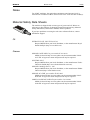
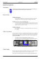
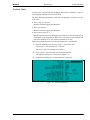
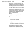
Emergency Stop Button
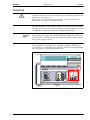
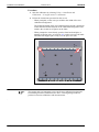
All MYDATA placement machines have red emergency stop buttons. These
will stop all machine movements immediately when pressed down.
Figure 1-1. Emergency stop button.
There is one emergency stop button located at the front of the machine, at the
keyboard. This emergency stop button is released by being turned clockwise.
WARNING! The emergency stop button must always be pressed down when
hands, fingers, tools or other objects are within a shielded area or in the risk
area of movable machine elements such as internal conveyors, Y wagon or
Tray Wagon Magazine.
Emergency stop buttons on all MYDATA optional devices, such as TEX Tray
Exchanger and conveyor systems, have the same function. They switch off all
motors, and release movable machine elements.
Activating a stop system in an optional device, for instance opening a TEX
Tray Exchanger door, stops only that optional device. The placement machine
is not stopped by such an action.
Restart
To restart a machine after an emergency stop button has been released, enter
any command on the keyboard.
1-2
Rev. 0001 2011-09
P-050-0101-EN – Service Manual
MYDATA
MY100-10/14
Safety
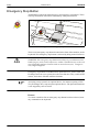
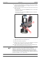
Emergency Movement of Machine Elements
The X wagon, Y wagon, and Tray Wagon can be moved manually after
pressing the emergency stop button down.
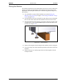
If an accident has occurred and an emergency movement of a machine element
is required, use the following procedure:
1. Press the emergency stop button down.
This will immediately stop the machine and disconnect the motors used
to position the machine elements.
2. Move the machine element away by hand.
P-050-0101-EN – Service Manual
Rev. 0001 2011-09
1-3
Safety
MY100-10/14
MYDATA
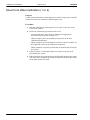
Warning Signs
The warning signs on the machine must be observed as this machine contains
fast moving parts, magnetic fields, and high voltage. The machine has warning
signs placed as shown on the following pages.
At least one manual that describes the warning signs of the particular machine
type must always be kept, for instance if the machine is upgraded with a later
TPSys version.
All signs must be kept clean and readable.
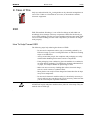
Magnetic Fields
1
2
This sign warns for permanent magnets in the machine. They have extremely
powerful magnetic fields.
The figures show signs according to:
– European and Canadian standards ('1').
– US standards ('2').
1-4
WARNING! Personnel wearing pace-makers must be careful in the vicinity of
permanent magnets.
CAUTION! Do not approach permanent magnets when carrying objects made
of iron, steel or nickel.
CAUTION! Do not wear watches near permanent magnets since they can be
damaged.
CAUTION! Do not bring magnetic data media, check or credit cards near
permanent magnets. The data on the data media may be erased by the
magnetic field.
Rev. 0001 2011-09
P-050-0101-EN – Service Manual
MYDATA
MY100-10/14
Safety
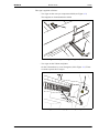
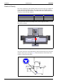
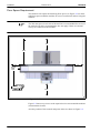
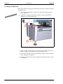
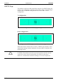
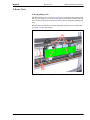
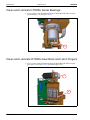
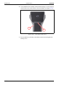
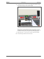
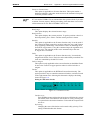
This sign is applied as follows.
– Two signs on the conveyor component shield (see Figure 1-2).
The magnets are located under the shield.
Figure 1-2. Signs warning for magnetic fields.
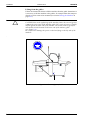
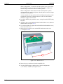
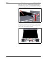
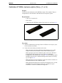
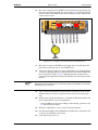
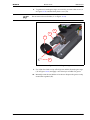
– Two signs on the X beam end plates.
On the X beam there is a row of magnets ('M' in Figure 1-3). These
are used to power the X wagon.
M
Figure 1-3. Warning sign on the right end plate.
P-050-0101-EN – Service Manual
Rev. 0001 2011-09
1-5
Safety
MYDATA
MY100-10/14
Fast Moving Machinery
1
2
This sign warns of fast machine movements. Ensure that all covers and shields
are intact, mounted and closed while the machine is in operation. Do not
disable or disengage any safety switch or sensor.
The figures show signs according to:
– European and Canadian standards ('1').
– US standards ('2').
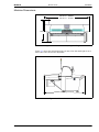
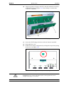
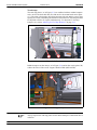
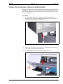
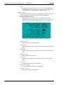
This sign is applied as follows.
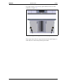
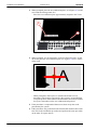
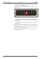
– Two signs on the front glass shield, see Figure 1-4.
These signs warn of the fast X-wagon movement.
Figure 1-4. Warning signs and striped tape on the front glass.
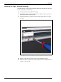
A striped warning tape on the bottom of the glass shield indicates the
dangerous area. No hands, fingers, or other objects are allowed beyond the
glass shield.
1-6
Rev. 0001 2011-09
P-050-0101-EN – Service Manual
MYDATA
MY100-10/14
Safety
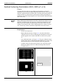
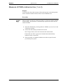
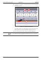
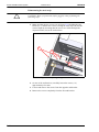
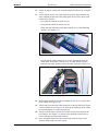
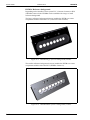
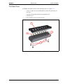
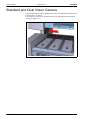
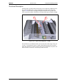
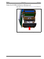
– Two signs on the T3-T6 conveyor glass shield (on the rear of the
machine), see Figure 1-5.
Figure 1-5. Signs on rear conveyor glass.
These signs warn of fast Y-wagon movements. No hands, fingers, or
other objects are allowed beyond the glass shields.
P-050-0101-EN – Service Manual
Rev. 0001 2011-09
1-7
Safety
MYDATA
MY100-10/14
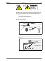
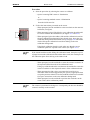
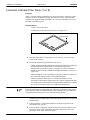
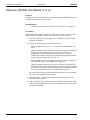
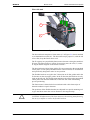
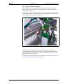
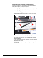
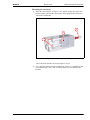
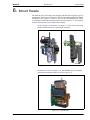
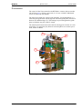
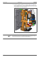
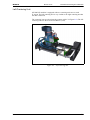
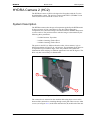
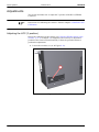
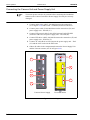
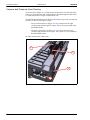
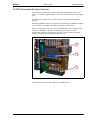
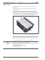
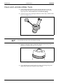
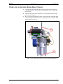
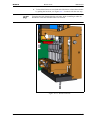
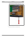
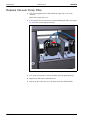
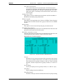
Dangerous Voltage
This sign warns of dangerous residual voltage in an internal electronic cabinet
(see Figure 1-6). This cabinet has powerful capacitors. When power is cut,
these capacitors are still charged with live voltage. Only authorized service
personnel are allowed to open the machine when such a unit is open.
Figure 1-6. Electronic cabinet.
Disconnect input power before servicing the machine. Wait at least five
minutes before opening the cabinet to allow residual voltage to be discharged.
1-8
DANGER! Always lock out and tag the main switch before opening the hoods
and commencing any servicing within the machine.
Rev. 0001 2011-09
P-050-0101-EN – Service Manual
MYDATA
MY100-10/14
1
Safety
2
HAZARDOUS
VOLTAGE.
Disconnect power
before servicing.
This sign warns of electric shock. Units, on which this sign is placed, contain
dangerous voltage levels. Power must be switched off before opening the unit.
Only authorized service personnel are allowed to operate the machine when
such a unit is open. Hazardous voltage is present with machine power off.
The figures show signs according to:
– European and Canadian standards ('1').
– US standards ('2').
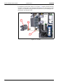
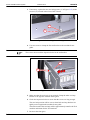
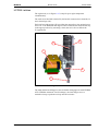
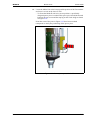
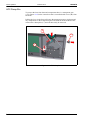
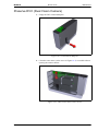
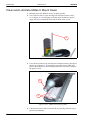
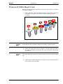
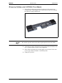
This sign is applied as follows.
– One sign at the main switch, see Figure 1-7.
Figure 1-7. Sign at the main switch.
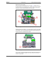
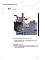
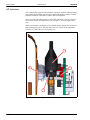
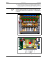
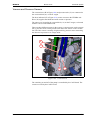
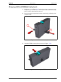
– One sign on the Power Input Unit (PIU) cover, inside the machine, see
Figure 1-8.
Figure 1-8. Sign on the PIU, inside the machine.
P-050-0101-EN – Service Manual
Rev. 0001 2011-09
1-9
Safety
MYDATA
MY100-10/14
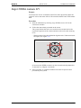
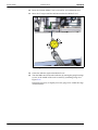
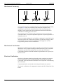
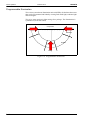
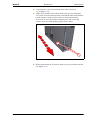
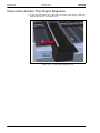
Fast Horizontal Movements
1
2
This sign warns of fast horizontal movements. The sign is located on optional
Tray Wagon Magazines (TWM) and it is applied as follows.
– Two signs on the TWM (see Figure 1-9).
The figures show signs according to:
– European and Canadian standards ('1').
– US standards ('2').
Figure 1-9. Signs on the TWM.
1-10
Rev. 0001 2011-09
P-050-0101-EN – Service Manual
MYDATA
MY100-10/14
Safety
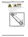
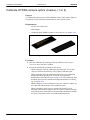
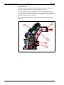
Sharp Edges
1
2
This sign warns of sharp edges on the steel strip. The sign is located on top of
the X beam under the top cover. The sign is applied as follows.
– Two signs on top of the X beam. One sign in each end of the X beam
(see Figure 1-10).
The figures show signs according to:
– European and Canadian standards ('1').
– US standards ('2').
Figure 1-10. Signs on the X beam.
P-050-0101-EN – Service Manual
Rev. 0001 2011-09
1-11
Safety
MY100-10/14
MYDATA
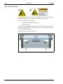
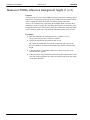
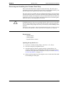
Moving the Machine
1
2
This sign warns of a tip over risk. There is always a tip over risk when moving
the machine, especially if you push it in the backward direction.
The figures show signs according to:
– European and Canadian standards ('1').
– US standards ('2').
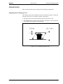
The machine is equipped with 2 signs at delivery. The warning signs should
be removed after installation. If the machine has to be moved the warning
signs must be applied again.
Apply the signs as shown in Figure 1-11.
Figure 1-11. Warning signs to use when moving the machine.
1-12
Rev. 0001 2011-09
P-050-0101-EN – Service Manual
MYDATA
MY100-10/14
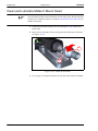
Safety
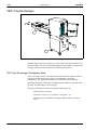
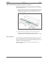
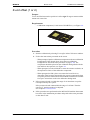
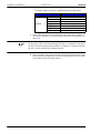
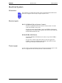
Type Plate
A type plate shows the name and address of the manufacturer, the machine
type and serial number, and manufacturing year and country. An example of a
type plate is shown below.
Figure 1-12. Machine type plate.
The type plate is found at the back of the machine, on the machine stand.
P-050-0101-EN – Service Manual
Rev. 0001 2011-09
1-13
Safety
MYDATA
MY100-10/14
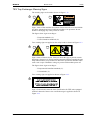
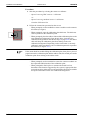
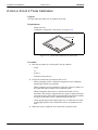
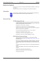
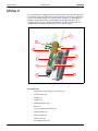
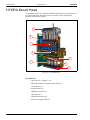
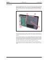
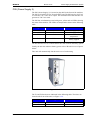
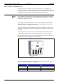
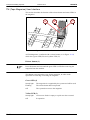
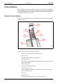
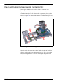
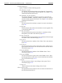
TEX Tray Exchanger
1
3
2
2
Figure 1-13. TEX Tray Exchanger.
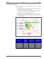
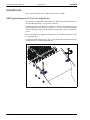
Number and position of each sign type is described in the following text. If a
sign is missing, it must be replaced immediately. Part numbers are printed on
the signs, but can also be read from the following description.
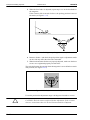
TEX Tray Exchanger Emergency Stop
There are safety switches at the two hoods and at the door. When a switch is
activated, all movements in the TEX Tray Exchanger are stopped
immediately. The placement machine is not affected by these switches.
When the emergency stop button on the placement machine is pressed down,
the TEX Tray Exchanger is also stopped.
TEX Tray Exchanger can thus be stopped in following ways:
– The front door is opened.
– The front or rear cover is opened ('1' in Figure 1-13).
– The emergency stop button on the placement machine is pressed
down.
1-14
Rev. 0001 2011-09
P-050-0101-EN – Service Manual
MYDATA
MY100-10/14
Safety
TEX Tray Exchanger Warning Signs
The warning signs are located as shown in Figure 1-13.
1
1
2
Sign 1 warns of fast machine movements. Ensure that all covers and shields
are intact, mounted and closed while the machine is in operation. Do not
disable or disengage any safety switch or sensor.
The figures show signs according to:
– European standards ('1').
– US and Canadian standards ('2').
Two warning signs are applied on the safety hoods as shown in Figure 1-13.
2
1
2
Sign 2 warns of electric shock. Units, on which this sign is placed, contain
dangerous voltage levels. Power must be switched off before opening the unit.
Only authorized service personnel are allowed to operate the machine when
such a unit is open. Hazardous voltage is present with machine power off.
The figures show signs according to:
– European and Canadian standards ('1').
– US standards ('2').
Two warning signs are applied as shown in Figure 1-13.
3
Sign 3 (D-024-0345) states the laser classification for TEX units equipped
with laser barcode scanner. One certification sign is applied as shown in
Figure 1-13.
P-050-0101-EN – Service Manual
Rev. 0001 2011-09
1-15
Safety
MYDATA
MY100-10/14
Glue Station
The glue station has a safety shield. This will ensure that no fingers or hands
can pass beyond the machines glass shield.
Ensure that this cover is intact and mounted while the machine is in operation.
Figure 1-14. Glue station safety shields.
Warnings in the Manual
Throughout the manual this symbol is used to call your attention to commands
that starts machine movements. The symbol refers to the warning signs, which
must be obeyed to eliminate the risk of injury. If there are instructions
accompanying this symbol, they must be followed.
Also, to avoid damage, this symbol means that the operator must be observant
of the following:
Ensure that there are no foreign objects on the assembly table, near the tool
bank, or within the X wagon, Y wagon, or Tray Wagon Magazine moving
areas, and that the standard tool head and the HYDRA tools are in their upper
positions.
1-16
Rev. 0001 2011-09
P-050-0101-EN – Service Manual
MYDATA
MY100-10/14
Safety
Noise
For all MY machines, the equivalent continuous sound pressure level is
measured in accordance with EU directive 98/37/EC to be less than 70 dB(A).
Material Safety Data Sheets
The machine is shipped with various types of grease and oil. Below are
references to descriptions of chemical composition and toxicity (Material
Safety Data Sheets, shortened to MSDS) of these products.
If you have problems accessing the web sites referenced below, contact
MYDATA support.
Oil
HYDRAULIC OIL, Shell Tellus Oil 46
Request MSDS from your local distributor, or the manufacturer Royal
Dutch Shell plc (http://www.shell.com).
Grease
GREASE PASTE OKS 270, part number K-013-0014
MSDS is found at http://www.mydata.com, document number P-0400137-EN. A logon user name and password may be required.
GLEITMO 585 K
Request MSDS from your local distributor, or the manufacturer FuchsLubritech Gmbh (http://www.fuchs-lubritech.com/cms).
GREASE PARALIQ GA 351, 25G
Request MSDS from your local distributor, or the manufacturer Klüber
Lubrication (http://www.klueber.com).
GREASE AFA THK, part number K-035-0095
MSDS is found at http://www.mydata.com, document number P-0450028-EN. A logon user name and password may be required.
OMEGA 28 GREASE, MYDATA part number L-012-0860
MSDS is found at http://www.mydata.com, document number P-0400140-EN. A logon user name and password may be required.
P-050-0101-EN – Service Manual
Rev. 0001 2011-09
1-17
Safety
MYDATA
MY100-10/14
Lead Acid Batteries
Batteries that may be included in the machine:
BATTERY LEAD 6V 12AH, MYDATA part number E-053-0001.
BATTERY 12V 7AH, UPS 151X65X94, MYDATA part number E-053-0002.
BATTERY 6V 4.5AH 101X47X70, MYDATA part number E-053-0003, used
for instance in UPS EBK-350.
The manufacturer for the batteries above may vary over time. The
batteries shipped with machines or data servers may have different
manufacturers than after-sales batteries. For correct MSDS, locate the
battery and read the manufacturer information, and refer to the table
below for MSDS location.
Leader
http://www.celltech.internetbutik.se/produkter/upload_pdf/leader/msdsle
ader.pdf
Panasonic
http://www.panasonic.com/industrial/battery/oem/
Yuasa
http://www.yuasabatteries.com/pdfs/MSDS_LeadAcidBattery.pdf
1-18
Rev. 0001 2011-09
P-050-0101-EN – Service Manual
MYDATA
MY100-10/14
Safety
In Case of Fire
Only use carbon dioxide (CO2) extinguishers or dry chemical extinguishers in
case of fire. Under no circumstances use water, as the machine contains
electronic equipment.
ESD
ESD, ElectroStatic Discharge, is one of the few things an individual can
unwittingly do to damage or destroy components. Much like the shock you
receive when rubbing your feet on a carpet and then touching some metal. ESD
can occur when working and will cause components you touch to no longer
work properly.
How To Help Prevent ESD
The following steps help reducing the chances of ESD:
– Do not touch components unless you are constantly earthed by an
ESD wrist strap or you are wearing ESD shoes or ESD shoe earthing
strips on an ESD floor.
– Always ensure that people, the workplace and packaging are safely
earthed when handling electrostatic sensitive components.
– If the packaging is not conductive, place the modules in a conductive
envelope before packaging. Use ESD bags, domestic aluminum foil
or paper, for example. Never use plastic bags or film.
– Make sure not to wear any clothing that collects electrical charge,
such as a wool sweater or synthetic fibers.
– Most plastics can easily become charged and must therefore be kept
away from components.
– Do not touch electronic modules unless it is absolutely necessary to
do so in order to carry out other work. If it is necessary, make sure that
you do not touch pins or printed conductors.
P-050-0101-EN – Service Manual
All MYDATA pick-and-place machines have jacks for wrist straps. They are
marked with an ESD sign.
Rev. 0001 2011-09
1-19
Safety
MY100-10/14
MYDATA
1-20
Rev. 0001 2011-09
P-050-0101-EN – Service Manual
MYDATA
MY100-10/14
Installation
2. Installation
In this chapter you will find the following information:
– Site Preparation on page 2-2.
Describes what is required of the site for a successful installation.
– Installing the Placement Machine on page 2-9.
Describes how to install the machine at the site.
– Installing External Conveyors on page 2-33.
Describes how to install external conveyors to the machine.
P-050-0101-EN – Service Manual
Rev. 0001 2011-09
2-1
Installation
MYDATA
MY100-10/14
Site Preparation
In this section you will find prerequisites of what is required of the site for a
successful installation of a MYDATA Placement Machine. Details about the
working area, environmental and electrical requirements, and regulatory
compliance are given. Follow these directions to ensure a safe and proper
installation, as well as ongoing operating efficiency.
Site Preparation Check List
1. Identify the desired location for the machine. Verify that enough space
is available.
2. Verify that all environmental requirements are met.
– Temperature
– Humidity
– Cleanliness/airborne contaminants.
3. Verify that the floor is level and can take the weight. Also ensure that the
floor is constructed to keep machine vibrations to a minimum. It is not
required to bolt the machine to the floor.
4. Plan the transportation route to the installation site.
WARNING! There is always a tip over risk when moving the machine,
especially if you push it in the backward direction.
5. Verify that means for transportation and lifting are available (fork lift,
crane etc.).
6. Obtain required, stable input power. See section Electrical
Requirements on page 2-8.
7. Arrange for electrostatic avoidance equipment.
8. Network connection (optional).
2-2
Rev. 0001 2011-09
P-050-0101-EN – Service Manual
MYDATA
MY100-10/14
Installation
Required Working Area
Prepare a suitable working area according to the dimensions shown in
Figure 2-3 and Figure 2-5. The dimensions shown are the minimum space
required for the machine with no extra options. To achieve a more efficient
working area, add space for operating personnel and storage area for
magazines, components etc.
Note that space around the machine is necessary for maintenance of the
machine and optional equipment, if any.
General Site Requirements
The floor at the machine site must be level.
It is recommended that the area at the machine site is ESD (Electrostatic
Discharge) protected.
Cables for mains and computer network are connected through the bottom of
the machine's left gable (see Figure 2-5).
See MY100-Series P&P specification for detailed information about
maximum machine noise for a particular machine model
Machine Weight
The floor, on which the machine is transported and finally positioned, must
support the machine weight (the machine weight includes the T4 board
handling system, but no magazines), which is:
See MY100-Series P&P specification for detailed information about machine
weight for a particular machine model.
Weight distribution
The total weight of the MY100 machine is divided among the machine stands
according to the table below.
Stand (foot)
Rear left
Rear right
Front left
Front right
MY100 -10
% of Total weight
35
34
16
15
MY100 -14
% of Total weight
36
33
16
15
Shipping Gross Weight
The shipping gross weight depends on the quantity of delivered options.
A usual gross weight is the machine weight plus approximately 300 kg.
P-050-0101-EN – Service Manual
Rev. 0001 2011-09
2-3
Installation
MYDATA
MY100-10/14
Center of Gravity
Due to the rigid design of the machine frame, the center of gravity is not at the
exact center of the machine gable. The center of gravity is slightly shifted
against the back end of the machine. The table below shows the actual center
of gravity on the MY100 machines.
Position
Behind front stand.
In front of rear stand.
Right of machine center.
MY100 -10
515 mm
236 mm
20 mm
MY100 -14
521 mm
230 mm
50 mm
The Figure below shows an example of the center of gravity on the
MY100-14 machine.
230 mm
1655mm
521 mm
Figure 2-1. Center of gravity on MY100-10 machine (bottom view).
The center of gravity is also indicated by a label located at the lower end of the
machine side covers (see Figure 2-2). This information will facilitate if the
machine is lifted from the gable.
Figure 2-2. Center of gravity label.
2-4
Rev. 0001 2011-09
P-050-0101-EN – Service Manual
MYDATA
MY100-10/14
Installation
Machine Dimensions
MY100-10 2686mm
MY100-14 3410mm
1872mm
Figure 2-3. Main dimensions (Length & Height).
Figure 2-3 shows the main dimensions (in mm). Note that the height is not a
fixed value since the feet are adjustable.
2229mm (Including conveyor)
Figure 2-4. Main dimensions (Depth).
P-050-0101-EN – Service Manual
Rev. 0001 2011-09
2-5
Installation
MY100-10/14
MYDATA
Floor Space Requirement
The machine will require the following floor space (see Figure 2-5) to allow
sufficient space around the machine for service connections and servicing the
machine.
The 700 mm space on each side of the machine is recommended for service of
the machine, but this recommendation does not apply if there are external
conveyors connected to the machine.
700
1650
700
700
Network
Printer
Power
1200
Network Printer
Figure 2-5. Clear space around the machine.
Figure 2-5 shows a top view over the required service area around the machine
(measurements in mm).
Also the position of the network and power inlets are shown in Figure 2-5.
2-6
Rev. 0001 2011-09
P-050-0101-EN – Service Manual
MYDATA
MY100-10/14
Installation
Environmental Requirements
Installation requirements
See MY100-Series P&P specification for detailed information about
installation requirements for a particular machine model.
Re calibration of the machine has to be done if the ambient temperature
deviates more than +/-3 °C from the temperature at which the last calibration
was done.
If the battery on the CPU board is subject to a cold environment for a longer
period of time then the battery will loose power and the BIOS may loose its
settings. If this is the case then the BIOS and time settings has to be set
according to instructions in document P-019-0001c.
Altitude
The vacuum system is capable of operating correctly at altitudes up to 1000 m
above mean sea level. Above this altitude you might need to reduce
accelerations for a few packages.
Dust and dirt
The machine does not require a clean-room environment but dust and dirt must
be kept as low as possible. The maintenance intervals are shortened by high
temperature and a dusty or dirty environment.
The machine conform to the IP20 protection class (with exception to the open
area where the X wagons move).
P-050-0101-EN – Service Manual
Rev. 0001 2011-09
2-7
Installation
MYDATA
MY100-10/14
Electrical Requirements
The MY100 machine requires the following electrical conditions.
Three phase 50 to 60 Hz AC, 3 x 2.2 kVA, 5-wire connection, slow blow
fuse (T).
The MY100 machine is subject to conditional connection. The impedance at
the connection point shall be less than 0.02 ohm in order to comply with
EN 61000-3-11 (Voltage fluctuations - flicker).
Always follow the existing local, national or international regulations when
installing this equipment.
Acceptable voltages (±10%): 435/250, 415/240, 400/230, 380/220, 365/210,
345/200, 250/145, 240/139, 230/133, 220/127, 210/121, 200/115.
Example
435/250 refers to 435 Volts phase-to-phase/250 Volts phase-to-neutral.
– If the phase-phase voltage is 200-250 Volts (USA for instance) the
machines are Delta connected.
– If the phase-phase voltage is 345-435 Volts (continental Europe has
400V) the machines are Y connected.
Disposal Requirements
Disposal of the MYDATA machine and peripheral equipment shall be
undertaken in accordance with existing local, national or international
regulations. Always take care of residual products in an environmentally
friendly way so that release of dangerous substances does not adversely affect
the environment.
Electrical equipment must not be thrown in the garbage can. Take the unit,
accessories and packaging to an approved disposal site for environmentally
friendly recycling.
Batteries consist of active chemicals enclosed in a solid housing. Therefore,
improper handling can cause injury or damages. Dispose of used batteries
separate from other waste. Follow the existing local, national or international
regulations.
All packaging material are made from cardboard, plastic, styrofoam, or wood
and it can be recycled at your local recycling center.
2-8
Rev. 0001 2011-09
P-050-0101-EN – Service Manual
MYDATA
MY100-10/14
Installation
Installing the Placement Machine
Upon arrival the machine must be unloaded, unpacked, lifted, moved to the
machine site and leveled.
It is strongly recommended that a MYDATA representative is present during
the installation procedure.
This section describes how to perform the installation tasks and is divided into
the following main parts:
– Unloading the Machine from the Truck on page 2-10.
– Unpacking on page 2-11.
– Moving and Placing the Machine on page 2-12.
– Lifting the Machine Using a Fork Lift on page 2-15.
– Lifting the Machine Using a Crane on page 2-18.
– Powering on page 2-25.
– Network Connection (optional) on page 2-32.
– Machine Installation and Calibration on page 2-32.
Requirements
Before commencing the installation, gather the following tools and
equipment.
– Standard Tools.
– Set of metric Allen Keys and Torx keys.
– 36 and 70mm wrench (provided at delivery).
– Spirit level.
– Lifting equipment.
P-050-0101-EN – Service Manual
Rev. 0001 2011-09
2-9
Installation
MY100-10/14
MYDATA
Unloading the Machine from the Truck
Follow the procedure described below to ensure that the unloading is safe and
the machine is not damaged during the unloading.
1. If your loading dock is the same height as the transportation vehicle, use
a pallet jack to unload the shipping crate from the transportation vehicle.
The pallet jack should have at least 122 cm tines or forks. Follow any
instructions that are printed on the packing crates.
If your site does not have a loading dock, arrange for a forklift to unload
the machine from the transportation vehicle. Ensure that two or three
people are available to help unload the equipment. Move all crates
slowly and carefully.
WARNING! Due to the weight of the machine, ensure that you have assistance
when moving the machine. Always move the machine slowly and carefully.
Roll the machine preferably with the short side in speed direction. This
precaution is to prevent the machine and/or equipment from tipping over if
any of the wheels suddenly should get stuck for some reason. Also do not roll
the machine on a tilting plane. If this is the case, then use a fork lift to move
the machine to its designated location. Also, do not roll the machine over
edges from the front in backward direction. The machine should only be rolled
in this direction when placing it to its final position. Failure to do so could
result in serious damage to personnel and/or equipment.
2. See section Lifting the Machine Using a Fork Lift on page 2-15 for
detailed instructions on how to lift the machine and where to position the
pallet jack.
2-10
Rev. 0001 2011-09
P-050-0101-EN – Service Manual
MYDATA
MY100-10/14
Installation
Unpacking
The machine is sometimes shipped in a wooden crate (outside Europe) and
must be handled with care. If the machine is crated, then you first have to
decide if the machine should be moved in its crate or if the crate should be
removed first. Ensure that the crate will fit through all access doors.
It may be necessary to partially disassemble the crate before moving the
machine. If its possible, keep the machine in the crate during transport.
1. If the machine is crated, ensure that the shipping crate is positioned close
to its destination before you start unpacking the crate.
2. If crated, inspect the 'Shock-Watch' and 'Tilt-Watch' gages for activation
and the crate for damages. These must be annotated on the Bill of Lading
and goods received note.
3. Remove packaging.
– Remove the top lid.
– Remove the rear and front sides of the box.
– Remove the plastic protection.
– Do not discard the original packaging. Keep it for future relocation.
4. Remove any special bracing or brackets that may be present.
Do not remove the shipping brackets securing the X and Y movement
systems. These brackets should only be removed when the machine has been
moved to its designated location. Otherwise the positioning systems could be
seriously damaged. Also, do not remove the tip over warning signs until the
machine has been moved to its designated location.
5. Remove any tape and tie wraps securing machine parts during shipment.
6. Remove the additional packages fastened to the machine (monitor,
printer, magazines, etc.).
7. Remove any transportation lock-down devices and release the machine
from the bottom of the box.
8. Inventory all packages to ensure that the correct items are delivered
according to the packing list. If not, contact your local MYDATA
representative.
Items that are always included:
– Power cable.
– Calibration board and calibration components.
– Operator's Manual.
– Programming Manual.
– Software Manual.
– Service Manual (distributed on CD).
P-050-0101-EN – Service Manual
Rev. 0001 2011-09
2-11
Installation
MYDATA
MY100-10/14
Moving and Placing the Machine
There are basically three ways to move the MY100 machine to its final
destination.
•
2-12
If the shipping crate has been removed (see section Unpacking on page
2-11) then move the machine on its transport wheels. Use two or more
people to roll the machine to its designated location.
WARNING! Due to the weight of the machine, ensure that you have assistance
when moving the machine. Always move the machine slowly and carefully.
Roll the machine preferably with the short side in speed direction. This
precaution is to prevent the machine and/or equipment from tipping over if
any of the wheels suddenly should get stuck for some reason. Also do not roll
the machine on a tilting plane. If this is the case, then use a fork lift to move
the machine to its designated location. Also, do not roll the machine over
edges from the front in backward direction. The machine should only be rolled
in this direction when placing it to its final position. Failure to do so could
result in serious damage to personnel and/or equipment.
•
If the machine is in its shipping crate, use a pallet jack or fork lift to move
the machine to its designated location.
•
•
Lifting the Machine Using a Fork Lift on page 2-15.
Lifting the Machine Using a Crane on page 2-18.
Rev. 0001 2011-09
P-050-0101-EN – Service Manual
MYDATA
MY100-10/14
Installation
Placing the Machine
The machine stand bolts fit into threaded holes in the four corners of the frame
and are secured by nuts from below. The bolts have hexagon grips for the
adjustment. The stand plate and bolt have a ball and cup joint to adapt to an
uneven floor.
1. Use a fork lift or crane to lift the machine (see section Lifting the
Machine Using a Fork Lift on page 2-15 or Lifting the Machine Using a
Crane on page 2-18).
2. If you do not have access to a fork lift or crane, then you use a jack under
the cross bar at the short end of the machine to lift one side at a time.
3. Place the machine on fixed supports, for instance 280 mm or higher solid
wooden blocks. These supports must be placed under the frame of the
machine (see Figure 2-6).
Figure 2-6. Fixed supports.
4. Remove the transport wheels and place the machine on the leveling feet.
5. If you are using a jack, then repeat the procedure on the other side of the
machine.
6. Remove the tip over warning signs and store them together with the
transport wheels.
P-050-0101-EN – Service Manual
Rev. 0001 2011-09
2-13
Installation
MYDATA
MY100-10/14
Leveling the Machine
When the machine has been placed in the final location, check the leveling as
described below.
1. Place a spirit level on the Y wagon or on top of the magazine tracks
('A' in Figure 2-7).
2. Adjust the leveling feet with the provided 36 mm wrench until the
machine is level in both directions.
A
B
Figure 2-7. Leveling the machine.
3. Make sure that each leveling foot is screwed firmly against the floor so
that the weight of the machine is divided on the four feet.
4. Check if the machine is steady by manually trying to rock the machine.
If not, adjust the leveling feet.
5. Use the provided 70 mm wrench to tighten the locking nut ('B') on each
leveling foot.
2-14
Rev. 0001 2011-09
P-050-0101-EN – Service Manual
MYDATA
MY100-10/14
Installation
Lifting the Machine Using a Fork Lift
WARNING! To avoid tilting or damaging the machine. Lift the machine as
described below. Otherwise, the machine may become damaged and the lifting
may become dangerous.
The MY100 machine can be lifted from the front center, or from the side.
Refer to the following sections for instructions.
– Lifting at the front center on page 2-15.
– Lifting from the gables on page 2-16.
Lifting at the front center
Normally, the machine can be lifted with the forks placed at the front center of
the machine, see Figure 2-8. If the Y module is mounted on the machine, then
its recommended to lift the machine from the front.
Figure 2-8. Front center lifting.
Figure 2-8 shows a MY100-14 machine, but the forks are to be placed in the
center for all machines in the MY100 series.
P-050-0101-EN – Service Manual
CAUTION! Avoid excessive loading of the forks through undue inward or
outward movement of hydraulically adjustable forks of the fork lift truck.
Rev. 0001 2011-09
2-15
Installation
MYDATA
MY100-10/14
Lifting from the gables
Follow the instructions below to lift the machine from the gable. Sometimes it
is necessary to lift the machine at the gables, for example when the transport
wheels are to be removed or mounted (see section Placing the Machine on
page 2-13).
CAUTION! Due to the rigid design of the machine frame, the center of gravity
is not at the exact center of the machine gable. The center of gravity is slightly
shifted against the back end of the machine. The actual center of gravity is
indicated by a label located at the lower end of the machine gable
(see Figure 2-9).
Be careful not to damage the power cord when lifting on the left side of the
machine.
Figure 2-9. Center of gravity label.
2-16
Rev. 0001 2011-09
P-050-0101-EN – Service Manual
MYDATA
MY100-10/14
Installation
Positioning the forks
When lifting the machine with a fork lift or a pallet lifter, place the forks as far
back as possible (towards the rear of the machine). The center of gravity label
should approximately be located in the middle of the two forks. See Figure
2-10.
Figure 2-10. Positioning the forks.
P-050-0101-EN – Service Manual
Rev. 0001 2011-09
2-17
Installation
MYDATA
MY100-10/14
Lifting the Machine Using a Crane
A beam with a length of 1 500 mm and eye bolts should be used when lifting
the machine with a crane (see Figure 2-12).
To avoid tilting or damaging the machine, always lift the machine as described
below.
WARNING! Lift the machine as described below. Otherwise, the machine may
become damaged and the lifting may become dangerous.
The machine´s center of gravity is located near the rear of the machine.
Therefore the hoisting cable should be slightly shorter at the rear. All cables
must be routed in such a way that the machine is not damaged
Figure 2-11 shows a MY100-14 machine, but the procedure is the same for all
the machines in the MY100 series.
1. Remove the front covers.
2. Fit four hoisting cables with hooks in the slots in the lower part of the
machine frame. See Figure 2-11.
There are similar slots in all four corners of the frame.
Figure 2-11. Slots in frame.
2-18
Rev. 0001 2011-09
P-050-0101-EN – Service Manual
MYDATA
MY100-10/14
Installation
3. Fit the four hoisting cables between the eye bolts of the beam.
Figure 2-12. Crane lift with beam.
4. Place a piece of cardboard, or a blanket, between the machine frame and
the hoisting cable. This will protect the magazine table when the hoisting
cable is stretched.
P-050-0101-EN – Service Manual
Rev. 0001 2011-09
2-19
Installation
MYDATA
MY100-10/14
Lifting the Y Module
Sometimes it might become necessary to remove the Y module from the
machine table, for example if the machine needs to be moved through a narrow
passage. The Y module is heavy and should be moved with a fork lift, crane
or a high pallet lifter. Follow the instructions below to lift the Y module in safe
manner.
CAUTION! Lift the Y module as described below. Otherwise, the Y module
may become damaged and the lifting may become dangerous.
It is not recommended, but the Y module could be lifted and moved by hand.
Do not lift the Y module by yourself. At least two people are required to lift the
Y module.
1. Disconnect all connections from the board handling system to the
machine.
2. Remove all hoods on the board handling system.
3. Remove the YBOX from the Y module.
4. Remove the conveyor from the Y module.
5. Place and secure the Y-module shuttle between the two shipping
brackets that were mounted when the machine was first delivered.
6. Mount the two Y-module lifting brackets that were delivered with the
machine.
7. Remove all screws holding the Y module to the machine table.
8. If the Y module is to be lifted with a fork lift or high pallet lifter then
insert one of the forks in the two Y-module lifting brackets as shown in
figure 2-13).
– If the Y module is to be lifted with a crane, then the lifting brackets
should be used to attach the hoisting cables.
Figure 2-13. Lift with high pallet lifter.
2-20
Rev. 0001 2011-09
P-050-0101-EN – Service Manual
MYDATA
MY100-10/14
Installation
Relocating the Machine
If the machine is to be relocated and transported follow the procedure
described below to ensure that the transportation is safe and the machine is not
damaged during the transport. Whenever possible, use the original packing
material that the machine was first delivered in. The machine can be lifted
and/or transported by fork lift truck or using a crane.
WARNING! Use of unsuitable handling equipment may result in damage to the
machine. Only use handling equipment with a sufficient load-bearing
capacity. Only transport the machine in the manner specified here.
WARNING! Due to the weight of the machine, ensure that you have assistance
when moving the machine. Always move the machine slowly and carefully.
Roll the machine preferably with the short side in speed direction. This
precaution is to prevent the machine and/or equipment from tipping over if
any of the wheels suddenly should get stuck for some reason. Also do not roll
the machine on a tilting plane. If this is the case, then use a fork lift to move
the machine to its designated location. Also, do not roll the machine over
edges from the front in backward direction. The machine should only be rolled
in this direction when placing it to its final position. Failure to do so could
result in serious damage to personnel and/or equipment.
Requirements
Before commencing the installation, gather the following tools and
equipment.
– Standard Tools.
– Set of Torx Keys.
– Spirit level.
– 36 and 70mm wrench (included at delivery).
– Lifting equipment.
– X wagon and Y module shipping brackets (included at delivery).
– Y module lifting brackets.
– If present, the machine's original packing material.
P-050-0101-EN – Service Manual
Rev. 0001 2011-09
2-21
Installation
MYDATA
MY100-10/14
Procedure
Sometimes it might be necessary to remove the Y module from the machine
table, for example if the machine needs to be moved through a narrow passage.
Refer to section Lifting the Y Module on page 2-20 for instructions.
1. Remove all magazines, TWM (Tray Wagon Magazine), signal tower
and Tex unit(s).
2. Pack all the peripheral equipment separately.
3. Mount the two provided impact protection brackets ('A' in Figure 2-14)
at the bottom front slots ('B') in the machine frame.
B
A
Figure 2-14. Protection plates.
4. The Y-module shuttle and conveyor must be secured with shipping
brackets ('A' in Figure 2-15). Place and secure the Y-module shuttle
between the two shipping brackets ('B').
B
A
Figure 2-15. Y module shipping brackets.
2-22
Rev. 0001 2011-09
P-050-0101-EN – Service Manual
MYDATA
MY100-10/14
Installation
5. The conveyor should be attached on top of the machine table with a
special conveyor bracket (available from MYDATA).
6. The X wagons also have to be locked and secured with shipping
brackets.
Use two screws ('A' in Figure 2-16) to attach the X-wagon shipping
bracket ('B') to the X beam ('C') on the machine.
C
A
B
Figure 2-16. X-wagon shipping brackets.
7. If the machine has to be moved with a fork lift, crane then refer to section
Lifting the Machine Using a Fork Lift on page 2-15 or section Lifting the
Machine Using a Crane on page 2-18 for detailed instructions.
8. Depending on where and how long distance the machine is to be moved,
it might be easier to mount the transportation wheels before moving the
machine. See section Moving and Placing the Machine on page 2-12 for
instructions on how to mount the wheels.
If the transportation wheels are mounted, the tip over warning signs must
also be mounted. See section Moving the Machine, figure 1-11 for
information about where the sings are to be mounted.
P-050-0101-EN – Service Manual
Rev. 0001 2011-09
2-23
Installation
MY100-10/14
MYDATA
Loading the Machine on a Truck
Follow the procedure described below to ensure that the loading is safe and the
machine is not damaged during the loading.
1. If your loading dock is the same height as the transportation vehicle, use
two or more people to roll the machine on to the transportation vehicle.
If your site does not have a loading dock, arrange for a forklift to load
the machine to the transportation vehicle. Ensure that two or three
people are available to help loading the equipment. Move the equipment
slowly and carefully.
WARNING! Due to the weight of the machine, ensure that you have assistance
when moving the machine. Always move the machine slowly and carefully.
Roll the machine preferably with the short side in speed direction. This
precaution is to prevent the machine and/or equipment from tipping over if
any of the wheels suddenly should get stuck for some reason. Also do not roll
the machine on a tilting plane. If this is the case, then use a fork lift to move
the machine to its designated location. Also, do not roll the machine over
edges from the front in backward direction. The machine should only be rolled
in this direction when placing it to its final position. Failure to do so could
result in serious damage to personnel and/or equipment.
2. Use strong straps to secure the machine and equipment to the truck bed.
The machine can be tied down to the truck bed with straps attached to
the transportation wheels or the machine's leveling feet.
3. Avoid vibrations and impacts during transportation in order to prevent
damage to the machine. It must be ensured that the machine is stable
while it is being transported.
2-24
Rev. 0001 2011-09
P-050-0101-EN – Service Manual
MYDATA
MY100-10/14
Installation
Powering
DANGER! The power connections should only be performed by an authorized
MYDATA service engineer.
Always lock out and tag the main switch before opening the hoods and
commencing any servicing within the machine.
The MY100 machine is a three phase machine. The machine can be configured
for 200 to 250 V in 10 V increments, and may be connect in a Delta or Y (wye)
configuration. The machine accepts 50 to 60 Hz mains frequency.
If the machine is configured in a Delta configuration and a phase is missing,
the green LED in the front will still light up but it will shine weaker. Always
measure the voltage to be sure.
The voltage and Y or Delta selection is done by installing a XNET2 plug
('A' in Figure 2-17) in the EPT3 unit. The EPT3 unit ('B') is located behind the
lower left front cover, under the machine table.
A
B
Figure 2-17. EPT3 Unit.
P-050-0101-EN – Service Manual
Rev. 0001 2011-09
2-25
Installation
MYDATA
MY100-10/14
XNET2 Plugs
The machine is delivered with a panel that consists of six XNET2 plugs, the
plugs are pre-configured to represent each possible voltage. The same plug is
used for both Y and Delta configuration but is rotated 180° to select
configuration.
Y configuration
Figure 2-18. XNET2 plug (Y configuration).
Delta configuration
Figure 2-19. XNET2 plug rotated 180° (Delta configuration).
When delivered the machine does not have a XNET2 plug installed, so this
must be done during machine installation. This procedure is detailed in the
following section
2-26
CAUTION! The machine must not be put into operation until the internal
temperature of the cabinet has adjusted to the ambient temperature.
Otherwise, condensation could cause damage to electrical components.
Rev. 0001 2011-09
P-050-0101-EN – Service Manual
MYDATA
MY100-10/14
Installation
Electrical Configuration
DANGER! The power configuration plugs shall only be installed by an
authorized MYDATA service engineer.
Always lock out and tag the main switch before opening the hoods and
commencing any servicing within the machine.
The voltage and Y or Delta selection is done by installing a XNET2 plug in the
EPT3 unit.
Follow the description below to chose and install the XNET2 plug.
Requirements
– Standard tools.
– Clip-on ammeter.
– Panel with configuration plugs.
– Padlock to lock and tag the main power switch while working with the
machine.
1. Turn main power switch to '0' position. Lock the main switch in this
position before continuing the installation.
2. Use a standard clip-on ammeter and perform phasing on main electrical
leads.
– For a Y configuration measure phase to neutral.
– For a Delta configuration measure phase to phase voltage.
If the voltage varies between day and night, configure for an average
value given the run hours of the machine.
3. The table below shows all possible configurations given the incoming
phase to phase voltage and the phase to neutral voltage.
Consult the table below to determine which configuration plug to use for
the current installation.
Y or Delta Phase - Neutral V Phase - Phase V Use XNET2 Plug
Delta
115
200
200
Delta
121
210
210
Delta
127
220
220
Delta
133
230
230
Delta
139
240
240
Delta
144
250
250
Y
200
346
200
Y
210
364
210
Y
220
381
220
Y
230
398
230
Y
240
416
240
Y
250
433
250
P-050-0101-EN – Service Manual
Rev. 0001 2011-09
2-27
Installation
MYDATA
MY100-10/14
When configured for Y connection the three phase power system must
be symmetrical, in other words the nominal voltage for the phase to
neutral voltage must be the same for all three phases.
When configured for Delta connection the nominal phase to phase
voltage must be the same for all phases, but the phase to neutral voltage
may differ between phases.
As one example one may use the 240 Volt wild leg three phase system
available in some parts of North America. In this case the machine
should be set up for 240 V Delta.
4. Pry off the XNET2 plug with the correct voltage from the XNET2 plug
kit panel.
5. The EPT3 unit is located behind the front left-hand base cover, under the
machine table (see Figure 2-17).
6. Use a flat screwdriver to open the lock in the front left-hand base cover,
remove the front cover.
7. Remove the two upper screws on the EPT3 and remove the cover
('A' in figure 2-20).
B
A
Figure 2-20. Remove cover.
8. Remove the two small nuts from the standoffs ('B').
9. Turn the XNET2 plug so that the text of desired configuration
(Y or Delta) is readable (not upside down).
2-28
Rev. 0001 2011-09
P-050-0101-EN – Service Manual
MYDATA
MY100-10/14
Installation
10. Align and connect the plug to the EPT3 with the standoffs in the holes
of the XNET2 plug (see figure 2-21). Press firmly to seat the three
connectors completely.
Figure 2-21. Attach XNET2 plug.
11. Secure the XNET2 plug with the two M3 nuts from the standoffs.
12. Reassemble the cover.
13. Double check voltage configuration by reading in the inspection opening
in the cover. See figure 2-22
Figure 2-22. Inspection opening.
P-050-0101-EN – Service Manual
WARNING! Never connect the mains before ensuring that the correct
configuration plugs are installed.
Rev. 0001 2011-09
2-29
Installation
MYDATA
MY100-10/14
Electrical Connection
This placement machine is intended to be stationary and movable to
accommodate the changing production needs of the end use factory (this is in
compliance with the NEC Article 400-7 and -8).
The machine is delivered with a 5 x 2.5 mm2 power cable to Europe and the
power cord delivered to US is of type AWG12. Depending on the destination,
a US 5 pole, three-phase power plug (Figure 2-23), or a European standard
5 pole, three-phase power plug (Figure 2-24). US power plug specification
(Figure 2-23): NEMA L21-20P, 20A 3Y, 120/208 V AC, UL/CSA, 2HP,
IP20.
Power Plug Connection
Connect the mains power plug according to Figure 2-23 or 2-24 and table
shown below.
X
Y
R
W
G
N
S
T
Z
Figure 2-23. Power plug, US.
Figure 2-24. Power plug, Europe.
Figure 2-25. Power plug with cord (Europe).
.
Power plug
markings
US
Live 1
X
Live 2
Y
Live 3
Z
Neutral
W
Protective Earth
PE
Part
2-30
Rev. 0001 2011-09
Power Cord
Colors, US
Orange
Red
Black
White
Green
Power plug
Power Cord
markings
Colors, EU
EU
T
Black
S
Brown
R
Black
N
Blue
W
Yellow/Green
P-050-0101-EN – Service Manual
MYDATA
MY100-10/14
Installation
Power Cord Connection
Follow the procedure below to connect the mains power cord to the machine's
power terminal block.
1. Route the main electrical cable underneath left side of machine base and
up through cutout in lower part of left gable.
2. Continue to route the main electrical cable through the cable grommet
('A' in Figure 2-26) in lower part of the power inlet unit.
3. Measure and cut the cable to appropriate length.
4. Strip the cables and connect the electrical leads to the terminal block
('B'). Refer to Figure 2-26 and the table below to determine the correct
position of the leads
B
A
Figure 2-26. Power terminal block.
Part
Live 1
Live 2
Live 3
Neutral
Protective Earth
P-050-0101-EN – Service Manual
Power
terminal
block
marking
W
V
U
N
PE/G
Rev. 0001 2011-09
Power cord
marking, US
Power cord
marking, EU
Orange
Red
Black
White
Green
Black
Brown
Black
Blue
Yellow/Green
2-31
Installation
MYDATA
MY100-10/14
Network Connection (optional)
The machine is connected to the network via the left RJ45 connector, located
in the front of the CB3 (Computer Box 3). The right RJ 45 connector is not
used. See ('A' in Figure 2-27). Route the network cable the same way as the
power cord.
For information on how to install and configure the network, refer to
TPSys 2.9 Installation Guide.
A
Figure 2-27. RJ45 connectors.
Machine Installation and Calibration
There are a number of installation and calibration tasks in TPSys for a
complete machine installation. The system will lead you through these tasks
in the correct order – all you have to do is follow the instructions on the screen.
Chapter 3 details how the various subsystem's are registered in hwconf.
Chapter 4 give information as to the tools and other hardware that is needed,
as well as details on how to use calibration components and boards.
2-32
Rev. 0001 2011-09
P-050-0101-EN – Service Manual
MYDATA
MY100-10/14
Installation
Installing External Conveyors
When putting a line together, it is important that it is aligned properly. The
smallest deviation could cause board jamming. Also make sure that there is
room for other units at each end of the line, such as a board loader and/or
unloader unit. Normally a factory layout plan should be available.
1. Place the MY100 machine so that it aligns with the overall factory layout
for the conveyor line. See section Moving and Placing the Machine on
page 2-12 for detailed instructions on placing and leveling the machine.
2. Adjust the height of the machine so that it meets the SMEMA standard
mechanical height. See section SMEMA Standard Interface on page
2-42.
Set Preliminary Fetch-and-Leave Pos. for T Conveyor
The Preliminary Fetch-and-Leave Pos. may be set already from the factory.
Proceed with the procedure below in case you need to change the settings.
1. Open the conveyor hood lid and pull the T conveyor by hand to the rear
mechanical stop. Hold it there and mark its position, see Figure 2-28 for
details.
Figure 2-28. T conveyor pulled by hand towards rear mechanical stop.
P-050-0101-EN – Service Manual
Rev. 0001 2011-09
2-33
Installation
MY100-10/14
MYDATA
2. Release the T conveyor. The magnets in the linear motor will pull the T
conveyor forward somewhat. This is normal. Move it a bit further
forward so that it is 34 mm, ±1 mm from the mechanical stop. See ('A'
in Figure 2-29) for details. This position is the preliminary fetch-andleave position.
Figure 2-29. T conveyor moved forward distance A to its
fetch–and–leave position.
2-34
Rev. 0001 2011-09
P-050-0101-EN – Service Manual
MYDATA
MY100-10/14
Installation
Connect the External Conveyors to the Machine
This step includes placing the upstream and downstream conveyors next to the
machine and setting up communication with the machine SMEMA interface.
Two SMEMA connectors and one safety loop connector (see Figure 2-30) are
located at the back of the YBOX. These connectors need to be connected to
the external conveyors, and the following sections describe this procedure.
Normally the external conveyors do not have a safety loop and the AUX
EMERG connector on the YBOX must have a dummy plug inserted instead.
XCHAIN 2
AUX EMERG
XTWM
XRH
XFH
SMEMA IN
R2
R1
CSEL
SERVO
SMEMA OUT
T2
T1
XCHAIN 1
XMYCAN OUT
AUX FAN
XCHAIN 3
XMYCAN IN
Figure 2-30. YBOX with SMEMA IN and SMEMA OUT connector.
P-050-0101-EN – Service Manual
Rev. 0001 2011-09
2-35
Installation
MYDATA
MY100-10/14
1. Place the two external conveyors next to the machine.
Place the upstream conveyor up-streams of the machine. The upstream
conveyor is the one that is connected to, for example a board loader unit.
2. Use a SMEMA cable and connect the machine's SMEMA IN to the
upstream conveyor's SMEMA OUT connector, see Figure 2-31.
3. Use another SMEMA cable and connect the machine's SMEMA OUT to
the downstream conveyor's SMEMA IN connector, see Figure 2-31.
TRANSPORT DIRECTION
DOWNSTREAM
CONVEYOR
MY100
MACHINE
UPSTREAM
CONVEYOR
SMEMA IN
SMEMA IN
SMEMA IN
SMEMA OUT
SMEMA OUT
SMEMA OUT
Figure 2-31. SMEMA connection between machine and external
conveyors.
The conveyor direction may either left-to-right of right-to-left. In both cases,
the SMEMA OUT on the upstream conveyor should be connected to the
MY100 SMEMA IN.
4. Connect the upstream and downstream conveyors to mains power.
2-36
Rev. 0001 2011-09
P-050-0101-EN – Service Manual
MYDATA
MY100-10/14
Installation
Align the Upstream Conveyor with the T Conveyor
This procedure is very important to do carefully. It is assumed the placement
machine is placed in its exact position and installed, including the T conveyor
and its board edge sensors and board jam sensors, before proceeding.
The upstream and downstream conveyors need to be connected to the machine
as described in the previous section.
Basically this procedure includes aligning the upstream conveyor to the T
conveyor in X, Y, Z and all three angles. This alignment is standard procedure
for all types of conveyor connections, but the board train puts higher demands
on the precision in the alignment. Figure 2-32 shows the degrees of freedom
to adjust.
Figure 2-32. The alignment directions and angles.
There are several alternative methods to align the conveyors. All aim at getting
the upstream and downstream conveyors aligned within 0.1 mm to the T
conveyor, in all directions.
The upstream and downstream conveyors may include instructions for this
alignment procedure. You may use those instructions, or the procedure
described below.
P-050-0101-EN – Service Manual
Note that the board train feature requires significantly better conveyor
alignment than regular board loading.
Rev. 0001 2011-09
2-37
Installation
MY100-10/14
MYDATA
1. Adjust the Z height of the upstream conveyor belt to within 1 mm of the
T conveyor belt height. Use the adjustable feet on the upstream
conveyor. Using a spirit level, make the upstream conveyor level. See
Figure 2-33 for details.
Figure 2-33. Adjust height of the upstream conveyor. Also make the
upstream conveyor level using a spirit level.
2. Adjust the X gap between the upstream conveyor and the T conveyor to
a few millimeters gap between the hoods. Then align the fixed rail on the
upstream conveyor with the fixed rail on the T conveyor. The best tool
to use is a metal ruler that is positioned on top of the conveyor belts, and
then pushed against the rails. Make the alignment to within 1 mm in Y
and in Z-Angle, as shown in Figure 2-34.
Figure 2-34. Align the fixed rail of the upstream conveyor.
2-38
Rev. 0001 2011-09
P-050-0101-EN – Service Manual
MYDATA
MY100-10/14
Installation
3. Adjust the upstream conveyor's two feet furthest away from the T
conveyor so that there is maximum 1mm Y-Angle between the upstream
conveyor belt and the T conveyor belt. Use a metal ruler positioned on
edge on top of the conveyor belts. See Figure 2-35 for details.
Figure 2-35. Adjust Y-Angle between upstream conveyor and T
conveyor.
4. Use a long steel ruler to fine-tune the alignment between the upstream
conveyor fixed rail and the T conveyor fixed rail within (0.3 mm or 12
mils) over the ruler length. At this step, only align in X and Y direction
and in the Z-Angle. Instead of a steel ruler two large PCBs can be used.
P-050-0101-EN – Service Manual
Rev. 0001 2011-09
2-39
Installation
MY100-10/14
MYDATA
5. Double-check the Z-Angle alignment in the previous step by positioning
one board on the upstream conveyor and one board on the T conveyor,
and make them touch each other. See Figure 2-36 for details. The gap
between the boards as seen from above should be less than 0.1 mm or
4mils. If not, repeat step 4 above. Keep the boards positioned for the next
step.
Figure 2-36. Double-check alignment between upstream conveyor fixed
rail and T conveyor fixed rail.
6. Fine-tune the upstream conveyor Z height and the X-Angle as seen from
along the conveyor rail by positioning one board on the upstream
conveyor and one board on the T conveyor, and make them touch each
other. If there is a general height difference, adjust all four upstream
conveyor feet equally, either up or down. If there is an X-Angle
difference, adjust either the two rear feet or the two front feet equally to
minimize the angle.
Figure 2-37. Fine-tune Z and X-Angle alignment between upstream
conveyor fixed rail and T conveyor fixed rail.
7. Repeat step 4, 5 and 6 until all alignments in X, Y, Z and all three angles
are within 0.3 mm over a 500 mm length.
2-40
Rev. 0001 2011-09
P-050-0101-EN – Service Manual
MYDATA
MY100-10/14
Installation
Align the Downstream Conveyor with the T Conveyor
The procedure is similar to steps 1 to 7 of the previous section. Keep the
T conveyor in the same Y position as during the upstream conveyor alignment,
but without locking it fully.
1. When the downstream alignment is near finished, place a board between
the upstream conveyor and the T conveyor and tighten both rails. This
locks the T conveyor into its desired fetch-and-leave position. See
Figure 2-38 for details.
Figure 2-38. Lock the T conveyor in its desired fetch-and-leave position
2. Repeat the fine-tune alignment steps of the downstream conveyor.
Now both upstream and downstream conveyors are aligned
mechanically. Note that these alignments need to be done very carefully.
Start Production
When everything is lined up, and all parameters are adjusted, it is time to start
to test the line to make sure the conveyors and the machine really work
together, no boards jam etc. Enable pass through mode in TPSys and let boards
of different size pass through the machine
If everything worked correctly, it is time to calibrate the machine. See
Chapter 4 for details.
P-050-0101-EN – Service Manual
Rev. 0001 2011-09
2-41
Installation
MYDATA
MY100-10/14
SMEMA Standard Interface
The conveyors and the MYDATA machine are SMEMA standardized.
SMEMA is the Surface Mount Equipment Manufactures Association. They
have standardized both the mechanical and electrical interface and it is called
SMEMA Interface standard 1.2
If you want to read this document, please visit:
www.ipc.org/html/smemastandards.htm.
The following text is extracted from the SMEMA document.
Interface Standard 1.2, Mechanical
Conveyor height:
1. Each machine must have the transport conveyor height adjustable from
939.8 to 965.2 mm from the floor to the bottom of the PCB.
Conveyor width:
2. For equipment with an adjustable conveyor width, the front rail is fixed
and the rear rail is adjustable. The range of adjustment will vary with the
equipment manufacturer.
Edge clearance:
3. The conveyor should require no more than 3 mm of clear board space at
the side edges.
Maximum gap:
4. The maximum gap between the in-line machine track ends is 9.5 mm.
Lead-in:
5. The minimum lead-in on the track ends of the conveyor is 3.1 mm.
Interface Standard 1.2, Electrical
There is also a standard for the electrical interfaces between machine of
different manufactures.
The logic is as follows:
1. Board transfer occurs when machine A has a Board available (contact
closed), and machine B is Not busy (contact closed).
2. The signal BA/NB can occur at anytime, but board transfer does not
occur until both contacts are closed.
3. The Board available signal from machine A will remain closed until the
board has left machine A.
4. The Not busy signal will remain closed until the board has arrived at
machine B.
5. Board transfer cannot occur again until each signal opens for at least 50
ms.
6. Optional: Once both machine A and machine B signals are closed, and
the board has neither left A nor arrived at B, an error message will be
generated.
2-42
Rev. 0001 2011-09
P-050-0101-EN – Service Manual
MYDATA
MY100-10/14
Hardware Configuration
3. Hardware Configuration
TPSys has a hardware configuration program called hwconf. This is where the
machine configuration is specified.
There are two main tasks for the program:
– Identification of the servo controllers present in the machine, and thus
select the appropriate servo software for them.
– Configuration of machine parameters, given the installed hardware.
Hwconf must be run every time the hardware is changed, or TPSys is
upgraded. When you run hwconf for the first time, you must perform the
operations described below manually. This is also the case if you add, or
remove, hardware on the machine. When upgrading TPSys on the other hand,
the program will perform these steps automatically.
TPSys View Of the Machine
TPSys sees the machine as a set of units, or subsystems. Each subsystem is
configured by selecting the appropriate module type, which is an actual
physical implementation of the subsystem. If there are more than one module
type available, the operator must point to the correct one.
TPSys can communicate with some of these subsystems. To communicate, the
system uses a number of controllers, or servo boards. The hwconf program
automatically detects the various controller types on the machine.
Starting hwconf
1. Exit TPSys if it is running.
2. Start the configuration program hwconf at the Linux prompt on a
machine. This opens up a TPSys-like interface with only two menus,
Main and Exit.
The Main menu in the hwconf program has two options, Controllers and
HW Configuration. These options are described below.
P-050-0101-EN – Service Manual
Rev. 0001 2011-09
3-1
Hardware Configuration
MYDATA
MY100-10/14
Controller Viewer Window
Select Main > Controllers in the hwconf menu to open the Controller Viewer
window.
This window is primarily used for troubleshooting of servos and for installing
special servos.
Command Keys
All available commands for the Controller Viewer window are found in the
upper-right area of the window.
Commands that are common in the TPSys interface are described in the
TPSys, Operator's Manual.
Commands that are specific to the Controller Viewer window are listed below.
Enter– Autodetect Controller
Highlighting a controller in the list and pressing <Enter> starts a search
for that specific controller.
F1 – Auto-detect all Controllers
Pressing <F1> starts a search for all controllers in the list.
F2 – Select special servo
It is possible to bypass the automatic selection of servo for a controller and
selecting a special servo. Press <F2>, and a list of available servos for the
controller will appear.
There is no check that the servo selected is valid for the machine or
configuration.
Controllers
The Controllers list shows the possible controllers for the current machine,
and the status of detection. A status symbol at the left of each entry shows the
current status. When the window is first opened, no symbols are shown.
Symbol
–
*
Status
No symbol means no search has been made for that
controller type.
Searched for but not found.
Searched and found.
Data
This box contains detailed information about the highlighted controller, for
instance servo software name, version and date.
3-2
Rev. 0001 2011-09
P-050-0101-EN – Service Manual
MYDATA
MY100-10/14
Hardware Configuration
Subsystem Viewer Window
Select Main > HW Configuration in the hwconf menu to open the Subsystem
Viewer window.
This will bring up a list of possible subsystems in the machine. When
configuring a new machine, mandatory subsystems and the centering unit are
preselected. You may need to manually add some subsystems, depending on
the configuration. If an old machine configuration exists, for instance when
TPSys is being upgraded, this existing configuration is read.
If the system has not auto detected the controllers before you configure a
subsystem, it will perform an automatic detection. This may take a few
seconds.
Command Keys
All available commands for the Subsystem Viewer window are found in the
upper-right area of the window.
Commands that are common in the TPSys interface are described in the
TPSys, Operator's Manual.
Commands that are specific to the Subsystem Viewer window are listed below.
Space – Select subsystem
By pressing <Space> when a subsystem is highlighted, you toggle
whether the subsystem should be present or not. The Present field in the
Data box indicates the status for the highlighted subsystem. Note that you
cannot toggle the presence of mandatory subsystems.
Enter – Configure subsystem
By pressing <Enter> when a subsystem is highlighted, you start a
configuration wizard for that subsystem and for any subsystems related to
that subsystem.
F1 – Configure selected subsystems
By pressing <F1> the program will configure all selected subsystems, in
other words the subsystems marked with * or ** in the list (see page 3-4).
F2 – Save machine configuration
By pressing <F2> the configuration is saved. This performs all the
required setup for the machine, setting the appropriate parameters and
such. If you exit the window without saving with <F2>, the system will
prompt if you wish to save the configuration.
F3 – Select all subsystems
By pressing <F3>, all subsystems are selected.
F4 – Mark subsystem replaced
By pressing <F4>, the highlighted subsystem is marked as un-calibrated
in the Utility > Installation and Calibration > Calibration function in
TPSys.
P-050-0101-EN – Service Manual
Rev. 0001 2011-09
3-3
Hardware Configuration
MYDATA
MY100-10/14
Subsystems
This list contains the possible subsystems for the machine.
The configuration status is shown in the left margin of the Subsystems list. A
status symbol at the left of each entry shows the current status.
Symbol
*
**
Status
Not present.
Present but not configured.
Present and configured.
To configure a system, highlight it in the Subsystems list and press <Enter>. A
message box will inform that auto detection is ongoing, this may take some
time. Depending on the subsystem, you may get further configuration
questions. For further information, see page 3-5.
If the configuration is successful, the subsystem will be marked as present and
configured in the list.
Data
The data box at the bottom right shows the status and, if configured, the
selected module type.
3-4
Rev. 0001 2011-09
P-050-0101-EN – Service Manual
MYDATA
MY100-10/14
Hardware Configuration
Configuration Settings
When you are configuring the subsystems, the system will ask a number of
questions. The actual questions will depend on which subsystems are marked
as present, and what machine type it is.
If the machine has previously been configured with hwconf, the program will
point out the choices previously made. The questions will differ somewhat
depending on machine model.
Y Wagon
The program will ask for the type of Y wagon installed.
Conveyor
The program will ask what type of conveyor is installed on the machine.
X-wagon camera
You will be asked for the kind of X-wagon camera (PVC) installed. The list
below shows the different types. Some of the options are only available on
some machine models.
PVC 4
Small black lighting unit with 2 halogen bulbs.
SONY-camera XC-ES30CE. FOV 14 x 11 mm.
PVC 4
Small black lighting unit with 2 halogen bulbs.
SONY-camera XC-ES30CE. FOV 16 x 12.5 mm.
PVC 5
LED light camera for DX/SX/LX machine models (L-012-0946).
Module type: L-12-946.
PVC 5
LED light camera for Low Y machine models (L-012-0946).
Module type: L-12-946_22.
PVC 5
LED light camera for HX machine models (L-012-0943)
Module type: L-12-943.
Optical centering cameras
The optical centering camera subsystems are automatically configured as
follows.
Optical centering camera 1.
Always configured to SVC 1.
SVC (Standard Vision Camera) with a field of view of approximately
53.4x41.5 mm. The illumination unit is equipped with surface mounted
diodes.
P-050-0101-EN – Service Manual
Rev. 0001 2011-09
3-5
Hardware Configuration
MYDATA
MY100-10/14
Optical centering camera 2.
Always configured to HRC 1.
HRC (High Resolution Camera) with a field of view of approximately
17.3x12.9 mm. HRC is always a part of the DVC (Dual Vision Camera)
together with an SVC.
Optical centering camera 3.
Always configured to SVC 2.
Optical centering camera 4.
Always configured to HRC 2.
Linescan camera
The program will ask whether the installed Linescan camera is equipped with
Front Light or not.
HYDRA reference background
The program will ask what type of HYDRA reference background the
machine has.
Depending on machine model the HYDRA unit can be fitted with three
different reference backgrounds (HRB): type 14, type 14LSC and type 28LSC.
– Type 14 can only be used with the HYDRA camera.
– Type 14LSC can be used with both the HYDRA camera and the
Linescan camera. Type 14LSC has an inner diameter of 14 mm.
– Type 28LSC can only be used with the Linescan camera. Type 28LSC
has an inner diameter of 28 mm.
Calibration and updating questions
Before commencing any calibration procedures, the autoInstall procedure
should be performed as described in TPSys Installation Guide.
Calibration may be done at this time, or skipped for the time being. If you skip
the calibration, a warning will be displayed, informing that the calibration
should be performed before running the machine the next time.
You may be asked if any TEX units are installed. If there are, the program will
check whether their firmware needs updating, and if necessary, update it. This
may take a couple of minutes.
The program will automatically search for other controllers with firmware that
needs updating, and if it finds any, it will update them also.
Messages will be displayed to inform you about the progress during this time.
3-6
Rev. 0001 2011-09
P-050-0101-EN – Service Manual
MYDATA
MY100-10/14
Installation and Calibration
4. Installation and Calibration
The machine configuration is specified in the hardware configuration program
hwconf, see Chapter 3. Hwconf must be run every time the hardware is
changed, or TPSys is upgraded.
Running hwconf is just the first step in the installation process. The next step
is to let TPSys install and calibrate the various resources. Thereafter the
machine is ready to use.
The TPSys Installation Guide describes how to perform a complete
installation of Linux and TPSys.
This chapter is divided into the following sections:
– Installation on page 4-2.
Describes the main steps when installing the TPSys software.
– Calibration on page 4-4.
Describes the various calibration procedures that has to be performed.
P-050-0101-EN – Service Manual
Rev. 0001 2011-09
4-1
Installation and Calibration
MYDATA
MY100-10/14
Installation
When performing a new software installation there are a couple of
measurements and configurations that have to be done before the machine is
ready for operation.
The following steps have to be performed before the machine can be used.
Each step is described in the following section.
1. Install the TPSys software.
2. Run the Postinstall program.
3. Run the hwconf program (hardware configuration program).
4. Run the Autoinstall procedure.
5. Perform the machine calibration procedures.
Installing the TPSys Software
The TPSys software is installed by inserting the TPSys software CD in the
machine's DVD player and powering up or rebooting the machine. Follow the
instructions on the screen.
For a more detailed description of the TPSys software installation, refer to the
TPSys Installation Guide.
Postinstall Program
Postinstall is an option configuration program that is used to set different
software options, for example magic word, use time lock, tools used in the
machine, colors used, network parameters. The postinstall program is
automatically started after the TPSys software installation. It is also possible
to start the program by typing postinstall at the Linux prompt.
Note, if you start postinstall on an already installed and calibrated machine all
settings will be reset and a complete machine installation has to be performed.
For a detailed description of the postinstall procedure, refer to the TPSys
Installation Guide.
Hardware Configuration Program
The machine configuration is specified in the hardware configuration program
hwconf. The hwconf program must be run every time the hardware is changed,
or TPSys is upgraded.
For a detailed description of the hwconf program, refer to Chapter 3 in this
manual.
4-2
Rev. 0001 2011-09
P-050-0101-EN – Service Manual
MYDATA
MY100-10/14
Installation and Calibration
Autoinstall Procedure
Before actual use of the machine, some machine parameters must be measured
in every individual machine. The measurement procedure is assisted by a
program called autoInstall. Some of the steps will require manual
intervention. Follow the instructions given on the screen.
WARNING! Not all of the normal safety systems of the machine are in
operation during this procedure, so make sure that nothing is in the way of the
machine's moving parts before pressing <Enter>, <PgDn> or <PgUp>.
For a detailed description of the autoInstall procedure, refer to the TPSys
Installation Guide.
Machine Calibration
The final step is to perform a number of calibration procedures on the machine,
thereafter the machine is ready to be used.
The machine calibration procedures are described in the following section.
P-050-0101-EN – Service Manual
Rev. 0001 2011-09
4-3
Installation and Calibration
MY100-10/14
MYDATA
Calibration
If you are to perform a new installation of a machine. Start by following the
first six steps as described in the TPSys Installation Guide. When done, return
to this section for detailed descriptions of each calibration step.
If you are not performing a new installation of a machine but new hardware
has been added or replaced in the machine, then TPSys must first be informed
about which calibration steps need to be performed. Before starting any
calibrations, inform TPSys about the new hardware by running the hwconf
program and select the new hardware in hwconf, see Chapter 3.
TPSys use calibration components and plates in some of the operations. You
will be asked to locate and verify, for instance, fiducial marks on these
components. In some cases you may have to do mechanical calibrations, like
for instance the different camera's alignment in Y direction.
CAUTION: The calibration plate's and calibration components are the
camera's absolute reference and should therefore always be handled with
care. When not used the calibration plate should be stored in its
accompanying casing in order to keep it clear from dust and in good shape.
Backup and Restore
When performing a backup, the calibration status of the machine as well as the
calibration data created by the calibration operations are saved. Restoring will
restore the calibration status of the machine.
Requirements
In order to be able to perform the calibrations, there are some hardware and
tools that are needed. Before starting any calibration steps, ensure that you
have the required parts at hand.
– Calibration components and plates.
– Slide caliper.
– Allen and Torx keys.
– Screwdrivers
– Spanners
– Metal ruler.
4-4
Rev. 0001 2011-09
P-050-0101-EN – Service Manual
MYDATA
MY100-10/14
Installation and Calibration
Starting the Calibration
Knowing the dependencies between various installation operations, and in
which order to perform them, can be difficult. TPSys will help you with these
tasks. Simply put – follow the instructions on the screen.
To start the machine calibration, select Utility > Installation and Calibration.
This opens a CALIBRATION window listing all calibration steps.
The following calibration / measurement procedures are described in this
chapter.
.
Calibration / Measurement
Calibrate the vacuum system
Calibrate the left side vacuum system
X-beam reference shape calibration
X-wagon camera 1 calibration
X-wagon camera 2 calibration
Coarse measurement of Z-unit offset
Place area calibration
X-wagon camera 2 offset calibration
Coarse measurement of Z-unit 2 offset
Measure Z2 length
Z-unit offset
Z-unit 2 offset
Mount tool offset calibration
Mount tool offset 2 calibration
Centering Base Level measurement
Centering 2 Base Level measurement
Mechanical centering unit alignment
Mechanical centering 2 unit alignment
Cable resistance measurement
Cable resistance measurement 2
Optical centering HRC camera 1 illumination
Optical centering HRC camera 2 illumination
Optical centering standard camera 1 illumination
Optical centering standard camera 2 illumination
Optical centering HRC camera 1 calibration
Optical centering HRC camera 2 calibration
Optical centering standard camera 1 calibration
Optical centering standard camera 2 calibration
Z-unit theta calibration
Z-unit 2 theta calibration
Linescan camera 1 calibration
Linescan camera 2 calibration
P-050-0101-EN – Service Manual
Rev. 0001 2011-09
Machine
Model
SX/DX
DX
SX/DX
SX/DX
DX
SX/DX
SX/DX
DX
DX
DX
SX/DX
DX
SX/DX
DX
SX/DX
DX
SX/DX
DX
SX/DX
DX
SX/DX
DX
SX/DX
DX
SX/DX
DX
SX/DX
DX
SX/DX
DX
SX/DX
SX/DX
Page
4-8
4-8
4-9
4-13
4-14
4-15
4-13
4-16
4-17
4-18
4-19
4-20
4-21
4-22
4-25
4-28
4-29
4-5
Installation and Calibration
MYDATA
MY100-10/14
Calibration / Measurement (Continued)
Optical centering HRC camera 1 offsets
Optical centering HRC camera 2 offsets
Optical centering standard camera 1 offsets
Optical centering standard camera 2 offsets
Linescan camera 1 offsets
Linescan camera 2 offsets
Linescan camera 1 fine tune
Linescan camera 2 fine tune
Align HYDRA camera X/Y
Coarse adjust HYDRA tool offsets
Measure HYDRA tool lengths
Align HYDRA reference background
Measure HYDRA camera Z level
Calibrate HYDRA camera optics (coarse)
Coarse adjust HYDRA 2 tool offsets
Measure HYDRA 2 tool lengths
Align HYDRA 2 reference background
Measure HYDRA reference background height
Measure HYDRA 2 reference background height
Calibrate HYDRA camera optics (fine)
Measure HYDRA reference line
Measure HYDRA tool offsets
Measure HYDRA 2 tool offsets
Measure centering offsets for HYDRA camera
Measure centering offsets for Linescan camera
Measure centering offsets for Linescan camera 2
•
Machine
Model
SX/DX
DX
SX/DX
DX
SX/DX
SX/DX
SX/DX
SX/DX
LX
SX/DX
SX/DX
SX/DX
LX
LX
DX
DX
DX
SX/DX
DX
LX
SX/DX
SX/DX
DX
LX
SX/DX
DX
Page
4-31
4-32
4-33
4-34
4-35
4-36
4-37
4-38
4-34
4-35
4-36
4-40
4-41
4-43
4-44
4-45
4-46
Press <F1> to run through the required calibrations.
Command Keys
F1 – Finish calibration
By pressing <F1> all non-performed calibration steps will be executed in
the required order. For each operation TPSys will display a pop-up
window declaring which operation will be started. If an operation is
aborted, or fails, TPSys will return to the main window without
performing the remaining steps. After an operation is completed the Date
column is updated.
F2 – Clear calibration status
Pressing <F2> will clear all timestamps, marking all operations as not
performed.
Enter – Perform specific calibration
To perform a specific calibration, place the cursor on the desired line and
press <Enter>. If you select not to perform dependent steps, the operation
will be executed but not marked as performed. The system will warn you
if the specified operation invalidates any already performed calibrations.
It you proceed with the operation, the timestamp for all invalidated
calibration operations will be cleared.
4-6
Rev. 0001 2011-09
P-050-0101-EN – Service Manual
MYDATA
MY100-10/14
Installation and Calibration
Data
Date
Timestamp showing when a calibration step was performed. If no
calibration has been performed the column is blank.
Operation
All required calibration steps in the preferred order.
P-050-0101-EN – Service Manual
Rev. 0001 2011-09
4-7
Installation and Calibration
MYDATA
MY100-10/14
Calibrate the vacuum system
Purpose
The purpose of this measurement is to calibrate the vacuum sensors.
Procedure
1. Start the calibration by selecting Utility > Installation and
Calibration > Calibrate the vacuum system
2. Follow the instructions presented on the screen.
3. If the procedure is completed without errors then accept the result
presented by the system.
4. If this calibration is performed on the MY100 DX machine then perform
the same procedure on the other vacuum sensor unit.
X-beam reference shape calibration
Purpose
The x-wagon's linear motor emits heat when it moves along the machine
frames X beam. The emitted heat causes the X beam to slightly alter its shape.
The purpose of this measurement is to enable the software to compensate for
position deviations caused by the altered shape of the X beam.
Procedure
1. Start the calibration by selecting Utility > Installation and
Calibration > X-beam reference shape calibration
2. Follow the instructions presented on the screen.
– When prompted, accept that the presented list with calibrations will
be made invalid after this calibration is done.
– The system will inform that the machine will need a certain amount
of time to cool down before the machine can precede with the
calibration. The calibration can be started when the machine is cool
enough.
3. If the procedure is completed without errors then accept the result
presented by the system.
4-8
Rev. 0001 2011-09
P-050-0101-EN – Service Manual
MYDATA
MY100-10/14
Installation and Calibration
X-wagon camera calibration (1 or 2)
Purpose
The purpose of this calibration is (with the aid of a calibration board) to
calibrate the distortion of the X-wagon camera optics.
Requirements
– Area Calibration Plate (L-015-0450), see Figure 4-1.
MYDATA
A
L-015-0450
CALIBRATION PLATE
B
Figure 4-1. L-015-0450 Area Calibration Plate.
– The size of the area calibration background are different depending on
the conveyor type.
Use area calibration background according to table below.
Conveyor type
T3
T4
T5
T6
Article number
L-015-1685
L-015-1686
L-015-1687
L-015-1688
– Area Calibration Background (L-015-1686), see Figure 4-2 and 4-3.
MYDATA
L-015-1686
Figure 4-2. Area Calibration
Background (Front).
P-050-0101-EN – Service Manual
Rev. 0001 2011-09
Figure 4-3. Area Calibration
Background (Back).
4-9
Installation and Calibration
MYDATA
MY100-10/14
Procedure
1. Start the calibration by selecting Utility > Installation and
Calibration > X-wagon camera 1 calibration
2. Follow the instructions presented on the screen.
– When prompted, set the conveyor width to the width of the area
calibration background.
The width and length of the area calibration background is printed on
a label attached on the backside of the calibration background. The
width is the second set of figures on the label.
– When prompted to insert board, open the front hood and place a
number of support pins ('A' in Figure 4-5) on the conveyors lift table.
Distribute the support pins evenly over the place area ('B').
A
B
Figure 4-4. Distribute support pins.
4-10
The support pins are important to prevent the area calibration background
from flexing when the calibrations are done. A flexing background can
produce inaccurate calibrations and measurements.
Rev. 0001 2011-09
P-050-0101-EN – Service Manual
MYDATA
MY100-10/14
Installation and Calibration
– When ready, insert the area calibration background with the white
lines facing down, see Figure 4-3. Orient the background so that the
front and back edges of the area calibration background ('A' in Figure
4-5) rest on the conveyor belts ('B').
A
B
Figure 4-5. Insert area calibration background.
– Press the Open/Close button ('A' in Figure 4-6) to open the conveyor,
this makes it possible to insert the area calibration background. The
conveyor closes when the button is released.
A
Figure 4-6. Open/Close button.
P-050-0101-EN – Service Manual
Rev. 0001 2011-09
4-11
Installation and Calibration
MYDATA
MY100-10/14
3. When prompted, place the area calibration plate ('A' in Figure 4-7) on the
area calibration background ('B').
Place the area calibration plate approximately aligned to the X axis.
.
A
B
A
MYDATA
L-015-0450
CALIBRATION PLATE
B
Figure 4-7. Area calibration plate on area calibration background.
4. When prompted, use the trackball to locate the fiducial marks ('A' and
'B') on the place the area calibration plate, see Figure 4-8. Press <Enter>
when ready.
A
Figure 4-8. L-015-0450 Area Calibration Plate.
– When prompted to find a place to measure the board level on,
determine if the location suggested by the system is acceptable then
accept the position. Otherwise use the trackball to find a more suitable
free space somewhere on the area calibration background.
5. If the procedure is completed without errors then accept the result
presented by the system.
6. If this procedure was performed on the MY100 DX machine then return
here later in the installation procedure and perform the same procedure
on the other X-wagon camera.
4-12
Rev. 0001 2011-09
P-050-0101-EN – Service Manual
MYDATA
MY100-10/14
Installation and Calibration
Coarse measurement of Z-unit offset (1 or 2)
Purpose
To set a coarse offset between the optical axis of the X-wagon camera and the
mount tool center line.
Procedure
1. Start the calibration by selecting Coarse measurement of Z-unit offset in
the Calibration window.
2. Follow the instructions presented on the screen.
– If not already done, insert the area calibration background and area
calibration plate as described in the procedure on page 4-10.
– When prompted, accept the positions that is automatically presented
by the system.
– When prompted, use the trackball to locate the fiducial marks ('A' and
'B') on the place the area calibration plate, see Figure 4-8. Press
<Enter> when ready.
– When prompted to find a place to measure the board level on,
determine if the location suggested by the system is appropriate then
accept the position. Otherwise use the trackball to find a more suitable
free space somewhere on the area calibration background.
3. If the presented result is within the range of ±0.5mm then accept the
result presented by the system.
If the presented result is not within the range of ±0.5mm. Then the
camera’s Y position needs to be adjusted.
See Chapter 9 Vision Systems.
4. If this procedure was performed on the MY100 DX machine then return
here later in the installation procedure and perform the same procedure
on the other Z unit.
P-050-0101-EN – Service Manual
Rev. 0001 2011-09
4-13
Installation and Calibration
MYDATA
MY100-10/14
Place area calibration
Purpose
This procedure is used to calibrate the assembly table place area.
Procedure
1. Start the calibration by selecting Place area calibration in the
Calibration window.
2. Follow the instructions presented on the screen.
– If not already done, insert the area calibration background and area
calibration plate as described in the procedure on page 4-10.
– When prompted, accept the positions that is automatically presented
by the system.
– When prompted, use the trackball to locate the fiducial marks ('A' and
'B') on the place the area calibration plate, see Figure 4-8. Press
<Enter> when ready.
– When prompted to find a place to measure the board level on,
determine if the location suggested by the system is appropriate then
accept the position. Otherwise use the trackball to find a more suitable
free space somewhere on the area calibration background.
– When prompted, accept that the system measures the alignment of the
X and Y axis.
3. If the procedure is completed without errors then accept the result
presented by the system.
A high standard deviation indicates that the area calibration plate has
moved during calibration or that there are some mechanical problems in
the machine.
4-14
Rev. 0001 2011-09
P-050-0101-EN – Service Manual
MYDATA
MY100-10/14
Installation and Calibration
X-wagon camera 2 offset calibration
Purpose
This procedure is only performed on the MY100 DX machine.
To set an offset between the optical axis of the two X-wagon cameras.
Procedure
1. Start the calibration by selecting X-wagon camera 2 offset calibration in
the Calibration window.
2. Follow the instructions presented on the screen.
– If not already done, insert the area calibration background and area
calibration plate as described in the procedure on page 4-10.
– When prompted, use the trackball to locate the fiducial marks ('A' and
'B') on the place the area calibration plate, see Figure 4-8. Press
<Enter> when ready.
– When prompted to find a place to measure the board level on,
determine if the location suggested by the system is appropriate then
accept the position. Otherwise use the trackball to find a more suitable
free space somewhere on the area calibration background.
3. If the procedure is completed without errors then accept the result
presented by the system.
P-050-0101-EN – Service Manual
Rev. 0001 2011-09
4-15
Installation and Calibration
MYDATA
MY100-10/14
Measure Z2 length
Purpose
This procedure is only performed on the MY100 DX machine.
To set an offset between the two Z units.
Procedure
1. Start the calibration by selecting Measure Z2 length in the Calibration
window.
2. Follow the instructions presented on the screen.
– When prompted to find a place to measure the Z level on, determine
if the location suggested by the system is appropriate then accept the
position. Otherwise use the trackball to find a more suitable free space
somewhere on the area calibration background.
3. If the procedure is completed without errors then accept the result
presented by the system.
4-16
Rev. 0001 2011-09
P-050-0101-EN – Service Manual
MYDATA
MY100-10/14
Installation and Calibration
Z-unit offset (1 or 2)
Purpose
To set an offset between the optical axis of the right X-wagon camera and the
mount tool center line.
Requirements
– Calibration component (L-010-0166-1 HCOB ED-1), see Figure 4-9.
Figure 4-9. Calibration component (L-010-0166-1 HCOB ED-1)
Procedure
1. Start the calibration by selecting Z-unit offset in the Calibration window.
2. Follow the instructions presented on the screen.
– When prompted, put the calibration component on the area calibration
background (If not already done, insert the area calibration
background as described in the procedure on page 4-10). The
component should be placed on the calibration background with the
text and four dots upwards, see Figure 4-9.
– When prompted, use the trackball to center the camera crosshairs on
the requested corners of the calibration component.
– When prompted to find a place to measure the board level on,
determine if the location suggested by the system is appropriate then
accept the position. Otherwise use the trackball to find a more suitable
free space somewhere on the area calibration background.
3. If the presented result is within the range of ±0.5mm then accept the
result presented by the system.
If the presented result is not within the range of ±0.5mm. Then the
camera’s Y position needs to be adjusted.
See Chapter 9 Vision Systems.
4. If this procedure was performed on the MY100 DX machine then return
here later in the installation procedure and perform the same procedure
on the other Z unit.
P-050-0101-EN – Service Manual
Rev. 0001 2011-09
4-17
Installation and Calibration
MYDATA
MY100-10/14
Mount tool offset calibration (1 or 2)
Purpose
To fine tune the offset between the optical axis of the X-wagon camera and the
mount tool center line outside the calibrated place area.
Procedure
1. Start the calibration by selecting Mount tool offset calibration in the
Calibration window.
2. Follow the instructions presented on the screen.
– If not already done, insert the area calibration background as
described in the procedure on page 4-10.
– When prompted, place the calibration component on the area
calibration background.
– When prompted, use the trackball to center the camera crosshairs on
the requested corners of the calibration component.
– When prompted, accept the positions that is automatically located by
the system.
3. If the procedure is completed without errors then accept the result
presented by the system.
4. If this procedure was performed on the MY100 DX machine then return
here later in the installation procedure and perform the same procedure
on the other mount tool offset.
4-18
Rev. 0001 2011-09
P-050-0101-EN – Service Manual
MYDATA
MY100-10/14
Installation and Calibration
Centering Base Level measurement (1 or 2)
Purpose
This procedure measures the vertical position of the centering jaws, which
equals the base centering level (see Figure 4-10).
7
4
11
9
3
6
1
2
10
5
Figure 4-10. Mechanical centering levels.
The mechanical centering level must always be measured if the centering
jaws have been loosened or if a centering or electrical verifying problem
occurs.
Procedure
1. Start the calibration by selecting Centering Base Level measurement in
the Calibration window.
2. Follow the instructions presented on the screen.
3. If the procedure is completed without errors then accept the result
presented by the system.
The vertical position of the centering jaws is measured and the new value
is stored as parameter 21.0221 Centering; Centering base level which
normally equals centering level Number 1.
4. If this procedure was performed on the MY100 DX machine then return
here later in the installation procedure and perform the same procedure
on the other mechanical centering unit.
P-050-0101-EN – Service Manual
Rev. 0001 2011-09
4-19
Installation and Calibration
MYDATA
MY100-10/14
Mechanical centering unit alignment (1 or 2)
Purpose
The purpose of this calibration step is to mechanically align the mechanical
centering unit to the rotational center of the Z unit mount tool.
Requirements
– Calibration component (L-010-0166-1 HCOB ED-1), see Figure 4-9.
Procedure
1. Start the calibration by selecting Mechanical centering unit alignment in
the Calibration window.
2. Follow the instructions presented on the screen.
– When prompted, put the calibration component on the area calibration
background (If not already done, insert the area calibration
background as described in the procedure on page 4-10). The
component should be placed on the calibration background with the
text and four dots upwards, see Figure 4-9.
– When prompted, use the trackball to center the camera crosshairs on
the requested corners of the calibration component.
3. If the procedure is completed without errors then accept the result
presented by the system.
If the misalignment is too big, then the mechanical centering unit must
be mechanically adjusted (see Chapter 8 for details).
4. If this procedure was performed on the MY100 DX machine then return
here later in the installation procedure and perform the same procedure
on the other mechanical centering unit.
4-20
Rev. 0001 2011-09
P-050-0101-EN – Service Manual
MYDATA
MY100-10/14
Installation and Calibration
Cable resistance measurement (1 or 2)
Purpose
This procedure is used to measure the cable resistance in wires included in the
electrical verification circuit, and to update this value in the system.
The cable resistance has effect when verifying low ohm resistors only, see
below.
Requirements
– Zero ohm resistors are required to perform this measurement.
Procedure
1. Start the calibration by selecting Cable resistance measurement in the
Calibration window.
– When prompted, select the appropriate package from the shown
package list.
– When prompted, accept the presented measuring angle 90º.
– When prompted, apply manually a zero ohm resistor with the selected
package to the tool tip in 0º, see figure.
2. If the procedure is completed without errors then accept the result
presented by the system.
This procedure updates the 111.0002 Right X wagon; Cable resistance
or 111.0012 Left X wagon; Cable resistance parameter. The default
value for this parameter is 0.6 ohm, which, if incorrect, has affect only
on resistors with a resistance of less than 50 ohm approximately.
3. If this procedure was performed on the MY100 DX machine then return
here later in the installation procedure and perform the same procedure
on the other mechanical centering unit.
P-050-0101-EN – Service Manual
Rev. 0001 2011-09
4-21
Installation and Calibration
MYDATA
MY100-10/14
Optical Centering Illumination (SVC, HRC),(1 or 2)
Purpose
This procedure describes how to calibrate the illumination on the SVC
(Standard Vision Camera) and HRC (High Resolution Camera). There are two
different calibration boards available today. The black board with printed dot
patterns and the grey board with no printed pattern. When performing the
calibration, the system will prompt the user to declare which calibration board
that is to be used.
When calibrating the illumination on the DVC (Dual Vision Camera), SVC
and HRC combined in the same unit, first calibrate the illumination on the
HRC camera, then calibrate the illumination on the SVC camera. Do not
calibrate in the opposite order. When calibrating the SVC camera in a DVC
unit, exclude step 3 below (mechanical adjustment of the camera unit).
Requirements
– C23S or C23 mount tool.
– Black calibration board, see Figure 4-11. One side of the black
calibration board is used for calibrating the illumination on the SVC
and the opposite side is used for the HRC in a dual vision system.
Or...
– Grey calibration board, see Figure 4-12. The grey calibration board
uses the same side for calibrating the illumination on any camera. The
board should always be inserted with the label facing upwards.
– A rubber cloth is provided with the board. This cloth will keep the
board from sliding on the area calibration background when the
Y wagon moves.
SVC
L-019-0574
HRC
Figure 4-11. Black calibration board. Figure 4-12. Grey calibration board.
4-22
Rev. 0001 2011-09
P-050-0101-EN – Service Manual
MYDATA
MY100-10/14
Installation and Calibration
Procedure
1. Start the procedure by selecting the camera to calibrate:
– Optical centering HRC camera 1 illumination
or...
– Optical centering standard camera 1 illumination
from the Calibration list.
2. Follow the instructions presented on the screen.
– When prompted, use the trackball to center crosshairs on the camera's
left frame (see figure).
– When prompted, select if the black or grey calibration board should
be used to calibrate the illumination (see Figure 4-11 and 4-12).
– When prompted, place the rubber cloth and the calibration board on
the area calibration background (if not already done, insert the area
calibration background as described in step 2 on page 4-10) the rubber
cloth will keep the calibration board from sliding on the area
calibration background.
If the black calibration board is used, make sure that the correct
calibration pattern is exposed to the camera (see Figure 4-11).
If the mount head has trouble lifting the calibration board, then place a piece
of paper between the calibration board and the rubber cloth, this would prevent
the calibration plate from sticking to the rubber cloth.
– When prompted, use the trackball to center the camera crosshairs on
the requested fiducial marks of the calibration board.
If the grey calibration board is used then use the trackball to center the
camera crosshairs on the requested corners of the calibration board.
– When prompted to find a place to measure the board level on,
determine if the location suggested by the system is appropriate then
accept the position. Otherwise use the trackball to find a more suitable
free space somewhere on the area calibration background.
– When prompted, use the trackball to position the crosshairs on the
center of the shown calibration pattern.
P-050-0101-EN – Service Manual
The camera is positioned in 90 degrees. Consequently, the dot area should be
centered vertically on the monitor.
Rev. 0001 2011-09
4-23
Installation and Calibration
MY100-10/14
MYDATA
To pan the image, use the key combinations in the table below.
Key combination
Up Arrow
Down Arrow
Left Arrow
control
+ Right Arrow
Page Up
Page Down
Home
Move image
Up
Down
Left
Right
Zoom Out
Zoom In
Back to normal view
3. If the calibration pattern is not aligned in the Y direction, it might be
necessary to adjust the Y position of the camera unit mechanically, see
page 9-14.
Do not adjust a DVC unit mechanically if the SVC is calibrated. Only adjust
the DVC unit mechanically when the HRC is calibrated. A machine with only
the SVC can be mechanically adjusted anytime.
4. If this procedure was performed on the MY100 DX machine then return
here later in the installation procedure and perform the same procedure
on the other optical centering cameras.
4-24
Rev. 0001 2011-09
P-050-0101-EN – Service Manual
MYDATA
MY100-10/14
Installation and Calibration
Optical Centering Calibration (SVC, HRC),(1 or 2)
Purpose
This procedure describes how to calibrate the SVC (Standard Vision Camera)
and HRC (High Resolution Camera).
When calibrating a DVC (Dual Vision Camera), SVC and HRC combined in
the same unit, first calibrate the HRC camera, then calibrate the SVC camera.
Do not calibrate in the opposite order. When calibrating the SVC camera in a
DVC unit, exclude step 3 below (mechanical adjustment of the camera unit).
Requirements
– C23S or C23 mount tool.
– Black calibration board, see Figure 4-13.
– A rubber cloth is provided with the board. This cloth will keep the
board from sliding on the area calibration background when the
Y wagon moves.
SVC
HRC
Figure 4-13. Black calibration board.
One side of the calibration board in Figure 4-13 is used for calibrating
the SVC (Standard Vision Camera) and the opposite side of the
calibration board is used for calibrating the HRC (High Resolution
camera) in a dual vision system.
P-050-0101-EN – Service Manual
Rev. 0001 2011-09
4-25
Installation and Calibration
MYDATA
MY100-10/14
Procedure
1. Start the procedure by selecting the camera to calibrate:
– Optical centering HRC camera 1 calibration
or...
– Optical centering standard camera 1 calibration
from the Calibration list.
2. Follow the instructions presented on the screen.
– When prompted, use the trackball to center crosshairs on the camera's
left frame (see figure).
– When prompted, enter the calibration plate thickness. The thickness
value is printed on the calibration plate.
– When prompted, place the rubber cloth and the calibration plate on the
area calibration background (if not already done, insert the area
calibration background as described in step 2 on page 4-10) the rubber
cloth will keep the calibration plate from sliding on the area
calibration background. Depending on the camera that is currently
calibrated, make sure that the correct calibration pattern is exposed to
the camera (see Figure 4-13).
If the mount head has trouble lifting the calibration plate, then place a piece of
paper between the calibration plate and the rubber cloth, this would prevent the
calibration plate from sticking to the rubber cloth.
– When prompted, use the trackball to center the camera crosshairs on
the requested fiducial marks of the calibration plate.
– When prompted to find a place to measure the board level on,
determine if the location suggested by the system is appropriate then
accept the position. Otherwise use the trackball to find a more suitable
free space somewhere on the area calibration background.
4-26
Rev. 0001 2011-09
P-050-0101-EN – Service Manual
MYDATA
MY100-10/14
Installation and Calibration
– When prompted, use the trackball to position the crosshairs on the
center of the shown calibration pattern.
The camera is positioned in 90 degrees. Consequently, the dot area should be
centered vertically on the monitor.
To pan the image, use the key combinations in the table below.
Key combination
Up Arrow
Down Arrow
Left Arrow
control
+ Right Arrow
Page Up
Page Down
Home
Move image
Up
Down
Left
Right
Zoom Out
Zoom In
Back to normal view
3. If the calibration pattern is not aligned in the Y direction, it might be
necessary to adjust the Y position of the camera unit mechanically, see
page 9-14.
Do not adjust a DVC unit mechanically if the SVC is calibrated. Only adjust
the DVC unit mechanically when the HRC is calibrated. A machine with only
the SVC can be mechanically adjusted anytime.
4. If this procedure was performed on the MY100 DX machine then return
here later in the installation procedure and perform the same procedure
on the other optical centering cameras.
P-050-0101-EN – Service Manual
Rev. 0001 2011-09
4-27
Installation and Calibration
MYDATA
MY100-10/14
Z-Unit or Z-Unit 2 Theta Calibration
Purpose
This procedure describes how to calibrate the Z-unit.
Requirements
– Mount tool C23
– Calibration component (L-040-1084), see Figure 4-14.
Fiducial mark
Figure 4-14. Calibration component (L-040-1084).
Procedure
1. Start the procedure by selecting the Z-unit to calibrate:
– Z-unit
or...
– Z-unit 2
from the Calibration list.
2. Follow the instructions presented on the screen.
– When prompted, put the calibration component on the calibration
background with the text upwards.
– When prompted, use the trackball to center the camera crosshairs on
the requested fiducial marks of the calibration plate.
– When prompted to find a place to measure the board level on,
determine if the location suggested by the system is appropriate then
accept the position. Otherwise use the trackball to find a more suitable
free space somewhere on the calibration background area.
– A blue popup appears if the theta angle error is within the error limit.
A red popup appears if the calibration result is not within the error
limit.
3. When the result is within the error limit then accept the result.
4-28
Rev. 0001 2011-09
P-050-0101-EN – Service Manual
MYDATA
MY100-10/14
Installation and Calibration
Linescan Camera Calibration (1 or 2)
Purpose
This procedure describes how to calibrate the Linescan camera.
Requirements
– C23S or C23 mount tool.
– Calibration plate Linescan camera (L-010-0452B), see Figure 4-15.
Figure 4-15. Calibration plate Linescan camera (L-010-0452B).
Procedure
1. Start the procedure by selecting the camera to calibrate:
– Linescan camera 1 calibration
or...
– Linescan camera 2 calibration
from the Calibration list.
2. Follow the instructions presented on the screen.
– When prompted, use the trackball to center crosshairs on the camera's
left frame (see figure).
P-050-0101-EN – Service Manual
Rev. 0001 2011-09
4-29
Installation and Calibration
MY100-10/14
MYDATA
– When prompted, align the outer left side of the Midas tool holder to
the horizontal line in the center of the screen. Use the trackball to
move the tool position up or down.
L
R
– When prompted, align the outer right side of the Midas tool holder in
the same way as above.
L
– When prompted, enter the calibration plate thickness. The thickness
value is printed on the calibration plate. The plate thickness does not
include the supports.
R
C
B
0º
A
– When prompted, (if not already done, insert the area calibration
background as described in step 2 on page 4-10) put the calibration
plate on the area calibration background with the supports facing
down. Orient the calibration plate's printed arrow to face inwards (see
figure).
– When prompted, use the trackball to center the camera crosshairs on
the calibration plate's three fiducial marks (see figure).
A = Center cross hairs on lower left fiducial mark of calibration plate.
B = Center cross hairs on center right fiducial mark of calibration plate.
C = Center cross hairs on upper left fiducial mark of calibration plate.
When ready, the calibration starts and the Running Linescan camera
calibration dialog box is presented on screen.
3. If the procedure is completed without errors then accept the result
presented by the system.
4. If the machine is equipped with more than one Linescan camera, then
return here later in the installation procedure and perform the same
procedure on the other Linescan camera.
4-30
Rev. 0001 2011-09
P-050-0101-EN – Service Manual
MYDATA
MY100-10/14
Installation and Calibration
Optical Centering Camera Offsets (SVC, HRC, LSC), (1 or 2)
Purpose
This calibration step needs to be performed for all centering cameras in the
machine in order to increase the accuracy of the computed centering offsets.
Requirements
– Calibration component (L-010-0166-1 HCOB ED-1), see page 4-9.
Procedure
1. Start the procedure by selecting the camera to calibrate:
– Optical centering standard camera 1 offsets
or...
– Optical centering HRC camera 1 offsets
or...
– Linescan camera 1 offsets
from the Calibration list.
2. Follow the instructions presented on the screen.
– When prompted, put the calibration component on the area calibration
background (If not already done, insert the area calibration
background as described in step 2 on page 4-10). The component
should be placed on the calibration background with the text and four
dots upwards, see Figure 4-9.
– When prompted, use the trackball to center the camera crosshairs on
the requested fiducial marks of the calibration plate.
– When prompted to find a place to measure the board level on,
determine if the location suggested by the system is appropriate then
accept the position. Otherwise use the trackball to find a more suitable
free space somewhere on the area calibration background.
TPSys picks up the component and acquires the necessary number of
images and calculates the centering offsets.
3. If the procedure is completed without errors then accept the result
presented by the system.
4. If this procedure was performed on the MY100 DX machine then return
here later in the installation procedure and perform the same procedure
on the other optical centering cameras.
P-050-0101-EN – Service Manual
Rev. 0001 2011-09
4-31
Installation and Calibration
MYDATA
MY100-10/14
Linescan Camera Fine Tune (1 or 2)
Purpose
After a Linescan camera calibration it is always necessary to perform a fine
tuning to achieve the highest possible placement accuracy. This procedure
measures the angle between the Midas LSC reference line and the X axis of
the table coordinate system.
Requirements
– C23S or C23 mount tool.
– Calibration component (L-040-1084), see Figure 4-16.
Fiducial mark
Figure 4-16. Calibration component (L-040-1084).
5. Start the calibration by selecting Linescan camera 1 fine tune in the
Calibration window.
6. Follow the instructions presented on the screen.
– When prompted, put the calibration component on the area calibration
background (If not already done, insert the area calibration
background as described in step 2 on page 4-10). The component
should be placed on the calibration background with the text up, see
Figure 4-9.
– When prompted, use the trackball to center the camera crosshairs on
the requested fiducial marks of the calibration plate.
– When prompted to find a place to measure the board level on,
determine if the location suggested by the system is appropriate then
accept the position. Otherwise use the trackball to find a more suitable
free space somewhere on the area calibration background.
If the mount head has trouble lifting the calibration component, then place a
piece of paper under the calibration plate, this would prevent the calibration
component from sticking to the area calibration background.
Centering camera angle offset value in the parameter file is now adjusted
automatically.
7. If the procedure is completed without errors then accept the result
presented by the system.
8. If the machine is equipped with more than one Linescan camera, then
return here later in the installation procedure and perform the same
procedure on the other Linescan camera.
4-32
Rev. 0001 2011-09
P-050-0101-EN – Service Manual
MYDATA
MY100-10/14
Installation and Calibration
Align HYDRA camera X/Y
Purpose
To measure the X-wise coordinate of the HVC and to physically adjust the
camera Y-wise so the center of the CCD coincides with the center of the mount
head.
Procedure
1. Start the calibration by selecting Align HYDRA camera X/Y in the
Calibration window.
2. Follow the instructions presented on the screen.
The system fetches the tool to use and moves the mount head to the
expected X-position of the camera and moves the tool to the centering
level.
– When prompted, use the trackball to align the tool’s X direction inside
the square, see Figure 4-17.
Figure 4-17. Align the tool inside the square.
If necessary the HYDRA camera can also be mechanically adjusted in
Y-direction, see Chapter 9 for details.
3. If the procedure is completed without errors then accept the result
presented by the system.
P-050-0101-EN – Service Manual
Rev. 0001 2011-09
4-33
Installation and Calibration
MYDATA
MY100-10/14
Coarse adjust HYDRA tool offsets (1 or 2)
Purpose
To set good approximate values of the HYDRA Tool Offsets. It is necessary
to have good offset values to be able to pick components in later installation
procedures.
Procedure
Depending on the cameras installed, this procedure can be carried out with
either the HC2 (HYDRA Camera 2) or the LSC (Linescan Camera).
1. Start the calibration by selecting Coarse adjust HYDRA tool offsets in
the Calibration window.
2. Follow the instructions presented on the screen.
– When prompted, use the trackball to align tool number 4 between the
two parallel lines drawn in the graph. (See Figure 4-17 and
Figure 4-17 for HC2 respective LSC).
Figure 4-18. Align the tool using (HC2)HYDRA Camera 2.
Figure 4-19. Align the tool using LSC.
3. If the procedure is completed without errors then accept the result
presented by the system.
4. If this procedure was performed on the MY100 DX machine then return
here later in the installation procedure and perform the same procedure
on the other HYDRA.
4-34
Rev. 0001 2011-09
P-050-0101-EN – Service Manual
MYDATA
MY100-10/14
Installation and Calibration
Measure HYDRA tool lengths (1 or 2)
Purpose
To measure the length (offset Z-Hz) of the HYDRA tool tubes.
Procedure
There shall not be any tool tips on the tool tubes during this measurement.
1. Start the calibration by selecting Measure HYDRA tool lengths, head 1
in the Calibration window.
2. Follow the instructions presented on the screen.
– When prompted, press <Ctrl> + A to measure all the HYDRA tool
tubes.
– When prompted, use the trackball to move the X-wagon camera to a
hard, even and clean surface suitable for measuring the tool lengths,
for example the PCB guide bar on the conveyor.
It is important to make sure the HYDRA heads can reach the measurement
surface. The Midas tool bank on a conveyor is too low for the HYDRA to
reach. Also make sure the Midas touches the measurement surface properly.
– If there are any tool tips on the HYDRA tool tubes, the system will
prompt you to remove the tool tips. Follow the instructions presented
on the screen. The machine starts the measuring process when all tool
tips have been removed.
3. If the procedure is completed without errors then accept the result
presented by the system.
4. If this procedure was performed on the MY100 DX machine then return
here later in the installation procedure and perform the same procedure
on the other HYDRA.
P-050-0101-EN – Service Manual
Rev. 0001 2011-09
4-35
Installation and Calibration
MYDATA
MY100-10/14
Align HYDRA reference background (1 or 2)
Purpose
To align the reference background parallel with the X-axis.
Procedure
Depending on the cameras installed, this procedure can be carried out with
either the HC2 (HYDRA Camera 2) or the LSC (Linescan Camera).
1. Start the calibration by selecting Align HYDRA reference background in
the Calibration window.
2. Follow the instructions presented on the screen.
– When prompted, use the trackball to position the two small red
crosses to be in the middle of the white reference points (see
Figure 4-20 and Figure 4-21 for HC2 respective LSC).
Figure 4-20. Align HYDRA reference background using HC2.
Figure 4-21. Align HYDRA reference background using LSC.
3. If the procedure is completed without errors then accept the result
presented by the system.
4. If this procedure was performed on the MY100 DX machine then return
here later in the installation procedure and perform the same procedure
on the other HYDRA.
4-36
Rev. 0001 2011-09
P-050-0101-EN – Service Manual
MYDATA
MY100-10/14
Installation and Calibration
Measure HYDRA camera Z level
Purpose
To measure the height of the HYDRA camera, to be able to calculate the
centering level of the camera.
Requirements
– Slide caliper.
Procedure
'Hood'
Plastic cover
To measure the camera Z level with the Z head, a protection hood with known
thickness ('t' in the figure) must be placed over the camera opening. Use for
example a metal ruler as hood. If the plastic cover of the camera opening is
sticking up above the camera housing, this height ('h' in the figure) must also
be measured and added to the thickness of the hood. Use a slide caliper to
measure the height.
HYDRA camera
1. Start the calibration by selecting Measure HYDRA camera Z level in the
Calibration window.
2. Follow the instructions presented on the screen.
– When prompted, place the hood (metal ruler) over the plastic cover on
the HYDRA camera, so that the Midas can measure the camera
height.
– When prompted, center the cross hairs on the approximate center of
the covered camera opening.
Midas will now measure the camera level.
3. If the procedure is completed without errors then accept the result
presented by the system.
P-050-0101-EN – Service Manual
Rev. 0001 2011-09
4-37
Installation and Calibration
MYDATA
MY100-10/14
Calibrate HYDRA camera optics (coarse), (1 or 2)
Purpose
To calibrate the optical system of the HYDRA camera. This enables TPSys to
compensate for non-linearities and distortions in the optical system.
Requirements
– C23S or C23 mount tool.
– Slide caliper.
– Calibration plate HYDRA camera (L-019-0633-2), see Figure 4-22.
Figure 4-22. L-019-0633-2 Calibration plate.
Procedure
1. Start the calibration by selecting Calibrate HYDRA camera optics
(coarse) in the Calibration window.
2. Follow the instructions presented on the screen.
– When prompted, enter the calibration plate thickness. Use a slide
caliper to measure the thickness value off the calibration plate.
– When prompted, place the calibration plate on the area calibration
background (If not already done, insert the area calibration
background as described in step 2 on page 4-10). The calibration plate
should be placed on the calibration background with the text facing
up, see Figure 4-22.
– When prompted, use the trackball to center the camera crosshairs on
the requested fiducial marks of the calibration plate.
– When prompted to find a place to measure the board level on,
determine if the location suggested by the system is appropriate then
accept the position. Otherwise use the trackball to find a more suitable
free space somewhere on the area calibration background.
4-38
Rev. 0001 2011-09
P-050-0101-EN – Service Manual
MYDATA
MY100-10/14
Installation and Calibration
The Midas mount head will now pick up the calibration plate and move
to a position above the HYDRA camera.
The camera view with a graphical support pattern is shown on the screen
See Figure 4-23.
Figure 4-23. Locate X position of calibration plate.
– When prompted, use the trackball and the graphical support pattern to
position the crosshairs on the center of the shown calibration pattern,
see Figure 4-23.
If necessary, adjust the cameras Y position. See Chapter 9 for
instructions.
3. When the calibration of the camera optics is done, verify the calibration
by pressing <Shift> + <F1> and study the view with the small crosses.
4. Ensure that all crosses are in the center of the dots. Move the image with
the shortcut keys, see table on page 4-27.
5. If the procedure is completed without errors then accept the result
presented by the system.
P-050-0101-EN – Service Manual
Rev. 0001 2011-09
4-39
Installation and Calibration
MYDATA
MY100-10/14
Measure HYDRA reference background height (1 or 2)
Purpose
To measure the Z-level of the HYDRA reference background. During optical
inspection of components picked up by the HYDRA unit, the bottom surface
of the components should be at this level during image acquisition.
There is no controlled way of adjusting the HYDRA head vertically when
mounting it on the X wagon. By measuring the height of the reference point
background, the system will be able to show the components in the same plane
as the reference points. This will make the HYDRA system more accurate.
Procedure
1. Start the calibration by selecting Measure HYDRA reference
background height in the Calibration window.
2. Follow the instructions presented on the screen.
The system automatically picks up the component and acquires the
necessary number of images and calculates the reference background
height.
3. If the procedure is completed without errors then accept the result
presented by the system.
4. If this procedure was performed on the MY100 DX machine then return
here later in the installation procedure and perform the same procedure
on the other HYDRA.
4-40
Rev. 0001 2011-09
P-050-0101-EN – Service Manual
MYDATA
MY100-10/14
Installation and Calibration
Calibrate HYDRA camera optics (fine), (1 or 2)
Purpose
To fine-tune the calibration of the HYDRA camera. This enables TPSys to
compensate for non-linearities and distortions in the optical system.
Requirements
– C23S or C23 mount tool.
– Slide caliper.
– Calibration plate HYDRA camera (L-019-0633-2), see Figure 4-22.
Figure 4-24. L-019-0633-2 Calibration plate.
Procedure
1. Start the calibration by selecting Calibrate HYDRA camera optics (fine)
in the Calibration window.
2. Follow the instructions presented on the screen.
– When prompted, enter the calibration plate thickness. Use a slide
caliper to measure the thickness value off the calibration plate.
– When prompted, place the calibration plate on the area calibration
background (If not already done, insert the area calibration
background as described in step 2 on page 4-10). The calibration plate
should be placed on the calibration background with the text facing
up, see Figure 4-24.
– When prompted, use the trackball to center the camera crosshairs on
the fiducial marks on the calibration plate.
– When prompted to find a place to measure the board level on. Use the
trackball to move the X-wagon camera to a suitable free space
somewhere on the area calibration background.
P-050-0101-EN – Service Manual
Rev. 0001 2011-09
4-41
Installation and Calibration
MY100-10/14
MYDATA
The Midas mount head will now pick up the calibration plate and move
to a position above the HYDRA camera.
The camera view with a graphical support pattern is shown on the screen
See Figure 4-23.
Figure 4-25. Locate X position of calibration plate.
– When prompted, use the trackball and the graphical support pattern to
position the crosshairs on the center of the shown calibration pattern,
see Figure 4-23.
You may have to adjust the cameras Y position. Please see page 9-18
for information.
3. When the calibration of the camera optics is done, verify the calibration
by pressing <Shift> + <F1> and study the view with the small crosses.
4. Ensure that all crosses are in the center of the dots. Move the image with
the shortcut keys, see table on page 4-27.
5. If the procedure is completed without errors then accept the result
presented by the system.
4-42
Rev. 0001 2011-09
P-050-0101-EN – Service Manual
MYDATA
MY100-10/14
Installation and Calibration
Measure HYDRA reference line (1 or 2)
Purpose
To measure the skew and curvature of the reference line on the background
and to calculate nominal rotation centers for the HYDRA tools.
Procedure
This procedure can only be carried out if there is a Linescan camera installed
in the machine. The procedure is automatically repeated for each Linescan
camera installed.
1. Start the calibration by selecting Measure HYDRA reference line in the
Calibration window.
2. Follow the instructions presented on the screen.
The X wagon moves to the LSC and starts the measurement.
If more than one LSC is present, the measurement automatically
continues on the second LSC.
3. If the procedure is completed without errors then accept the result
presented by the system.
P-050-0101-EN – Service Manual
Rev. 0001 2011-09
4-43
Installation and Calibration
MYDATA
MY100-10/14
Measure HYDRA tool offsets (1 or 2)
Purpose
To measure (fine-tune) the offsets between the individual HYDRA tools and
the defined zero point on the X wagon.
Requirements
– Calibration component (L-010-0166-1 HCOB ED-1), see page 4-9.
Procedure
Depending on the cameras installed, this procedure can be carried out with
either the HC2 (HYDRA Camera 2) or the LSC (Linescan Camera).
1. Start the calibration by selecting Measure HYDRA tool offsets in the
Calibration window.
2. Follow the instructions presented on the screen.
– When prompted, press <Ctrl> + A to measure all the HYDRA tool
tubes.
– When prompted, put the calibration component on the area calibration
background (If not already done, insert the area calibration
background as described in the procedure on page 4-10). The
component should be placed on the calibration background with the
text and four dots upwards, see Figure 4-9.
– When prompted, use the trackball to center the camera crosshairs on
the requested corners of the calibration component.
– When prompted to find a place position or measure the board level,
determine if the location suggested by the system is appropriate then
accept the position. Otherwise use the trackball to find a more suitable
free space somewhere on the area calibration background.
The system picks up the component and acquires the necessary number
of images and calculates the tool offsets.
3. If the procedure is completed without errors then accept the result
presented by the system.
4. If this procedure was performed on the MY100 DX machine then return
here later in the installation procedure and perform the same procedure
on the other HYDRA.
4-44
Rev. 0001 2011-09
P-050-0101-EN – Service Manual
MYDATA
MY100-10/14
Installation and Calibration
Measure centering offsets for HYDRA camera
Purpose
To find the offsets between the nominal and the actual rotation centers of the
HYDRA tools when the HYDRA camera is used.
Requirements
– Calibration component (L-010-0166-1 HCOB ED-1), see page 4-9.
Procedure
1. Start the calibration by selecting Measure centering offsets for HYDRA
camera in the Calibration window.
2. Follow the instructions presented on the screen.
– When prompted, press <Ctrl> + A to measure all the HYDRA tool
tubes.
– When prompted, put the calibration component on the area calibration
background (If not already done, insert the area calibration
background as described in the procedure on page 4-10). The
component should be placed on the calibration background with the
text and four dots upwards, see Figure 4-9.
– When prompted, use the trackball to center the camera crosshairs on
the requested corners of the calibration component.
– When prompted to find a place position or measure the board level,
determine if the location suggested by the system is appropriate then
accept the position. Otherwise use the trackball to find a more suitable
free space somewhere on the area calibration background.
The system picks up the component and acquires the necessary number
of images and calculates the tool offsets.
3. If the procedure is completed without errors then accept the result
presented by the system.
P-050-0101-EN – Service Manual
Rev. 0001 2011-09
4-45
Installation and Calibration
MYDATA
MY100-10/14
Measure centering offsets for Linescan camera (1 or 2)
Purpose
To find the offsets between the nominal and the actual rotation centers of the
HYDRA tools when the Linescan camera is used.
Requirements
– Calibration component (L-010-0166-1 HCOB ED-1), see page 4-9.
Procedure
1. Start the calibration by selecting Measure centering offsets for Linescan
camera in the Calibration window.
2. Follow the instructions presented on the screen.
– When prompted, press <Ctrl> + A to measure all the HYDRA tool
tubes.
– When prompted, put the calibration component on the area calibration
background (If not already done, insert the area calibration
background as described in the procedure on page 4-10). The
component should be placed on the calibration background with the
text and four dots upwards, see Figure 4-9.
– When prompted, use the trackball to center the camera crosshairs on
the requested corners of the calibration component.
– When prompted to find a place position or measure the board level,
determine if the location suggested by the system is appropriate then
accept the position. Otherwise use the trackball to find a more suitable
free space somewhere on the area calibration background.
The system picks up the component and acquires the necessary number
of images and calculates the tool offsets.
3. If the procedure is completed without errors then accept the result
presented by the system.
4. If this procedure was performed on the MY100 DX machine then return
here later in the installation procedure and perform the same procedure
on the other Linescan camera.
4-46
Rev. 0001 2011-09
P-050-0101-EN – Service Manual
MYDATA
MY100-10/14
Mount Head Movement System
5. Mount Head Movement System
This chapter contains the description of the mount head movement system and
adjustment and calibration instructions for the mount head movement
function.
Also, it contains some procedures to measure particular values for evaluating
purposes during calibrations.
The machine contains the following four different movement systems:
1. Mount head movement system moves the X wagon in the X direction.
This system is described in this chapter.
2. Y movement moves the Y wagon with the assembly table in the
Y direction. The Y movement is described in Chapter 12 Board
Handling System.
3. Z movement moves the mount tool vertically. The Z movement is
described in Chapter 6 Mount Heads.
4. Theta movement rotates the mount head. The Theta movement is also
described in Chapter 6 Mount Heads.
P-050-0101-EN – Service Manual
WARNING! In this chapter, some of the procedures cause the machine to make
movements. The below warning must be followed for such procedures.
Procedures that cause the machine to make movements are marked with this
sign next to the text. Before entering such commands, check the following:
Ensure that there are no foreign objects on the assembly table, near the tool
bank, or within the X wagon, Y wagon, or Tray Wagon Magazine moving
areas, and that the standard tool head and the HYDRA tools are in their
upper positions
Rev. 0001 2011-09
5-1
Mount Head Movement System
MYDATA
MY100-10/14
System Description
The X movement's purpose is to bring the X-wagon mount heads (Midas and
HYDRA) to a magazine and pick up a component using vacuum and then
carry the component to the place area and mount the component on the PCB.
The X wagons move on the integrated guiding rails located on the machine
frames X beam.
The MY100 DX machine is equipped with two X wagons, X wagon right and
X wagon left. The right X wagon is master and TPSys will always use the right
X wagon first (if possible).
The MY100 SX machine is equipped with X wagon right.
The following text describes the X-wagon initiation procedure on the MY100
DX machine.
When the machine is powered up and TPSys is initiated the left X wagon
moves to the far left side of the X beam to find the damper, then it moves to
the center of the X beam and stops. The right X wagon simultaneously
performs a similar movement on the right side of the X beam. When the
initiation is ready, both X wagons stop next to each other in the center of the
X beam.
X-Wagon Parts
The X wagon is designed in two versions, X wagon right and X wagon left.
X wagon left is close to a mirrored copy of X wagon right otherwise they are
similar in operation and design.
The X wagon consists of three major sub assemblies.
– Heat sink unit.
The heat sink unit comprises the linear motor attached to an aluminum
heat sink. Also the linear guides and analog sensor are parts of the
unit.
Further described in section Heat sink unit on page 5-3.
– Mount head carrier plate.
This unit comprises the mount heads, X-wagon camera, centering
unit, vacuum valve unit and the linear encoder.
Further described in section Mount head carrier plate on page 5-5.
– Fan holder unit.
This unit includes fan holder (heat sink ventilation duct), fans,
electronic boards and cable chain connectors.
Further described in section Fan holder unit. on page 5-6.
5-2
Rev. 0001 2011-09
P-050-0101-EN – Service Manual
MYDATA
MY100-10/14
Mount Head Movement System
Heat sink unit
B
A
C
Figure 5-1. Heat sink unit.
The heat sink unit comprises a linear motor ('C' in Figure 5-1) that is attached
to an aluminum heat sink ('A'). The heat sink's major purpose is, with the aid
of two fans, keep the linear motor cool.
The X wagon(s) are propelled by linear motors that move along the machine's
X beam. The linear motor(s) consist of two major parts, the coil ('C') on the
X wagon and the magnets on the frames X beam.
The heat sink unit with its linear guides ('B') are connected to the mount head
carrier plate via four partly flexible brackets. These brackets are all different
and specifically designed to suite its own position.
The flexible brackets are rigid in the Y-direction on all four guides and in the
Z-direction on the two upper guides. In the X-direction the brackets are only
rigid on the left side. This arrangement minimizes the effect on the mount head
carrier plate from thermal deflections of the heat sink while maintaining
precise positioning.
The linear motor is bolted to the heat sink unit with a thin sheet stripe of
thermal conductive tape in between.
The positions of the flexible brackets are adjusted in a special mounting tool
to give the linear motor the correct distance to the magnet strips.
P-050-0101-EN – Service Manual
CAUTION All adjustments of the linear motor are done during manufacturing.
Do not try to adjust or remove the flexible brackets.
Rev. 0001 2011-09
5-3
Mount Head Movement System
MY100-10/14
MYDATA
Located between the linear guides ('A' in Figure 5-2) and the flexible brackets
('B') there are thin plates ('C') shaped like the character 'F'. The purpose of the
'F-plate' is to eliminate turning moment (around Z-axis) from misalignment,
thus further lowering the loads.
A
C
B
Figure 5-2. F-plate
5-4
Rev. 0001 2011-09
P-050-0101-EN – Service Manual
MYDATA
MY100-10/14
Mount Head Movement System
Mount head carrier plate
This unit comprises the HYDRA unit ('D' in Figure 5-3), Midas Unit ('C'),
X-wagon camera ('E'), centering unit ('A'), vacuum valve unit ('B'). All units
on the carrier plate are described in their respective chapter in this manual.
Also there is a linear encoder attached to the carrier plate.
C
B
D
A
E
Figure 5-3. Mount head carrier plate (front view).
The linear encoder ('A' in Figure 5-4), is located in the back of the carrier plate
and the purpose of the encoder is to keep track of the X wagon's exact position
on the X beam. This is accomplished by letting the encoder continuously scan
the linear scale that is attached on the X beam.
A
Figure 5-4. Mount head carrier plate (rear view).
The X wagon is designed to keep the necessary 0.8 ± 0.1 mm gap between the
encoder and scale along the length of the X beam. Both the scale and the
encoder are replaceable.
P-050-0101-EN – Service Manual
Rev. 0001 2011-09
5-5
Mount Head Movement System
MYDATA
MY100-10/14
Fan holder unit.
This unit includes fan holder (heat sink ventilation duct) ('A' in Figure 5-5),
fans ('B'), electronic boards ('C') and cable chain connectors.
The X-wagon's linear motor emits heat when it moves along the machine
frames X beam. To cool the linear motor, two fans transport heated air through
an air duct away from the heat sink ('D') (see section Heat sink unit) that is
attached to the linear motor coil ('E').
The airflow from the heat sink to the fans is illustrated by the red arrows in
Figure 5-5.
B
C
A
E
D
Figure 5-5. Fan holder unit.
5-6
Rev. 0001 2011-09
P-050-0101-EN – Service Manual
MYDATA
MY100-10/14
Mount Head Movement System
X-Beam Parts
X-beam guiding rails
The heat sink unit (see section Heat sink unit) is attached to four linear guide
blocks ('A' in Figure 5-6), two at the top and two at the bottom of the heat sink
unit. The linear guide blocks slide the on the x-beam's integrated guiding rails
('B').
Both the linear guide blocks and the integrated guiding rails are replaceable
(see page 5-29 for instructions).
A
B
Figure 5-6. Linear guides and integrated guiding rails.
P-050-0101-EN – Service Manual
Rev. 0001 2011-09
5-7
Mount Head Movement System
MYDATA
MY100-10/14
X end stops
The end stop plates ('A' in Figure 5-7) are outfitted with two rubber bumpers
each, one for the heat sink unit ('B') and one for the mount head carrier plate
('C'). The plate is designed to decelerate the heat sink unit and the carrier plate
equally at a crash, not loading the distances between them. The bumpers shall
be adjusted to hit the X wagon simultaneously. To adjust the X end stop
bumpers see section Adjusting the End Stop Bumpers on page 5-13.
A
B
C
Figure 5-7. X-end stop.
Rubber bumpers on the motor ('A' in Figure 5-8) and on the carrier plate ('B')
reduce the forces if the two X wagons should collide (MY100 DX).
B
A
Figure 5-8. X-wagon bumpers.
5-8
Always replace the end stop plates and/or rubber bumpers if deformed after a
collision.
Rev. 0001 2011-09
P-050-0101-EN – Service Manual
MYDATA
MY100-10/14
Mount Head Movement System
ATA (Active Thermal Adaption)
The x-wagon's linear motor emits heat when it moves along the machine
frames X beam ('A' in Figure 5-9). The emitted heat causes the X beam to
slightly alter its shape.
To compensate for position deviations due to the temperature variations in the
X beam, the machine is outfitted with a steel strip ('B') that is stretched along
the front side of the X beam. See Figure 5-9.
A
B
C
Figure 5-9. ATA (Active Thermal Adaption) system.
Each X wagon is outfitted with a sensor ('C'). This sensor is used to
continuously measure the distance from the X wagon to the X beam. This
system enables the software to compensate for position deviations caused by
the altered shape of the X beam.
Both the sensor and the steel strip are replaceable (see section Removing and
Installing the X-beam Steel Strip on page 5-33).
P-050-0101-EN – Service Manual
Rev. 0001 2011-09
5-9
Mount Head Movement System
MYDATA
MY100-10/14
Electrical System
The electrical system for the mount heads HYDRA and Midas are described
in Chapter 6.
The electrical system for the centering unit is described in Chapter 8.
Schematics
All schematics regarding this machine can be downloaded from MYDATA
Interactive Support web site (http://support.mydata.com/).
Electrical Parts
XWZB (X Wagon Z Board)
– XWZB (X Wagon Z Board) is located on top of the X wagon and act
as a electrical hub on the X wagon. It also contains drivers, filters and
standby current generators for some motors.
– Controls the Z, Theta and C movement.
– Controls the X-wagon camera with optional LED light.
– Handles the 3PT1 board. The purpose of the 3PT1 board is to perform
electrical verification of components.
– Coverts the incoming 24/48V power to 5V, 12V and 25V.
– Control the vacuum block and its sensors.
– Controls the x-motor fans and temperature sensor.
– Controls the ATA (Active Thermal Adaption) system.
XFCB (X Frame Connector Board)
– XFCB (X Frame Connector Board) is a connection board that
connects the cables from the XBOX and the CB3 (Computer Box 3) to
the cable-chain.
– There are two XFCB's in the machine. XFCB left which is connected
to the right X wagon and XFCB right which is connected to the left
X wagon. Both boards are located on top of the X beam under the top
hood.
– Controls some of the safety switches, the vacuum pump and the linear
encoder.
– Handles the HYDRA camera and any installed DVC (Dual Vision
Camera).
– Connected to and controls the signal tower.
– Monitors the temperature sensor on the X-beam.
– Controls the fan system.
5-10
Rev. 0001 2011-09
P-050-0101-EN – Service Manual
MYDATA
MY100-10/14
Mount Head Movement System
3PT1 (Three Pole Tester 1)
– 3PT1 (Three Pole Tester 1) tests components. It precision tests
resistors and capacitors and it can also test various semiconductors.
– The board is located on top of the X wagon.
BB-AD (Burr-Brown AD)
– The previously used Burr-Brown DAC1600 is obsolete and has been
replaced with BB-AD (Burr-Brown). This is a small PCB equipped
with analog devices AD669 and an OP amplifier inverter.
X-wagon motor
– The linear motors move the X wagon(s) along the machine's X beam.
The linear motor consists of two major parts, the coil on the X wagon
and the magnets on the frame's X beam.
Cable-chains
Depending on machine model (MY100SX or MY100DX) the MY100
machine can be equipped with one or two cable chains.
– The MY100 DX contains two cable chains (located on top of the X
beam) one for each X wagon. One end of the cable chain is connected
to the XFCB (X Frame Connector Board) and the other end is
connected to the X wagon. The left cable chain connects the right
X wagon to the left XFCB and vice versa.
– The main purpose of the cable-chains is to distribute power, control
signals, vacuum and pressure to the units on the X wagon.
– There are four different cables and two blue plastic hoses in the each
cable-chain.
– The four different cables distribute the following control signals and
supply voltages.
XCHAIN1 : X motor.
XCHAIN2A : CAN, video, X motor temp.
XCHAIN2B : X encoder.
XCHAIN3 : 24 V, 48 V, X fan.
– The two blue plastic hoses in the cable chain supply the mount heads
with vacuum and pressure from the vacuum pumps.
CSEL (City Select)
For the computer to be able to communicate with each unit in the machine the
unit must have its own address. The address for a particular unit is determined
with a control called CSEL (City Select).
– The CSEL code on the XWZB should be set to '0' for the
Right X wagon.
– The CSEL code on the XWZB should be set to '1' for the
Left X wagon.
P-050-0101-EN – Service Manual
Rev. 0001 2011-09
5-11
Mount Head Movement System
MYDATA
MY100-10/14
Power supply
The power supply for the X movement is generated by the X box amplifiers.
See Chapter 11 Power Supply and Electronic System for more information
regarding the X box.
Functional Test
The following functional tests are possible to perform on the X movement
system.
– Show Transducer Positions on page 5-12.
Show Transducer Positions
This program shows the C, Theta, X, Y, and Z positions, and the Theta and Z
positions for the HYDRA unit, if used. Use this procedure to detect transducer
faults or faults in the transducer wiring.
Procedure
1. If you currently run TPSys, select Restart TPSys from the Exit menu and
press the space bar on the keyboard to get to the startup menu.
2. Select Show Transducers.
3. When prompted OK to initiate hardware? press <Enter>. The Show
Transducers window is shown.
– Transducers named ‘Fi' show the Theta values (in Deg).
– The YM transducer is shown only if the machine has a tray-wagon
magazine, and the HFi and HZ transducers are shown only if the
machine has a HYDRA unit.
– All axes, except for the X axis, are released.
CAUTION! Watch the tool head during movements because the locks can be
released, which means that the Z mechanism may go entirely down by its own
weight.
4. When ready with Show Transducers, exit by pressing any other key than
<F1> on the keyboard.
5. Confirm by replying Yes in the shown Exit dialog box.
WARNING! Make sure there are no fingers in the machine moving areas and
press <Enter> to resume the previous positions.
6. If you want to return to the startup menu, press <Space> before TPSys
is started.
5-12
Rev. 0001 2011-09
P-050-0101-EN – Service Manual
MYDATA
MY100-10/14
Mount Head Movement System
Adjustments
This section comprises the following adjustment procedures.
– Adjusting the End Stop Bumpers on page 5-13.
– Adjusting the X-wagon Readhead on page 5-15.
Adjusting the End Stop Bumpers
The end stop plates are outfitted with two rubber bumpers each, one for the
heat sink unit and one for the mount head carrier plate. These bumpers should
be adjusted to hit the X wagon simultaneously.
Always replace the end stop plates and/or rubber bumpers if deformed after a
collision.
1. If you are currently running TPSys, select Exit > Exit TPSys.
2. Press the emergency stop button down.
3. Open the upper top hood by gently pressing a pointed object, for
example an M6 Allen key through the holes and releasing the lock on
each side of the upper hood. See Figure 5-10.
Figure 5-10. Opening the top hood.
P-050-0101-EN – Service Manual
Rev. 0001 2011-09
5-13
Mount Head Movement System
MYDATA
MY100-10/14
4. Move the X wagon by hand to the end stop plate ('A' in Figure 5-11) and
the end stop bumpers ('B') and ('C').
A
C
B
Figure 5-11. End stop bumpers.
5. Use a large flat screwdriver to adjust the bumper closest to the X beam
(see Figure 5-12).
Figure 5-12. Adjusting the end stop bumper.
Adjust the bumper so that both bumpers meet their respective parts of the
X wagon simultaneously.
6. If necessary, repeat the procedure on the other side.
5-14
Rev. 0001 2011-09
P-050-0101-EN – Service Manual
MYDATA
MY100-10/14
Mount Head Movement System
Adjusting the X-wagon Readhead
This section describes how to adjust the X-wagon readhead ('A' in Figure
5-13). Depending on machine model the X beam is equipped with one or two
reference marks ('B'). When the X-wagon readhead passes the reference mark
it registers a datum position for the X wagon. Follow the procedure below to
adjust the readhead.
1. Press the emergency stop button down.
2. Open the upper top hood by gently pressing a pointed object, for
example an M6 Allen key through the holes and releasing the lock on
each side of the upper hood. For details see step 3 in section Adjusting
the End Stop Bumpers on page 5-13.
3. Manually move the X wagon to the leftmost position and then move it
slowly to the right over the reference mark.
– Monitor the readhead LED indicator (through the opening in the
X wagon) while moving the X wagon ('A' in Figure 5-14).
– The readhead is adjusted correctly if the LED is indicating red when
it passes the reference mark (left to right direction).
B
A
Figure 5-13. Adjusting the X-wagon readhead.
P-050-0101-EN – Service Manual
Rev. 0001 2011-09
5-15
Mount Head Movement System
MYDATA
MY100-10/14
4. If the readhead does not indicate red when it passes the reference mark
(left to right direction), then adjust the reference mark by using an Allen
key to turn one of the set screws ('A' in Figure 5-14) on the reference
mark anti-clockwise 1/8 turn.
It is not important what color the LED indicates on the way back (right to left
direction).
5. Repeat this procedure until the LED indicates red when it passes the
reference mark (left to right direction).
If the screw is close to fall out of its threads then continue the procedure on the
other screw on the reference mark.
6. Repeat the procedure on the other reference mark (MY100 DX).
7. Verify the adjustment by running the burnin program, as described in the
following section.
A
Figure 5-14. Adjusting the X-wagon readhead.
5-16
Rev. 0001 2011-09
P-050-0101-EN – Service Manual
MYDATA
MY100-10/14
Mount Head Movement System
Verify Readhead adjustment
1. Close the top hood.
2. Release the emergency stop button.
3. If you are currently running TPSys, then select Exit TPSys from the Exit
menu.
4. Start the Burnin program by entering the command Burnin at the
Linux prompt ($).
5. Set the field Check Period to '1'.
6. Select Start Burnin and press <Enter>.
7. Verify that the LED flashes red when it passes the reference mark (left
to right direction).
If necessary, adjust the reference mark as follows.
1. Stop the Burnin Program by pressing <Esc>.
2. Press the emergency stop button down.
3. Repeat steps 3 to 5 in previous section Adjusting the X-wagon Readhead.
4. When satisfied, verify the readhead adjustment again.
5. Repeat the procedure on the second reference mark (MY100 DX).
P-050-0101-EN – Service Manual
Rev. 0001 2011-09
5-17
Mount Head Movement System
MYDATA
MY100-10/14
Adjusting the ATA Sensors
Before commencing this adjustment, make sure that the machine is cold. It
should have been idle (switched off or not running) for at least 1.5 hours.
1. Press the emergency stop button down.
2. Start adjusting the ATA sensor ('A' in Figure 5-15) on the left X wagon
(MY100 DX) or right X wagon (MY100 SX). Place the X wagon in the
middle of its two outer positions on the X beam.
3. Adjust the ATA sensor to a value that is between 650 - 850, preferable
value is 750.
4. Move the X wagon to the leftmost position and then move it slowly to
the right.
– Monitor the ATA sensor value while moving the X wagon and make
sure that the value stays between 650 - 850.
5. If the value exceeds this tolerance somewhere along the ATA strip, then
the ATA sensor position needs to be adjusted as follows.
– Loosen the locking nut ('B' in Figure 5-14) somewhat and carefully
adjust the ATA sensor ('A') until the value is within the stated interval
(650 - 850).
B
A
Figure 5-15. Adjusting the ATA sensor position.
5-18
Rev. 0001 2011-09
P-050-0101-EN – Service Manual
MYDATA
MY100-10/14
Mount Head Movement System
6. Continue to move the X wagon towards the end position and monitor the
value, adjust if necessary.
If the ATA sensor position can not be adjusted within he stated interval
(650 - 850), then try to adjust the steel strip spacers ('A' in Figure 5-27)
to fit better in the recesses ('B') located in the front of the X beam.
A
B
Figure 5-16. Adjusting the steel strip spacers.
7. Perform the same procedure on the second X wagon (MY100 DX).
P-050-0101-EN – Service Manual
Rev. 0001 2011-09
5-19
Mount Head Movement System
MYDATA
MY100-10/14
Installation and Removal
This section comprises the following installations and removal procedures.
– Removing and Installing the Mount Head Carrier Plate on page 5-21.
– Removing and Installing the Heat Sink Unit on page 5-23.
– Removing and Installing the Magnetic Strips on page 5-25.
– Removing and Installing the Linear Guide Blocks on page 5-27.
– Removing and Installing the Guiding Rails on page 5-29.
– Removing and Installing the X-beam Steel Strip on page 5-33.
– Removing and Installing the Cable Chain on page 5-37.
5-20
DANGER! The following maintenance steps are performed in the vicinity of
permanent magnets. Personnel wearing pace-makers must be careful in the
vicinity of permanent magnets.
CAUTION! Do not approach permanent magnets when carrying objects made
of iron, steel or nickel.
CAUTION! Do not wear watches near permanent magnets since they can be
damaged.
CAUTION! Do not bring magnetic data media, check or credit cards near
permanent magnets. The data on the data media may be erased by the
magnetic field.
Rev. 0001 2011-09
P-050-0101-EN – Service Manual
MYDATA
MY100-10/14
Mount Head Movement System
Removing and Installing the Mount Head Carrier Plate
WARNING there are very strong magnetic fields near the magnetic strips. The
magnets should always be covered when they are being handled, and when
they are stored outside the machine.
Requirements
– Standard tools.
– Magnet cover (L-050-0073).
If the magnet cover is not available, it is still possible to remove the
magnets by using an, at least 10mm thick, non-magnetic material to
cover the magnets. A few layers of corrugated cardboard held in place
by thin steel strips is a non-expensive solution for storage and
transport.
Removing the mount head carrier plate
The carrier plate can be removed from the machine by following the procedure
below.
1. If you are currently running TPSys, select Exit > Exit TPSys.
2. Press the emergency stop button down.
3. Open the upper top hood by gently pressing a pointed object, for
example an M6 Allen key through the holes and releasing the lock on
each side of the upper hood. For details see step 3 in section Adjusting
the End Stop Bumpers on page 5-13.
4. Remove the front glass by removing the screws at each end of the metal
beam holding the front glass.
5. Move the X wagon to a position on the X beam where it is easy to get
access to carrier plate screws, located on each side of the X wagon.
6. Disconnect all cables and vacuum tubes connecting the carrier plate to
the fan holder unit.
P-050-0101-EN – Service Manual
Rev. 0001 2011-09
5-21
Mount Head Movement System
MYDATA
MY100-10/14
7. There is a total of six screws attaching the carrier plate ('B' in Figure
5-17) to the heat sink unit. Two in the upper left corner and two in the
lower left corner ('A'). On the opposite side of the carrier plate there is
only one screw in each corner.
B
A
Figure 5-17. Removing the carrier plate.
8. Start by removing the three screws in the lower part of the carrier plate.
Two screws on the left and one on the right side of the X wagon.
9. Continue by carefully removing the three screws holding the upper part
of the carrier plate.
10. Carefully remove the mount head carrier plate.
Installing the mount head carrier plate
Refer to removal procedure in reverse order.
After reassembly there is normally no need for adjusting the mount head
carrier linear encoder that is attached to the back of the carrier plate, unless it
has been moved from its position.
5-22
Rev. 0001 2011-09
P-050-0101-EN – Service Manual
MYDATA
MY100-10/14
Mount Head Movement System
Removing and Installing the Heat Sink Unit
WARNING there are very strong magnetic fields near the magnetic strips. The
magnets should always be covered when they are being handled, and when
they are stored outside the machine. At least one magnet strip must be removed
from the X beam before removing the heat sink unit. Never try to place the heat
sink unit on the linear guides in a position where the magnets still are
mounted.
Requirements
– Standard tools.
– Magnet cover (L-050-0073).
If the magnet cover is not available, it is still possible to remove the
magnets by using an, at least 10mm thick, non-magnetic material to
cover the magnets. A few layers of corrugated cardboard held in place
by thin steel strips is a non-expensive solution for storage and
transport.
Removing the heat sink unit
The heat sink unit can be removed from the machine by following the
procedure below.
1. If you are currently running TPSys, select Exit > Exit TPSys.
2. Press the emergency stop button down.
3. Open the upper top hood by gently pressing a pointed object, for
example an M6 Allen key through the holes and releasing the lock on
each side of the upper hood. For details see step 3 in section Adjusting
the End Stop Bumpers on page 5-13.
4. Remove the mount head carrier plate by following the procedure
Removing and Installing the Mount Head Carrier Plate on page 5-21.
5. Choose to remove a magnetic strip where it will be easy to get access to
the screws that attaches the flexible brackets ('D' in Figure 5-18) to the
linear guides ('E'). Use a magnet cover (L-050-0073 available from
MYDATA) to cover the magnetic strip. For details see section Removing
and Installing the Magnetic Strips on page 5-25.
6. Move the X wagon to the position on the X beam where the magnetic
strip has been removed.
P-050-0101-EN – Service Manual
Rev. 0001 2011-09
5-23
Mount Head Movement System
MYDATA
MY100-10/14
7. Start by removing the six screws ('A') in the two lower flexible brackets.
B
C
E
D
A
Figure 5-18. Removing the heat sink unit.
8. Continue by carefully removing the six screws ('B') holding the upper
part of the heat sink unit.
9. Carefully remove heat sink unit ('C').
Installing the heat sink unit
Refer to removal procedure in reverse order.
5-24
Rev. 0001 2011-09
P-050-0101-EN – Service Manual
MYDATA
MY100-10/14
Mount Head Movement System
Removing and Installing the Magnetic Strips
WARNING there are very strong magnetic fields near the magnetic strips. The
magnets should always be covered when they are being handled, and when
they are stored outside the machine.
Requirements
– Standard tools.
– Magnet cover (L-050-0073).
If the magnet cover is not available, it is still possible to remove the
magnets by using an, at least 10mm thick, non-magnetic material to
cover the magnets. A few layers of corrugated cardboard held in place
by thin steel strips is a non-expensive solution for storage and
transport.
Removing the magnetic strips
Removal of the magnet strips must always start at either end of the X beam
since the strips have overlapping joints.
1. If you are currently running TPSys, select Exit > Exit TPSys.
2. Press the emergency stop button down.
3. Open the upper top hood by gently pressing a pointed object, for
example an M6 Allen key through the holes and releasing the lock on
each side of the upper hood. For details see step 3 in section Adjusting
the End Stop Bumpers on page 5-13.
4. Remove the front glass by removing the screws at each end of the metal
beam holding the front glass.
5. Use a magnet cover (L-050-0073 available from MYDATA) to cover
the magnetic strip nearest the end stop plate.
6. Loosen the two screws ('A' in Figure 5-19) that attach the end stop plate
('B') to the X beam.
B
A
Figure 5-19. Removing the end stop plate.
7. Remove the end stop plate.
P-050-0101-EN – Service Manual
Rev. 0001 2011-09
5-25
Mount Head Movement System
MYDATA
MY100-10/14
8. Loosen the ten screws ('A' in Figure 5-20) that attach the magnetic strip
('B') to the X beam.
B
A
Figure 5-20. Removing the magnetic strips.
9. Remove the magnet strip and keep the magnets covered.
Installing the magnetic strips
1. Place the covered Magnetic strip on the X beam and hold it firmly
against the beam while sliding it into its position. During final
adjustment it shall be attracted by the adjacent magnet. If it is instead
repelled it must be lifted off and rotated 180°.
NOTE: It is free to mount the first magnetic strip either way.
2. Secure with the screws. Tighten the screws.
3. Re-install the End stop plates.
4. Secure with the screws. Tighten the screws.
5-26
Rev. 0001 2011-09
P-050-0101-EN – Service Manual
MYDATA
MY100-10/14
Mount Head Movement System
Removing and Installing the Linear Guide Blocks
The X linear guide system consists of four linear guide blocks of ball type per
X wagon and two linear guide rails. The following procedure describes how to
remove the linear guide blocks. For instructions on removing the linear guide
rails, see section Removing and Installing the Guiding Rails on page 5-29.
1. If you are currently running TPSys, select Exit > Exit TPSys.
2. Press the emergency stop button down.
3. Open the upper top hood by gently pressing a pointed object, for
example an M6 Allen key through the holes and releasing the lock on
each side of the upper hood. For details see step 3 in section Adjusting
the End Stop Bumpers on page 5-13.
4. Remove the front glass by removing the screws at each end of the metal
beam holding the front glass.
5. Remove the end stop plate (located at the far end of the X beam).
For details, refer to step 7 in section Adjusting the End Stop Bumpers on
page 5-13.
6. Move the X wagon by hand towards the end of the X beam.
7. Cover and then remove at least one magnet strip. Refer to section
Removing and Installing the Magnetic Strips on page 5-25 for
instructions.
8. Move the X wagon by hand to a position where there are no magnets
behind the X wagon.
9. Remove the screws holding the linear guide block and slide the guide
block ('A' in Figure 5-21) through the opening in the end stop plate.
B
A
Figure 5-21. Removing linear guide block.
10. Collect the F-plate ('B').
P-050-0101-EN – Service Manual
Do not move the X wagon until the linear guide block is reinserted or replaced.
Rev. 0001 2011-09
5-27
Mount Head Movement System
MYDATA
MY100-10/14
Installing the linear guide blocks
1. Refer to removal procedure in reverse order.
2. When reattaching the linear guide blocks note that on top of the upper
linear guide blocks ('A' in Figure 5-22), are groove marks ('B') which are
used as guide surfaces for the mount head carrier plate and must face
upwards when installed (see Figure 5-22).
B
C
A
Figure 5-22. Upper right linear guide block with groove mark.
3. Make sure that the grease fittings ('C') are pointing out from the
X wagon. And that the grease fitting is pointing upwards.
– If necessary, the lower linear guide blocks can be rotated 180° to get
the grease fitting correctly located.
4. If it is difficult to fit the F-plate, slightly loosen the second guide block
on the same guiding rail.
5-28
Rev. 0001 2011-09
P-050-0101-EN – Service Manual
MYDATA
MY100-10/14
Mount Head Movement System
Removing and Installing the Guiding Rails
WARNING there are very strong magnetic fields near the magnetic strips. The
magnets should always be covered when they are being handled, and when
they are stored outside the machine.
All magnet strips have to be covered before a guiding rail is removed or
mounted.
Requirements
– Standard tools.
– Dynamo metric wrench.
– Special rails mounting tool.
– Magnet cover (L-050-0073).
If the magnet cover is not available, it is still possible to remove the
magnets by using an, at least 10mm thick, non-magnetic material to
cover the magnets. A few layers of corrugated cardboard held in place
by thin steel strips is a non-expensive solution for storage and
transport.
Removing the guiding rails
The following procedure describes how to remove the rails.
1. If you are currently running TPSys, select Exit > Exit TPSys.
2. Press the emergency stop button down.
3. Open the upper top hood by gently pressing a pointed object, for
example an M6 Allen key through the holes and releasing the lock on
each side of the upper hood. For details see step 3 in section Adjusting
the End Stop Bumpers on page 5-13.
4. Use magnet covers (L-050-0073 available from MYDATA) to cover the
all the magnetic strips.
5. Remove the mount head carrier plate. Refer to section Removing and
Installing the Mount Head Carrier Plate on page 5-21 for instructions.
6. Remove the heat sink unit. Refer to section Removing and Installing the
Heat Sink Unit on page 5-23 for instructions.
7. Remove the linear guide blocks. Refer to section Removing and
Installing the Linear Guide Blocks on page 5-27 for instructions.
P-050-0101-EN – Service Manual
Rev. 0001 2011-09
5-29
Mount Head Movement System
MYDATA
MY100-10/14
8. All screws ('C' in Figure 5-23) in the rails ('B') are covered with plastic
protection caps ('A').
C
B
A
Figure 5-23. Remove protection caps.
Use a thin screwdriver or pointed object to remove all protection caps.
The caps can not be reused and should be replaced if removed.
9. Use a T25 torx key to remove all screws from the guiding rail.
5-30
Be careful not to drop the guiding rail when the last screws are removed.
Rev. 0001 2011-09
P-050-0101-EN – Service Manual
MYDATA
MY100-10/14
Mount Head Movement System
Installing the guiding rails (using special mounting tool)
It is recommended to use a special guiding rails mounting tool when installing
the guiding rails.
1. Make sure that the guiding rails are correctly aligned and that the datum
surface on the guiding rail face their respective shoulder on the X beam.
2. Use the special guiding rail mounting tool to fixate the guiding rail on
the X beam.
3. Use a T25 torx key to tighten all screws on the guiding rails.
4. Use a flat piece of hard plastic and press new caps into the guiding rail
bolt holes. Make sure that they are flush with the guiding rail top face.
5. To finish the installation, continue by performing the removal procedure
in reverse order.
P-050-0101-EN – Service Manual
Rev. 0001 2011-09
5-31
Mount Head Movement System
MYDATA
MY100-10/14
Installing the guiding rails (without special mounting tool)
If the special mounting tool is not available it is still possible to mount the
guiding rails according to the following instruction:
1. Place the guiding rail on the X beam and secure with the screws just very
loosely tightened.
2. Press the upper guiding rail ('A' in Figure 5-24) against the X-beam
shoulder ('B') and tighten the screws just enough to make it rest on the
mounting face without play.
3. Perform the final tightening, starting with the screw at the left end and
proceeding screw by screw to the right end. See Figure 5-24.
B
A
Figure 5-24. Fastening the upper guiding rail.
This way the torque on the screw head presses the guiding rail against
the X-beam shoulder.
4. Use the same procedure on the lower guiding rail, but this time start from
the right end of the X beam.
5. To finish the installation, continue by performing the removal procedure
in reverse order.
5-32
Rev. 0001 2011-09
P-050-0101-EN – Service Manual
MYDATA
MY100-10/14
Mount Head Movement System
Removing and Installing the X-beam Steel Strip
This section describes how to replace x-beam steel strip. The steel strip is
stretched in front of the X beam. The steel strip is pre mounted at delivery, but
the steel strip can be replaced if the belt is worn or damaged.
The steel strip kit is available with two different belt lengths. One kit includes
a shorter steel strip that is to be used in the MY100-10 machine and the other
kit includes a longer steel strip that is to be used in the MY100-14 machine. In
each kit there are screws provided to attach the end brackets to the frame gable.
There are also two steel strip spacers in the kit.
WARNING Only use the screws provided in the kit. If the screws are too short
the steel strip might still be stretched when the bracket is disengaged.Using
screws with the wrong length may cause personal injury and/or damage to the
machine.
Always use safety goggles when mounting/dismounting the x-beam steel strip.
All calibrations has to be re-done after the steel strip has been replaced.
Requirements
– Standard tools.
– Safety goggles.
– Dynamo metric wrench.
Opening the top hood cover
1. If you are currently running TPSys, select Exit > Exit TPSys.
2. Press the emergency stop button down.
3. Open the upper top hood by gently pressing a pointed object, for
example an M6 Allen key through the holes and releasing the lock on
each side of the upper hood. For details see step 3 in section Adjusting
the End Stop Bumpers on page 5-13.
4. Remove the front glass by removing the screws at each end of the metal
beam holding the front glass.
P-050-0101-EN – Service Manual
Rev. 0001 2011-09
5-33
Mount Head Movement System
MYDATA
MY100-10/14
Dismounting the steel strip
CAUTION! Wear eye protection (safety goggles) when performing the
following steps.
1. Make sure that the two screws ('A' in Figure 5-25) holding the end
bracket ('C'), and the two screws securing the steel strip ('D') has the
correct length by checking that the screws are visible through the
inspection holes ('B') in the end brackets.
A
B
D
C
Figure 5-25. Opening the upper machine cover.
2. On one of the end brackets, carefully loosen the screws ('A')
approximately five turns.
3. Loosen and remove the screws from the opposite end bracket.
4. Remove the screws completely from the first end bracket.
5-34
Rev. 0001 2011-09
P-050-0101-EN – Service Manual
MYDATA
MY100-10/14
Mount Head Movement System
Mounting the steel strip
1. Place the steel strip ('A' in Figure 5-26) and the wedge ('B') in the first
bracket. Make sure that the steel strip is fully engaged and reaches the
wall in the end bracket.
A
B
3
C
Figure 5-26. Mounting the steel strip.
This will ensure that the steel strip length is correct.
2. Use a dynamo metric wrench to tighten the screws ('C') gradually to the
prescribed torque 7 Nm. The steel strip shall be in line with the end
bracket.
P-050-0101-EN – Service Manual
Rev. 0001 2011-09
5-35
Mount Head Movement System
MYDATA
MY100-10/14
3. If necessary, replace the two steel strip spacers ('1' in Figure 5-27) in the
recesses ('2') located in the front of the X beam.
A
3
B
Figure 5-27. Mounting the steel strip spacers.
4. Use two screws to clamp the first end bracket to the machine frame
gable.
The screws must reach the inspection holes in the end bracket.
A
B
Figure 5-28. Attach the end bracket.
5. Make sure that the steel strip is not twisted. Clamp the other end stop
bracket to the opposite machine frame gable.
6. Check the inspection holes to assure that the screws are long enough.
The steel strip tension will be correct when both end stop brackets are
tightly secured against the machine frame gable.
The total stretch of the steel strip will be approximately 9mm for the X10
machine and 20mm for the X14 machine.
7. Re-insert the front glass.
5-36
Rev. 0001 2011-09
P-050-0101-EN – Service Manual
MYDATA
MY100-10/14
Mount Head Movement System
Removing and Installing the Cable Chain
This section describes how to replace the X-wagon cable chain. The cable
chain is mounted on top of the X beam. The cable chain is pre mounted at
delivery, but the cable chain can be replaced if the cable chain is worn or
damaged.
Depending on machine model (MY100SX or MY100DX) the MY100
machine can be equipped with one or two cable chains. The MY100DX model
is outfitted with two cable chains, one for each X wagon.
The cable chains can also be of different lengths. A shorter cable chain is
available for the MY100 machine with 10 magazine slots and a longer cable
chain that is to be mounted on the machine model with 14 magazine slots.
One end of the cable chain is connected to the XFCB (X Frame Connector
Board) and the other end is connected to the X wagon. The left cable chain
connects the right X wagon to the left XFCB and vice versa.
For more information about the cable chain see section Cable-chains on page
5-11.
CAUTION! Beware of the sharp edges on the x-beam steel strip when
performing the following steps.
The instruction below describe how to remove and install the cable chain
connected to the right X wagon. The procedure for removing or installing the
cable chain connected to the left X wagon is identical but mirrored.
Requirements
– Standard tools.
Opening the top hood cover
1. If you are currently running TPSys, select Exit > Exit TPSys.
2. Press the emergency stop button down.
3. Open the upper top hood by gently pressing a pointed object, for
example an M6 Allen key through the holes and releasing the lock on
each side of the upper hood. For details see step 3 in section Adjusting
the End Stop Bumpers on page 5-13.
P-050-0101-EN – Service Manual
Rev. 0001 2011-09
5-37
Mount Head Movement System
MYDATA
MY100-10/14
Dismounting the cable chain
1. Remove the four cable connectors from the left XFCB (X Frame
Connector Board). See Figure 5-29.
Figure 5-29. Remove cable connectors.
2. Open the cable clamp holding the cables in position on top of the X
beam.
3. On top of the X beam, disconnect the vacuum and pressure hoses from
the hose fittings ('A' in Figure 5-29).
– Press the blue clamping ring ('B') on the hose fitting to remove the
hose.
A
B
Figure 5-30. Disconnect the vacuum and pressure hoses.
5-38
Rev. 0001 2011-09
P-050-0101-EN – Service Manual
MYDATA
MY100-10/14
Mount Head Movement System
4. In the X beam end of the cable chain, remove the four screws ('A' in
Figure 5-31) from the clamp ('B') that attach the cable chain to the X
beam.
A
B
Figure 5-31. Detach cable chain from X beam.
5. To make more space, move the X wagon by hand to the far end of the
X beam.
6. Cut the cable ties ('A' in Figure 5-32) fixating the cables to the bracket
on the XWZB (X Wagon Z Board).
7. Remove the two cable connectors ('B' in Figure 5-32) located on the
XWZB (X Wagon Z Board).
8. Remove the two cable connectors ('C' in Figure 5-32) attached to the Fan
holder unit on the X wagon.
A
B
C
D
Figure 5-32. Remove X-wagon connectors.
P-050-0101-EN – Service Manual
Rev. 0001 2011-09
5-39
Mount Head Movement System
MYDATA
MY100-10/14
9. On the X wagon, disconnect the vacuum and pressure hoses from the
hose fittings ('D' in Figure 5-32).
10. Press the blue clamping ring on the hose fitting to remove the hose.
11. In the X wagon end of the cable chain, remove the long screws ('A' in
Figure 5-33) that attach the cable chain to the bracket ('B') on the Fan
holder unit on the X wagon.
B
A
Figure 5-33. Remove cable chain from bracket.
12. Carefully remove the cable chain X wagon end from the bracket on the
Fan holder unit.
13. Move the X wagon by hand as far as possible towards the opposite end
position.
14. Now the cable chain assembly can be removed from the machine.
5-40
Rev. 0001 2011-09
P-050-0101-EN – Service Manual
MYDATA
MY100-10/14
Mount Head Movement System
Mounting the cable chain
1. To make more space, move the X wagon by hand to the far end of the
X beam.
2. Place the cable chain ('A' in Figure 5-34) on the X beam and align all
cables between the two metal blocks with rubber recesses ('B').
A
B
Figure 5-34. Align metal blocks.
3. Place the metal lid ('A' in Figure 5-35) on the cable chain and metal
blocks and secure with four screws ('B').
4. Do not tighten the screws yet, the cables may need some adjustment
before tightening the screws.
B
A
Figure 5-35. Attach cable chain to X beam.
5. Move the X wagon by hand to its end position.
P-050-0101-EN – Service Manual
Rev. 0001 2011-09
5-41
Mount Head Movement System
MYDATA
MY100-10/14
6. Use two long screws ('A' in Figure 5-36) to attach the X wagon end of
the cable chain to the bracket ('B') on the Fan holder unit on the
X wagon.
– Do not tighten the screws yet.
B
A
Figure 5-36. Attach cable chain to X wagon.
7. Ensure that the upper part of the cable chain (attached to the X wagon)
is correctly aligned with the lower part of the cable chain (attached to
X beam).
– If neccesary adjust the cable chain bracket that is attached to the
X wagon. This clamp can be slightly adjusted in Y direction.
8. When satisfied with the alignment, carefully tighten the long screws in
the X-wagon bracket.
9. Attach and secure the two cable connectors ('A' in Figure 5-37) located
on the XWZB (X Wagon Z Board).
10. Use cable ties to fixate the cables to the bracket ('B' in Figure 5-37) on
the XWZB (X Wagon Z Board).
11. Attach and secure the two cable connectors ('C' in Figure 5-37) attached
to the Fan holder unit on the X wagon.
B
A
C
D
Figure 5-37. Attach X-wagon connectors.
5-42
Rev. 0001 2011-09
P-050-0101-EN – Service Manual
MYDATA
MY100-10/14
Mount Head Movement System
12. On the X wagon, connect the vacuum and pressure hoses ('D' in Figure
5-37).
13. Verify that the end of each cable and hose projects approximately the
same length from the end of the cable chain. If necessary, adjust each
cable/hose as follows.
– First push the cable/hose all the way in.
– Then pull the cable/hose all the way out.
– Then push the cable/hose back about half the way of the pulled out
distance. See Figure 5-38.
Figure 5-38. Adjust cables and hoses.
– Ensure that the cables and hoses are evenly distributed inside the
cable chain. With other words, there is an equal amount of space
between each cable and hose inside the cable chain. See Figure 5-39
Figure 5-39. Adjust cables and hoses.
14. When satisfied with the alignment, tighten the four screws in the cable
chain clamp. See Figure 5-35.
15. Attach and secure the four cable connectors to the left XFCB (X Frame
Connector Board). See Figure 5-29. Refer to the markings on the cables
to ensure that they are connected correctly.
16. On top of the X beam, connect the vacuum and pressure hoses in the
hose fittings. See Figure 5-30. Refer to the markings on the hoses to
ensure that they are connected correctly.
17. Place all cables and hoses in the cable clamp located on top of the
X beam. When ready close the clamp.
P-050-0101-EN – Service Manual
Rev. 0001 2011-09
5-43
Mount Head Movement System
MY100-10/14
MYDATA
5-44
Rev. 0001 2011-09
P-050-0101-EN – Service Manual
MYDATA
MY100-10/14
Mount Heads
6. Mount Heads
The MY100 series of machines are equipped with the following three types of
mount heads. There are two different versions of the Midas mount head, Midas
and Midas II (see Figure 6-1 and 6-2). There is also the HYDRA unit, which
is a multiple mount head with eight mount tools (See Figure 6-3). Descriptions
of these mount heads can be found in this Chapter.
– Midas on page 6-2 and Midas II on page 6-2. These are the fine pitch
Midas mount head used on the MY100 machines.
Figure 6-1. Midas unit 1.5.
Figure 6-2. Midas unit 2
– HYDRA Mount Head on page 6-14. The HYDRA unit is a multiple
mount head with eight mount tools (See Figure 6-3).
Figure 6-3. HYDRA unit.
P-050-0101-EN – Service Manual
Rev. 0001 2011-09
6-1
Mount Heads
MYDATA
MY100-10/14
Midas
The Midas is a highly accurate single mount head for the MY100 series of
machines. Depending on machine model (MY100SX or MY100DX) the
MY100 machine can be equipped with one or two Midas mount heads. The
MY100 DX model is outfitted with two Midas mount heads, one on each
X wagon. There is also a new Midas II mount head described on page 6-8.
E
A
B
C
F
D
Figure 6-4. Midas unit.
System Parts
– Midas Z motor ('A' in Figure 6-4).
– MZB ('B').
– ZFIB2 ('C').
– Theta Unit ('D').
– Z unit ('E').
– Z locks ('F').
6-2
Rev. 0001 2011-09
P-050-0101-EN – Service Manual
MYDATA
MY100-10/14
Mount Heads
System Description
The Midas consists of two main units, the Z unit and the Theta unit (See
Figure 6-4), which are assembled together. These two units include all devices
needed for the Z movement and the Theta movement respectively.
When picking and placing components, Z can use either force/speed or a force
sensor to detect a hit on a PCB. The force sensor is controlled by XWZB
(X Wagon Z Board) and the FFX cable. To be able to use the force sensor it
must use spring loaded tools.
In parameter group 23 Tool manager, the physics of every tool can be found,
such as, installed, present etc. In this group you can also indicate if a tool is
spring loaded or not.
Theta movement
In Midas the Theta motor and encoder are integrated with the Z shaft guided
by rigid play-free bearings.
Z movement
The Z motor with encoder is placed in the upper part of Midas, a rack and
pinion drive connected to the Z unit controls the Z movement.
Midas is attached directly to the X-wagon plate with three screws.
P-050-0101-EN – Service Manual
Rev. 0001 2011-09
6-3
Mount Heads
MYDATA
MY100-10/14
Electrical System
Schematics
All schematics regarding this machine can be downloaded from MYDATA
Interactive Support web site (http://support.mydata.com/).
Electric Parts
ZFIB2 (Z Fi Board 2)
– The ZFIB2 (Z Fi Board 2) board is a connector board located on top
of the Theta unit.
FFX (Force Sensor Flexible Board)
– FFX (Force Sensor Flexible Board is a flexible board with Z sensors.
FFX is located in between the ZFIB board and the tool head to allow
the Theta movement.
MZB (Midas Z Board)
– The MZB (Midas Z Board) is a connector board located between
ZFIB2, Z Locks and Z motor with encoder.
CSEL (City Select)
For the computer to be able to communicate with each unit in the machine the
unit must have its own address. The address for a particular unit is determined
with a control called CSEL (City Select).
– The CSEL code for the right Midas should be set to '0'.
– The CSEL code for the left Midas (MY100 DX) should be set to '1'.
Figure 6-5. CSEL settings for right Midas.
Power Supply
The power and control signals to the Midas Theta motor is supplied directly
from the XWZB (X Wagon Z Board), no other amplifier is used.
The CanZC board controls the theta and Z movement on the MIDAS-unit.
6-4
Rev. 0001 2011-09
P-050-0101-EN – Service Manual
MYDATA
MY100-10/14
Mount Heads
Functional Test
Several functional tests can be performed on the Midas mount head. For
example measure vacuum pressure, check force sensor, measure friction for
all different axes and motors. It also possible to view friction limits on all axes.
Refer to Chapter Appendix A - Service Program Reference Guide for
information about all available commands.
Adjustments
This section comprises the following measurements and adjustments.
– Measuring Midas Cog Play on page 6-5.
– Adjusting the Midas Cog Play on page 6-6.
Measuring Midas Cog Play
This section describes how to measure the cog play for the Midas
Z movement.
1. If you are in TPSys, select Exit > Exit To Service from the TPSys main
menu.
2. Select Head > Z > Test subsystems > Measure cog play.
Allow the test to perform.
3. The result can be viewed by selecting the Show test logs option. Select
Head > Z > Show test logs to view the results on the screen.
4. If the cog play needs adjustment, please see the following section.
P-050-0101-EN – Service Manual
Rev. 0001 2011-09
6-5
Mount Heads
MYDATA
MY100-10/14
Adjusting the Midas Cog Play
This section describes how to adjust the cog play for the Midas Z movement.
The Midas unit requires adjustment of the cog play if the Z motor has been
replaced.
B
A
C
Figure 6-6. Adjusting the cog play.
1. Carefully loosen the locking screw ('A' in Figure 6-6).
2. Adjust the cog play. To check, press the rack ('B') gently towards and
from the cog wheel by hand. Cog play must be as small as possible
without increasing friction.
Adjust the cog play by turning the excenter screw ('C').
3. Tighten the locking screw.
4. Measure the cog play again (see section Measuring Midas Cog Play on
page 6-5). If the measured friction is too high, readjust the cog play and
remeasure the friction again.
6-6
Rev. 0001 2011-09
P-050-0101-EN – Service Manual
MYDATA
MY100-10/14
Mount Heads
Troubleshooting
For information on how to troubleshoot the Midas unit refer to the Midas
Troubleshooting Guide (P-010-0101-EN)
Repair Guidelines
The following Repair Guides are available for the Midas.
Repair Guide THETA MOTOR BRUSH................................ P-022-0042-EN
Repair Guide FFX ................................................................... P-029-0555-EN
Repair Guide Z MOTOR......................................................... P-022-0105-EN
Repair Guide Z LOCKS ........................................................P-029-0191B-EN
All Repair Guides regarding this machine can be downloaded from MYDATA
Interactive Support web site (http://support.mydata.com/).
P-050-0101-EN – Service Manual
Use only authorized parts, to keep original level of machine safety. Any
damage or malfunction caused by the use of unauthorized parts is not covered
by warranty or product liability. Improper maintenance, deficient installation
and not verified products can lead to serious defects and early loss off system
performance. In case of an incident, the use of not original products and spare
parts has wide-ranging legal effects including the expiration of the national
and international type approvals.
Rev. 0001 2011-09
6-7
Mount Heads
MYDATA
MY100-10/14
Midas II
The new Midas II is a highly accurate single mount head for the MY100 series
of machines. The new Midas II has been completely redesigned compared to
the previous Midas models (see section Midas on page 6-2). Depending on
machine model (MY100SX or MY100DX) the MY100 machine can be
equipped with one or two Midas mount heads. The MY100 DX model is
outfitted with two Midas mount heads, one on each X wagon.
F
E
G
D
H
C
I
J
B
K
A
Figure 6-7. Midas II.
System Parts
– Tool holder with sealing ('A' in Figure 6-4).
– Z1FFX cable ('B').
– Z1FIB ('C').
– Z1ZB ('D').
– XMID connector ('E').
– Rack ('F').
– Z motor with encoder unit ('G').
– Vacuum tube ('H').
– Theta encoder ('I').
– Theta motor ('J').
– Z1 Adapter plate ('K').
6-8
Rev. 0001 2011-09
P-050-0101-EN – Service Manual
MYDATA
MY100-10/14
Mount Heads
System Description
Midas II consists of two main units, the Z unit and the Theta unit (See
Figure 6-4), which are assembled together. These two units include all devices
needed for the Z movement and the Theta movement respectively.
When picking and placing components, Z can use either force/speed or a force
sensor to detect a hit on a PCB. The force sensor is controlled by XWZB
(X Wagon Z Board) and the Z1FFX cable. To be able to use the force sensor
it must use spring loaded tools.
In parameter group 23 Tool manager, the physics of every tool can be found,
such as, installed, present etc. In this group you can also indicate if a tool is
spring loaded or not.
Theta movement
In Midas II the Theta motor and encoder are integrated with the Z shaft and the
Z shaft is guided by rigid play-free bearings.
Z movement
The Z motor with encoder is placed in the upper part of Midas II, a rack and
pinion drive connected to the Z unit controls the Z movement.
If the placement machine is equipped with the new mount head carrier plate
(X wagon), then Midas II can be attached directly to the X wagon using three
screws. Otherwise an adapter plate (see 'K' in Figure 6-4) is used to match the
Midas II hole pattern with the hole pattern on the X wagon.
P-050-0101-EN – Service Manual
Rev. 0001 2011-09
6-9
Mount Heads
MYDATA
MY100-10/14
Electrical System
Schematics
All schematics regarding this machine can be downloaded from MYDATA
Interactive Support web site (http://support.mydata.com/).
Electric Parts
Z1FIB (Z1 Fi Board)
– The Z1FIB (Z Fi Board) is a connector board located on top of the
Theta unit. The Z motor with encoder is attached to this board.
Z1FFX (Z1 Force Sensor Flexible Board)
– Z1FFX (Z1 Force Sensor Flexible Board is a thin flexible board with
Z sensors. Z1FFX is located in between the Z1ZB board and the tool
holder to allow the Theta movement.
Z1ZB (Z1 Z Board)
– The Z1ZB (Z1 Z Board) is a connector board which is connected to
the Z1FIB.
CSEL (City Select)
For the computer to be able to communicate with each unit in the machine the
unit must have its own address. The address for a particular unit is determined
with a control called CSEL (City Select). The CSEL control for Midas II is
located on the XWZB.
– The CSEL code for the right Midas II should be set to '0'.
– The CSEL code for the left Midas II (MY100 DX) should be set to '1'.
Figure 6-8. CSEL settings for right Midas II.
Power Supply
The power and control signals to the Midas II Theta motor is supplied directly
from the XWZB (X Wagon Z Board), no other amplifier is used.
The CanZC board controls the theta and Z movement on the Midas II unit.
6-10
Rev. 0001 2011-09
P-050-0101-EN – Service Manual
MYDATA
MY100-10/14
Mount Heads
Functional Test
Several functional tests can be performed on the Midas II mount head. For
example measure vacuum pressure, check force sensor, measure friction for
all different axes and motors. It also possible to view friction limits on all axes.
Refer to Chapter Appendix A - Service Program Reference Guide for
information about all available commands.
Adjustments
This section comprises the following adjustment description.
– Adjusting Midas II Cog Play on page 6-12.
P-050-0101-EN – Service Manual
Rev. 0001 2011-09
6-11
Mount Heads
MYDATA
MY100-10/14
Adjusting Midas II Cog Play
This section describes how to adjust the cog play for the Midas Z movement.
The Midas II unit requires adjustment of the cog play if the Z motor has been
replaced.
B
A
D
C
Figure 6-9. Midas II (right side view).
1. Exit TPSys and power off machine.
2. Manually move the Midas Z unit to the lower position.
3. Carefully loosen the locking screw ('A' in Figure 6-9).
4. At the arrow in Figure 6-9, insert a thickness gauge 0.05mm in the gap
between the back of the rack ('B') and the pressure roller ('C').
5. Slowly turn the excenter screw ('D') until thickness gauge is fixed, then
loosen adjustment until thickness gauge is movable but still not
completely free.
Make sure that there is no play for the thickness gauge when performing
this adjustment.
6. When ready, tighten the locking screw ('A').
6-12
Rev. 0001 2011-09
P-050-0101-EN – Service Manual
MYDATA
MY100-10/14
Mount Heads
Troubleshooting
For information on how to troubleshoot the Midas II unit refer to the Midas II
Troubleshooting (P-050-0091-EN).
Repair Guidelines
The following Repair Guides are available for Midas II.
Repair Guide Z motor.............................................................. P-022-0164-EN
Repair Guide Z encoder........................................................... P-022-0174-EN
Repair Guide Tool holder with sealing. .................................. P-022-0178-EN
Midas II installation guide....................................................... P-050-0095-EN
All Repair Guides regarding this machine can be downloaded from MYDATA
Interactive Support web site (http://support.mydata.com/).
P-050-0101-EN – Service Manual
Use only authorized parts, to keep original level of machine safety. Any
damage or malfunction caused by the use of unauthorized parts is not covered
by warranty or product liability. Improper maintenance, deficient installation
and not verified products can lead to serious defects and early loss off system
performance. In case of an incident, the use of not original products and spare
parts has wide-ranging legal effects including the expiration of the national
and international type approvals.
Rev. 0001 2011-09
6-13
Mount Heads
MYDATA
MY100-10/14
HYDRA Mount Head
The HYDRA system is a multiple mount head designed to pick and place up
to eight components during the same X movement. This considerably
increases the placement speed.
A
B
C
D
F
E
G
H
Figure 6-10. HYDRA unit.
System Parts
– HZ motor ('A' in Figure 6-10).
– HYDCB (HYDRA Computer Board 3B) ('B').
– Vacuum unit ('C').
– Solenoid unit ('D')
– HYDRA tool tube ('E').
– HZ wagon ('F').
– HYDRA theta unit ('G').
– Reference background ('H').
6-14
Rev. 0001 2011-09
P-050-0101-EN – Service Manual
MYDATA
MY100-10/14
Mount Heads
System Description
Depending on machine model (MY100SX or MY100DX) the MY100
machine can be equipped with one or two HYDRA mount heads. The
MY100DX model is outfitted with two HYDRA mount heads, one on each X
wagon. A lot of improvements have been made to the new HYDRA. The new
HYDRA is now controlled by CAN.
The motor that controls the Z movement has been replaced with a motor that
runs on 48V. The 48V motor is expected to last longer since the motor is
automatically turned off.
The vacuum system has also been improved. The HYDRA now has sensors
that measure the vacuum and air flow. The new HYDRA is also equipped with
a function for measuring the tools eccentricities with the camera.
The tools used are dependent on the component size. The HYDRA can pick
from all types of magazines.
The HYDRA is fastened on the X wagon with six screws. Three attachments
ears, two on the left and one to the right side, provide the attachment points,
on the two left ears there are also two guiding pins to ensure that the HYDRA
will be attached in the correct position.
The HYDRA unit and Midas or Midas II unit are aligned by placing shims
behind the HYDRA unit ears. The shims are held in place with magnets.
P-050-0101-EN – Service Manual
Rev. 0001 2011-09
6-15
Mount Heads
MY100-10/14
MYDATA
HYDRA Reference background
Depending on the installed vision system LVC (Linescan Camera) or HC2
(HYDRA Camera 2) the HYDRA can be outfitted with a large or small
reference background.
The larger reference background (28 mm) enables the HYDRA to center
components with the aid of the LVC (Linescan Vision Camera).
Figure 6-11. HYDRA Large reference background (28 mm).
The smaller reference background (14 mm) enables the HYDRA to center
components with the aid of the HC2 (HYDRA Camera 2).
Figure 6-12. HYDRA Small reference background (14 mm).
6-16
Rev. 0001 2011-09
P-050-0101-EN – Service Manual
MYDATA
MY100-10/14
Mount Heads
Z movement
The control of the Z movement for the HYDRA is a motor with an encoder
('B' in Figure 6-13), driving a gear rack ('A'). It uses a CMOT, DSP based
servos to control the movements.
The linear movement uses a three point mounting. Two ball bushings ('C')
slide along the guide shaft. On the opposite side a flat guide plate ('D') moves
between two ball bearings ('E'). The bearings are pressed against the guide
plate to eliminate any play of the Z wagon.
The transmission between the motor and the moving parts consists of a rack
and pinion. To control the play between rack and pinion an eccentric pin is
used, similar to Midas.
A
B
D
C
E
Figure 6-13. HYDRA rear view (transparent back frame).
P-050-0101-EN – Service Manual
Rev. 0001 2011-09
6-17
Mount Heads
MYDATA
MY100-10/14
Theta movement
The control of the HYDRA Theta movement is based on a motor
('A' in Figure 6-14) and an encoder. The resolution of the encoder is 40 units
per degree.
The motor uses a belt, the Theta belt ('B'), to turn the tools ('C'). The pre-stress
is 9-13N which is the optimal force in terms of friction and strength of the belt.
To make the Theta belt stay in the right Z position the guide wheels and the
motor pulley are cambered. They are also sandblasted to increase friction.
B
C
A
Figure 6-14. HYDRA theta movement.
The movement of the Theta belt is transferred to the tool via the tool adapter
and the ball bushings. The Theta friction is kept low and constant by means of
a swivel coupling for the tubing and a ball bearing for the lower end of the tool
spring.
6-18
Rev. 0001 2011-09
P-050-0101-EN – Service Manual
MYDATA
MY100-10/14
Mount Heads
HYDRA Latches
The eight tools ('A' in Figure 6-15) can pick up to eight components
simultaneously.
The tools are locked with a latch ('B'), the latch is connected to a solenoid ('C')
and a latch finger ('D').
Each tool has eight springs ('E') providing the mount force, the springs have a
force of 1.25 N. When the HZ wagon is moved downwards all tools will stay
in the upper position. By activating a latch, the tool is free to follow the
Z wagon down.
E
D
C
B
A
Figure 6-15. HYDRA latches.
The latch and the latch finger are also used when changing tools with HYDRA
ATE (HYDRA Automatic Tool Exchange.), the latch fingers act as a
mechanical stop, to push the tool tip onto the tool tube.
P-050-0101-EN – Service Manual
Rev. 0001 2011-09
6-19
Mount Heads
MYDATA
MY100-10/14
HZ Indicators
HZ is always above latches when Theta is moving to position. When picking
and placing, the HYDRA uses the ISIC (Intelligent Surface Impact Control)
function to indicate a hit (makes contact with a component).
There are eight individual impact sensors (HZ indicators), one for each tool.
The sensors consist of a light source ('A' in Figure 6-16) and a light sensor
('B').
When a tool makes contact, the tool is pushed up and changes the amount of
light reaching the sensor. The part that works as a curtain is the adjustable
cylinder ('C') under the swivel coupling ('D').
D
B
A
C
Figure 6-16. HZ indicators.
6-20
Rev. 0001 2011-09
P-050-0101-EN – Service Manual
MYDATA
MY100-10/14
Mount Heads
Electrical System
Schematics
All schematics regarding this machine can be downloaded from MYDATA
Interactive Support web site (http://support.mydata.com/).
Electric Parts
HYDCB (HYDRA Computer Board)
– The HYDCB (HYDRA Computer Board) controls everything on the
HYDRA but the motors. It connects to the HYDVB3, HYDSB2 and
the HYDUFB2. It also connects to the HZ motor and the HZ encoder.
The relay and current output for the Z or the HZ motor are also
controlled by this board.
HYDSB2 (HYDRA Solenoid Board 2)
– The HYDSB2 (HYDRA Solenoid Board 2) is a small board, 100mm
by 25mm, which performs the connection of the nine solenoids on the
HYDRA to the XHS connector on the HYDB board.
HYDVB3 (HYDRA Valve Board 3)
– The HYDVB3 (HYDRA Valve Board 3) performs the connection of
the nine valves on the HYDRA to the HYDCB3B board.
HYDUFB2 (HYDRA Upper Front Board 2)
– The HYDUFB2 (HYDRA Upper Front Board 2) is a flex board with
the HZ-sensors for the HYDRA.
HYUBB2 (Upper back board 2)
– The HYUBB2 (Upper back board 2) is a small board where the LED's
for the ISIC, or HZ sensors are located. It also contains the connectors
for the HFi motor and HFi-transducer. It connects to HYDUFB2.
CSEL (City Select)
For the computer to be able to communicate with each unit in the machine the
unit must have its own address. The address for a particular unit is determined
with a control called CSEL (City Select).
– The CSEL code on the HYDCB should be set to '0' for the
Right HYDRA.
– The CSEL code on the HYDCB should be set to '1' for the
Left HYDRA (MY100DX).
P-050-0101-EN – Service Manual
Rev. 0001 2011-09
6-21
Mount Heads
MYDATA
MY100-10/14
Functional Test
Several functional tests can be performed on the HYDRA mount head. For
example measure vacuum pressure, measure friction for all different axes and
motors. It also possible to view friction limits on all axes.
Refer to Chapter Appendix A - Service Program Reference Guide for
information about all available commands.
Adjustments
This section comprises the following adjustments.
– Adjusting the HYDRA Z indicators on page 6-22.
– Cog Play Adjustment on page 6-24.
Adjusting the HYDRA Z indicators
Below the swivel ('1' in Figure 6-17) there is a cylinder acting as the zindicator leveller. If the Z indicators need to be adjusted, the cylinder can be
adjusted as follows.
1. Select Exit > Exit To Service from the TPSys main menu.
2. Select Motor > HYDRA Z motor > Initiate motor
Allow the initiation to complete. This initiation may fail due to badly
adjusted sensors, but proceed with the next step anyway.
3. To see the vacuum and force values for the Midas and HYDRA mount
heads, select Motor > Show/Hide vacuum/force sensors.
4. Release the HZ axis by selecting Motor > HYDRA Z motor or HYDRA2
Z motor > Stand by
5. Gently push the HZ wagon up and monitor that the system indicates No
in the Force/Hit column.
6. For the HYDRA tool to be adjusted, verify that the force value in the
Force/Hit column is between the shown Min and Max limits.
6-22
Rev. 0001 2011-09
P-050-0101-EN – Service Manual
MYDATA
MY100-10/14
Mount Heads
7. If necessary, adjust the indicator until the Force value are within limits.
Follow the procedure below to adjust the indicator.
– Loosen the M2 screw ('A' in Figure 6-17) on the cylinder ('B').
– The indicators are adjusted by moving the cylinder ('B') up or down
the vacuum tube ('C').
Moving the cylinder down increases the value.
a. When satisfied, secure the cylinder with the M2 screw ('A').
B
A
C
Figure 6-17. Adjusting Z indicator.
8. Repeat step 7 on all indicators until all values are within the limits.
9. Verify the adjustments by performing the Initiate motor procedure again
(see step 2).
P-050-0101-EN – Service Manual
Rev. 0001 2011-09
6-23
Mount Heads
MYDATA
MY100-10/14
Cog Play Adjustment
1. Run the HYDRA Service program, HZ Cog Play. Follow the
instructions given by the program.
Depending on the result from the extended service program, reduce or
increase the cog play as follows:
2. Loosen the locking screw ('A' in Figure 6-18).
3. Turn the eccentric adjustment screw ('B') slightly to reduce (too little cog
play) or increase (too much cog play) the pressure of the bearing against
the gear rack ('C').
– From the mid position, the pressure is increased in both clockwise and
counter-clockwise direction.
– If it is difficult to reach the correct adjustment in both upper and lower
position, chose a loose setting rather than adjusting the cog play too
tight.
4. Tighten the locking screw.
5. Run the HZ Cog play test again and repeat the adjustment if necessary.
C
A
B
Figure 6-18. HZ Cog play adjustment.
6-24
Rev. 0001 2011-09
P-050-0101-EN – Service Manual
MYDATA
MY100-10/14
Mount Heads
Installation
This section describes how to attach the HYDRA mounthead to the X wagon
and to align the Midas tool with all HYDRA tools. This instruction have been
designed with the Midas tool head, but the procedure is the same for the Midas
II mount head.
Requirements
– Dial indicator with magnetic base
– Allen key, 3mm
– Shims, thickness 0.6, 0.1 and 0.02 (Fastener kit HYDRA 2D/3 L-0120614)
– Z tool A14 (stiff) (L-012-0013B) or A14 calibration tool (L-0120422)
Procedure
1. If you are currently running TPSys, perform a system shutdown and wait
until the system has halted.
2. Switch the mains power off.
3. Disconnect the following connectors from the XWCB-(L or R) board.
– XMYCAN (HYDRA Unit).
Also disconnect the vacuum tube from the HYDRA unit.
– XMID (Midas Unit).
4. Switch the mains power on again and press the emergency stop button.
5. On the back of the HYDRA unit, put shims ('A' in Figure 6-19) with
thickness 1.2 on the three attachment screws on the HYDRA frame. The
shims thickness 1.2 is used as a starting point and may have to be
modified during the installation procedure.
A
Figure 6-19. Put shims on attachment screws.
P-050-0101-EN – Service Manual
Rev. 0001 2011-09
6-25
Mount Heads
MYDATA
MY100-10/14
6. Attach the HYDRA preliminary according to Figure 6-20. When the
screws and guide pins are correctly aligned, attach the HYDRA unit to
the X-wagon plate with one screw per attachment ear (two screws on the
left side and one screw on the right side).
Figure 6-20. Attach HYDRA preliminary.
6-26
The HYDCB board has been excluded from the figure to improve visual
clarity (It is not necessary to remove the HYDCB board).
Rev. 0001 2011-09
P-050-0101-EN – Service Manual
MYDATA
MY100-10/14
Mount Heads
7. Release the Hz-wagon leaving it to rest in the lower position. In order to
make the Hz-wagon stay in the bottom position, release the tool tubes by
carefully pulling each one of the eight latches out (See Figure 6-21 and
6-22).
Prevent the tooltubes from falling down uncontrolled by holding your hand
under the tool tube when the latch is released. Otherwise the HYDRA unit may
be damaged.
Figure 6-21. Release all tooltubes.
Figure 6-22. Tooltubes and Hz-wagon in lower position.
P-050-0101-EN – Service Manual
Rev. 0001 2011-09
6-27
Mount Heads
MY100-10/14
MYDATA
8. Position the dial indicator on the machine table. Secure the magnetic
base of the indicator.
Figure 6-23. Place dial indicator on machine table.
9. Move the X wagon until the indicator is located approximately under
HYDRA tool 1 (left most tool).
10. Position the dial indicator against HYDRA tool 1 and position the
indicator probe between the tooltubes two top o-rings. See Figure 6-24.
Figure 6-24. Position the dial indicator at HYDRA tool 1.
6-28
Rev. 0001 2011-09
P-050-0101-EN – Service Manual
MYDATA
MY100-10/14
Mount Heads
11. Lower the Midas Unit to the lowest possible position of the Z movement
and leave it to rest on the lower Z lock.
– To fixate the Midas II unit in its correct position, a specifically
designed spacer piece is needed. This spacer piece should be inserted
between the stop screw and the stop lug on the Z unit sleigh as shown
in Figure 6-25.
Note that some of the parts in Figure 6-25 have been rendered
transparent to clarify the positioning of the spacer piece.
Figure 6-25. Insert spacer piece, Midas II.
P-050-0101-EN – Service Manual
Rev. 0001 2011-09
6-29
Mount Heads
MYDATA
MY100-10/14
12. Insert the 2.60mm Midas Z tool (A14 stiff or A14 calibration tool).
13. Move the X wagon until the indicator touches the Midas Z tool.
Figure 6-26. Position the dial indicator on Midas tool.
14. Center the indicator against the Midas Z tool.
15. Turn the Midas tool and set the indicator (by turning the gauge housing)
to zero, at the middle of the tools eccentricity (wobbling) range. See
Figure 6-26.
It might be necessary to slightly move the gauge to be within the range
of measurement.
6-30
Rev. 0001 2011-09
P-050-0101-EN – Service Manual
MYDATA
MY100-10/14
Mount Heads
16. Move the X wagon back to HYDRA tool 1 and turn the tools (by moving
the mylar tape back and forth, see top of Figure 6-27) until the indicator
shows a value in the middle of the tools eccentricity range. Make a note
of the received value.
Figure 6-27. Position the dial indicator at HYDRA tool 1.
17. Move the X wagon to HYDRA tool 8 (right most tool) and repeat the
procedure in the same way as for HYDRA tool 1.
18. The goal of this procedure is to align all HYDRA tools with the Midas
A14 tool by putting adequate amount of shims between the HYDRA and
the X wagon (See Figure 6-19). A different amount of shims may be
required on the right and left side of the HYDRA, but normally not more
than 0.2.
Maximum allowed difference in Y-direction between the Midas tool and the
HYDRA tools is 0.02 mm.
19. After completed adjustment, attach the three remaining screws on the
HYDRA unit (two screws on the left side and one screw on the right
side.
20. Before removing the dial indicator, verify that the HYDRA unit has not
moved when the last screws are tightened.
– If the HYDRA has moved according to the indicator, go back to step
15 and redo the procedure.
21. When the adjustment is correct, remove the dial indicator.
22. Reconnect the XMYCAN and XMID to the XWCB-(L or R) board, also
reconnect the HYDRA vacuum tube.
23. Switch the mains power on.
P-050-0101-EN – Service Manual
Rev. 0001 2011-09
6-31
Mount Heads
MYDATA
MY100-10/14
Troubleshooting
For information on how to troubleshoot the HYDRA unit refer to the HYDRA
Troubleshooting Guide (P-010-0103-EN).
Repair Guidelines
All Repair Guides regarding HYDRA can be found in the HYDRA
Troubleshooting Guide (P-010-0103-EN).
All Repair Guides regarding this machine can be downloaded from MYDATA
Interactive Support web site (http://support.mydata.com/).
6-32
Use only authorized parts, to keep original level of machine safety. Any
damage or malfunction caused by the use of unauthorized parts is not covered
by warranty or product liability. Improper maintenance, deficient installation
and not verified products can lead to serious defects and early loss off system
performance. In case of an incident, the use of not original products and spare
parts has wide-ranging legal effects including the expiration of the national
and international type approvals.
Rev. 0001 2011-09
P-050-0101-EN – Service Manual
MYDATA
MY100-10/14
Tools & Tool Banks
7. Tools & Tool Banks
This chapter contains a description of the different tools and tool banks used
on MYDATA placement machines.
– Midas Tools on page 7-2.
Description of the tools used on the Midas unit.
– Midas Tool Bank on page 7-5.
Description of the Midas tool bank.
– HYDRA Mount Tools on page 7-9.
The HYDRA mount tools used on the HYDRA unit.
– HYDRA Tool Bank on page 7-10.
HYDRA Speedmount ATE, Automatic Tool Exchanger, is a system
for changing HYDRA tools automatically
P-050-0101-EN – Service Manual
WARNING! In this chapter, some of the procedures cause the machine to make
movements.The below warning must be followed for such procedures.
Procedures that cause the machine to make movements are marked with this
sign next to the text. Before entering such commands, check the following:
Ensure that there are no foreign objects on the assembly table, near the tool
bank, or within the X wagon, Y wagon, or Tray Wagon Magazine moving
areas, and that the standard tool head and the HYDRA tools are in their
upper positions.
Rev. 0001 2011-09
7-1
Tools & Tool Banks
MYDATA
MY100-10/14
Midas Tools
There are two types of mount tools available for the Midas unit:
– Stiff tools, see Figure 7-1.
– Spring-loaded tools, see Figure 7-2.
Figure 7-1. Stiff tools.
Figure 7-2. Spring-loaded tools.
The main difference between these two types of tools is that the spring-loaded
tools provide a faster mounting speed by utilizing the Intelligent Surface
Impact Control (ISIC) function. Both types are intended for the same
component ranges. The A14S, A23S, A24S and C23S tools are spring-loaded
versions of the A14, A23, A24 and C23 stiff tools. To get full Linescan Vision
System performance, it is necessary to use spring-loaded tools.
7-2
Rev. 0001 2011-09
P-050-0101-EN – Service Manual
MYDATA
MY100-10/14
Tools & Tool Banks
Custom Tools
In some cases, custom tools may be bigger than 10 mm in diameter – the size
of the biggest standard tools C23 and C23S.
The three following parameters in the Edit tool dialog box must be set if this
is the case:
•
Lower edge of code pins
Measure with the biggest tool installed.
•
Tool case diameter
Measure with the biggest tool installed.
•
End of fast margin for C
Measure the dimension of the biggest part of the tool. Use the diameter on
round tools, or the diagonal on other tools. Add 1 mm. If, for example, the
tool has a diameter of 21 mm, set the parameter to 22 mm.
Follow the procedure below to set the parameters for a specific tool.
1. Start the calibration by selecting Utility > Installation and
Calibration > Tool Installation > Edit tool
The Select tool to edit dialog box is shown.
2. Press <Space> and select the tool to edit from the list.
The Edit tool dialog box is shown (see Figure 7-3).
3. In the shown dialog box, set the parameters as desired.
Figure 7-3. Edit tool dialog box.
P-050-0101-EN – Service Manual
Rev. 0001 2011-09
7-3
Tools & Tool Banks
MYDATA
MY100-10/14
Installation and Removal
This section describes how to install the Midas mount tools in the MY100
machine.
Installing Midas Tools
This procedure is used to install the Midas mount head tools, spring-loaded or
stiff, before they can be used for placement or adhesive application.
WARNING! This procedure cause the machine to make movements. Ensure
that there are no foreign objects on the assembly table, near the tool bank, or
within the X wagon, Y wagon, or Tray Wagon Magazine moving areas, and
that the standard tool head and the HYDRA tools are in their upper positions.
1. Select Utility > Installation and Calibration > Tool Installation > Install
tools.
2. The Select tools to install dialog box is shown and a submenu with the
following three options is opened.
– All tools
Including tools that have been previously installed.
– All uninstalled tools
Only the tools that are not installed.
– Specific tool
Only one specific tool. You have to choose which specific tool you
want to install. Press <Space> to show a list of available tools.
3. When prompted, trim the tool positions by centering the crosshairs on
the selected tools and confirm the positions with Ready.
This window is also used to edit installed tools.
CAUTION! The Spring parameter in the Edit tool dialog box must be set to No
when a stiff tool is used otherwise there is a risk to get uncontrolled placement
forces or impact forces which may damage the component and the board or
the mount head. Always check that the parameters in the Edit tool dialog box
are correctly set when a tool is exchanged.
CAUTION! Because of the wide tool body compared to the tool tip on A23S
and A24S, there is a small but not negligible risk for collision between the tool
body and tall components already placed, or between the tool body and the
rails of the conveyors. This risk does not apply to the C23S tool. To limit this
risk it is advisable to mount low components before mounting high
components.
7-4
Rev. 0001 2011-09
P-050-0101-EN – Service Manual
MYDATA
MY100-10/14
Tools & Tool Banks
Midas Tool Bank
Depending on machine model, the MY100 machine is equipped with different
toolbanks. The main difference between the toolbanks is that the MY100DX
has two set of tools, one set for each X wagon.
The HYDRA tool bank are described in section HYDRA Tool Bank on page
7-10.
MY100DX Tool Bank
MY100DX is outfitted with a tool bank that is designed to carry a total of 33
Midas mount head tools, 12 of the tool positions are only used by the left Xwagon mount head and 12 are used by the right X-wagon mount head.The
remaining 9 positions are common, and can be used by both X-wagon mount
heads.
In the middle of the tool bank there is a bin for rejected components. The tool
bank also has room for eight individual HYDRA tool banks, four on each side
of the tool bank. This provides a total of 128 HYDRA tool positions.
An optional adapter plate can be attached to the tool bank which will provide
space for special custom adapted tools. The tool bank can for example
accommodate a big-size-tool adapter, normally used for larger custom tools.
E
C
3
G
B
F
A
H
D
Figure 7-4. MY100DX Tool bank.
– Left X-wagon mount tools ('A' in Figure 7-4).
– Right X-wagon mount tools ('B').
– Common tools ('C').
– Reject bin ('D').
– HYDRA tool banks ('E').
– Tool and glue tool check positions ('F').
– Conveyor release button ('G').
– Optional adapter plate for custom tools ('H').
P-050-0101-EN – Service Manual
Rev. 0001 2011-09
7-5
Tools & Tool Banks
MYDATA
MY100-10/14
MY100DX tool bank layout
The MY100DX tool bank has the following tool numbering (see figure 7-5).
The tool positions 'X1' and 'Y1' are tool positions on the optional adapter plate.
A12 A13 A14 A23 C12 C13 C24 C34 D12 D13 D14 A12 A13 A14 A23
B12 B13 A24 A34 B23 B34
B14
MOUNT TOOL
TEST POS
B24
C14 C23
A24 A34 B12 B13
X1
Y1
GLUE TOOL
TEST POS
B14
B24
C14 C23
Figure 7-5. MY100DX tool bank layout.
7-6
Rev. 0001 2011-09
P-050-0101-EN – Service Manual
MYDATA
MY100-10/14
Tools & Tool Banks
MY100SX Tool Bank
MY100SX is outfitted with a tool bank that is designed to carry a total of 24
Midas mount head tools.
In the middle of the tool bank there is a bin for rejected components.
On the left side of the tool bank there are room for four individual HYDRA
tool banks. This provides a total of 32 HYDRA tool positions.
An optional adapter plate can be attached to the tool bank which will provide
space for special custom adapted tools. The tool bank can for example
accommodate a big-size-tool adapter, normally used for larger custom tools.
The conveyor release button is located to the lower right corner of the
toolbank. The tool and glue tool check positions are located to the left of the
optional adapter plate (see Figure 7-6).
Figure 7-6. MY100SX Tool bank.
MY100SX tool bank layout
The MY100SX tool bank has the following tool numbering (see figure 7-7).
The tool positions 'X1' and 'Y1' are tool positions on the optional adapter plate.
Figure 7-7. MY100SX tool bank layout.
P-050-0101-EN – Service Manual
Rev. 0001 2011-09
7-7
Tools & Tool Banks
MYDATA
MY100-10/14
Installation and Removal
This section describes how to install and remove a Midas tool bank in the
MY100 machine.
Installing the Midas Tool Bank
1. Select Utility > Installation and Calibration > Tool Installation > Install
tool bank in TPSys. The Select tool bank type dialog box is shown.
2. Press <Space> to show a list of available tool banks.
3. Select which tool bank to install from the list of tool banks.
4. Press <Enter> to install the selected tool bank.
An A23S tool has the same code pin configuration as the corresponding stiff
tool A23. The same applies for A24S and C23S. It is therefore not possible to
use a spring-loaded tool and the corresponding stiff tool simultaneously.
Removing the Midas Tool Bank
1. Select Utility > Installation and Calibration > Tool Installation >
Remove tool bank.
The Remove tool bank dialog box is shown.
2. Select which tool bank to remove from the list of installed tool banks.
3. Press <Enter> to remove the selected tool bank.
7-8
Rev. 0001 2011-09
P-050-0101-EN – Service Manual
MYDATA
MY100-10/14
Tools & Tool Banks
HYDRA Mount Tools
The HYDRA mount tools consist of a tube with a changeable nozzle
(H01 – H06), see Figure 7-8.
H03
H05 H06
H04
H02
H01
Figure 7-8. HYDRA mount tools.
There are, for the time being, six types of HYDRA tools intended for different
sizes of component packages. Each tool type has its own identification color
on the top of the nozzle. Mount tools must be kept free from dirt and foreign
particles to prevent the tubes from being clogged up.
HYDRA Tool Tubes
The HYDRA tool tubes ('A' in Figure 7-9) are attached to the HYDRA unit.
The HYDRA unit moves to the HYDRA tool bank where the tool tubes leave
the current tools before picking up new ones.
A
C
B
Figure 7-9. HYDRA tool tube.
Each tool is held in place on the tool tube by three O-rings ('B'). This ensures
that the tool is always properly aligned and can be replaced without recalibrating the HYDRA unit.
P-050-0101-EN – Service Manual
Rev. 0001 2011-09
7-9
Tools & Tool Banks
MYDATA
MY100-10/14
HYDRA Tool Bank
HYDRA Speedmount ATE, Automatic Tool Exchanger, is a system for
changing HYDRA tools automatically.
Instructions regarding how to operate the ATE system can be found in the
Operators Manual.
In the following text, the HYDRA ATE tool bank is called HYDRA tool bank
or just tool bank.
System Description
The HYDRA tools are stored in the HYDRA tool bank when not in use. When
the tools are to be exchanged, the HYDRA unit moves to the bank and the tools
are exchanged.
Each tool resides in an own position in the tool bank. When a tool is
automatically fetched by the HYDRA unit, it is considered that the HYDRA
unit has borrowed the tool from the tool bank. So, all the tools reside in their
own tool bank positions but are temporarily attached to the tool tubes on the
HYDRA unit.
If a tool is damaged it is regarded as a manual tool in TPSys and not a tool from
a tool bank.
The first tool tube (position 1 in the HYDRA unit) fetches a tool from one of
the two tool slots with index No. 1 in the tool bank ('A' in Figure 7-10). The
second tool tube ('B') fetches from one of the slots marked 2, and so on.
A
B
Figure 7-10. HYDRA tool bank.
7-10
Rev. 0001 2011-09
P-050-0101-EN – Service Manual
MYDATA
MY100-10/14
Tools & Tool Banks
Tool Bank Parts
A HYDRA tool bank consists of the following parts, see Figure 7-11.
– A lid ('A') with recessions underneath to ensure the positioning of
each tool.
– A spring ('B') that presses the tools against the lid.
– A housing ('C').
– Four mounting screws ('D') for the lid.
A
C
B
D
Figure 7-11. HYDRA tool bank parts.
P-050-0101-EN – Service Manual
Rev. 0001 2011-09
7-11
Tools & Tool Banks
MYDATA
MY100-10/14
Tool Bank Positions, Slots and Rows
A HYDRA tool bank can hold up to 16 tools in two rows ('2' in Figure 7-12)
by eight tool positions.
A
B
Figure 7-12. Tool bank positions, slots and rows.
– A slot ('A') has two positions, a front position and a back position.
– A tool position can hold one tool.
– The rows are called Front (marked 'F') and Back (marked 'B')
corresponding to their Y positions in the tool bank. Front is the row
facing the operator.
7-12
Rev. 0001 2011-09
P-050-0101-EN – Service Manual
MYDATA
MY100-10/14
Tools & Tool Banks
Installation and Removal
This section describes how to install and uninstall the HYDRA tool banks in
the MY100 machine.
Installing HYDRA Tool Bank
This procedure is used to install the HYDRA Tool bank. Perform this
procedure after installing a new HYDRA Tool bank or after replacing or
moving the HYDRA Tool bank.
1. Select Utility > Installation and Calibration > HYDRA Tool
Utility > Install HYDRA tool bank
2. Select the Standard tool option from the shown list.
3. Make sure the tool bank is empty.
CAUTION! If a tool is left in a tool position, then the tool tube for that position
will most certainly be bent.
When prompted, confirm in the shown dialog box that the tool bank is
empty.
4. Center the first fiducial mark, located to the left of the tool bank, by
using the trackball and confirm.
5. Center the second fiducial mark, located to the right of the tool bank, in
the same way as the first one.
TPSys will now measure the scale, angle and level for the tool bank, and
if the tool bank seems to overlap an already installed tool bank.
If the measured values are inside the defined limits, the system will ask
if you accept the scale and angle deviations.
If the values are outside the limits you must adjust the tool bank as
described in section Adjustments on page 7-15.
If you accept, then the installation is complete.
6. You can now insert tools in the tool bank as described in the Operator's
Manual.
P-050-0101-EN – Service Manual
Rev. 0001 2011-09
7-13
Tools & Tool Banks
MYDATA
MY100-10/14
Uninstalling HYDRA Tool Bank
This procedure is used to uninstall a HYDRA tool bank from the system.
Perform this procedure when you want to replace or remove a HYDRA tool
bank.
Make sure the HYDRA tool bank is empty from tools, before uninstalling the
tool bank. Refer to the Operator's manual for instructions regarding the
removing of tools. Uninstalling a non-empty tool bank means that the
information about the inserted tools is lost and the tools must be removed
manually.
1. Select Utility > Installation and Calibration > HYDRA Tool
Utility > Uninstall HYDRA tool bank.
2. Select the tool bank to be uninstalled from the shown list in Select
HYDRA tool bank to uninstall dialog box.
3. If the tool bank is not empty you have to confirm that you want to
uninstall a non-empty tool bank. The tool bank is now uninstalled from
TPSys.
7-14
Rev. 0001 2011-09
P-050-0101-EN – Service Manual
MYDATA
MY100-10/14
Tools & Tool Banks
Adjustments
This section comprises the following adjustments.
– Adjust Tool Bank Angle.
– Overlapping Tool Banks.
Adjust Tool Bank Angle
Perform this adjustment if the angle deviation was outside the defined limit
during the tool bank installation.
1. Loosen the two tool bank mounting screws and tap it carefully to a
correct position.
2. Tighten the two mounting screws.
Before continuing, run the autoInstall program and redo the Max Safe Pos
measurement.
3. Run Install HYDRA tool bank, see page 7-13.
Overlapping Tool Banks
If the system senses that a tool bank seems to overlap another tool bank during
the installation, the installation will fail. This will occur if you try to install a
tool bank that is already installed.
P-050-0101-EN – Service Manual
Rev. 0001 2011-09
7-15
Tools & Tool Banks
MY100-10/14
MYDATA
7-16
Rev. 0001 2011-09
P-050-0101-EN – Service Manual
MYDATA
MY100-10/14
Mechanical Centering and Verification
8. Mechanical Centering and Verification
This chapter describes the mechanical centering system. It contains a
description of the system, adjustment and calibration information.
WARNING! In this chapter, some of the procedures cause the machine to make
movements. The below warning must be followed for such procedures.
Procedures that cause the machine to make movements are marked with this
sign next to the text. Before entering such commands, check the following:
Ensure that there are no foreign objects on the assembly table, near the tool
bank, or within the X wagon, Y wagon, or Tray Wagon Magazine moving
areas. Ensure that the Midas mount head and the HYDRA tools are in their
upper positions.
System Description
The mechanical centering system centers and aligns the components
mechanically when held by the Midas mount tool. It is called C-60.
Depending on machine model (MY100SX or MY100DX) the MY100
machine can be equipped with one or two centering units. The MY100DX
model is outfitted with two centering units, one on each X wagon.
The mechanical centering system is also a mechanical and electrical verifier
system that verifies the component dimensions and electrical values prior to
placing the components.
To center a component the centering jaws have to move simultaneously, that
is achieved with 0.3mm thin steel belts (3 pcs). One of the steel belts is
attached to the motor pulley and thereby makes sure that the movement is
correct. The transducer reads the position of the jaws and reports back to the
servo. The smallest value on the encoder is when the jaws are closed.
P-050-0101-EN – Service Manual
Rev. 0001 2011-09
8-1
Mechanical Centering and Verification
MYDATA
MY100-10/14
Right Centering Unit
The right centering unit is exactly the same as the centering unit used on the
MY series of machines, except that the board CMB3 (Centering Motor Board
3) has been replaced by the new board CMB3-R (Right) ('A' in Figure 8-1).
The micrometer adjustment screw ('B') on the centering device has been
removed since it is no longer needed to compensate for any C misalignment.
A
B
C
Figure 8-1. Right centering unit.
8-2
Rev. 0001 2011-09
P-050-0101-EN – Service Manual
MYDATA
MY100-10/14
Mechanical Centering and Verification
Left Centering Unit
MY100 DX machine is equipped with two centering units one on each
X wagon. The left centering unit is very similar to the right centering unit but
the unit is mirrored.
The centering jaws are also mirrored (compare with 'C' in Figure 8-1). The left
centering unit uses the new board CMB3-L (Left).
Figure 8-2. Left centering unit.
P-050-0101-EN – Service Manual
Rev. 0001 2011-09
8-3
Mechanical Centering and Verification
MYDATA
MY100-10/14
Mechanical Centering
Theta
C
C
C
C
-90°
Figure 8-3. Centering and verifying.
Two centering jaws move symmetrically in a C movement towards each other,
see Figure 8-3. They move until they both touch the component. The
component is moved to the rotational center of the tool (centering and
aligning). In this position the external dimensions and electrical data are
verified. The centering jaws then retract.
The assembly process continues if the component was not rejected at the
verification above. A rejected component is put into a reject bin, put back, or
manually removed.
For most common packages the tool with the component is rotated 90° by the
Theta movement to be centered and verified a second time. Packages can be
programmed to use up to twelve mechanical centering phases. See the
Programming Manual for more information.
Mechanical Verification
Mechanical verification means that the centering jaws measure the external
dimensions of the component during mechanical centering. The component
dimensions specified in the package list are used at this verification.
Components that do not meet the mechanical specifications are rejected, see
the next section.
Electrical Verification
Electrical verification means that electrodes on the centering jaws measure
electrical parameters of the component during the mechanical centering.
Component values and tolerances defined for each component are used during
this verification.
Components that do not meet the electrical specifications are rejected.
The electric verification of a component is done by the 3PT1, Three Pole Test
board.
8-4
Rev. 0001 2011-09
P-050-0101-EN – Service Manual
MYDATA
MY100-10/14
Mechanical Centering and Verification
Electrical System
Schematics
All schematics regarding this machine can be downloaded from MYDATA
Interactive Support web site (http://support.mydata.com/).
CMB3 board
– The CMB3 (Centering Motor Board 3) is located on the C-60. CMB3
is a connector board for the motor and encoder.
– Depending on machine model (SX or DX), MY100DX has two
different CMB3 boards, one is used on the right centering unit and is
named CMB3-R (C Motor Board 3 - Right). The other one is named
CMB3-L (C Motor Board 3 - Left).
Centering electrodes
– The two centering electrodes are small PCB's that are used to center
and measure the component electrically.
P-050-0101-EN – Service Manual
Rev. 0001 2011-09
8-5
Mechanical Centering and Verification
MYDATA
MY100-10/14
Functional Test
Some functional tests can be performed on the mechanical centering system.
For example measuring friction on the centering motor. It also possible to view
friction limits.
Refer to Chapter Appendix A - Service Program Reference Guide for
information about available commands.
Adjustments
This section describes how to adjust the mechanical centering unit to
compensate for any C misalignment in the centering device. This adjustment
must be measured if the centering jaws have been loosened or replaced.
1. If you are currently running TPSys, select Exit > Shutdown
2. Switch the power off.
3. Depending on machine model, loosen the screws holding the motor plate
as follows.
– On the right centering unit, use an Allen key to loosen four locking
screws ('A' in Figure 8-4). Make sure the motor plate moves freely.
A
Figure 8-4. Loosen locking screws, right centering unit (Bottom view).
8-6
Rev. 0001 2011-09
P-050-0101-EN – Service Manual
MYDATA
MY100-10/14
Mechanical Centering and Verification
– (MY100 DX) On the left centering unit, use a torx key to loosen three
locking screws ('A' in Figure 8-5).
A
Figure 8-5. Loosen locking screws, left centering unit (Bottom view).
4. Lower the Midas to the lowest level by bypassing the safety latches.
5. Align the centering jaws by pressing them tight against the tool holder
on the Midas (see Figure 8-6).
Figure 8-6. Align the centering jaws.
6. Tighten the locking screws (see Figure 8-4 and/or 8-5) on the motor plate
while holding the centering jaws firmly.
7. Check the alignment by moving the centering jaws, the jaws should
touch the tool holder on the Midas simultaneously.
8. Start TPSys and select Utility > Installation and Calibration >
Mechanical centering unit alignment.
9. Follow the calibration steps required by TPSys. See Chapter 4 for
details.
10. If necessary, repeat the procedure above until the offset value is within
accepted range (60 micrometers).
P-050-0101-EN – Service Manual
Rev. 0001 2011-09
8-7
Mechanical Centering and Verification
MYDATA
MY100-10/14
Repair Guidelines
The following section describes how to replace the centering jaws on the
mechanical centering unit.
Use only authorized parts, to keep original level of machine safety. Any
damage or malfunction caused by the use of unauthorized parts is not covered
by warranty or product liability. Improper maintenance, deficient installation
and not verified products can lead to serious defects and early loss off system
performance. In case of an incident, the use of not original products and spare
parts has wide-ranging legal effects including the expiration of the national
and international type approvals.
Replace Centering Jaws
1. Check the wiring before disconnecting the cables to the XTC board
('A' in Figure 8-7) so that you can reconnect properly.
2. Use an Allen key to remove the screws ('B') holding the centering jaw.
3. Replace the old centering jaws ('C').
4. Repeat the procedure on the second centering jaw.
A
B
C
Figure 8-7. Centering Jaws
Make sure the cables can run smoothly by pressing the centering jaws gently
together by hand.
5. Start TPSys and select Utility > Installation and Calibration to open the
CALIBRATION window.
6. Perform all calibrations required by TPSys. See Chapter 4 for details.
7. Make a test assembling.
8-8
Rev. 0001 2011-09
P-050-0101-EN – Service Manual
MYDATA
MY100-10/14
Vision Systems
9. Vision Systems
This chapter contains a description of the different cameras and vision systems
used on MYDATA placement machines.
This chapter describes the following vision cameras that is included in the
different vision systems.
Positioning vision camera
– X-Wagon Camera on page 9-3.
Optical centering cameras
– Standard and Dual Vision Camera on page 9-10.
– HYDRA Camera 2 (HC2) on page 9-15.
– Linescan Vision Camera (LVC) on page 9-20.
P-050-0101-EN – Service Manual
Rev. 0001 2011-09
9-1
Vision Systems
MY100-10/14
MYDATA
Positioning Vision Camera
This section describes the X-wagon camera and positioning vision system. It
contains a description of the system, adjustment and calibration information.
Depending on machine model (MY100SX or MY100DX) the MY100
machine can be equipped with one or two X-wagon cameras. The MY100DX
model is fitted with two X-wagon cameras, one on each X wagon.
The positioning vision system consists of a camera located on the X wagon.
This camera is used for acquiring images of boards, magazines and trays. The
operator uses it to locate various objects in the machine.
9-2
CAUTION! Camera units contain components that can be damaged by
improper handling. Do not put fingerprints on any optical parts. Avoid
exposing the camera to a dusty environment. Mirrors and CCD cameras are
factory adjusted and must not be readjusted.
Rev. 0001 2011-09
P-050-0101-EN – Service Manual
MYDATA
MY100-10/14
Vision Systems
X-Wagon Camera
The positioning vision hardware consists of a camera located on the X wagon,
therefore called the X-wagon camera, see Figure 9-1. This camera faces
downwards and is used for acquiring images of boards, magazines and trays.
The operator uses it to locate various objects in the machine. The X-wagon
camera is also used for machine calibration.
Figure 9-1. X-wagon camera.
TPSys is able to automatically analyze the images taken by the X-wagon
camera. It can use these images to:
•
•
•
•
•
•
P-050-0101-EN – Service Manual
Set the PCB coordinate system by finding the PCB reference fiducial marks.
Locate magazine positions.
Locate TEX tray pallets.
Locate components on trays before picking them.
Locate local fiducial marks to a component mount position.
Locate calibration component and calibration plates.
CAUTION! Camera units contain components that can be damaged by
improper handling. Do not put fingerprints on any optical parts. Avoid
exposing the camera to a dusty environment. Mirrors and CCD cameras are
factory adjusted and must not be readjusted.
Rev. 0001 2011-09
9-3
Vision Systems
MY100-10/14
MYDATA
Electrical System
Schematics
All schematics regarding this machine can be downloaded from MYDATA
Interactive Support web site (http://support.mydata.com/).
Electric Parts
XVLL (X-Wagon Camera LED Light)
The XVLL (X-Cagon Camera LED Light) board is located on the X-wagon
camera and supplies the LED light on the X-wagon camera.
Power supply
Power to the X-wagon camera is distributed through the XFCB (X Frame
Connector Board) and then to the XWZB (X Wagon Z Board) on top of the
X wagon.
XWZB supplies the camera with +12V for operation and +24V for the LED
light.
9-4
Rev. 0001 2011-09
P-050-0101-EN – Service Manual
MYDATA
MY100-10/14
Vision Systems
Adjustments
This section comprises the following adjustments.
– Adjusting the X-Wagon Camera Focus.
– Adjusting the X-Wagon Camera Y Position.
Instructions for calibrating the camera is found in Chapter 4 Installation and
Calibration.
Adjusting the X-Wagon Camera Focus
This section describes how to adjust the X-wagon camera focus.
At delivery the camera's focus is preset to a nominal 23.7 mm. This is the
distance between the lowest part of the camera's illumination unit, and the
upper surface of the PCB on the Y wagon. Sometimes the camera focus may
need adjustment.
Note that the camera has to be calibrated after this adjustment.
Whenever a system has been adjusted, it is necessary to redo some or all
calibrations on the machine. The calibrations that must be performed are
automatically indicated in the calibration manager in TPSys. Refer to
Chapter 4 for more information.
The area calibration plate in Figure 9-2 has multiple functions. The plate is
used for adjusting the X-wagon camera focus, calibrating the camera optics
and calibrating the place area.
A
A
MYDATA
L-015-0450
CALIBRATION PLATE
B
Figure 9-2. L-015-0450 Area calibration plate.
1. Start the calibration by selecting Utility > Installation and Calibration >
Calibration > X-wagon camera 1 calibration
2. Follow the instructions presented on the screen.
– If not already done, insert the area calibration background and area
calibration plate (Figure 9-2) as described in Chapter 4.
– When prompted, accept the positions that is automatically presented
by the system.
– When prompted, use the trackball to locate the fiducial marks ('A' and
'B') on the place the area calibration plate. Press <Enter> when ready.
– When prompted to find a place to measure the board level on,
determine if the location suggested by the system is appropriate then
accept the position. Otherwise use the trackball to find a more suitable
free space somewhere on the area calibration background.
P-050-0101-EN – Service Manual
Rev. 0001 2011-09
9-5
Vision Systems
MYDATA
MY100-10/14
3. When prompted, center the camera on the area calibration plate pattern
('A' in Figure 9-2).
4. Make sure the emergency stop button is pressed down.
5. Open the top cover and remove the front glass on the machine to gain
access to the camera unit.
On the front of the camera unit ('A' in Figure 9-3), about 15 mm below
the camera, there are three holes. Two of them are threaded ('B').
In each of the threaded holes there is a locking screw for the lens system.
The unthreaded hole ('C') is used for focus adjustment.
6. Loosen one of the locking screws that locks the lens system ('B').
A
B
C
PCB
23.7 mm nominal
Figure 9-3. Camera unit, front view.
7. Insert a screw driver in the unthreaded hole ('C') and apply a gentle force.
8. Unscrew the other locking screw ('B') that holds the lens system. The
lens system can now be moved up and down with the screw driver.
9. View the image on the monitor and adjust the focus.
10. When ready, tighten the locking screws before removing the screw
driver.
11. Reinsert the front glass and close the top cover.
12. Release the emergency stop button.
13. If applicable, perform the procedure above on the second X-wagon
camera.
9-6
Rev. 0001 2011-09
P-050-0101-EN – Service Manual
MYDATA
MY100-10/14
Vision Systems
Adjusting the X-Wagon Camera Y Position
This section describes how to adjust the X-wagon camera Y position.
At delivery the mount tool center line is set to be within the range of ±0.5mm
compared to optical axis of the X-wagon camera. Sometimes it is necessary to
adjust the camera’s Y position to ensure that mount tool center line is within
the accepted range. Follow the description below to adjust the X - wagon
camera position.
Note that the camera has to be re-calibrated after this adjustment.
Whenever a system has been adjusted, it is necessary to redo some or all
calibrations on the machine. The calibrations that must be performed are
automatically indicated in the calibration manager in TPSys (see Chapter 4).
It is also necessary to re-install the tool bank(s) and re-adjust the magazine slot
positions (see Chapter 7 and 13 respectively).
1. Start the procedure by performing the Coarse measurement of Z-unit
offset calibration as described in Chapter 4.
2. If the presented result is not within the range of ±0.5mm. Then the
camera’s Y position needs to be adjusted as follows.
3. Press down the emergency stop button.
4. Open the top cover and remove the front glass on the machine to gain
access to the camera unit.
P-050-0101-EN – Service Manual
Rev. 0001 2011-09
9-7
Vision Systems
MYDATA
MY100-10/14
5. Under the camera unit bracket ('A' in Figure 9-4) there are two locking
screws on each side of the bracket ('B'). Slightly loosen these screws to
adjust the cameras Y position.
6. When the locking screws have been loosened, the camera can be moved
in the Y direction.
– If the offset value is greater then +0.5mm, then move to camera out
(towards the operator).
– If the offset value is greater then -0.5mm, then move to camera in
(away from the operator).
A
B
Figure 9-4. Adjust camera Y position.
7. Tighten the locking screws ('B' in Figure 9-4).
8. Release the emergency stop button.
9. Redo the Coarse measurement of Z-unit offset calibration to verify that
the offset value is within the accepted range (±0.5mm).
10. When satisfied with the offset value, press down the emergency stop
button, reinsert the front glass and close the top cover.
9-8
Note that the camera has to be re-calibrated after this adjustment.
Whenever a system has been adjusted, it is necessary to redo some or all
calibrations on the machine. The calibrations that must be performed are
automatically indicated in the calibration manager in TPSys (see Chapter 4).
It is also necessary to re-install the tool bank(s) and re-adjust the magazine slot
positions (see Chapter 7 and 13 respectively).
Rev. 0001 2011-09
P-050-0101-EN – Service Manual
MYDATA
MY100-10/14
Vision Systems
Optical Centering Cameras
The optical centering system consists of a camera which acquires an image of
a component held by a mount tool. The optical centering software identifies,
inspects and calculates the exact position and angle of the component relative
to the mount tool. The system then calculates the position and angle for the
mount tool to place the component correctly on the PCB.
The MY100 machine can be outfitted with the following different optical
centering systems.
– Standard and Dual Vision Camera described on page 9-10.
– HYDRA Camera 2 (HC2) described on page 9-15.
– Linescan Vision Camera (LVC) described on page 9-20.
P-050-0101-EN – Service Manual
CAUTION! Camera units contain components that can be damaged by
improper handling. Do not put fingerprints on any optical parts. Avoid
exposing the camera to a dusty environment. Mirrors and CCD cameras are
factory adjusted and must not be readjusted.
Rev. 0001 2011-09
9-9
Vision Systems
MYDATA
MY100-10/14
Standard and Dual Vision Camera
The MY100 machine can be outfitted with one or two Standard or Dual Vision
Cameras (SVC or DVC).
The camera or cameras are located in the left or right gable of the machine
frame (see Figure 9-5).
Figure 9-5. Standard or dual vision camera location.
9-10
Rev. 0001 2011-09
P-050-0101-EN – Service Manual
MYDATA
MY100-10/14
Vision Systems
System Description
SVS, Standard Vision System
The SVS, Standard Vision System, is a single camera system with a field of
view (FOV) of 56 mm x 52 mm. This system is intended for optical centering
and inspection of a wide range of parts, from SO packages with only a few
leads to large fine pitch QFP packages and BGA packages with generic bump
patterns.
The camera unit is called SVC, Standard Vision Camera. The SVC camera
unit is shown in Figure 9-6.
CCD-SVC
Figure 9-6. SVC camera unit.
DVS, Dual Vision System
The DVS, Dual Vision System, is a camera system with two different fields of
view (FOV’s), 56 mm x 52 mm. for the standard camera and 15 mm x 15 mm
for the high resolution camera (HRC).
CCD-HRC
CCD-SVC
Figure 9-7. DVC camera unit.
P-050-0101-EN – Service Manual
Rev. 0001 2011-09
9-11
Vision Systems
MYDATA
MY100-10/14
Programmable Illumination
This vision system has an illumination unit with LED's divided into three areas
that can be programmed individually creating Dark field light, Ambient light
and Front light.
This gives many options in light settings for a package. The illumination is
symmetrical (on all four sides)
Component
Dark field
Ambient
Front
Figure 9-8. Programmable illumination.
9-12
Rev. 0001 2011-09
P-050-0101-EN – Service Manual
MYDATA
MY100-10/14
Vision Systems
Electrical System
Schematics
All schematics regarding this machine can be downloaded from MYDATA
Interactive Support web site (http://support.mydata.com/).
Electrical parts
OCLDH-L (Optical Centering LED's High Intensity - Left)
This is the device that supplies the light in the optical centering camera. The
board is located on the left side of the camera unit.
A complete unit consists of the following four boards.
– OCLDH-L (Optical Centering LED's High Intensity - Left)
This is the main board containing the control circuitry and
some LED's, the following three boards only contain LED's.
– OCLDH-R (Optical Centering LED's High Intensity - Right)
– OCLDH-B (Optical Centering LED's High Intensity - Back)
– OCLDH-F (Optical Centering LED's High Intensity - Front)
Power supply
The power to the DVC is supplied from XFCB (X Frame Connector Board).
The DVC uses +12V and the LED is supplied with +25V.
P-050-0101-EN – Service Manual
Rev. 0001 2011-09
9-13
Vision Systems
MYDATA
MY100-10/14
Adjustments
This section describes how to adjust the SVC or DVC Y position.
Instructions for calibrating the camera is found in Chapter 4 Installation and
Calibration. Do not adjust a DVC unit mechanically if the SVC is calibrated.
Only adjust the DVC unit mechanically when the HRC is calibrated.
Adjusting the SVC or DVC (Y position)
During the calibration of this camera (see Optical Centering Calibration
(SVC, HRC),(1 or 2) in Chapter 4) it might become necessary to adjust the Y
position of the camera unit mechanically. Follow the procedure below to
adjust the camera's Y position.
1. To adjust the camera Y position, remove the camera cover. Loosen the
four screws as depicted in Figure 9-9.
Figure 9-9. Dual Vision Camera.
2. Adjust the camera unit, in the Y-wise direction, until the crosshairs are
centered to the calibration pattern (Calibration plate L-029-0506-3). See
Figure 9-10.
Figure 9-10. Calibration pattern.
3. Tighten the four screws and check that the calibration pattern is still
centered. If not, loosen the screws again and repeat the adjustment
described above.
4. Confirm in TPSys that the Y adjustment is completed.
9-14
Rev. 0001 2011-09
P-050-0101-EN – Service Manual
MYDATA
MY100-10/14
Vision Systems
HYDRA Camera 2 (HC2)
The HYDRA Camera 2 (HC2) is designed to fit together with the T-series
board handling system. The previous camera model HVC (HYDRA Vision
Camera) does not fit inside the T-series covers.
System Description
The HYDRA camera takes images of components picked by the HYDRA unit.
It takes an image of four components in one shot. When inspecting
components, two consecutive images are taken while the HYDRA unit passes
over the camera. The position when to take the images is determined by the
following three parameters.
– 52.0206 Position; X position
– 24.0201 Centering; Flash offset 1
– 24.0202 Centering; Flash offset 2
The optics in the HC2 is different from the other vision cameras, it gives
different resolution in X and Y; 81 x 45 microns. The minimum pitch, chip size
is dependent on presentation angle. It has only ambient non-symmetric
illumination which might give different appearance in 0 and 90 degrees. The
HC2 only has one intensity for illumination.
B
A
Figure 9-11. HC2 mount screws.
The camera box is mounted on the machine table using three screws at the
bottom of the camera box, extending through a steel plate.There are two Allen
screws ('A' in Figure 9-11) at the front and one bolt ('B') at the back of the unit.
P-050-0101-EN – Service Manual
Rev. 0001 2011-09
9-15
Vision Systems
MYDATA
MY100-10/14
HC2 Dump Bin
To protect the lens from dust and components there is a transparent gate
('A' in Figure 9-12) in the camera box that is controlled with a lever ('B') from
the front.
Pulling the lever in the front will cause the transparent gate to tip down and
any components on the transparent gate will fall down to the bottom of the
camera into a dump bin ('C') and can then easily be removed.
A
B
C
Figure 9-12. HC2 dump bin.
9-16
Rev. 0001 2011-09
P-050-0101-EN – Service Manual
MYDATA
MY100-10/14
Vision Systems
Electrical System
Schematics
All schematics regarding this machine can be downloaded from MYDATA
Interactive Support web site (http://support.mydata.com/).
Electrical parts
HLCC (HYDRA LED and Camera Control)
– The HLCC (HYDRA LED and Camera Control) board is located
inside the HYDRA camera unit.
– This board controls the HYDRA camera and HYDRA illumination
(HLB board). Two HLB boards together with a HLCC board make up
the HYDRA illumination box.
HLB (HYDRA LED Board)
– The HLB (HYDRA LED Board) is located on top of the HYDRA
camera unit.
– This board is outfitted with LED's that provides the light in the
HYDRA camera. Two HLB boards together with a HLCC board
makes up the HYDRA illumination box.
Power supply
A video cable is connected directly into the VVG2 board and the power to the
HVC2 is supplied from the XFCB (X Frame Connector Board).
P-050-0101-EN – Service Manual
Rev. 0001 2011-09
9-17
Vision Systems
MYDATA
MY100-10/14
Adjustments
This section describes how to adjust the Y position of the HC2 (HYDRA
Camera 2).
Instructions for calibrating the camera is found in Chapter 4 Installation and
Calibration.
Adjusting the HC2 (Y position)
During the calibration of this camera (see Calibrate HYDRA camera optics
(coarse), (1 or 2) in Chapter 4) it might become necessary to adjust the Y
position of the camera unit mechanically. Follow the procedure below to
perform this adjustment.
1. Loosen the rear bolt, see ('A' in Figure 9-13).
A
Figure 9-13. HC2 rear bolt.
9-18
Rev. 0001 2011-09
P-050-0101-EN – Service Manual
MYDATA
MY100-10/14
Vision Systems
2. Loosen the two screws located at the front of the camera box
('A' in Figure 9-14).
3. Adjust the Y position of the camera with screw ('B'). By turning the
screw clock-wise the camera will move towards the front of the machine
(on the monitor it looks as if the camera is moving downwards).
If you want to move the camera towards the rear, turn screw ('B')
counter-clock wise while pushing gently on the camera.
B
A
Figure 9-14. Adjust camera Y-position.
4. When satisfied with the Y position, fasten screws ('A') and the rear bolt
(see Figure 9-13).
P-050-0101-EN – Service Manual
Rev. 0001 2011-09
9-19
Vision Systems
MYDATA
MY100-10/14
Linescan Vision Camera (LVC)
The Linescan vision system generates a picture by taking a series of line
images synchronized with the position of the mount head as it passes over the
camera. The final image is made up of thousands of such lines. The
illumination of the component is done with ambient lighting.
Instructions for calibrating the camera is found in Chapter 4 Installation and
Calibration.
System Description
The Linescan Vision System consists of the following hardware.
– Camera box on page 9-21.
– LSAD (Line Scan Camera A/D-converter Board) on page 9-22.
– Power Supply on page 9-23.
9-20
WARNING! In this section, some of the procedures cause the machine to make
movements. The below warning must be followed for such procedures.
Procedures that cause the machine to make movements are marked with this
sign next to the text. Before entering such commands, check the following:
Ensure that there are no foreign objects on the assembly table, near the tool
bank, or within the X wagon, Y wagon, or Tray Wagon Magazine moving
areas, and that the standard tool head and the HYDRA tools are in their
upper positions.
Rev. 0001 2011-09
P-050-0101-EN – Service Manual
MYDATA
MY100-10/14
Vision Systems
Camera box
The most important part of the LVS is the Linescan camera (LSC). Inside the
camera box there is a mirror ('C' in Figure 9-15) that reflects the image to the
2048 x 96 pixel CCD ('A'). There are also electronic boards ('B') needed to
drive the CCD image sensor, and send the analog video signal to the LSAD
board.
A
D
C
B
Figure 9-15. Linescan camera unit.
The camera can be used as a 2048 x 96 pixels area camera, which is useful for
calibration and troubleshooting. This mode is for example used in the service
program.
The focal plane is factory-set at 14 mm above the camera frame. This is not
possible to adjust. There are no serviceable parts inside the camera box, except
for the glass window and the LED boards ('D'). To avoid vibrations or relative
movements between the CCD and the lens, all optical elements are glued to a
steel frame. This frame is made from a single solid block of metal.
The illumination unit has two separate light segments. The LED current is
constant (50 mA per diode). The light intensity is varied by changing the duty
cycle.
P-050-0101-EN – Service Manual
Rev. 0001 2011-09
9-21
Vision Systems
MYDATA
MY100-10/14
Electrical System
Schematics
All schematics regarding this machine can be downloaded from MYDATA
Interactive Support web site (http://support.mydata.com/).
Electrical parts
LSLD (Line Scan LED Board)
The LSLD (Line Scan LED Board) is located inside the Linescan camera and
handles the tapered illumination.
LSSA (Line Scan Sensor Adapter Board)
The LSSA (Line Scan Sensor Adapter Board) holds the CCD sensor and clock
drivers.
The boards LSSA+LSSB+LSSC are all located inside the Linescan camera
and work as together as a CCD clock driver and video buffer.
LSSB (Line Scan Sensor Adapter Board)
The LSSA (Line Scan Sensor Adapter Board) holds the power filter,
sequencing logic and clock drivers.
LSSC (Line Scan Sensor Adapter Board)
The LSSA (Line Scan Sensor Adapter Board) holds DC restoration circuits
and video cable drivers.
LSPW (Line Scan Power Board)
The LSPW (Line Scan Power Board) is part of the line scan camera system. It
provides power for the camera box and current drivers for the LED boards
(LSLD).
LSAD (Line Scan Camera A/D-converter Board)
An LSAD (Line Scan Camera A/D-converter Board) is mounted inside the
CB3 box (see Chapter11 Power Supply and Electronic System) and performs
several functions. The LSAD board is accessed via the VVG2. Only +5 V and
GND are connected to the ISA-bus.
– It provides the camera box with line synchronization based on
HFLASH.
– Switches the LED boards on and off.
– AD converts the 8 channel analog video and feeds the data to the
4 MB video memory on VVG2.
– It compensates for gain and offset variations between the 8 channels
of the camera's CCD-sensor, using a Look Up Table (LUT).
– Controls the camera electronics via a serial link.
9-22
Rev. 0001 2011-09
P-050-0101-EN – Service Manual
MYDATA
MY100-10/14
Vision Systems
Power Supply
The Power unit is mounted behind the Linescan camera and supplies it with
six different voltages: +15 V, +13.5 V, +12 V, +5 V, –2 V and -5 V.
Figure 9-16. Linescan power supply.
The Power unit also supplies the drive current for the LED boards. If the LED
boards are kept on for too long, a watch-dog will automatically switch them
off, preventing the diodes from over-heating due to a faulty cable or LSAD
board.
Two green LED indicate camera power OK and LED power OK.
P-050-0101-EN – Service Manual
Rev. 0001 2011-09
9-23
Vision Systems
MYDATA
MY100-10/14
Installation and Removal
This section comprises the following installations and removal procedures.
– Installing and Removing the Camera Unit on page 9-24.
– Installing and Removing the Power Supply Unit on page 9-25.
– Connecting the Camera Unit and Power Supply Unit on page 9-26.
Installing and Removing the Camera Unit
1. Remove one of the side covers ('A' in Figure 9-17) on the camera to gain
access to the rear attachment screw position ('B').
A
B
Figure 9-17. Mount the Camera Unit.
2. Use two M6 screws ('B') to mount the camera to the machine frame. No
adjustments are necessary.
Removing the Camera Unit
Refer to installation procedure in reverse order.
9-24
Rev. 0001 2011-09
P-050-0101-EN – Service Manual
MYDATA
MY100-10/14
Vision Systems
Installing and Removing the Power Supply Unit
1. Remove the four screws ('C' in Figure 9-18) from the Power Supply Unit
casing ('A').
2. Use the previously removed screws to mount the Power Supply Unit to
the rear conveyor hoods gable ('B'). No adjustments are necessary.
3. The cables connecting the Power Supply Unit to the Linescan camera are
stored under the cover plate between the two units ('D').
B
D
A
C
Figure 9-18. Attaching the Power Supply Unit.
Removing the Power Supply Unit
Refer to installation procedure in reverse order.
P-050-0101-EN – Service Manual
Rev. 0001 2011-09
9-25
Vision Systems
MYDATA
MY100-10/14
Connecting the Camera Unit and Power Supply Unit
Turn main power switch to '0' position before continuing the installation.
Otherwise the Camera Unit and/or Power Supply Unit may be seriously
damaged.
1. Connect multi video cable L-019-0868 between the camera box
('A' in Figure 9-19) and LSAD – XVIDEO (located in CB3 box).
2. Connect power cable L-019-0869 between the camera box ('B') and
power supply unit – XPOW ('C').
3. Connect LED control cable L-019-0870 between LSAD-XLSPW
(located in CB3 box) and power supply unit – XLSAD ('D').
4. Connect LED drive cable L-049-0202 between the camera box ('E') and
power supply unit – XLSLD ('F').
5. Connect AC cable K-019-0335 between the power supply unit – XAC
('G') and the 230V socket in the EPT3 unit.
6. Gather all cables in the compartment between the Power Supply Unit
and the Linescan camera (see 'D' in Figure 9-18).
E
C
B
G
D
A
F
Linescan Power Supply
Linescan Camera
Figure 9-19. Cabling.
9-26
Rev. 0001 2011-09
P-050-0101-EN – Service Manual
MYDATA
MY100-10/14
Vision Systems
Troubleshooting
Refer to the table below if you have problems with the Linescan Camera.
Symptom
Calibration fails.
Possible reason
Calibration plate touches centering jaws when rotated. Try setting
parameter 73.0003 or 74.0003 to –13.5 mm.
Ensure that you have installed the reference background correctly.
Cannot find the reference
Camera or reference background incorrectly mounted in Y direction. The
background.
entire reference background (7x56 mm) should be visible in the left most
channel (pixels 0-255).
Reference background dirty, bent, damaged or not installed.
LED boards not illuminating. Light intensity in package data set to 0 %.
Power unit or LED cable damaged.
Blurred image in both vertical Incorrect component height in package data.
and horizontal direction.
Camera level incorrectly measured.
Centering unit mounted in upper position.
Magnification incorrectly measured during calibration.
Blurred image only in vertical X wagon traveling too fast over camera. Try lowering parameter for max
direction.
X speed 57.0211 (also 58.0211 if you have two LSCs).
Vertical stripes in image.
Look-up-table calibration failed.
LED cable shield damaged.
Power unit or power cable damaged.
Video cable damaged.
Dark image.
Calibration failed.
LED boards or power unit damaged.
Dark spots in image.
Dirt on camera window.
Components on the camera glass.
Bad placement accuracy.
Dirt on reference background.
Slow mounting.
Max-safe-pos incorrect.
View mode or debug mode on.
Incorrect tool parameters.
Level of camera box not
Midas touches LED board Plexiglas cover when measuring camera box
repeatable.
height. Loosen screws holding Plexiglas over LED boards, push down, and
re-tighten screws.
P-050-0101-EN – Service Manual
Rev. 0001 2011-09
9-27
Vision Systems
MY100-10/14
MYDATA
9-28
Rev. 0001 2011-09
P-050-0101-EN – Service Manual
MYDATA
MY100-10/14
Pneumatic System
10. Pneumatic System
This chapter briefly describes the pneumatic system. The chapter is divided
into the following sections:
– Vacuum Pumps on page 10-3.
– Vacuum and Pressure Hose Routing on page 10-4.
– Vacuum and Pressure Sensors on page 10-5.
– Midas Mounthead (Single Nozzle) on page 10-6.
– HYDRA Mounthead (Multiple Nozzles) on page 10-7.
P-050-0101-EN – Service Manual
Rev. 0001 2011-09
10-1
Pneumatic System
MYDATA
MY100-10/14
System Description
The pneumatic system is used to obtain a negative pressure in the Midas or
HYDRA mount head tool when picking and moving parts. The system also
consists of different valves that are used to turn off the vacuum and connect
the nozzle to ambient air pressure in order to quickly release parts when
placing the components.
Depending on machine model (MY100SX or MY100DX) the MY100
machine can be equipped with one or two vacuum systems. The MY100DX
model is outfitted with two vacuum systems, one for each X wagon.
A schematic of the pneumatic system is shown in Figure 10-1.
Pressure
Vacuum
Flow
Midas
Pressure valve
Vacuum valve
Ambient air
Flow meter orifice
HYDRA
HYDRA valves x
Nozzle 1
Vacuum leak outlet
Ambient air
Filter
Ambient air
Nozzle 2
Nozzle 3
Nozzle 4
Nozzle 5
Air flow
Pump
Ambient air
Ambient air
Regulating valve
Ambient air
Ambient air
Nozzle 6
Ambient air
Nozzle 7
Ambient air
Nozzle 8
Figure 10-1. Pneumatic system.
10-2
Rev. 0001 2011-09
P-050-0101-EN – Service Manual
MYDATA
MY100-10/14
Pneumatic System
Vacuum Pumps
The MY100DX is equipped with two vacuum pumps, one for each X wagon.
The right pump ('B' in Figure 10-2) generates pressure and vacuum for the
right X wagon. The left pump ('A') generates pressure and vacuum for the left
X wagon. The pumps are located in the lower right compartment of the
machine, and can be accessed by removing the lower right gable cover.
MY100SX only has one vacuum system which includes the right vacuum
pump.
C
A
B
D
Figure 10-2. MY100DX vacuum pumps.
The pump has the following two major purposes:
– Generate vacuum used for component pick up.
– Generate a slight overpressure that is used to release parts from the
nozzle when placing parts with the Midas head.
The overpressure is generated from the exhaust side of the pump, and to
guarantee some flow through the pump when all vacuum valves are closed
there is a small leak outlet on the vacuum side. The over pressure is then
regulated to a low level with a regulating valve.
The small leak outlet on the vacuum side has a small filter ('C').
The power inlets to the pumps are located at ('D' in Figure 10-2).
P-050-0101-EN – Service Manual
Rev. 0001 2011-09
10-3
Pneumatic System
MYDATA
MY100-10/14
Vacuum and Pressure Hose Routing
The hoses ('B' in Figure 10-3) with vacuum and pressure are routed from the
pump ('A') along the back side of the machine, up and through the cable chain
('C') and ends in the X-wagon vacuum block ('D').
The MY100 DX machine has two identical set of hoses to provide vacuum and
pressure for the left and right X wagon.
– The red colored hoses in Figure 10-3 are connected to the right
vacuum pump and the right X wagon. This is the system used in the
MY100SX model.
– The blue colored hoses in Figure 10-3 are connected to the left
vacuum pump and the left X wagon. This system is only available in
the MY100DX model.
In reality all hoses has a blue color.
D
C
B
A
Figure 10-3. Routing of hoses.
10-4
Rev. 0001 2011-09
P-050-0101-EN – Service Manual
MYDATA
MY100-10/14
Pneumatic System
Vacuum and Pressure Sensors
The vacuum hose ('B' in Figure 10-4) and pressure tube ('C') are connected to
the vacuum block ('A') on the X wagon.
The hose indicated ('E' in Figure 10-4) routes vacuum to the HYDRA unit.
Hose ('D') supplies the Midas unit with vacuum or pressure.
The sensors are located in the vacuum block ('A') on the X wagon, co-located
with the valves for the Midas head.
There are three different sensors in the system, a vacuum sensor on the vacuum
line, a pressure sensor on the pressure line and a flow sensor on the vacuum
line. The flow sensor is actually a high sensitivity pressure sensor measuring
the decrease in pressure over a large outlet.
E
D
A
B
C
Figure 10-4. Vacuum block.
The switching on and off of the pump is controlled by the CanX board. The
sensors are read by the CanZC board.
P-050-0101-EN – Service Manual
Rev. 0001 2011-09
10-5
Pneumatic System
MYDATA
MY100-10/14
Midas Mounthead (Single Nozzle)
The Midas ('A' in Figure 10-5) is a single nozzle mounthead that is connected
to two valves ('C') located on the vacuum block ('B') on the X wagon.
The first valve controls whether the nozzle should be connected to vacuum or
not. If the nozzle is not connected to vacuum then the second valve controls
whether the nozzle should be connected to air pressure or to atmospheric
pressure.
The vacuum block also has a small filter on the line to the Midas nozzle.
When the Midas touches a component to be picked up, the first valve switches
to vacuum to hold the component on the tool tip.
When the component has been placed on the board, the second valve switches
to air pressure for a few milliseconds to quickly release the component from
the nozzle. The valve then switches back to atmospheric pressure before the
Midas moves up.
C
B
A
Figure 10-5. Midas Valves.
The Midas valves are controlled by the CanZC board.
10-6
Rev. 0001 2011-09
P-050-0101-EN – Service Manual
MYDATA
MY100-10/14
Pneumatic System
HYDRA Mounthead (Multiple Nozzles)
The HYDRA mounthead is outfitted with eight individual nozzles ('A' in
Figure 10-6) and an equal amount of valves ('B'). Each nozzle has a small filter
('C').
The HYDRA vacuum valves switches between vacuum and atmospheric
pressure.
When the HYDRA touches a component to be picked up, the HYDRA vacuum
valve switches to vacuum to hold the component on the tool tip.
When a component is placed on a board, the HYDRA valve switches from
vacuum to atmospheric pressure and holds the valve open for a few
milliseconds. This time is enough to clear the vacuum in the tool tip and
thereby releasing the component from the tool tip.
C
B
A
Figure 10-6. HYDRA valves.
The HYDRA valves are controlled by the CanHC board.
P-050-0101-EN – Service Manual
Rev. 0001 2011-09
10-7
Pneumatic System
MYDATA
MY100-10/14
Functional Test
This section is divided into two parts, the first part describes how to measure
and control the vacuum system from the service program. The second part
describes how to perform different diagnostic tests from within TPSys.
Measure and Control Vacuum System
All vacuum and force values regarding the Midas and HYDRA mount heads
can be monitored by performing the following procedure. It is also possible to
individually control the pumps, vacuum valves, pressure valves from the
Vacuum[kPa] menu.
The description below describes the MY100DX model with two Midas and
two HYDRA units.
The MY100SX model only has one Midas ('Z' in the Figure below) and the
right HYDRA unit ('1R' to '8R').
Procedure
1. Select Exit > Exit To Service
2. To see the vacuum and force values for the Midas an HYDRA mount
heads, select Vacuum > Show/Hide vacuum/force sensors.
– When there is no vacuum or pressure in the system the viewer shows
the zero-level offsets of the sensors. All values are presented in kPa.
– The vacuum level is typically -80 kPa (i.e. 80% or -12 psi or 20 kPa
absolute), and the overpressure is typically 30 kPa (i.e. 0.3 Bar or 5
psi).
3. You can individually control the pumps, the vacuum valves and the
pressure valves by selecting one of the following options from the
Vacuum[kPa] menu.
– Vacuum[kPa] > Vacuum[kPa] controls the right Midas system.
– Vacuum[kPa] > Z2 vacuum controls the left Midas system.
– Vacuum[kPa] > HYDRA vacuum controls the right HYDRA system.
– Vacuum[kPa] > HYDRA2 vacuum controls the left HYDRA system.
In the shown dialog box, move the cursor to the desired option and press
<Enter> when ready.
10-8
Rev. 0001 2011-09
P-050-0101-EN – Service Manual
MYDATA
MY100-10/14
Pneumatic System
Vacuum Diagnostics for MY100
The introduction of a new vacuum system on the MY100 machines has
enabled the diagnostics system to be updated. The new test system allows
more extensive tests and an improved presentation of the results.
The Vacuum diagnostics has been divided into the following test sequences.
– Automatic Diagnostic Test on page 10-9.
– Extensive Diagnostic Test on page 10-12.
The diagnostics are invoked from Utility > Diagnostics > Vacuum Test. The
operator can choose between an Automatic and an Extensive alternative.
Automatic Diagnostic Test
The automatic test is done without any assistance from the operator. It is also
performed on both X wagons (MY100DX). It measures the following
characteristics of the vacuum system:
– Maximum vacuum on page 10-9.
– Flow at medium vacuum on page 10-10.
– Pressure at medium flow on page 10-10.
– Pressure at minimum flow on page 10-11.
– Filter flow Midas on page 10-11.
– Filter flow HYDRA on page 10-11.
Maximum vacuum
This test will measure the maximum vacuum level. The state of the Midas
valve is set to vacuum on, see red circle in Figure 10-7. This will enable that
no air will leak in, hence maximum vacuum will be achieved.
– Limit for passing this test is -70kPa.
Pressure Vacuum Flow
Figure 10-7. Maximum vacuum.
P-050-0101-EN – Service Manual
Rev. 0001 2011-09
10-9
Pneumatic System
MYDATA
MY100-10/14
Flow at medium vacuum
This test measures the air flow when medium vacuum is applied. This means
that the Midas vacuum valve is set to vacuum on, see Figure 10-8, and
therefore sucks air through the Midas tool. This situation simulates the
vacuum and airflow when picking MELF components.
– Airflow must exceed 6 l/min to pass this test.
Figure 10-8. Flow at medium vacuum.
Pressure at medium flow
This measurement tests the pressure when there is a medium air flow through
the system. This is achieved as in the flow at medium vacuum measurement,
by having the Midas vacuum valve set to vacuum on and the air pressure is
on. See Figure 10-9.
– The pressure must be between 25 kPa and 35 kPa to pass this test.
Figure 10-9. Pressure at medium flow.
10-10
Rev. 0001 2011-09
P-050-0101-EN – Service Manual
MYDATA
MY100-10/14
Pneumatic System
Pressure at minimum flow
This measurement resembles the previous test (Pressure at medium flow). The
difference is that during this test maximum vacuum is achieved by setting
Midas vacuum valve to vacuum off. See Figure 10-10.
– The pressure must be between 25 kPa and 35 kPa to pass this test.
Figure 10-10. Pressure at minimum flow.
Filter flow Midas
This test measures the condition of the Midas filter. The Midas vacuum valve
is set to vacuum on to enable airflow through the filter, see Figure 10-11.
– Airflow must exceed 6 l/min to pass this test.
Figure 10-11. Filter flow Midas.
Filter flow HYDRA
This test measures the condition of the HYDRA filters. The test sequence
measures each of the filters one by one. The HYDRA filter currently tested is
encircled in the Figure 10-12. The HYDRA vacuum valve is set to vacuum
on.
– Airflow must exceed 2 l/min to pass this test.
Figure 10-12. Filter flow HYDRA.
P-050-0101-EN – Service Manual
Rev. 0001 2011-09
10-11
Pneumatic System
MY100-10/14
MYDATA
Extensive Diagnostic Test
The extensive test sequence augments the automatic test sequence. It also
requires assistance from the operator. The operator has the option to run this
test on the right X wagon or the left X wagon (MY100DX). The extensive test
sequences are described below.
Valve Time Measurements
This test measures the response time of the Midas and HYDRA valves. There
are two types of tests on the valves, valve on time and valve off time.
Midas Valve Tests
– Valve on time
This test measures the time it takes for the flow to reach medium level
after the Midas vacuum valve has gone from vacuum off (minimum
flow), to vacuum on (maximum flow).
The valve on time measurement for Midas succeeds if the time is
between 1 and 18 ms.
– Valve off time
This test measures the time it takes for the airflow to reach medium
level after the Midas vacuum valve has gone from vacuum on to
vacuum off.
The valve off time measurement succeeds if the time is between 1 and
9 ms.
HYDRA Valves Tests
The HYDRA tests are done analogically for one HYDRA pipette at a
time.
For HYDRA the limits for valve on time are 1 ms and 9 ms and for
valve off time 1ms and 5 ms.
10-12
Rev. 0001 2011-09
P-050-0101-EN – Service Manual
MYDATA
MY100-10/14
Pneumatic System
Leak diagnostics
This test aims at measuring if there is any leakage in the system.The shut-off
valve should be closed during the system leakage test.
This test requires operator assistance.
1. When prompted by TPSys, turn off the shut-off valve, see Figure 16.
The shut-off valve is accessible from the inside of the electric shelf
compartment, the valve is located behind the lower right front cover of
the machine. The lower left front cover has to be removed before the
lower right cover can be removed.
The pump will be turned on and start reducing the air still present in the
system.
2. The shut-off valve should be closed until the test is completed.
When the system has stabilized it will measure the time passed until the
system has been refilled with air through leaks.
The longer it takes to fill the system with air, the less leakages the system
has.
– The time required to fill the system with air must exceed 60s to pass
this test.
3. When prompted by TPSys, turn on the shut-off valve again.
Figure 10-13. Shut-off valve.
Results
After completion the result is presented together with test values and test
limits. The results are organized according to X wagon and only the tests
performed are presented.
P-050-0101-EN – Service Manual
Rev. 0001 2011-09
10-13
Pneumatic System
MYDATA
MY100-10/14
Adjustments
This section comprises the following adjustment..
– Adjusting the Vacuum Pump Pressure on page 10-14.
Adjusting the Vacuum Pump Pressure
This section describes how to adjust the vacuum pump pressure.
B
A
A
Figure 10-14. Adjusting the vacuum pump pressure.
1. Loosen the locking screw ('A' in Figure 10-14) somewhat.
2. Insert an Allen key into the casing ('B') and very carefully adjust the
vacuum pump pressure.
3. When satisfied, tighten the set screw.
10-14
Rev. 0001 2011-09
P-050-0101-EN – Service Manual
MYDATA
MY100-10/14
Power Supply and Electronic System
11. Power Supply and Electronic System
This chapter contains information about all electrical units and their fuses that
are located on the electronic shelf inside the machine.
Electronic units that is not located on the electronic shelf are not covered by
this chapter, but information regarding these units can be found in their
respective chapter in this manual.
The following units are described in this chapter. All the units are located on
the electric shelf:
– PIU (Power Inlet Unit) on page 11-4.
– CB3 (Computer Box 3) on page 11-5.
– XBOX on page 11-7.
– TCFS (Temperature Controlled Fan Speed) on page 11-9.
– Battery Support on page 11-10.
– PS5 (Power Supply 5) on page 11-11.
– EPT3 (Auto Transformer 3) on page 11-12.
– CB3 (Computer Box 3) on page 11-5.
WARNING! These units contain dangerous voltage levels. Follow the safety
instructions in the operator´s manual. Power must be switched off before
opening a unit.
Fuses
The electrical systems are protected by fuses located in the following units:
– PIU (Power Inlet Unit).
– XBOX.
– EPT3 (Auto Transformer 3).
– PS5 (Power Supply 5).
– TCFS (Temperature Controlled Fan Speed).
P-050-0101-EN – Service Manual
Rev. 0001 2011-09
11-1
Power Supply and Electronic System
MYDATA
MY100-10/14
System Description
The MY100 machine utilizes a system of distributed electronics, this means
that the control of each unit in the machine has its own control electronics
included in the unit. Each unit has its own CMOT board.
The electronic shelf is located behind the two front covers on the machine.
The figure below describes the name and location of the electrical units
located on the electronic shelf.
– Main Power Switch ('A' in Figure 11-1).
– Power Inlet Unit ('B').
– CB3 (Computer Box 3) ('C').
– XBOX ('D')
– TCFS (Temperature Controlled Fan Speed) ('E').
– Backup Batteries ('F').
– PS5 (Power Supply 5) ('G').
– EPT3 (Auto Transformer 3) ('H').
F
C
E
A
G
H
D
B
Figure 11-1. Electronic Shelf.
Schematics
All schematics regarding this machine can be downloaded from MYDATA
Interactive Support web site (http://support.mydata.com/).
11-2
Rev. 0001 2011-09
P-050-0101-EN – Service Manual
MYDATA
MY100-10/14
Power Supply and Electronic System
Main Power Switch
DANGER! The main switch is always fed with power, even if the machine is
powered off. Always disconnect the power cord from the mains before
performing any service to this unit. Only authorized service personnel are
allowed to commence any servicing within this unit.
The general purpose of the main power switch is to connect and disconnect the
machine from the incoming power mains.
Figure 11-2. Main Power Switch.
P-050-0101-EN – Service Manual
Rev. 0001 2011-09
11-3
Power Supply and Electronic System
MY100-10/14
MYDATA
PIU (Power Inlet Unit)
DANGER! The main switch is always fed with power, even if the machine is
powered off. Always disconnect the power cord from the mains before
performing any service to this unit. Only authorized service personnel are
allowed to commence any servicing within this unit.
The PIU (Power Inlet Unit) is located behind the left front cover on the left
side wall. The incoming mains is first connected to the power inlet unit and
from there the power is routed via the main switch and then to the EPT3 unit
(see section EPT3 (Auto Transformer 3) on page 11-12) and there converted
to 230VAC that supplies the various machine systems with power.
The voltage and Y or Delta selection is done by installing an XNET2 plug in
the EPT3 unit. For detailed instructions see Chapter 2 Installation.
Figure 11-3. Power Inlet Unit
(For visual clarity, the access covers has been made transparent).
The PIU contains three automatic fuses F1, F2 and F3. The fuses are rated
16 A Slow and they are all located at the front of the unit, see Figure 11-3.
11-4
Rev. 0001 2011-09
P-050-0101-EN – Service Manual
MYDATA
MY100-10/14
Power Supply and Electronic System
CB3 (Computer Box 3)
The computer system is located in the Computer Box 3 (CB3). The CPU and
the CAN-board that controls the machine are located in this box. Also there
are boards controlling the different cameras in the machine.
Figure 11-4. Computer Box 3.
The CB3 consists of the following parts:
– CPU board with RAM memory.
– ATX Power Supply, an internal 24V power supply unit for the CPU.
– Two hard drives for the software.
– DVD and floppy disc drive integrated in the CB3 box.
– USB ports and network are included on the CPU card.
– VVG2 (Video and VGA Board 2) The VVG2 board is a frame
grabber. It handles video information from analog and digital
cameras. The information is stored in a local memory that can be
accessed from the PCI bus, or the information can be displayed on the
monitor.
– The VVG2 board handles all cameras and video signals. Up to seven
cameras can be connected to the machine, X-wagon camera, two
Linescan cameras and four more.
P-050-0101-EN – Service Manual
Rev. 0001 2011-09
11-5
Power Supply and Electronic System
MYDATA
MY100-10/14
– The MY100 can be equipped with none, one or two LSAD (Linescan
Camera A/D-converter) that control the Linescan cameras in the
machine.
– The LSAD boards are part of the linescan camera system and handles
the following functions Analog video reception, A/D-conversion,
Look-up-tables, Linear encoder counter, Line-sync generation and
LED control. LSAD (Line Scan Camera A/D-converter Board). Refer
to Chapter 9 Vision Systems for more information regarding the
LSAD boards.
– CAN (Controlled Area Network) board for the CAN system in the
machine.
CP6 (Central Processor 6)
The CP6 (Central Processor 6) is an ISA board in the CB3 box that provide the
following features:
– Eight RS232 communication channels, four external serial ports and
four internal (three of the channels are not used).
– Connection to the XMB (X Module Board) to get the XHFLASH
signal from the Linescan and HYDRA camera(s). The XMB also
receives the encoder signal from the read head on the X wagon. This
signal is necessary to determine the X wagon's exact position.
– Connection to the XFCB (X Frame Connector Board) to control the
signal tower. Refer to Chapter 5 Mount Head Movement System for
more information about the XFCB.
– Connection to the XFCB (X Frame Connector Board) to control the
illumination for the DVC (Dual Vision Cameras) and the HYDRA
camera.
– This board also distributes camera synchronization signals and
receives the X-wagon camera video signal for the VVG2 board.
– Connection with PS5 that control the battery support and can receive
power failure alarms. Refer to section PS5 (Power Supply 5) on page
11-11 for more information about the PS5.
– Measures the internal PC voltages and temperatures.
11-6
If the BIOS of some reason looses its settings then the BIOS and time settings
can be restored by following the instructions in document P-019-0001c.
Rev. 0001 2011-09
P-050-0101-EN – Service Manual
MYDATA
MY100-10/14
Power Supply and Electronic System
XBOX
The general purpose of the XBOX is to generate and amplify the high power
that is needed to run the X wagon(s) at very high speeds.
Figure 11-5. XBOX 2X unit.
The description of the XBOX 2X unit below refers to a machine with two
X wagons (MY100DX), therefore most units are doubled. The XBOX for a
machine with single X wagon is called XBOX 1X.
The XBOX 2X consists of the following main parts:
– Two big transformers that convert the incoming 230 VAC power that
is produced in the EPT3 box.
– Two very large capacitors that are used to accelerate the X wagons to
very high speeds. The energy that is produced when the X wagons are
braking is also used to recharge the capacitors.
– Two power amplifiers, one for each X wagon. The power amplifiers
are exactly the same as the model used in the Y module. This means
that the power amplifier can be used in the X box or vice versa. If a
power amplifier from the Y module is installed in the X box then the
servo will configure the power amplifier to be used for the X wagon
movement. This procedure will last about one minute, then the new
power amplifier is ready to use.
– The XMB (X Module Board) uses the C-MOT (Can Motor controller)
to control the XBOX and the X-wagon motors. The XMB
communicates with the power amplifiers via the amplifier's RS232
interface. The XMB also receives the encoder signal from the read
head on the X wagon. This signal is necessary to determine the
X wagon's exact position.
P-050-0101-EN – Service Manual
Rev. 0001 2011-09
11-7
Power Supply and Electronic System
MYDATA
MY100-10/14
– Two XMPB (X Module Power Board). The XMPB boards are used to
create the 390 VDC that is needed to run the X wagons.
– Two E-stop relays. The relays are used to disconnect the 230 AC
power if any of the safety switches is activated. Disconnecting the 230
AC power will stop both X wagons immediately
– The XENC 1 and XENC 2 connectors receive the encoder signals,
ATA (Active Thermal Adaption) system signals, beam temperature,
fan and stop signals.
– The signals to the PUMP1 and PUMP2 connectors controls the pumps
in the vacuum system.
For the computer to be able to communicate with each unit in the machine the
unit must have its own address. The address for a particular unit is determined
with a control called CSEL (City Select).
The CSEL code for the XBOX 1X and SERVO should be set to '1'.
The CSEL code for the XBOX 2X and SERVO should be set to '2'.
The power from the EPT3 box to the X motor is routed as follows:
EPT3 230VAC > XBOX safety relays > XBOX transformers XBOX XMPB
> XBOX capacitors > XBOX power amplifiers > X motor.
The F1, F2, F3 and F4 fuse data are indicated in the following table. XBOX
1X only has two fuses F1 and F2.
The fuses are located inside the power output sockets at the bottom front of the
unit see Figure 11-5.
Fuse
F1
F2
F3
F4
11-8
Type
5.0 x 20 mm
5.0 x 20 mm
5.0 x 20 mm
5.0 x 20 mm
Rev. 0001 2011-09
Rate
8 A Slow
8 A Slow
8 A Slow
8 A Slow
P-050-0101-EN – Service Manual
MYDATA
MY100-10/14
Power Supply and Electronic System
TCFS (Temperature Controlled Fan Speed)
The TCFS (Temperature Controlled Fan Speed) units monitor the
temperatures and controls the different fans in the machine. There are two
TCFS units in the machine, one is located on top of the X beam and the other
is located on the electronic shelf.
The purpose of the TCFS located on the X beam is to electrically control the
fan speed. The temperature value of the X beam is important when the ATA
(Active Thermal Adaption) system needs to compensate for any deviations in
the postioning system, that is caused by heat. The temperature sensor is
measured and the fans are controlled by the X servo.
The TCFS units are controlled by the board TCFS (Temperature Controlled
Fan Speed).
The TCFS on the electronic shelf regulates the fans that provide cooling for
the electronics on the shelf.
There is also a fan in the compartment under the keyboard inside the board
handling system's front hoods. This fan is controlled by the servo in the Y box.
This fan is not related to the TCFS system in any way.
Furthermore there are two small fans mounted on top of the X-wagon's fan
holder unit. The purpose of these fans is to exhaust hot air coming from the
linear motor on the X wagon. These fans are also controlled by the X servo.
Figure 11-6. Temperature Controlled Fan Speed.
The F1 and F2 fuse data are indicated in the following table. The fuses are
located at the front of the unit, see Figure 11-6.
Fuse
F1
F2
P-050-0101-EN – Service Manual
Type
5.0 x 20 mm
5.0 x 20 mm
Rev. 0001 2011-09
Rate
6.3 A Slow
6.3 A Slow
11-9
Power Supply and Electronic System
MYDATA
MY100-10/14
Battery Support
The battery pack provides battery support +36V to the machine in case of
power failure.
The battery pack is located on the electronic shelf, behind the PS5 unit
('6' in Figure 11-1).
If the main power fails the PS5 will automatically switch to +36V battery
power and send a power fail signal to the CP6. The CP6 will generate an
interrupt in the PC which notifies TPSys to shut itself and the Linux system
down in a safe manner. At the very end of the shutdown sequence the software
will send a signal via CP6 to the PS5 that shuts down the PS5 unit.
Figure 11-7. Battery support.
If the machine for any reason is turned off from power for more than 6 months
the batteries should be charged for 24 hours to prevent backup failure. The
machine automatically charges the batteries as long as the machine is turned
on.
The batteries should be changed after 5 years to new batteries.
11-10
CAUTION! Risk of injury by improper handling!
Do not attempt to reactivate low batteries by heating or other methods (risk of
explosion and cauterization).
Do not throw batteries into open flames.
Do not dismantle batteries.
Rev. 0001 2011-09
P-050-0101-EN – Service Manual
MYDATA
MY100-10/14
Power Supply and Electronic System
PS5 (Power Supply 5)
The PS5 (Power Supply 5) is located on the shelf in the front of the machine.
The PS5 is fed with 230 VAC from the EPT3 unit.The PS5 uses the 230 VAC
to create the +24 V and +48 V output. The maximum effect that the PS5 can
generate is 700 VA in total.
The PS5 has an information panel with green, yellow and red LED's showing
the status of the machine. The LED's are interpreted as shown in the following
table:
Designation
24V
48V
ERR
Color
Green
Green
Red
BAT
Yellow
Function
24V supply OK
48V supply OK
Over-current or Over
temperature
Machine is running on
battery support
The PS5 unit also acts as a central hub for the CAN network and safety signals.
Finally, the unit also redirects battery power to the CB3 unit in case of power
failure.
This unit will automatically shut down in case of overheating.
Figure 11-8. PS5 unit.
The F1 and F2 fuse data are indicated in the following table. The fuses are
located at the front of the unit, see Figure 11-8.
Fuse
F1
F2
P-050-0101-EN – Service Manual
Type
5.0 x 20 mm
5.0 x 20 mm
Rev. 0001 2011-09
Rate
4 A Slow
4 A Slow
11-11
Power Supply and Electronic System
MYDATA
MY100-10/14
EPT3 (Auto Transformer 3)
The EPT3 (Auto Transformer 3) units main purpose is to configure the
machine for different voltages. The machine can be configured to use between
200 to 250 V in 10 V increments, and may be connected in a Delta or Y (wye)
configuration. The machine accepts 50 to 60 Hz mains frequency.
If the machine is configured in a Delta configuration and a phase is missing,
the green LED in the front will still light up but with a faint glow. Always
measure the voltage to be sure.
The voltage and Y or Delta selection is done by installing a XNET2 plug
in the EPT3 unit. For detailed instructions on configuring the machine for
different voltages see Chapter 2 Installation.
The unit is also a connector board for the power transformers. It has 12 IEC320 power outputs which is used to supply power to different systems in the
machine.
The unit also has a connector for an optional internal fan and three isolated
power outlets, dedicated for Linescan camera power and monitor power.
Both the 24V and 48V power is regulated, which means that the voltages are
not affected if the incoming power is fluctuating.
Figure 11-9. EPT3 Unit.
The F1, F2 and F3 fuse data are indicated in the following table. The fuses are
located at the front of the unit see Figure 11-9.
Fuse
F1
F2
F3
11-12
Type
5.0 x 20 mm
5.0 x 20 mm
5.0 x 20 mm
Rev. 0001 2011-09
Rate
1 A Slow
1 A Slow
1 A Slow
P-050-0101-EN – Service Manual
MYDATA
MY100-10/14
Power Supply and Electronic System
Functional Test
The following functional tests are possible to perform on the Power Supply
and Electronic System.
– Monitoring the State of the Hard Disks on page 11-13.
Monitoring the State of the Hard Disks
The system monitors the hard disks automatically. If a hard disk fails, the
following message will be displayed in the TPSys Messages window.
MMI-6: Raid disk <disk> failed.
It is then important to replace the failed hard disk as soon as possible, contact
MYDATA support to have the hard disk replaced.
It is possible to monitor the hard disk status in the TPSys service program.
Select Utility > Harddisk Status to open the Harddisk Status window.
The status column in the Harddisk status window can contain one of the
following values:
Ok
Disk is ok.
Faulty
Disk is present but not working.
Missing
Disk is missing (the logical RAID partition).
Rebuilding
Disk is present and being updated.
P-050-0101-EN – Service Manual
Rev. 0001 2011-09
11-13
Power Supply and Electronic System
MY100-10/14
MYDATA
11-14
Rev. 0001 2011-09
P-050-0101-EN – Service Manual
MYDATA
MY100-10/14
Board Handling System
12. Board Handling System
This chapter describes the board handling system. It contains brief
descriptions about internal and external conveyors, Y module and different
conveyor configuration systems.
This chapter also contains instructions concerning measurement and
adjustment procedures that can be performed on the board handling system
configurations.
The board handling system comprises the following main parts:
Y module
The Y module unit provides the Y movement of the manual load table or the
internal Conveyor in the machine.
Conveyor system
To transport the mounted PCB, the Y module is equipped with an Internal
Conveyor.
Cover hoods
The Y module and Conveyor system are covered by hoods to protect operators
from moving parts of the machine.
P-050-0101-EN – Service Manual
Rev. 0001 2011-09
12-1
Board Handling System
MYDATA
MY100-10/14
YM (Y Module)
YM (Y Module) is the new generation of Y wagon, used with the T-series
conveyors. YM fits on MY series of machines and the MY100. With YM,
CAN (Controlled Area Network) is introduced to control the hardware.
System description
YM is mounted in the machine using guide pins, the YM is mounted in a back
position to reach the external conveyor.
YM must be always placed in the middle of the machine (X direction).
The YM design is robust and very stable. It has a very firm connection
between the encoder head and the position of the YM. This gives the servo
excellent control of the YM.
The chassis hold the linear scale ('A' in Figure 12-1), linear guides and the
crash protection angles ('E'). A typical servo error during movement is not
larger than 20 microns.
E
D
C
B
A
Figure 12-1. Y module
12-2
Rev. 0001 2011-09
P-050-0101-EN – Service Manual
MYDATA
MY100-10/14
Board Handling System
Linear motor
The YM has a linear motor. The motor is divided into two parts, the coil on the
sliding part and the magnets ('B' in Figure 12-1) on the YM base.
YM is controlled by C-MOT (Can Motor controller) and not a MOT board as
on earlier Y units.
The Y position encoder also has two parts, the read-head and the sliding plate
of ('C') and the scale on the YM base.
The YM base and slide is designed to keep the necessary 0.8 +/- 0.1 mm gap
between the encoder and scale along the length of the YM unit. Both scale and
encoder head is replaceable.
The force of the motor is strong enough to accelerate a 54kg load to 0.7G with
excellent control. Smaller loads are possible to accelerate up to 2G. The speed
is limited by the encoder to 2.5m/s with the 0.5 micron resolution.This means
that the YM can handle a large range of loads.
The sliding plate is the interface between the YM and the conveyor. It holds
the motor and the cooling of the motor. Cooling is done by a heat sink (sheet
metal) and two fans.
P-050-0101-EN – Service Manual
Rev. 0001 2011-09
12-3
Board Handling System
MYDATA
MY100-10/14
Electrical System
To ensure easy access to the electronics (YMB, CMOT, relays and YM
amplifier the control box YBOX is placed under the YM with a cover that can
be removed in the back. It is designed to facilitate when performing service on
the electronics. The YBOX is connected to the sliding plate by the cable chain
('D' in Figure 12-1). The chain has a special movement to fit all applications.
It is important to align the chain properly at installation.
Schematics
All schematics regarding this machine can be downloaded from MYDATA
Interactive Support web site (http://support.mydata.com/).
Electric parts
YMB2 (Y Motor Board 2)
– YMB2 (Y Motor Board 2) is the control board for the YM unit. It
connects the CMOT board to the amplifier.
– YMB2 has all the necessary encoder inputs, motor drive connections,
hood sensors and monitors the linear encoder.
– YMB2 has a ID chip to identify it self for CMOT. This makes it
possible to load the correct ALTERA PLD configuration files to the
CMOT automatically when TPSys is starting up.
– CMOT, the CMOT needs the YMB2 to make a unit that can run the
YM (This combination with CMOT and another board is called
backpack).
CSEL (City Select)
For the computer to be able to communicate with each unit in the machine the
unit must have its own address. The address for a particular unit is determined
with a control called CSEL (City Select).
– The CSEL code for the Y module should be set to '1'.
Power supply
The YMB2 is fed via XMYCAN. It is a mixed power D-sub, the three power
pins carries the voltage supply, 48V, 24V and GND from MCCB. The 24V is
used to generate specific voltages needed on the board. YMB has two
MYCAN connectors, one of each gender, to daisy chain to other upcoming
devices. The last device in the chain must have a termination plug.
The YM amplifier is fed with 230 VAC from the EPT3 unit.
12-4
Rev. 0001 2011-09
P-050-0101-EN – Service Manual
MYDATA
MY100-10/14
Board Handling System
Adjustments
This section describes how to measure the friction on the Y wagon.
Measure Friction On Y Module
This procedure describes how to measure friction on the CAN controlled
Y wagon. The maximum and minimum position values for the Y wagon will
be needed to be able to perform this measurement.
1. Start the Service Program by selecting Exit > Exit To Service in the
TPSys menu.
2. Select Motor > Y motor > Read range.
3. Make a note of the position values that are shown in the information box.
4. Select Motor > Y motor > Measure friction.
5. Enter the speed value 100 mm/s in the dialog box.
6. Select the field Measure friction and press <Enter> to start the
measurement.
7. When the measurement is done, select the field View result and press
<Enter>.
8. Repeat the procedure above, using the following speed values 200, 400
and 600 mm/s.
P-050-0101-EN – Service Manual
Rev. 0001 2011-09
12-5
Board Handling System
MYDATA
MY100-10/14
Internal Conveyor (T-Series)
The main function of the conveyor system is to transport the mounted PCB to
the next stop, usually an external conveyor.
The MY100 machine type can be configured with the T3, T4, T5 or T6 internal
conveyor system. The difference between these systems is the width, which
affects the board size to be assembled. The names of these systems reflect the
unit width. The T3 type occupies three magazine positions and the T4 type
four magazine positions and so on.
The tables below describe which magazine slots that respective conveyor
occupies in the two different machine sizes. Note that it is not possible to
mount the T5 or T6 conveyor system on the MY100-10 machine.
MY100 - 14
Conveyor
T3
T4
T5
T6
1
1
1
2
2
2
3
3
3
Slots
4 5 6 7 8 9
4 Conveyor
8 9
Conveyor
8 9
Conveyor
Conveyor
10 11 12 13 14
A B C D E
A B C D E
B C D E
B C D E
MY100 - 10
Conveyor
T3
T4
12-6
1
1
1
2
2
2
3
3
3
Rev. 0001 2011-09
Slots
4 5 6 7
4 Conveyor
Conveyor
8
8
8
9
9
9
10
A
A
P-050-0101-EN – Service Manual
MYDATA
MY100-10/14
Board Handling System
System Description
The T-series of conveyors uses a new clamping technology and is very robust
in its design. This conveyor can only be used with the YM unit. The conveyor
uses the CAN system via the YMB2.
The T-series conveyor can handle many shape or size boards, from thin panels
to big and heavy boards.
C
B
A
D
Figure 12-2. T-series conveyor
For visual clarity, the load table covers has been made transparent.
Max component height is 15 mm as standard but 22 mm with a few
modifications. Board edge clearance is 3.2 mm.
The top board edge clearance can be modified by shifting the position of the
top rails.The top rails can also be flipped over to make use of the alternative
blasted metal friction surface.
The conveyor has a release button ('D' in Figure 12-2) for manual removal of
PCB. Two board edge sensors ('B') are used to detect boards.
Conveyor motors
The motors ('A' in Figure 12-2) in the conveyor are the same model in pair,
meaning that the two lift motors are the same model and the two motors for
transport and width are the same model.
It is not possible to use a lift motor as a transport motor or a width adjustment
motor. But it is possible to use a transport motor as a width adjustment motor,
but it is not recommended since they are marked differently and the cable
length varies and it might be confusing for the next person dealing with the
conveyor.
P-050-0101-EN – Service Manual
Rev. 0001 2011-09
12-7
Board Handling System
MYDATA
MY100-10/14
It is very important to connect the motor and the encoder to the same number
of the connector as the motor will break if the encoder is connected to the
wrong number (motor will spin but no reading on the encoder which will cause
the amplifier to supply more and more current to the motor).
Technical Specifications
T3
T4
T5
T6
PCB Size (max)
443 x 508 575 x 508 736 x 609 914 x 609
PCB thickness (max)
6 mm
6 mm
12.5 mm 12.5 mm
PCB thickness (min.) 0.4 mm
0.4 mm
0.8 mm
0.8 mm
Board edge clearance 3.2 mm
3.2 mm
3.2 mm
3.2 mm
Magazine slots
3
4
5
6
Camera positions
1
2
2
2
Manual board loading
There are adaptors for manual loading. The adapter can be used for example
when building prototypes.
Figure 12-3. Manual load adapter.
12-8
Rev. 0001 2011-09
P-050-0101-EN – Service Manual
MYDATA
MY100-10/14
Board Handling System
Electrical System
Schematics
All schematics regarding this machine can be downloaded from MYDATA
Interactive Support web site (http://support.mydata.com/).
Electric parts
CB (Conveyor Board)
– CB (Conveyor Board) ('C' in Figure 12-2) is the board that holds the
connectors, motor drive, and signal conditioning required to control
the four conveyor motors, two board detection sensors and the release
button. The CMOT board is attached on top of CB.
– The CAN signal passes the YMB2 board on the way to the conveyor,
all signal pass through the Y-cable chain. The signals are routed to the
correct functions by the three connectors on the YCB board at the
sliding end of the Y-cable chain.
– CB provides the necessary internal +5V and +12V.
CSEL (City Select)
For the computer to be able to communicate with each unit in the machine the
unit must have its own address. The address for a particular unit is determined
with a control called CSEL (City Select).
– The CSEL code for the Internal Conveyor should be set to '0', and also
the Servo Sw. should be set to '0'.
P-050-0101-EN – Service Manual
Rev. 0001 2011-09
12-9
Board Handling System
MYDATA
MY100-10/14
Cover Hoods
To protect operators from moving parts of the machine, the Y wagon and
Conveyor system are covered by hoods.
System Description
The front and back cover hoods are protected by safety switches
('A' in Figure 12-4) that stop the machine if the hoods are opened during
operation.
To prevent failures in the board handling, the rear side covers contain two pairs
of Board Jam Sensors ('B').
A
B
C
D
Figure 12-4. Cover Hoods (The figure shows an example of the T4 conveyor).
Camera positions
The covers are designed to integrate the Linescan cameras ('D' in Figure 12-4)
and Linescan power supply ('C') into the cover. In the MY100DX machine
there are two Linescan cameras mounted inside the front covers.
12-10
Rev. 0001 2011-09
P-050-0101-EN – Service Manual
MYDATA
MY100-10/14
Board Handling System
Adjustments
This section describes how to measure the friction on the T-series board
handling system.
Measure Friction On the T-Series Board Handling System
This procedure describes how to measure friction on a CAN controlled
conveyor.
1. Start the Service Program by selecting Exit > Exit To Service in the
TPSys menu.
2. Select Conveyor > Width motor > Measure friction.
3. Enter the speed value 10 mm/s in the dialog box.
4. Select the field Measure friction in the dialog box and press <Enter> to
start the measurement.
5. When the measurement is done, select the field View result and press
<Enter>.
6. Repeat the procedure above, for the Transport motor and the Lift motor
using the following speed values:
– Transport motor: 40 mNm.
– Lift motor: 1 N.
P-050-0101-EN – Service Manual
Rev. 0001 2011-09
12-11
Board Handling System
MYDATA
MY100-10/14
External Conveyor System
This system consists of external conveyors, board loaders and unloaders that
are used to transport the mounted PCB to other stages in the production chain.
Examples of External conveyors are buffer and transport conveyors.There are
also loaders, unloaders and workstations available.
The External Conveyor System is not covered by this chapter.
MYDATA does not manufacture the external conveyors inhouse, they are
manufactured by the company Electro Design. Depending on country, other
brands of conveyors are used with MYDATA machines.
If you want detailed information about Electro Design's Inline system, please
visit www.electrodesign.se
Large board solutions
To be able to handle large boards in-line, it is recommended that you use
Electro Design's conveyors, then you also get the option of running
boardtrains to increase throughput.
12-12
Rev. 0001 2011-09
P-050-0101-EN – Service Manual
MYDATA
MY100-10/14
Component Feeding Systems
13. Component Feeding Systems
This chapter contains descriptions, calibration and adjustment information for
the various component handling systems. The chapter is divided into two
major sections:
– Magazine Interface on page 13-2.
This section describes the MCU (Magazine Controller Unit) and the
magazines mechanical interface in the machine.
– Magazines on page 13-9.
This section describe the magazine types available to the MY100
machine.
TEX Tray Exchanger is described in a separate manual entitled TEX
Tray Exchanger, Service Manual.
P-050-0101-EN – Service Manual
WARNING! In this chapter, some of the procedures cause the machine to make
movements. The below warning must be followed for such procedures.
Procedures that cause the machine to make movements are marked with this
sign next to the text. Before entering such commands, check the following:
Ensure that there are no foreign objects on the assembly table, near the tool
bank, or within the X wagon, Y wagon, or Tray Wagon Magazine moving
areas, and that the standard tool head and the HYDRA tools are in their
upper positions.
Rev. 0001 2011-09
13-1
Component Feeding Systems
MYDATA
MY100-10/14
Magazine Interface
The first part of this section describes the MCU (Magazine Controller Unit).
The second part includes a description of the magazines mechanical interface
to the magazine slots, and how to adjust the slots.
MCU (Magazine Controller Unit)
Depending on machine model the MY100 is outfitted with one or two MCU
(Magazine Controller Unit). The MY100DX is equipped with two MCU's, one
MCU on each side of the board handling system. The MCU is used to control
the magazines in the machine. All control signals and power are sent to the
magazines via the XMYCAN cable.
The MCU's are located in the back of the machine table, behind the magazine
slots (see Figure 13-1).
Figure 13-1. MCU (Magazine Controller Unit).
13-2
Rev. 0001 2011-09
P-050-0101-EN – Service Manual
MYDATA
MY100-10/14
Component Feeding Systems
Functional description
When TPSys sends a command (for example feeders to step, step length etc.)
through the XMYCAN cable to the MCU, the servo executes the command
and sends the signal to the magazines through the MIBB (Magazine Interface
Board) and finally to the magazine's control board (in this case TC2, see
Figure 13-3) which will activate the motor and perform the command.
Figure 13-2. Magazine control schematic overview.
P-050-0101-EN – Service Manual
Rev. 0001 2011-09
13-3
Component Feeding Systems
MYDATA
MY100-10/14
Magazine Mechanical Interface
The slot positions in the machine are fixed, the slot plate has two guiding pins
('A' in Figure 13-3) that will guide the magazine to the correct height and
X position.
D
B
A
C
Figure 13-3. Magazine mechanical interface.
The magazine's Y position can only be adjusted using a special reference
magazine (available from MYDATA). The Y position is mechanically
adjusted with shims by removing the stop screw ('B') and adding or removing
shims.
There are also two slide bars ('C') for each slot position. The magazine slides
on the these bars when it is inserted into a slot.
The electrical connection to the magazine is made with the connector ('D').
13-4
Rev. 0001 2011-09
P-050-0101-EN – Service Manual
MYDATA
MY100-10/14
Component Feeding Systems
Electrical System
Schematics
All schematics regarding this machine can be downloaded from MYDATA
Interactive Support web site (http://support.mydata.com/).
Electric Parts
MCB (Magazine controller board)
– The MCB (Magazine controller board) is located inside the MCU
(Magazine Controller Unit). The MCB contains additional amplifiers
for feeding the magazine motors.
– The MCU is supplied with power and control signals from the
XMYCAN cable. The XMYCAN cable is connected to the X-box.
MIBB (Magazine Interface bus board)
– Each slot position in the machine has a MIBB (Magazine Interface
bus board), the MIBB is equipped with a coded rotary switch, which
is used to set the correct code for this particular slot position.
– The MIBB's are located behind each slot in the machine and they are
all connected in a series with a flat conductor cable between each
MIBB.
P-050-0101-EN – Service Manual
Rev. 0001 2011-09
13-5
Component Feeding Systems
MYDATA
MY100-10/14
Adjustments
This section comprises the following measurements and adjustments.
– Setting the MIBB Slot Position on page 13-6.
– Adjusting the Slot Position on page 13-6.
Setting the MIBB Slot Position
The MIBB's (Magazine Interface bus board) ('A' in Figure 13-4) are located
behind each slot in the machine and they are all connected in a series with flat
conductor cables between each MIBB connector ('C'). Each magazine slot has
to have its unique code to be able to be addressed properly by the MCU. On
each MIBB (Magazine Interface bus board) there is a coded rotary switch,
marked SW1 ('B'). The switch uses the hexadecimal system to code the board,
therefore the switch is marked from the digit 0 to the character F.
B
A
C
Figure 13-4. MIBB, coded rotary switch.
Each MIBB must have its own unique address. SW1 in each MIBB should be
coded as shown in the following tables.
MY100 - 14
Conveyor
T3
T4
T5
T6
1
1
1
2
2
2
3
3
3
Slots
4 5 6 7 8 9
8 9
4 Conveyor
Conveyor
8 9
Conveyor
Conveyor
10 11 12 13 14
A B C D E
A B C D E
B C D E
B C D E
MY100 - 10
Conveyor
T3
T4
13-6
1
1
1
2
2
2
3
3
3
Rev. 0001 2011-09
Slots
4 5 6 7
4 Conveyor
Conveyor
8
8
8
9
9
9
10
A
A
P-050-0101-EN – Service Manual
MYDATA
MY100-10/14
Component Feeding Systems
Adjusting the Slot Position
This calibration and adjustment sets the offset values measured from the Xwagon zero position to the center of the magazine positions.
To get the full flexibility of the tape magazine system, the machine must be
calibrated accurately using a reference magazine.
This adjustment must always be performed if the magazine slot stop screw has
been loosened.
Requirements
– A reference magazine is required to adjust and calibrate the magazine
slots properly.
If the slot needs to be adjusted in Y direction, then the following tools and parts
are also required.
– Shims in different thicknesses.
– A set of metric Allen keys.
Procedure
1. Insert, until stop, the reference magazine in the slot to adjust.
2. Select Utility > Installation and Calibration > Locate Slot Position.
3. Select the magazine position from the shown selection box.
The X wagon will move to the selected slot.
4. The image shown on the screen represents the camera's crosshairs on top
of the reference magazines center line (see Figure 13-5).
Check the slot's Y direction on the screen against the reference
magazine's center mark in both X and Y.
Use the trackball to move the camera along the horizontal pick position
line. The crosshairs should be centered on the line.
Y direction
Figure 13-5. Center the crosshairs.
5. If the centermark is off in the Y direction, then the slot position needs to
be adjusted as described in the following steps.
P-050-0101-EN – Service Manual
Rev. 0001 2011-09
13-7
Component Feeding Systems
MYDATA
MY100-10/14
6. Start by removing the stop screw ('A' in Figure 13-6) and the distance
('B').
C
B
A
Figure 13-6. Unscrew the Stop Screw.
7. Add or remove shims ('C') as necessary. Shims are available in different
thicknesses. Use the crosshair scaling to determine how much off-center
the mark is in the Y direction.
8. Check that the Y position of the centermark aligns with the crosshairs.
9. Center the crosshairs on the magazine center mark in the X direction.
Confirm by selecting Ready in the Locate position dialog box.
10. If necessary, repeat the procedure for all the magazine positions.
13-8
Rev. 0001 2011-09
P-050-0101-EN – Service Manual
MYDATA
MY100-10/14
Component Feeding Systems
Magazines
This part of the chapter comprises descriptions of all magazines available to
the MY100 machine. The chapter also contains descriptions on how to
perform functional tests, adjustments, troubleshooting and repair procedures.
The following magazines are described in this manual:
Tape Magazines
– ALM (Agilis Linear Magazine) on page 13-10.
– AM8 (Agilis Magazine 8) on page 13-16.
– TM – Tape Magazines on page 13-24.
Vibratory Magazines
– ASM (Agilis Stick Magazine) on page 13-34.
– VM (Vibratory Magazine) on page 13-37.
Tray Magazines
– TWM (Tray Wagon Magazine) on page 13-40.
P-050-0101-EN – Service Manual
Rev. 0001 2011-09
13-9
Component Feeding Systems
MYDATA
MY100-10/14
ALM (Agilis Linear Magazine)
There are three types of ALM (Agilis Linear Magazine), ALM 8 (for 8 mm
tape), ALM 1216 (for 12 and 16 mm tape) and an ALMFLEX that allows
mixing feeder units (from 8 to 152 mm tape).
System Description
The main features of these magazines are feeding speed, feeding accuracy and
flexible feeding stroke. The magazine can feed tape in variable length. This
makes it possible for the software to adjust the pick position for a feeder not
only in the X direction but also in the Y direction. For ALMFLEX magazines
the feeding features are integrated in the ALMFLEX feeders.
See the Operator´s Manual for instructions on how to adjust the pick line.
Figure 13-7. Agilis Linear Magazine.
13-10
Rev. 0001 2011-09
P-050-0101-EN – Service Manual
MYDATA
MY100-10/14
Component Feeding Systems
Functional Description
Instead of the cogwheels that feed the tape in for example the AM8 magazine,
the ALM magazines have a linear slide that moves back and forth ('A' in
Figure 13-8). The slide is equipped with pins ('B') that move up and down.
This construction makes it possible to feed tape with steps of arbitrary length.
A
B
Figure 13-8. Agilis Linear Magazine – ALM8.
The ALMs have two fiducial marks, one on each side of the wagon. They are
circular, 1 mm diameter, black on white. Both fiducial marks are searched
when the magazine is located. All previous types of magazines only have one
fiducial mark (1 mm wide, 10 mm long) on the left side.
P-050-0101-EN – Service Manual
Rev. 0001 2011-09
13-11
Component Feeding Systems
MYDATA
MY100-10/14
Magazine Panel
The Agilis magazine has an information panel with green and yellow LEDs
showing the status for each feeder ('A' and 'B' in Figure 13-9). The panel also
has a release button ('C') from which you can order the machine not to pick
components from the magazine. Finally there is a LED indicating the
magazine status ('D)'.
See the Operator´s Manual for details.
A
C
B
D
Figure 13-9. Information panel.
13-12
Rev. 0001 2011-09
P-050-0101-EN – Service Manual
MYDATA
MY100-10/14
Component Feeding Systems
Electrical System
Schematics
All schematics regarding this machine can be downloaded from MYDATA
Interactive Support web site (http://support.mydata.com/).
Electric Parts
QMC (Quick Magazine Control)
The QMC (Quick Magazine Control) is located inside the ALM. The main
functions of the board are:
– Storage of serial and type number.
– Identification of 'my turn'/addressing.
– Connection of feeding to the magazine bus.
– Storage of button data and LED power.
– Its own 5V power regulator.
– Reading of transducer.
P-050-0101-EN – Service Manual
Rev. 0001 2011-09
13-13
Component Feeding Systems
MYDATA
MY100-10/14
Functional Test
Use the procedure below to perform a poll of the removable feeders in the
magazine.
Polling Removable Feeders
Polls magazines that are equipped with removable feeders.
1. Start the Service Program by selecting Exit > Exit To Service.
2. Select Magazine > Poll removable feeders.
3. Select the desired magazine by entering the magazine position in the
Select slot dialog box. The polling result is displayed on the monitor as
follows:
Poll removable feeders
Serial number
Feeder
((dec))
((hex))
========== ========== ========
1
16779431
0x10008a
2
16779833
0x1000a3
3
3
0x3
4
16780099
0x1000b4
5
3
0x3
6
3
0x3
7
3
0x3
8
3
0x3
9
3
0x3
10
3
0x3
11
3
0x3
12
3
0x3
13
3
0x3
14
3
0x3
15
3
0x3
16
3
0x3
The serial numbers are presented both by decimal and by hexadecimal
notation in the information box.
If the decimal serial number is '3', it means that the system has found no
Agilis feeders in that position. Apart from the obvious reason of no
feeder inserted, it can be caused by:
– Poor contact between the Agilis feeder and the Magazine.
– Faulty Agilis feeder ID circuit board.
13-14
Rev. 0001 2011-09
P-050-0101-EN – Service Manual
MYDATA
MY100-10/14
Component Feeding Systems
Repair Guidelines
The following Repair Guides are available for the ALM (Agilis Linear
Magazines) and ALMFLEX magazines.
Repair Guide REAR HANDLE............................................... P-014-1573-EN
Repair Guide MOTOR ............................................................ P-014-1571-EN
Repair Guide SOLENOIDS .................................................... P-014-1567-EN
Repair Guide ENCODER........................................................ P-014-1566-EN
Repair Guide OLDHAM COUPLING.................................... P-014-1565-EN
Repair Guide DRIVE UNIT.................................................... P-014-1548-EN
Repair Guide SAFETY CLAMP............................................. P-014-1534-EN
Repair Guide FEEDER HEAD KIT........................................ P-014-1513-EN
Repair Guide ROLLER ARM ................................................. P-014-1577-EN
Repair Guide UNCOVER ROLLER....................................... P-014-1578-EN
Repair Guide TAPE ROLLER MOTOR................................. P-014-1579-EN
Repair Guide FEEDER HEAD ............................................... P-014-1580-EN
Repair Guide TAPE COVER STRAP..................................... P-014-1581-EN
All Repair Guides regarding this machine can be downloaded from MYDATA
Interactive Support web site (http://support.mydata.com/).
P-050-0101-EN – Service Manual
Use only authorized parts, to keep original level of machine safety. Any
damage or malfunction caused by the use of unauthorized parts is not covered
by warranty or product liability. Improper maintenance, deficient installation
and not verified products can lead to serious defects and early loss off system
performance. In case of an incident, the use of not original products and spare
parts has wide-ranging legal effects including the expiration of the national
and international type approvals.
Rev. 0001 2011-09
13-15
Component Feeding Systems
MYDATA
MY100-10/14
AM8 (Agilis Magazine 8)
The AM8 (Agilis Magazine 8) is a tape magazine for 8 mm tape.
System Description
Removable feeders are used to bring the components to the placement head.
These feeders make reloading of components fast and easy. You can run any
combination of normal and fine pitch component tapes in an Agilis M8
Magazine.
Figure 13-10. Agilis M8 magazine.
The mechanics are basically the same as in the old TM magazine, but in Agilis
the feeder and the feeder mechanism are removable units.
The Agilis has two code plates, one on the motor shaft and the second is direct
on the eccentric shaft that moves the feeder arms.
The board that connects the magazine with the machine is the QMC board.
Panel
The ALM has the same information panel as Agilis M8. See section Magazine
Panel on page 13-12 for details.
13-16
Rev. 0001 2011-09
P-050-0101-EN – Service Manual
MYDATA
MY100-10/14
Component Feeding Systems
Electrical System
Schematics
All schematics regarding this machine can be downloaded from MYDATA
Interactive Support web site (http://support.mydata.com/).
Electric Parts
QMC (Quick Magazine Control)
The QMC (Quick Magazine Control) is located inside the AM8. The main
functions of the board are:
– Storage of serial and type number.
– Identification of “my turn”/addressing.
– Connection of feeding to the magazine bus.
– Storage of button data and LED power.
– It's own 5V power regulator.
– Reading of transducer.
Functional Test
Polling Removable Feeders
AM8 use the same removable feeders as ALM. Therefore polling of the
feeders are done in the same way (see section Polling Removable Feeders on
page 13-14).
P-050-0101-EN – Service Manual
Rev. 0001 2011-09
13-17
Component Feeding Systems
MYDATA
MY100-10/14
Adjustments
This section describes how to adjust the pick line on AM8.
AM8 (Agilis Magazine 8) Pick Line Adjustment
The pick line in Agilis M8 is adjustable in Y direction mechanically and in X
direction through TPSys, see Operator's Manual.
To adjust the pick line Y direction, use the two Allen screws positioned on top
of the magazine near the feeders, see Figure 13-11. You can do the adjustment
with the magazine inserted in the machine and instantly see the result on the
screen.
We recommend you to adjust feeder position 1 first and then position 16. Use
a 3 mm Allen key.
Use the step feeder function, key <F4>, to assure that the component is in pick
position before you make the adjustment.
Figure 13-11. Adjusting Pick line Y direction.
13-18
Rev. 0001 2011-09
P-050-0101-EN – Service Manual
MYDATA
MY100-10/14
Component Feeding Systems
Troubleshooting
This section describes how to locate errors that may occur and suggestions on
how to solve the problems.
The troubleshooting chapter is divided as follows:
– Locating Errors on page 13-19.
– Magazine Errors on page 13-20.
– Machine Errors on page 13-22.
Start in the first localization section. You will then be guided to the appropriate
part of the other sections.
Locating Errors
The following table helps you to find out if an error is located in the Agilis
magazine or in the base machine.
An error has occurred
Is the Magazine correctly inserted?
No – Insert properly.
Does the magazine work in other magazine
positions?
Yes – Do the test below.
Yes – Most likely the
magazine position does not
work properly. Go to the
Machine Errors section.
Do other Magazines work in the magazine
position?
No – Do the test below.
No – Most likely the
magazine position does not
work properly. Go to the
Machine Errors section.
Yes – Most likely the error
is located in the Agilis M8
Magazine. Go to the
Magazine Errors section.
P-050-0101-EN – Service Manual
Rev. 0001 2011-09
13-19
Component Feeding Systems
MYDATA
MY100-10/14
Magazine Errors
This section contains errors located in the Agilis magazine and suggestions on
how to solve the problems.
LED Indicated Error
This table contains errors indicated by the LEDs on the rear handle and how
to solve these problems.
Symptom
None of the LEDSs are lit.
Action
Check if the control board cables are connected?
If No – Connect the Magazine board cables through the
main opening underneath the Magazine.
If Yes – Replace the control board.
If control board is replaced but LEDs not lit –
Replace the rear handle.
Note! If it is a faulty rear handle unit, put the old control
board back since it is probably intact and has the
original serial number.
Replace the control board.
The LEDs are not lit according to the loaded
feeder's position and TPSys does not detect the
If replacing control board does not solve the problem –
magazine.
Replace the handle unit.
Yellow LEDs are lit but only for a short while.
Note! If it is a faulty rear handle unit, put the old control
board back since it is probably intact and has the
original serial number.
Try feeders that you know work in other magazines.
If other feeders do not solve the problem –
Replace the control board.
If replacing control board does not solve the problem –
Replace the interconnection board.
A feeder is not detected in a single feeder
position.
Note! If it is a faulty interconnection board, put the old
control board back since it is probably intact and has the
original serial number.
Check if the feeder work in other magazines. – If not
replace the feeder.
If the feeder work in other magazines – Check the
condition of the interconnection board connectors (there
are double connectors for each of the two contact areas).
If no fault with interconnection connectors – Change the
interconnection board.
13-20
Rev. 0001 2011-09
P-050-0101-EN – Service Manual
MYDATA
MY100-10/14
Component Feeding Systems
Pick Error
This section contains component pick errors and how to solve the problems.
Check
Out of components?
Yes
No
No
Yes
No
Is the pick line adjusted?
Is the tape transport free
from interference?
Yes
No
Is the feeder properly
inserted in the Magazine?
Yes
No
Yes
No
Yes
No
Is the feeder properly
loaded?
Are the feeder wheels
running?
Are the feeder wheels
running evenly and
smoothly?
Yes
No
Yes
Are the feeder wheels
intact?
Action
Load a new component reel.
See below.
Adjust the pick line according to the Operator´s Manual.
See below.
Make sure the tape can run smoothly from the reel to the
feeder.
See below.
Make sure the feeder wheel spikes are positioned in the
component tape feeding holes.
See below.
Reload the feeder according to the Operator´s Manual.
See below.
See the Feed Error section.
See below.
Assure the free movement of the wheels by adjusting the nut
on the feeder wheel unit.
See below.
Replace the feeder wheel unit.
Make sure there are no components or other things stuck
between the feeder wheel cogs.
Feed Error
This section contains feed errors and how to solve the problems.
Check
Do you hear the motor
running for about a second?
Action
No
Yes
No
Do you hear clicking sound
from the solenoids?
Replace the motor unit.
If this does not solve the problem – replace the control board.
See below.
Make sure the connectors to the solenoids are properly
connected (20-pole flat cable). Check both the connectors at
the control board and at the solenoid unit. If the cable is loose,
reconnect it.
If this does not solve the problem – replace the control board.
If this does not solve the problem – replace the solenoid unit.
Yes
P-050-0101-EN – Service Manual
Note! If it is a faulty interconnection board, put the old control
board back since it is probably intact and has the original
serial number.
See below.
Make sure there are no components or other things stuck
between the feeder wheel cogs.
Rev. 0001 2011-09
13-21
Component Feeding Systems
MY100-10/14
MYDATA
Machine Errors
This section contains errors indicated by the LEDs on the rear handle, located
in the machine and suggestions on how to solve the problems.
Symptoms
Action
The LEDs are not lit the way they are supposed Check if any LEDs are lit. Make sure there are no
to.
components or other things stuck in the Magazine slot
connectors – check all the slots.
LEDs are lit but TPSys does not detect any
Check the XMIF cable between the computer box and
Magazine.
the Magazines.
LEDs are lit and TPSys does detect the
Make sure there are no components or other things stuck
Magazine
in the Magazine slot connectors – check all the slots.
If the action above does not solve the problem –
Change the driver circuits on the MI board (ULN2003,
L603 or L702).
If the action above does not solve the problem – Replace
the MI board and/or the MOT-M or the MCU.
13-22
Rev. 0001 2011-09
P-050-0101-EN – Service Manual
MYDATA
MY100-10/14
Component Feeding Systems
Repair Guidelines
The following Repair Guides are available for the AM8 magazines.
Repair Guide TAPE SUPPORT .............................................. P-014-1547-EN
Repair Guide BELT REPLACEMENT................................... P-014-0930-EN
Repair Guide QMC REPLACEMENT ................................... P-014-0929-EN
Repair Guide FEEDER WHEEL SET .................................... P-014-0928-EN
Repair Guide WASTE SHELF REPLACEMENT.................. P-014-0926-EN
Repair Guide DRIVE UNIT FRAME KIT ............................. P-014-0925-EN
Repair Guide SAFETY CLAMP............................................. P-014-0924-EN
Repair Guide ECCENTRIC SHAFT....................................... P-014-0922-EN
Repair Guide Y-ADJUSTMENT UNIT.................................. P-014-0923-EN
Repair Guide SAFETY CLAMP............................................. P-014-0924-EN
Repair Guide QMFIB REPLACEMENT................................ P-014-0921-EN
Repair Guide SOLENOID UNIT KIT .................................... P-014-0920-EN
Repair Guide LOCKING UNIT .............................................. P-014-0919-EN
Repair Guide FEEDER WHEEL UNIT .................................. P-014-0918-EN
Repair Guide REAR HANDLE REPLACEMENT ................ P-014-0917-EN
Repair Guide MOTOR UNIT REPLACEMENT.................... P-014-0916-EN
Repair Guide DRIVE UNIT REPLACEMENT...................... P-014-0915-EN
Repair Guide INTERFACE PARTS ....................................... P-014-0914-EN
All Repair Guides regarding this machine can be downloaded from MYDATA
Interactive Support web site (http://support.mydata.com/).
P-050-0101-EN – Service Manual
Use only authorized parts, to keep original level of machine safety. Any
damage or malfunction caused by the use of unauthorized parts is not covered
by warranty or product liability. Improper maintenance, deficient installation
and not verified products can lead to serious defects and early loss off system
performance. In case of an incident, the use of not original products and spare
parts has wide-ranging legal effects including the expiration of the national
and international type approvals.
Rev. 0001 2011-09
13-23
Component Feeding Systems
MYDATA
MY100-10/14
TM – Tape Magazines
TM magazines are available for a range of tape widths – 8 mm – 56 mm. There
is also a TM Flex magazine available which have removable feeders with
internal tape feeding.
System Description
The TM tape magazines can handle all tape materials – paper, plastic and
aluminium. They do not have removable feeders like the Agilis range of
magazines.
The TM Flex magazine uses separate TM Flex feeders that are attached to the
magazine body. In this way the customer can buy a single 56 mm feeder,
another 24 mm. etc. to meet the need for his specific production without
buying a complete magazine for both 24 and 56 mm feeders.
Figure 13-12. TM8 tape magazine.
13-24
Rev. 0001 2011-09
P-050-0101-EN – Service Manual
MYDATA
MY100-10/14
Component Feeding Systems
Functional description
When a command is sent from TPSys to a magazine, the electronics in the
magazine chooses which feeder to feed by activating the correct solenoid, see
'E' in Figure 13-13. When the solenoid is activated it will push up the feeder
arm ('B'). The feeder arm is then pushed sideways ('D') as it is mounted on an
eccentric shaft called drive axle that will rotate one revolution.
The drive axle will always start the revolution when the feeder arm is in its
right most position in the figure. This will finally make the feeder wheel turn
one step ('C' in 13-13).
Figure 13-13. Magazine mechanics.
Two code plates are used to control the drive axle. One is used to adjust the
start position ('A' in Figure 13-14) and the other ('B') to control that the drive
axle turns exactly one revolution. A belt is driving the eccentric axle.
Figure 13-14. Motor and code discs
P-050-0101-EN – Service Manual
Rev. 0001 2011-09
13-25
Component Feeding Systems
MYDATA
MY100-10/14
TM (Tape Magazine) User Interface
This section describes the function of the release button and status LED's in
the magazine.
A
C
B
Figure 13-15. Release button and status LEDs.
All TM Magazines is outfitted with a release button ('A' in Figure 13-15)
which has a green LED ('B') and a yellow LED ('C').
Release button (1)
Press this button and wait until the green LED is off before removing the
magazine from the machine.
This button resets magazine errors for the magazine, in other words.
equivalent to removing or inserting the magazine.
Green LED (2)
Steady light
The magazine is recognized by the system and will be used.
Flashing
The release button has been pressed.
Off
The system does not use the magazine.
Yellow LED (3)
13-26
Steady light
At least one feeder is empty or a pick error has occurred.
Off
In operation.
Rev. 0001 2011-09
P-050-0101-EN – Service Manual
MYDATA
MY100-10/14
Component Feeding Systems
Electrical System
Schematics
All schematics regarding this machine can be downloaded from MYDATA
Interactive Support web site (http://support.mydata.com/).
Electric Parts
TC2 (Tape Magazine Controller Board 2)
The TC2 (Tape Magazine Controller Board 2) is used for controlling the TM
(Tape magazine) and is located inside the TM. The main functions of the board
are:
– Storage of serial and type number.
– Identification of “my turn”/addressing.
– Connection of feeding to the magazine bus.
– Storage of button data and LED power.
– Its own 5V power regulator.
– Reading of transducer.
TCL (Tval Button and LED Board)
The TCL (Tval Button and LED Board) holds the integrated button and LED's
in tape magazines with TC2 (Tape magazine Controller board 2). It contains
only the button and the cable connection, no components.
TMC (Tape Magazine Connection)
The TMC (Tape Magazine Connection) is located in the tape magazine and is
a connection board for reel select magnets. It contains no components.
MS (Motor & Slotted Switches Board)
The MS (Motor & Slotted Switches Board) is located in the tape magazine and
includes the position detection of the tape drive motor by two slotted optoswitches. Also the tape drive motor connections are placed on this board.
P-050-0101-EN – Service Manual
Rev. 0001 2011-09
13-27
Component Feeding Systems
MYDATA
MY100-10/14
Functional Tests
This section comprises the following functional tests.
– Test Magazine on page 13-28.
– Polling Magazines on page 13-28.
Test Magazine
This option tests major functions of the selected magazine.
1. Select Exit > Exit To Service.
2. Select Magazine > Test.
3. Select the desired magazine by entering the magazine position in the
Select slot dialog box:
A continuously updated test result for the selected magazine is shown.
Function
Test result
Button
Lamps
Setting
Passed
Off
No
Yes
Off
Description
A communication test completed successfully.
The test was not successfully completed.
The release button on the magazine is released.
The release button on the magazine is pressed in.
Both of the LEDs are temporarily off, or the
LED test was not successfully completed.
Yellow
The Yellow LED only is temporarily lit.
Green flash The Green flash LED only is temporarily lit.
Yellow flash Yellow flash of the LEDs are temporarily lit.
The Button and Lamps status shall reflect the visible states of these functions
on the magazine.
Polling Magazines
Polls those magazines which are inserted in the machine.
1. Select Exit > Exit To Service.
2. Select Magazine > Poll.
3. The polling result is displayed on the monitor.
If the text in the Buttoned out column is No the magazine is in operation (the
green LED on the magazine is lit with a steady light). If the text is Yes the
system does not pick from the magazine (the green LED is either flashing or
off). If it is neither of these but '---' the magazine type has no release button.
13-28
Rev. 0001 2011-09
P-050-0101-EN – Service Manual
MYDATA
MY100-10/14
Component Feeding Systems
Adjustments
This section comprises the following measurements and adjustments.
– Adjusting Pick-Up Position on page 13-29.
– Adjusting Feeder Arm Gap on page 13-31.
– Setting Code Disc Synchronization on page 13-32.
– Measuring Feeder Wheel Friction on page 13-33.
Adjusting Pick-Up Position
TM magazine pick positions are adjusted by turning an eccentric disk on each
side of the magazine as follows:
1. Insert the magazine and, select Magazine > Locate Feeder Positions.
2. Select feeder 1 and center the crosshairs on the component.
3. Make a few component advancements by choosing the Step feeder
option in the upper left menu and check the Y-wise deviation.
4. Adjust feeder 1 by loosening three screws, see Figure 13-16. Turn the
eccentric disc with two holes as shown in the figure.
– Remove the magazine if inserted near the machine frame. Otherwise,
it can be adjusted without being moved. If the eccentric disk is turned
counter-clockwise, the pick-up position is moved forwards, see
Figure 13-16.
Figure 13-16. Magazine pick-up position, first feeder.
P-050-0101-EN – Service Manual
Rev. 0001 2011-09
13-29
Component Feeding Systems
MYDATA
MY100-10/14
5. When the first feeder is adjusted, repeat step 2 to 4 on the last feeder in
the magazine.
If the eccentric disk is turned clockwise, the pick-up position is moved
forwards (see Figure 13-17).
Figure 13-17. Magazine pick-up position, last feeder.
6. Return to feeder 1 and check the pick position again. Adjustments made
on one side may affect the other side somewhat.
7. When both outermost feeders are properly adjusted, make sure the three
screws are re-tightened properly on both sides.
The axle shaft points downwards when the magazine is set to default eccentric
disk position (see Figure 13-18).
Figure 13-18. Default eccentric disk position.
From this position the adjustment range is 90 degrees forwards or reverse.
13-30
CAUTION! The belt tension is affected by this adjustment. If the eccentric
discs are turned more than 10° the belt tension should be readjusted.
Rev. 0001 2011-09
P-050-0101-EN – Service Manual
MYDATA
MY100-10/14
Component Feeding Systems
Adjusting Feeder Arm Gap
Procedure
1. Slightly tighten both the countersunk screws at the solenoid bar (one at
each side of the magazine).
Figure 13-19. Feeder arm gap.
2. Adjust the gap between the feeder wheels and the feeder arm tips ('A' in
Figure 13-19) by turning the solenoid bar.
The gap should be 0.5 mm - 1.0 mm. Set the gap as follows:
– Lift the outermost feeder arm ('B') by hand as much as the tip touches
the feeder wheel.
– Turn the feeder wheel ('C') while the feeder arm is lifted.
– Stop turning the feeder wheel when the top point of a tooth passes
('D').
– Compare the lifted feeder arm position to the released position and
estimate the gap.
– Turn the solenoid bar ('E') until the gap is 0.5 mm - 1.0 mm.
– Slightly tighten the adjusting screw (protruding head) at the solenoid
bar.
– Repeat the procedure for the outermost feeder arm on the opposite
side.
3. Turn all the feeder wheels. The feeder arm tips must not touch the
wheels. Readjust if necessary.
4. Tighten the four solenoid bar screws.
5. Check the gap again. Readjust if necessary.
P-050-0101-EN – Service Manual
Rev. 0001 2011-09
13-31
Component Feeding Systems
MYDATA
MY100-10/14
Setting Code Disc Synchronization
The code disc synchronization can be set either by using a pulse counter device
or without using this device. The following describes setting the
synchronization without a pulse counter device.
Procedure
1. Loosen the stop screw on the single hole code disc.
Figure 13-20. Setting the code disc.
2. Turn the multi-hole code disc by hand ('A' in Figure 13-20) until the
eccentric shaft with the feeder arms are as far from the magazine front
as possible ('B'), i.e. when the 'd' distance is maximum.
3. Measure the 'd' distance and note it down as 'd1.'
4. Continue turning the multi-hole code disc by hand until the eccentric
shaft with the feeder arms are as close to the magazine front as possible
('C'), i.e. when the 'd' distance is minimum. 1.5
5. Measure the 'd' distance and note it down as 'd2.'
6. Calculate 'd3' as follows:
d1 + d2
d3 = ------------------- + 1.5
2
7. Again, turn the multi-hole code disc until the 'd' distance equals the
calculated 'd3' distance.
8. Without turning the multi-hole code disc, turn the single hole code disc
until the hole is in the optical sensor read off position ('D').
9. Without turning the code discs, position the single hole code disc in the
middle of the optical sensor gap, and tighten the stop screw.
10. Check the setting by turning the single hole disc until the hole is in the
optical sensor read off position and measure the 'd' distance. It shall
correspond to the calculated 'd3' distance. If not, readjust the setting.
13-32
Rev. 0001 2011-09
P-050-0101-EN – Service Manual
MYDATA
MY100-10/14
Component Feeding Systems
Measuring Feeder Wheel Friction
This procedure is for the TM8 – TM56 Magazines, but not for the TMFlex
Magazines.
Requirements
– Piece of component tape.
– Dynamometer
Procedure
1. Measure the feeder wheel friction by putting a piece of component tape
on the feeder wheel and pull the tape using a dynamometer (see
Figure 13-21). The force required to rotate each wheel shall be 1 - 5N.
Figure 13-21. Feeder wheel friction measurement.
2. If necessary, adjust by turning the nut ('A' in Figure 13-22) clockwise to
increase the friction, counter-clockwise to decrease it.
.
A
Figure 13-22. Feeder wheel pack end nut
P-050-0101-EN – Service Manual
Rev. 0001 2011-09
13-33
Component Feeding Systems
MYDATA
MY100-10/14
ASM (Agilis Stick Magazine)
The ASM (Agilis Stick Magazine) is a new type of vibratory magazine
intended for components distributed in sticks (plastic tubes). This magazine,
belonging to the Agilis magazine family, is described in this section.
System Description
The Agilis Stick Magazine, ASM, contains mainly the drive device
('A' in Figure 13-23) for component feeding and the panel ('B').
An Agilis Stick Pallet, ASP ('C'), contains the feeder area where the sticks ('D')
are inserted. The pallet is put on top of a magazine. Pallets and magazines have
no individual connection to each other. Any pallet can operate with any
magazine. A magazine can thus be exchanged with no programming or other
action.
C
D
A
B
Figure 13-23. Agilis Stick magazine.
13-34
Rev. 0001 2011-09
P-050-0101-EN – Service Manual
MYDATA
MY100-10/14
Component Feeding Systems
ASP (Agilis Stick Pallet)
The Agilis Stick Pallet, ASP, contains mainly a feeder area ('A' in Figure
13-24) with default feeder positions ('B'). The pallet has an identity read by
TPSys. This identity consists of pallet type, serial number, and name. The
latter can be renamed by the user. Each feeder position has its own identity,
consisting of the feeder numbers 1–16. This makes it possible for TPSys to
store individual feeder data for all pallets.
C
A
D
B
Figure 13-24. ASP (Agilis Stick Pallet).
There are two types of pallets:
– ASP10
This type is used for component sticks with a maximum height of 10.5
mm.
– ASP1028
This is a mixed type for component sticks with a maximum height of
10.5 mm and 28.5 mm. In this type the first eight feeder positions are
for 10.5 mm and the second eight (9–16) for 28.5 mm. If you re-define
feeder positions, make sure that position 1–8 are located on the higher
part of the feeder area and 9–16 on the lower part.
Components in feeder position 9–16 cannot be picked with the
HYDRA mount head.
Feeder width 10 mm cannot be used in positions 9 and 16.
There is a fiducial mark ('C') on each side of the pallet, in the pick line. These
are used to locate the pallet in the machine in the same way as for other
magazines. There is a hole ('D') on each side of the pallet, under the positioner
slot. Dropped components can be removed through these holes by tilting the
pallet.
Panel
The ASM has the same information panel as Agilis M8. See section Magazine
Panel on page 13-12 for details.
P-050-0101-EN – Service Manual
Rev. 0001 2011-09
13-35
Component Feeding Systems
MYDATA
MY100-10/14
Electrical System
Schematics
All schematics regarding this machine can be downloaded from MYDATA
Interactive Support web site (http://support.mydata.com/).
Electric Parts
QMC (Quick Magazine Control)
The QMC (Quick Magazine Control) is located inside the ASM. The main
functions of the board are:
– Storage of serial and type number.
– Identification of “my turn”/addressing.
– Connection of feeding to the magazine bus.
– Storage of button data and LED power.
– It's own 5V power regulator.
– Reading of transducer.
Repair Guidelines
The following Repair Guides are available for the ASM (Agilis Stick
Magazines).
Repair Guide AGILIS SM DRIVE UNIT ...............................P-014-1734-EN
Repair Guide AGILIS SM PALLET INTERF. UNIT.............P-014-1732-EN
Repair Guide AGILIS SM SPRING CLIP KIT.......................P-014-1731-EN
All Repair Guides regarding this machine can be downloaded from MYDATA
Interactive Support web site (http://support.mydata.com/).
13-36
Use only authorized parts, to keep original level of machine safety. Any
damage or malfunction caused by the use of unauthorized parts is not covered
by warranty or product liability. Improper maintenance, deficient installation
and not verified products can lead to serious defects and early loss off system
performance. In case of an incident, the use of not original products and spare
parts has wide-ranging legal effects including the expiration of the national
and international type approvals.
Rev. 0001 2011-09
P-050-0101-EN – Service Manual
MYDATA
MY100-10/14
Component Feeding Systems
VM (Vibratory Magazine)
The VM (Vibratory magazine) is an older type of vibratory magazine intended
for components distributed in sticks (plastic tubes). The VM is controlled by a
VC board instead of the TC2 board that controls the TM magazine.
System Description
The method used to transport components in VM are very different from the
method used in tape magazines. In a tape magazine each feeder is fed
individually, in a VM three rails are fed with a specified amplitude, frequency
and time. This requires that components with approximately the same weight
must be put in the same rail, otherwise small components will risk jumping out
of the stick if the parameters are set to handle heavy components, and heavy
components will not feed fast enough if the parameters are set for small
components.
The vibratory unit operates with 220 V AC, the VC board converts the
incoming 12 V in the integrated transformer to 220 V AC.
Figure 13-25. VM mechanics.
P-050-0101-EN – Service Manual
Rev. 0001 2011-09
13-37
Component Feeding Systems
MYDATA
MY100-10/14
Electrical System
Schematics
All schematics regarding this machine can be downloaded from MYDATA
Interactive Support web site (http://support.mydata.com/).
Electric Parts
VC (Vibratory Control)
The VC (Vibratory Control) is used for controlling the VM and is located
inside the VM. The main functions of the board are:
– Storage of serial and type number.
– Identification of 'my turn'/addressing.
– Connection of feeding to the magazine bus.
13-38
Rev. 0001 2011-09
P-050-0101-EN – Service Manual
MYDATA
MY100-10/14
Component Feeding Systems
Adjustments
This section describes how to adjust the VM (Vibratory Magazine).
Adjusting the Vibratory Unit
The vibratory unit must be adjusted correctly to function properly. Adjust the
vibratory unit to be in accordance with the values below.
•
•
The gap between the solenoid and the top plate must be 0.5 mm.
The top plate must not lean in any direction (maximum 0.1 mm. difference
on parallelism on top plate to bottom plate).
Figure 13-26. Adjusting vibratory unit.
P-050-0101-EN – Service Manual
Rev. 0001 2011-09
13-39
Component Feeding Systems
MYDATA
MY100-10/14
TWM (Tray Wagon Magazine)
The TWM (Tray Wagon Magazine) is a simplified Y wagon that has a
Y movement of its own. The table top can be of one, two or three slot positions
width.
System Description
The table top ('A' in Figure 13-27) is attached to a belt driven tray table ('B').
The tray table is equipped with two plain ball bushings that slide along the
round guide shaft ('C'). On the opposite side there are two pairs of ball bearings
that glide in an u-profile shaped track.
The Tray Wagon Magazine is electrically connected to the Y wagon and is
controlled by the YWB2 (Y Wagon Board 2). It also has a motor and an
encoder.
A
B
C
Figure 13-27. Tray Wagon Magazine.
13-40
Rev. 0001 2011-09
P-050-0101-EN – Service Manual
MYDATA
MY100-10/14
Component Feeding Systems
Adjustments
This section comprises the following adjustments and measurement.The
following procedure describes how to adjust the tray table and ball bushings if
the friction is too high.
– Adjusting the Tray Table on page 13-41.
– Aligning the Left Side Ball Bushings on page 13-43.
– Adjusting the Right Side Ball Bearings on page 13-44.
– Adjusting the Belt Tension on page 13-45.
– Measure Friction on page 13-45.
Adjusting the Tray Table
1. Start by removing the table top from the TWM.
Figure 13-28. Remove the table top.
P-050-0101-EN – Service Manual
Rev. 0001 2011-09
13-41
Component Feeding Systems
MYDATA
MY100-10/14
2. Continue by dismantling the tray table ('A' in Figure 13-29) from the belt
fork ('B').
A
B
Figure 13-29. Loosening the belt fork.
3. Remove the tray table.
4. To determine it the tray table is curved, hold a steel ruler along the
underside of the tray table's two ball bushings (see Figure 13-30).
Figure 13-30. Check tray table straightness.
5. If the table is not straight, then gently try to straighten the table by hand.
13-42
Rev. 0001 2011-09
P-050-0101-EN – Service Manual
MYDATA
MY100-10/14
Component Feeding Systems
Aligning the Left Side Ball Bushings
1. If the tray table has been removed, then reattach the tray table back on
the TWM.
2. Remove the left table top support (see Figure 13-31).
Figure 13-31. Remove left table top support.
3. Loosen the four screws ('A' in Figure 13-32) holding the two ball
bushings ('C'.
4. Place a steel ruler ('B') between the two ball bushings. When they are
aligned tighten the screws carefully. Make sure the tray table is centered
over the screw holes.
A
B
C
Figure 13-32. Alignment of the ball bushings.
5. Move the tray table slowly over the work area, make sure that the tray
wagon moves freely along the guide shaft.
6. Reattach the belt fork. Make sure it is in the middle of the gap.
7. Check the tray wagon moves freely along the whole working distance.
P-050-0101-EN – Service Manual
Rev. 0001 2011-09
13-43
Component Feeding Systems
MY100-10/14
MYDATA
Adjusting the Right Side Ball Bearings
The ball bearings on the right side must be adjusted so that they do not cause
friction at any part of the runway.
1. Start by loosening the right ball bearing.
2. The ball bearings are eccentric and can be adjusted to press upwards or
downwards in the u-shaped profile.
3. Hold the ball bearing in desired position and tighten the screw when
satisfied.
Figure 13-33. The right side ball bearings, and adjustment.
4. Repeat the previous procedure on the second ball bearing pair.
5. Make sure there is small vertical play along the whole working distance,
it must not be too tight.
13-44
Rev. 0001 2011-09
P-050-0101-EN – Service Manual
MYDATA
MY100-10/14
Component Feeding Systems
Adjusting the Belt Tension
1. Use a spanner ('A' in Figure 13-34) to loosen the nut holding the pulley
('B').
2. Insert an Allen key ('D') in the screw ('C') holding the pulley.
– Moving the Allen key up in the slot pushes the pulley against the belt
('E') and thereby tightening the belt.
– Moving the Allen key down in the slot releases the pulley's pressure
against the belt and thereby slackening the belt.
3. The belt tension is normally ok when the pulley just about touches the
belt.
E
D
B
C
A
Figure 13-34. Adjusting the belt tension.
Measure Friction
Check your adjustment(s) by performing the procedure Measure friction in the
service program. For details see Appendix A - Service Program Reference
Guide.
– Use the default speed when testing friction.
– The friction should be a value between 12 and 20.
– If the friction is too high try redoing the latest adjustment(s) and test
the friction again.
P-050-0101-EN – Service Manual
Rev. 0001 2011-09
13-45
Component Feeding Systems
MYDATA
MY100-10/14
Installation and Removal
This section describes how to install and remove a TWM (Tray Wagon
Magazine) on the MY100 machine.
Tray Wagon Magazine Installation
1. Insert the Tray Wagon magazine in a magazine position (see Figure
13-35). Any magazine position can be used for a one-module magazine.
Two- and three-module magazines can be used in all magazine positions
except for the positions required for the magazine top overhang.
Figure 13-35. Adjusting the belt tension.
2. Use an Allen key to fasten the screw (see arrow in Figure 13-35) that
secures the magazine to the machine table.
3. Select Utility > Installation and Calibration > Tray Wagon
Installation/Removal. The Connect the tray wagon magazine dialog box
is shown.
13-46
Rev. 0001 2011-09
P-050-0101-EN – Service Manual
MYDATA
MY100-10/14
Component Feeding Systems
4. Connect the magazine cable to the XTWM (see Figure 13-36) connector
located at the back of the YBOX, underneath the Y module.
Press <Enter> when done.
XCHAIN 2
AUX EMERG
XTWM
XRH
XFH
SMEMA IN
R2
R1
CSEL
SERVO
SMEMA
T2
T1
XCHAIN 1
XMYCAN OUT
AUX FAN
XCHAIN 3
XMYCAN IN
Figure 13-36. YBOX with XTWM connector.
5. Press <Enter> to verify OK to initiate hardware?
6. Enter the top table width of the magazine from the Select table width
dialog box (1 – 3 magazine positions):
7. Check and, if incorrect, modify used magazine position number in the
shown Tray wagon position calibration dialog box.
For two or three-module magazines, the magazine position furthest to
the left should be entered.
P-050-0101-EN – Service Manual
Rev. 0001 2011-09
13-47
Component Feeding Systems
MYDATA
MY100-10/14
8. Calibrate the Tray Wagon Magazine position by centering the following
marks on the tray wagon:
– Lower left mark.
– Upper right mark.
– Lower right mark.
9. Restart any off-line terminal.
The installation extends some of the TPSys menu options. Any off-line
terminal that has been active during the installation must be restarted to
make the installation take effect in the off-line menu system.
Tray Wagon Magazine Removal
1. Select Utility > Installation and Calibration > Tray Wagon
Installation/Removal.
2. The Remove tray wagon? dialog box is shown. Reply Yes to remove the
tray wagon.
3. Press <Enter> when prompted OK to initiate hardware?
4. The system will indicate that the tray wagon magazine is un-installed.
Disconnect the TWM cable connector at the rear of the magazine, loosen
the fixing screw (see Figure 13-35) and remove the magazine.
13-48
Rev. 0001 2011-09
P-050-0101-EN – Service Manual
MYDATA
MY100-10/14
Peripheral Systems
14. Peripheral Systems
This chapter briefly describes the peripheral systems, which includes the
following accessories:
– Signal Tower on page 14-2
– Printer on page 14-4.
– Glue Station on page 14-6.
P-050-0101-EN – Service Manual
Rev. 0001 2011-09
14-1
Peripheral Systems
MY100-10/14
MYDATA
Signal Tower
An optional signal tower that has red, yellow, green and white light in addition
to a buzzer can be used to indicate the operational status of the machine.
The combination of light and buzzer signals for various machine states can be
configured to match individual needs, which is described in the following
sections.
The signal tower is controlled by the CP6 board and the unit is connected to
the CP6 via XFCB (X Frame Connector Board). The signal tower is connected
to the XTOW connector located on the XFCB. The connector carries +25V,
GND and a number of control signals.
Signal connection:
Bit 0 = Red lamp
Bit 1 = Yellow lamp
Bit 2 = Green lamp
Bit 3 = Not connected
Bit 4 = White lamp.
Bit 5 = Not connected
Bit 6 = Buzzer
Bit 7 = Not connected
Machine States
The machine can be in seven different states, which are defined in the below
default settings table. Each state can be indicated with the signal tower with a
combination of lit lamps and activated buzzer. The lamps can have steady light
or be blinking and the buzzer sound can be intermittent or continuous.
The combination of lit lamps, blinking lamps and buzzer sound for the various
machine states is configured in a parameter file.
14-2
Rev. 0001 2011-09
P-050-0101-EN – Service Manual
MYDATA
MY100-10/14
Peripheral Systems
Default Settings
The settings shown in the following table is the default settings for delivered
machines.
The desired combinations of lamp and buzzer signals for each machine state
are set in the parameters. See the Software Manual for information on how to
change these parameters.
Default signal
Green steady light
Machine state
Running
Waiting
Green steady light + Poor performance
yellow blinking +
intermittent buzzer
Stops soon
Yellow steady light Idle/stopped
Description
Normal mounting or gluing operation.
The machine is running but it waits for loading or unloading
the board.
The machine is running but components cannot be picked
from at least one magazine feeder which may be out of
components. The same component type is however
available in another magazine feeder.
The machine is running but components cannot be picked
from at least one magazine feeder which may be out of
components. The layout will not be completely mounted.
The machine
- has not been started yet
or
- has finished mounting/gluing a layout.
or
Red steady light +
buzzer
Operator needed
Error
- is stopped by the operator.
The machine cannot complete the assembly without help
from the operator. Typically caused by lack of components.
The machine is stopped due to a fatal error or by an
emergency stop button(s).
Functional Test
Use the procedure below to test the function of the lamps in the Signal Tower
Testing the Signal Tower
1. If not already running, start the Service Program by selecting Exit > Exit
To Service in the TPSys menu.
2. Select Utility > Warning lamps.
3. Select which lamp to be altered in the field named Lamp.
4. Each lamp can be set in three different states On, Off or Blink by moving
the cursor to the desired field and pressing <Enter>.
P-050-0101-EN – Service Manual
Rev. 0001 2011-09
14-3
Peripheral Systems
MY100-10/14
MYDATA
Printer
A printer is an option with the machine. It is used to print out several kinds of
data, for example:
– Component data.
– Package data.
– Magazine and tray data.
– Layout, panel and PCB data.
– Settings and parameters.
– Production data.
This section describes how to prepare the following printer for usage in
TPSys:
Figure 14-1. Printer.
14-4
Rev. 0001 2011-09
P-050-0101-EN – Service Manual
MYDATA
MY100-10/14
Peripheral Systems
Installation and Removal
This section describes how to install and remove the printer.
The printer is delivered in its original box. With the printer there is a
manufacturers manual detailing how some of the steps below are to be
performed.
1. Unpack the printer and check the contents according to the printer
setup guide.
2. Install toner and load paper as per the printer manual.
3. Make sure the power for the MY100 machine is switched off.
4. Attach the power cord to the printer and the mains power. Plug the power
cord into the printer first, then into a grounded outlet.
5. Insert the printer end of the cable firmly into the connector on the back
of the printer. Fasten the cable to the printer securely.
6. The machine is connected to the printer via the DSUB connector, located
in the front of the CB3 (Computer Box 3). See Figure 14-2.
7. Route the printer cable the same way as the power cord. Fasten the cable
securely.
Figure 14-2. Printer connection.
8. Switch on the MY machine and turn on the printer. It takes about 10
seconds for the printer to initialize, warm up, and display the ON-LINE
message, indicating the printer is ready to receive data.
9. Do not start TPSys.
10. Follow the description in the TPSys 2.9 Installation Guide, or software
manual, on how to install and configure the printer. For details on
operations of the printer, please refer to the printer manual.
It is also possible to set printer options using the TPSys web interface.
Removal of printer
Refer to installation procedure in reverse order.
P-050-0101-EN – Service Manual
Rev. 0001 2011-09
14-5
Peripheral Systems
MYDATA
MY100-10/14
Glue Station
Some components need to be glued onto boards. For this purpose MYDATA
has developed a glue station, which is a flexible unit that can be inserted into
a prepared magazine position when needed. How to operate the glue station is
described in the Operators Manual.
System Description
Figure 14-3 points out the main parts of the glue station. These parts are briefly
mentioned below.
A
B
C
E
D
F
G
Figure 14-3. Glue station parts.
The glue station has the following main parts:
– Plastic cover with handle ('A' in Figure 14-3).
– Glue pot ('B').
The glue is kept in this rotating glue pot.
– Leveling arm ('C').
This arm has a rake underneath, which ensures that the surface of the
glue is kept smooth.
– Tension arm ('D').
Keeps the leveling arm in place.
– Adjustment screw ('E').
The leveling arm is adjusted to an appropriate level above the glue
surface with this screw.
– Cover ('F').
– Base plate ('G').
The glue station is inserted into a magazine position.
14-6
Rev. 0001 2011-09
P-050-0101-EN – Service Manual
MYDATA
MY100-10/14
Peripheral Systems
Installation and Removal
This section describes how to install and remove the glue station.
The glue station is inserted into a magazine slot. Due to certain preparations,
this slot will be dedicated for use with the glue station. The function, as to
magazines, will not be affected by this preparation.
Depending on machine configuration, the installation may differ from the
description below. Details are available in document P-044-0001.
The glue station can only be installed on the right side of the Y module on a
MY100 machine.
Procedure
1. Find the 26 pole, female header, flat XMF cable in the cable duct of the
slot where the glue station is to be placed.
Only magazine slots on the right side of the Y wagon can be used for a
glue station.
2. Place the cable in the cable duct so that the free end comes up over the
rear of the magazine slot cover.
3. Place the glue station in the magazine slot.
4. Connect the XMF cable coming up behind the slot to the XMF3 cable
connector in the glue station. This cable is found at the front.
Figure 14-4. XFM3 cable.
5. Perform the TPSys installation procedure and calibrations according to
the TPSys installation guide.
Removal of glue station
Refer to installation procedure in reverse order.
P-050-0101-EN – Service Manual
Rev. 0001 2011-09
14-7
Peripheral Systems
MY100-10/14
MYDATA
14-8
Rev. 0001 2011-09
P-050-0101-EN – Service Manual
MYDATA
MY100-10/14
Safety System
15. Safety System
This chapter contains a description of the safety system in a MY100 machine.
There is also a description of a functional test that displays the status of the
emergency stop buttons and hood switches.
The safety system chapter comprises the following sections:
– System Description on page 15-1.
– Emergency Stop Buttons on page 15-1.
– Cover and Hood Switches on page 15-2.
System Description
The safety system on the MY100 machine is an electrically controlled system.
It consists of relays, emergency stop buttons, hood switches for X and Y, and
supervising circuitry in the Y-box and X-box. All parts of the electrical safety
system are doubled, and the system is designed to guarantee the safety
function even at any single electrical failure in the system. The machine
continuously monitors the majority of the components in the safety system,
and if any faults are detected the machine will stop with an error message.
Consequently if there is a failure like a short circuit, a welded relay or a loose
cable, the safety system will still be fully operational, but the machine will not
run.
Emergency Stop Buttons
The emergency stop button ('A' in Figure 15-1) is located in the center of the
machine close to the keyboard. The emergency stop button is red and has a
yellow ring at the base. A pressed emergency stop button is released by
rotating the button clockwise.
B
A
Figure 15-1. Safety switches.
P-050-0101-EN – Service Manual
Rev. 0001 2011-09
15-1
Safety System
MYDATA
MY100-10/14
Emergency stop buttons on accessories
Emergency stop buttons on MYDATA accessories such as TEX (Tray
Exchanger), TWM (Tray Wagon Magazine) and conveyor system, all have the
same function, that is to switch all motors off and release movable machine
elements. Besides this the X and Y servos will actively stop any X and Y
movements as fast as possible.
Also the power available to the motors in the internal conveyor is reduced to
a safe level. This is for the machine to still be able to hold a clamped board.
WARNING! The emergency stop button must always be pressed down when
hands, fingers, tools or other objects are within a shielded area or in the
danger area of movable machine elements such as the X wagon or Tray
Wagon Magazine.
External Emergency Stop Button (Optional)
One optional emergency stop button with MYDATA part number L-059-0121
may be connected to the AUX EMERG connector in the Y-box. The function
and operation of the optional emergency stop button is identical to the one
mentioned above.
Restart
To restart the machine after an emergency button has been released, enter a
command on the keyboard.
Cover and Hood Switches
The upper hood covering the X movement and the front and rear hoods
covering the Y movement all have safety switches ('B' in Figure 15-1).
If any of the switches at the X-wagon covers is activated, in other words if a
cover is opened, the X-wagon safety relay stops the X movement immediately.
The switches use special keys to make them difficult to manipulate.
Electrical System
Schematics
All schematics regarding this machine can be downloaded from MYDATA
Interactive Support web site (http://support.mydata.com/).
15-2
Rev. 0001 2011-09
P-050-0101-EN – Service Manual
MYDATA
MY100-10/14
Safety System
Functional Test
This section describes how the status of the safety system can be monitored
and tested. This function is very useful to test and verify that the safety system
is working properly. This test should always be performed if any service has
been made to the safety system.
The following two test are available on the safety system.
– Monitoring the Safety System on page 15-4.
– Testing the Safety System on page 15-4.
NOTE! The machine must be set in operation, that is the X and/or Ymovement system must be in motion to accurately test the safety system. This
is to ensure that the safety relays really engages and thereby stops the X and/or
Y-movement when a emergency stop button is pressed or a hood or cover is
opened during operation.
The safety system electronics automatically monitors the following three
aspects of the system:
– The status of all switches are monitored for informative purposes.
– The status of the power relays for the X and Y movements is
monitored.
– The overall integrity of all switches and buttons.
The monitoring tasks of the X and Y system electronics are divided as follows:
Monitored by the Y system electronics
– Status of front and rear Y hood switches.
– Status of the optional external emergency stop button.
– The status of the Y movement power relays.
Monitored by the X system electronics
– Status of emergency stop button.
– Status of X hood switch.
– The status of the X movement power relays.
– The overall integrity of all switches and buttons.
P-050-0101-EN – Service Manual
Rev. 0001 2011-09
15-3
Safety System
MYDATA
MY100-10/14
Monitoring the Safety System
All signals mentioned above can be viewed in the CanX Board Test and CanY
(YMB2) Board Test respectively. These options are only available in the
extended service program.
NOTE! This test only shows the status of the safety switches. To test that the
safety system is working properly and stops all machine movement, perform
the test described in section Testing the Safety System on page 15-4.
The following procedure describes how to monitor and test the safety system.
1. Select Exit > Exit To Service from the TPSys main menu.
2. To see the current state of the safety sensors, select Motor > Show/Hide
safety switches.
3. All safety signals are shown in the Safety sensors information box. See
Figure 15-2.
Figure 15-2. Safety sensors information box.
4. Test the hood switches by opening and shutting all covers and hoods
(one at a time) on the machine.
Verify that the system indicates when a cover or hood is open or closed.
5. Test the Machine emergency stop button by pressing the emergency stop
button on the machine.
Verify that the system indicates that the emergency stop button is
activated.
6. If present, test the External emergency stop button as described in the
previous step.
7. When done, close all hoods and covers and release the emergency stop
button(s).
8. Press <Esc> to leave the dialog box.
Testing the Safety System
The following procedure describes how to test the safety system.
Before performing this test the machine must be set in operation, that is the X
and/or Y-movement system must be in motion to accurately test the safety
system.
15-4
Rev. 0001 2011-09
P-050-0101-EN – Service Manual
MYDATA
MY100-10/14
Safety System
1. If your are in TPSys, start the service program by selecting Exit > Exit
To Service.
2. Start one of the motors, X motor or Y motor by selecting
X motor or Y motor > Initiate
3. While the machine is moving, test the hood switches by opening and
shutting all covers and hoods (one at a time) on the machine.
Verify that the machine comes to a complete stop when a cover or hood
is opened.
4. To test another hood switch, perform step 2 and 3 again.
5. While the machine is moving, test the Machine emergency stop button
by pressing the emergency stop button on the machine.
Verify that the machine comes to a complete stop when the emergency
stop button is activated.
6. If present, test the External emergency stop button as described in the
previous step.
7. When done, close all hoods and covers and release the emergency stop
button(s).
8. Press <Esc> to leave the dialog box.
P-050-0101-EN – Service Manual
Rev. 0001 2011-09
15-5
Safety System
MY100-10/14
MYDATA
15-6
Rev. 0001 2011-09
P-050-0101-EN – Service Manual
MYDATA
MY100-10/14
Maintenance
16. Maintenance
This document informs about preventive maintenance for the MY100 machine
types. This maintenance should be performed at stated intervals.
The warranty on the machine and parts applies only if these instructions are
followed.
Use only authorized parts, to keep original level of machine safety. Any
damage or malfunction caused by the use of unauthorized parts is not covered
by warranty or product liability. Improper maintenance, deficient installation
and not verified products can lead to serious defects and early loss off system
performance. In case of an incident, the use of not original products and spare
parts has wide-ranging legal effects including the expiration of the national
and international type approvals.
The maintenance tasks in this chapter shall only be performed by an
authorized maintenance engineer.
Maintenance Intervals
– The intervals for daily maintenance are fixed and should be performed
by the machine operator. Refer to the Operator's manual for details.
– The maintenance intervals specified at 160 hours running time and
2000 hours running time are dependent on the usage of the machine.
The running times mentioned above are based on an eight hour
working day, seven days a week.
This type of maintenance should be performed by an authorized
maintenance engineer.
CAUTION! The maintenance intervals apply to a clean environment and an
indoor temperature of maximum 25 °C. If operated in a dusty environment, or
higher temperature, it is strongly recommended to perform cleaning and
lubrication after half the stated time intervals.
This Chapter is divided in the following sections.
– Monthly or 160 Hours Maintenance on page 16-24.
– Yearly or 2000 Hours Maintenance on page 16-24.
– X Wagon 2000 km on page 16-36.
– Maintenance Quick Guide Tables on page 16-40.
P-050-0101-EN – Service Manual
Rev. 0001 2011-09
16-1
Maintenance
MYDATA
MY100-10/14
Cleaning Optics
– If an optical surface is very dusty or dirty, remove the dust and dirt
using a spray can with clean air intended for optics. Other air may
contain particles and grease from air pumps and valves which may be
harmful to the optics.
– Clean optics by folding a clean lint-free cloth to the width of the
optics. Apply a small amount of isoprophyl alcohol, and gently pass
the cloth over the surface. Ensure there is no film left on the surface
after the use of alcohol. An alternative is to use pre-moistened
cleaning towlettes, especially developed for cleaning of optics.
– For cleaning of the linear scale and optics use isoprophyl alcohol
sparingly with a wetted lint-free cloth. Other solvents could damage
the equipment.
– Do not use abrasives or cleaning solutions!
Lubricants
Unless otherwise stated, use Shell Tellus Oil 32 and Omega 28 grease. Oil and
grease should be applied to give just a thin film.
Information about Material Safety are found on http://www.mydata.com and
in Chapter 1.
Spare parts
Part numbers for spare parts are found on the MYDATA web site:
http://www.mydata.com. User name and password may be needed.
16-2
Rev. 0001 2011-09
P-050-0101-EN – Service Manual
MYDATA
MY100-10/14
Maintenance
Maintenance Overview
Figure 16-1. Maintenance overview
Figure 16-1 shows all units involved when performing the maintenance
routines. The following units are involved in the maintenance tasks.
1. Midas mount tools.
2. LSC (Linescan camera).
3. DVC (Dual Vision Camera).
4. Midas mount head.
5. HYDRA mount head.
6. Tray Wagon Magazine.
7. Top cover fan filters.
8. Electronic shelf filter.
9. Vacuum pump filter.
10. X-beam guiding rails.
11. X-beam linear scale.
12. HYDRA mount tools.
13. Mechanical centering unit.
14. Midas vacuum filter.
P-050-0101-EN – Service Manual
Rev. 0001 2011-09
16-3
Maintenance
MYDATA
MY100-10/14
Requirements
The following equipment is needed when performing the maintenance tasks.
Tools
– Standard tools.
– Torx keys.
– Allen keys (metric).
– Vacuum cleaner and/or short-bristled brush.
– Grease gun.
Consumables
– Isoprophyl alcohol.
– Lint-free cloths.
– Lint-free cotton wool buds (Q-tip’s).
– Collecting container for rejected components.
Lubricants
– OKS 270 grease, optionally Omega 28 grease.
– Shell Tellus Oil 32.
– HYDRAULIC OIL (K-012-0085).
– GREASE PARALIQ GA 351, 25G (K-012-0122B).
– Gleitmo 585 K grease.
– THK AFJ grease (K-022-0057).
Preparation
Before commencing any maintenance, it is recommended to make a backup of
the databases in TPSys.
Refer to the TPSys software manual about backing up data and parameters.
Calibration
Many of the maintenance procedures described in this section will require that
the machine needs to be re-calibrated. Refer to Chapter 4 Installation and
Calibration for further instructions.
16-4
Rev. 0001 2011-09
P-050-0101-EN – Service Manual
MYDATA
MY100-10/14
Maintenance
Monthly or 160 Hours Maintenance
The following areas are covered by the monthly or 160 hours maintenance
routines.
– Clean and Lubricate Midas Tools on page 16-6.
– Preserve DVC (Dual Vision Camera) on page 16-7.
– Preserve LSC (LineScan Camera) on page 16-8.
– Preserve HC2 (HYDRA Camera 2) on page 16-9.
– Clean and Lubricate Mechanical Centering Unit on page 16-10.
– Clean and Lubricate Midas Mount Head on page 16-11.
– Clean and Lubricate Midas II Mount Head on page 16-12.
– Clean the HYDRA Reference Background on page 16-13.
– Clean and Lubricate HYDRA Vacuum Tubes on page 16-14.
– Clean and Lubricate HYDRA Tool Tubes on page 16-16.
– Preserve HYDRA Mount Tools on page 16-19.
– Clean and Lubricate Tray Wagon Magazine on page 16-20.
– Replace Midas Vacuum Filter on page 16-21.
– Preserve Linear Scales on page 16-22.
– Preserve LCD Screen and Warning Signs on page 16-23.
P-050-0101-EN – Service Manual
WARNING! Before commencing, press the emergency stop button down.
Rev. 0001 2011-09
16-5
Maintenance
MYDATA
MY100-10/14
Clean and Lubricate Midas Tools
1. Check spring-loaded tools by gently pressing the tubes to the end
position. When the tubes are released, make sure they return to the
original positions. Be careful not to overload the springs.
2. Lubricate metal colored spring-loaded tools with a drop of Shell Tellus
Oil 32, see Figure 16-2.
Figure 16-2. Spring loaded tools lubrication.
Do not lubricate any tools with a black housing.
3. Inspect O-rings for cracks or abrasions. Replace if necessary. Part
numbers are found in the Spare Parts Catalog.
Figure 16-3. Cracks and abrasion on O-ring.
4. Clean and lubricate mount-head tool O-rings with Omega 28 grease.
Apply only a thin layer of grease on the O-rings.
16-6
Rev. 0001 2011-09
P-050-0101-EN – Service Manual
MYDATA
MY100-10/14
Maintenance
Preserve DVC (Dual Vision Camera)
1. Empty the DVS camera dump bin.
Figure 16-4. DVS camera dump bin.
2. Clean the outer mirror (at the arrow in Figure 16-5) accessible without
opening the camera cabinet.
Figure 16-5. Dual vision camera outer mirror.
P-050-0101-EN – Service Manual
Rev. 0001 2011-09
16-7
Maintenance
MYDATA
MY100-10/14
Preserve LSC (LineScan Camera)
1. Remove dropped components from the Linescan camera glass by
withdrawing it at the front of the camera box, see Figure 16-6.
Figure 16-6. Removing Linescan camera glass.
2. Clean the Linescan camera glass.
16-8
Be careful not to push the camera glass too far back when re-inserting it in the
Linescan camera.
Rev. 0001 2011-09
P-050-0101-EN – Service Manual
MYDATA
MY100-10/14
Maintenance
Preserve HC2 (HYDRA Camera 2)
1. Pull the lever ('1' in Figure 16-7) in the front and any components on the
transparent gate will fall down to the bottom of the camera into a dump
bin ('2') and can then easily be removed.
2.
Remove dropped components from the camera body, preferably with a
vacuum cleaner.
A
B
Figure 16-7. HYDRA camera dump bins.
3. Clean the HYDRA camera glass (see arrow in Figure 16-8).
Figure 16-8. Camera glass, HYDRA camera.
P-050-0101-EN – Service Manual
Rev. 0001 2011-09
16-9
Maintenance
MYDATA
MY100-10/14
Clean and Lubricate Mechanical Centering Unit
1. Using a Q-tip slightly wet in alcohol, clean the centering jaws
('A' in Figure 16-9).
2. Inspect the electrodes ('A') and the termination wires ('B'). Are the
electrodes pitted (that is full of dents after components), worn, or the
wires are damaged, the centering jaws must be replaced and calibrated.
Refer to Chapter 8 for details. Part numbers are found in the Spare Parts
Catalog.
A
B
C
Figure 16-9. Centering unit electrodes and axles.
3. Wipe the mechanical centering unit axles ('C') with a lint-free cloth and
lubricate them with Shell Tellus Oil 32. Make sure that the Linescan
reference background is not contaminated with oil. If so, wipe of the
Linescan background with a lint-free cloth slightly dampened with
alcohol.
16-10
Rev. 0001 2011-09
P-050-0101-EN – Service Manual
MYDATA
MY100-10/14
Maintenance
Clean and Lubricate Midas Mount Head
1. Clean dirt and dust out with a Q-tip from the inside of the tool head
('A' in Figure 16-10). Be careful not to damage the force sensor inside
the tool head.
2. Lubricate the inside of the tool head ('A') by inserting and removing a
greased tool manually.
3. Wipe off old grease and dirt from the Z rack ('B') with a cloth and apply
a new thin layer of OKS 270 grease. Apply the grease on both the front
and the back of the Z rack.
B
A
Figure 16-10. Midas mount head, Z rack and tool head position.
P-050-0101-EN – Service Manual
Rev. 0001 2011-09
16-11
Maintenance
MYDATA
MY100-10/14
Clean and Lubricate Midas II Mount Head
1. Manually move the Midas Z unit to its upper position.
2. Use a lint-free cloth to wipe off old grease and dirt from the Z rack
('A' in Figure 16-11) and apply a new thin layer of OKS 270 grease.
Apply the grease on both the front and the back of the Z rack.
A
Figure 16-11. Midas Z rack (rear view).
3. Use a lint-free cloth to wipe off old grease and dirt from the Z-unit linear
guides ('A' in Figure 16-12) and apply a new thin layer of THK AFJ
grease. Manually move the Z unit up and down a few times to disperse
the grease evenly.
B
A
Figure 16-12. Midas Z-unit linear guides.
4. Lubricate the inside of the tool head ('B') by inserting and removing a
greased tool manually.
16-12
Rev. 0001 2011-09
P-050-0101-EN – Service Manual
MYDATA
MY100-10/14
Maintenance
Clean the HYDRA Reference Background
•
Wipe off the reference background (see Figure 16-13) on the HYDRA unit
with a cloth.
Figure 16-13. Clean reference background.
P-050-0101-EN – Service Manual
Rev. 0001 2011-09
16-13
Maintenance
MYDATA
MY100-10/14
Clean and Lubricate HYDRA Vacuum Tubes
1. Before performing the next step the machine must be turned off or the
HYDRA needs to be passivated.
To passivate the HYDRA, select Head > HYDRA or HYDRA2 >
Passivate
If the power to the HYDRA is on and HZ wagon is not passivated then the
HYDCB board may be damaged if the HZ wagon is forced down manually
2. Gently push the HZ wagon down against the reference background and
hold the HZ wagon in this position while continuing with the next step,
see Figure 16-14.
Figure 16-14. Lower HZ wagon.
16-14
Rev. 0001 2011-09
P-050-0101-EN – Service Manual
MYDATA
MY100-10/14
Maintenance
3. Use a Q-tip to clean and lubricate (K-012-0085 HYDRAULIC OIL) the
vacuum tubes, see Figure 16-15. Make sure the vacuum tube is clean
before applying oil.
Figure 16-15. Lubricate vacuum tube.
P-050-0101-EN – Service Manual
Rev. 0001 2011-09
16-15
Maintenance
MYDATA
MY100-10/14
Clean and Lubricate HYDRA Tool Tubes
1. Use a Q-tip to clean and lubricate (K-012-0122B GREASE PARALIQ
GA 351, 25G) the tool tubes. Be sure to lubricate the vertical recesses in
the tool tubes, see Figure 16-16.
Note that there are two recesses in each tool tube.
2. To disperse the grease evenly over the tool tubes, move the HZ wagon
up and down a few times.
3. Remove any excessive grease.
Figure 16-16. Lubricate tool tube.
16-16
Rev. 0001 2011-09
P-050-0101-EN – Service Manual
MYDATA
MY100-10/14
Maintenance
4. To check the friction on a tool tube after lubrication, release the tool tube
by pulling the latch out, see Figure 16-17. Continue with the next step.
To reduce the risk of damaging the tool tubes, hold a hand/finger under the
HYDRA to catch the tool tube when it is released.
Figure 16-17. Release tool tube.
P-050-0101-EN – Service Manual
Rev. 0001 2011-09
16-17
Maintenance
MYDATA
MY100-10/14
5. When the tool tube is released and in its lower position, use a finger to
rapidly push the tool tube up and down to make sure that the tool tube
moves freely and with an even motion, see Figure 16-18.
Figure 16-18. Check friction on tool tube.
6. Perform the procedure above to check all tool tubes.
16-18
Rev. 0001 2011-09
P-050-0101-EN – Service Manual
MYDATA
MY100-10/14
Maintenance
Preserve HYDRA Mount Tools
Remove the tools manually. Instructions on how to remove tools are found the
in Operators Manual.
1. Remove the H01 – H06 tools and inspect their tips for cracks, dents and
wear under a magnifier or pocket lens. Replace damaged tools if
necessary.
H03
H04
H05 H06
H02
H01
Figure 16-19. HYDRA mount tools.
Check that the tools are planar. If edges are rounded – replace the tool.
2. Remove the H04 (blue tools) (see Figure 16-19) and inspect the rubber
tips under a magnifier or pocket lens for cracks or abrasions. Replace tip
if necessary.
Check the rubber tip container for expiration date. Do not use expired rubber
tips.
3. Check that no small components have fallen into the tools when they are
placed in the ATE tool holder.
P-050-0101-EN – Service Manual
Rev. 0001 2011-09
16-19
Maintenance
MYDATA
MY100-10/14
Clean and Lubricate Tray Wagon Magazine
•
Clean and wipe off the Tray Magazine rod with a cloth slightly oiled with
Shell Tellus Oil 32. See Figure 16-20.
Figure 16-20. Tray Wagon Magazine rod.
16-20
Rev. 0001 2011-09
P-050-0101-EN – Service Manual
MYDATA
MY100-10/14
Maintenance
Replace Midas Vacuum Filter
1. Check the vacuum system as described in Chapter 10 Pneumatic System.
2. Inspect all vacuum hoses for cracks or abrasions. Replace if necessary.
Part numbers are found in the Spare Parts Catalog.
3. Replace the Midas vacuum filter ('A' in Figure 16-21). Pull out the nipple
('B'), and use a pair of tweezers to remove the old filter. Part numbers are
found in the Spare Parts Catalog.
B
A
Figure 16-21. Removing the Midas vacuum filter.
P-050-0101-EN – Service Manual
Rev. 0001 2011-09
16-21
Maintenance
MYDATA
MY100-10/14
Preserve Linear Scales
1. Wipe off the Y-linear scale using an isoprophyl alcohol wetted lint-free
cloth. Other solvents could damage the equipment. Be careful not to
scratch or damage the surface.
Figure 16-22. Y linear scale.
2. Wipe off the X-linear scale using an isoprophyl alcohol wetted lint-free
cloth. Other solvents could damage the equipment. Be careful not to
scratch or damage the surface.
Figure 16-23. X linear scale.
16-22
Rev. 0001 2011-09
P-050-0101-EN – Service Manual
MYDATA
MY100-10/14
Maintenance
Preserve LCD Screen and Warning Signs
LCD screen
•
Wipe off the screen if needed. Use a soft cloth and dampen the cloth slightly
with clean water.
Do not use abrasives or cleaning solutions!
Warning signs
•
P-050-0101-EN – Service Manual
Warning signs on the machine must be clean and readable. If needed, clean
or replace the signs (refer to the MY100 Operator's Manual).
Rev. 0001 2011-09
16-23
Maintenance
MYDATA
MY100-10/14
Yearly or 2000 Hours Maintenance
The maintenance tasks in this section shall only be performed by an authorized
maintenance engineer.
Please contact your MYDATA service department to arrange for a visit by a
MYDATA field service engineer.
This section describes the following maintenance tasks:
– Replace Top Cover Fan Filters on page 16-25.
– Replace Electronic Shelf Filter on page 16-26.
– Replace Front Hood Fan Filter on page 16-27.
– Replace Vacuum Pump Filter on page 16-28.
– Preserve Midas and HYDRA Tool Bank on page 16-29.
– Clean and Lubricate HYDRA Guide Bearings on page 16-30.
– Clean and Lubricate HYDRA Gear Rack and Latch Fingers on page
16-30.
– Clean and Lubricate HYDRA Vacuum Pipe Unit on page 16-31.
– Clean and Lubricate Midas II Mount Head on page 16-32.
16-24
Rev. 0001 2011-09
P-050-0101-EN – Service Manual
MYDATA
MY100-10/14
Maintenance
Replace Top Cover Fan Filters
1. Open the upper top hood by gently pressing a pointed object, for
example an M6 Allen key through the holes and releasing the lock on
each side of the upper hood. See Figure 16-24.
Figure 16-24. Opening the top hood.
2. The fan assemblies are located under the top cover on the rear cover.
3. Use a large slotted screwdriver to turn the black plastic screw holding the
fan assembly in place (see Figure 16-25).
Figure 16-25. Fan assembly.
4. Unhook the fan assembly from the rear hood.
5. Replace the filter mat.
6. Repeat steps 3 to 5 on the other fan assembly.
P-050-0101-EN – Service Manual
Rev. 0001 2011-09
16-25
Maintenance
MYDATA
MY100-10/14
Replace Electronic Shelf Filter
1. The electronic shelf fan assembly is located behind the lower right cover
of the machine.
The lower left front cover has to be removed before the lower right cover
can be removed.
2. Turn the two locks ('A' in Figure 16-26) on the filter cassette one quarter
of a turn to unlock the cassette with the filter mat ('B').
3. Pull the cassette with the filter mat straight out from the fan unit.
B
A
Figure 16-26. Fan assembly.
4. Replace the filter mat ('A') in the filter casette ('B').
A
B
Figure 16-27. Fan assembly.
5. Re-assemble the filter assembly.
16-26
Rev. 0001 2011-09
P-050-0101-EN – Service Manual
MYDATA
MY100-10/14
Maintenance
Replace Front Hood Fan Filter
1. The conveyor front hood fan assembly is located at the bottom of the
conveyor's front hood.
2. Carefully remove the plastic cover ('C' in Figure 16-28) from the fan
assembly ('A').
3. Replace the filter mat ('B').
A
B
C
Figure 16-28. Replace filter mat.
4. Re-assemble the filter assembly.
P-050-0101-EN – Service Manual
Rev. 0001 2011-09
16-27
Maintenance
MYDATA
MY100-10/14
Replace Vacuum Pump Filter
1. The vacuum pumps are located behind the right side cover of the
machine.
Remove the right side cover.
2. Use a spanner to loosen and remove the bolt holding the filter (see Figure
16-29) in the vacuum pump assembly.
Figure 16-29. Replace vacuum filters.
3. Use a pair of tweezers to remove the filter from the pump housing.
4. Replace the filter and re-attach the bolt.
5. Repeat the procedure above on the other pump unit (MY100DX).
16-28
Rev. 0001 2011-09
P-050-0101-EN – Service Manual
MYDATA
MY100-10/14
Maintenance
Preserve Midas and HYDRA Tool Bank
1. Wipe off any solder paste and glue from the tip of the mount tools
carefully with a cloth slightly wet in alcohol. Be careful not to damage
the springs in spring-loaded tools.
Figure 16-30. Midas and HYDRA tool banks (MY100DX).
Be careful to put the tools back in their original position in the tool bank.
2. Check that no small components have dropped into the tool banks, if so
use a vacuum cleaner to remove the components.
3. Wipe off the tool bank with a cloth slightly wet in alcohol. Take extra
care to wipe off the tool bank's verification points.
4. Empty the reject bin.
P-050-0101-EN – Service Manual
Rev. 0001 2011-09
16-29
Maintenance
MYDATA
MY100-10/14
Clean and Lubricate HYDRA Guide Bearings
•
Use a Q-tip to clean and lubricate (K-012-0098 GREASE OKS 270) the
guide bearings, ('A' in Figure 16-31).
A
Figure 16-31. HYDRA (top view).
Clean and Lubricate HYDRA Gear Rack and Latch Fingers
•
Use a Q-tip to clean and lubricate (K-012-0098 GREASE OKS 270) the
gear rack ('A' in Figure 16-31) and latch fingers ('B').
A
B
Figure 16-32. HYDRA (top view).
16-30
Rev. 0001 2011-09
P-050-0101-EN – Service Manual
MYDATA
MY100-10/14
Maintenance
Clean and Lubricate HYDRA Vacuum Pipe Unit
•
Use a Q-tip to clean and lubricate (K-012-0085 HYDRAULIC OIL) the
vacuum pipe unit behind the springs ('A' in Figure 16-33).
A
Figure 16-33. Lubricate vacuum pipe unit.
P-050-0101-EN – Service Manual
Rev. 0001 2011-09
16-31
Maintenance
MYDATA
MY100-10/14
Clean and Lubricate Midas II Mount Head
Note that the procedures described in this section will require that the machine
needs to be re-calibrated. Refer to Chapter 4 Installation and Calibration for
further instructions.
1. Carefully loosen the locking screw ('A' in Figure 16-34) on the tool
holder ('B').
2. Remove the tool holder ('B') by turning the tool holder anti-clockwise,
see Figure 16-34.
B
A
Figure 16-34. Midas II tool holder.
3. Use a Q-tip to clean dirt and dust out from the inside of the tool holder.
16-32
Rev. 0001 2011-09
P-050-0101-EN – Service Manual
MYDATA
MY100-10/14
Maintenance
4. Gently clean the two force sensor diodes ('C' in Figure 16-35) from dirt
and dust. Start with a Q-tip slightly wet in alcohol and then complete the
cleaning using a dry Q-tip.
C
Figure 16-35. Force sensor didos.
5. Remove the old theta sealing ('A' in Figure 16-36 and 16-37 ) from the
tool holder and insert a new theta sealing with the thicker edge facing the
bottom of the tool holder, see Figure 16-37.
B
A
Figure 16-36. Tool holder.
P-050-0101-EN – Service Manual
Rev. 0001 2011-09
16-33
Maintenance
MYDATA
MY100-10/14
6. Use a suitable tool to carefully orient the theta sealing ('A') to be properly
seated in the recess at the bottom of the tool holder (see Figure 16-37).
A
B
Figure 16-37. Tool holder (front view)
7. Re-assemble the tool holder to the Midas mount head and tighten the
locking screw.
16-34
Rev. 0001 2011-09
P-050-0101-EN – Service Manual
MYDATA
MY100-10/14
Maintenance
8. To gain access to the gear stage, use a torx key to remove the screw ('A'
in Figure 16-38) and the black plastic cover ('B').
Do not remove the tool holder ('C' in Figure 16-38).
D
C
B
A
Figure 16-38. Midas gear stage.
9. Use a lint-free cloth to wipe off old grease and dirt from the gear stage
('D' in Figure 16-38) and apply a new thin layer of OKS 270 grease.
10. Manually rotate the tool holder a few times to disperse the grease evenly
around the cogwheel ('D').
P-050-0101-EN – Service Manual
Rev. 0001 2011-09
16-35
Maintenance
MYDATA
MY100-10/14
X Wagon 2000 km
DANGER! This maintenance step is performed in the vicinity of permanent
magnets.Personnel wearing pace-makers must be careful in the vicinity of
permanent magnets.
CAUTION! Do not approach permanent magnets when carrying objects made
of iron, steel or nickel.
CAUTION! Do not wear watches near permanent magnets since they can be
damaged.
CAUTION! Do not bring magnetic data media, check or credit cards near
permanent magnets. The data on the data media may be erased by the
magnetic field.
This section describes the following maintenance tasks:
– Clean and Lubricate X-Beam Guiding Rails on page 16-37.
16-36
Rev. 0001 2011-09
P-050-0101-EN – Service Manual
MYDATA
MY100-10/14
Maintenance
Clean and Lubricate X-Beam Guiding Rails
When the X wagon has travelled 2000 km the X-wagon linear guides and the
guiding rails will need to be lubricated. The X wagon linear guide rails need
lubrication regularly. The system will monitor this, and warn when the rails
are due for lubrication.
Procedure
1. Open the upper top hood by gently pressing a pointed object, for
example an M6 Allen key through the holes and releasing the lock on
each side of the upper hood. See Figure 16-39.
Figure 16-39. Opening the top hood.
2. Remove the two screws ('A' in Figure 16-40) holding the glass shield
('B'), one on each side of the metal beam.
3. Carefully lift the glass shield straight up and remove it.
A
B
Figure 16-40. Remove glass shield.
P-050-0101-EN – Service Manual
Rev. 0001 2011-09
16-37
Maintenance
MYDATA
MY100-10/14
4. Wipe off any old grease from the two X-beam guiding rails ('A' in Figure
16-41) and four X-wagon guide blocks ('B') on each X wagon.
B
A
Figure 16-41. Wipe off old grease.
5. Attach the grease gun dispensing nozzle ('A' in Figure 16-42) onto the
X-wagon guide block grease fitting ('B'). Pump three times while slowly
moving the X wagon by hand.
A
B
Figure 16-42. Attach the grease gun dispensing nozzle.
The X wagon must be moved at least 0.5 meters while dispersing the grease.
6. Wipe off any excess grease and clean the grease fitting.
7. Repeat steps 3 – 5 for the remaining guide blocks.
16-38
Rev. 0001 2011-09
P-050-0101-EN – Service Manual
MYDATA
MY100-10/14
Maintenance
8. To disperse the grease evenly over the guiding rails, pull the X wagon
back and forth along the whole machine length.
Figure 16-43. Dispersing the grease.
When all four X-wagon guide blocks have been greased you need to
distribute the grease evenly. This is done by pulling the X wagon back
and forth once along the entire length of the X-beam guiding rails.
9. Repeat the steps 4 – 8 above for the second X wagon (MY100DX).
10. Re-install the glass shield, and close the hood.
P-050-0101-EN – Service Manual
Rev. 0001 2011-09
16-39
Maintenance
MYDATA
MY100-10/14
Maintenance Quick Guide Tables
This section shows the previously described maintenance tasks as tables that
can be printed and used as service protocols.
The maintenance tasks in this section shall only be performed by an authorized
maintenance engineer.
Monthly or 160 Hours Maintenance
Maintenance task
Lubrication/Consumables
Make a backup of TPSys.
N/A
Clean and Lubricate Midas Tools
• Lubricate metal colored Midas mount-head tools.
•
Inspect and lubricate Midas mount-head tools O-rings.
Completed
OKS 270 grease or
Omega 28 grease.
Shell Tellus Oil 32.
Preserve DVC (Dual Vision Camera)
• Empty the camera dump bin.
Isoprophyl alcohol.
•
Lint-free cloths.
Clean the DVC (Dual Vision Camera) optics.
Preserve LSC (LineScan Camera)
• Empty the camera dump bin.
Isoprophyl alcohol.
•
Lint-free cloths.
Clean Linescan camera optics.
Preserve HC2 (HYDRA Camera 2)
• Empty the HYDRA dump bin.
Isoprophyl alcohol.
•
Lint-free cloths.
Clean the HYDRA camera optics.
Clean and Lubricate Mechanical Centering Unit
• Inspect the mechanical centering unit electrodes.
Shell Tellus Oil 32.
•
Lint-free cloths.
Clean and lubricate the mechanical unit axles.
Clean and Lubricate Midas Mount Head
• Clean and lubricate inside of tool mount head.
•
Clean and lubricate Midas mount head Z rack.
Clean and Lubricate Midas II Mount Head
• Clean and lubricate inside of tool mount head.
•
•
Clean and lubricate Midas II mount head Z rack.
Lint-free cotton wool buds
(Q-tip’s).
OKS 270 and THK AFJ
grease.
Lint-free cotton wool buds
(Q-tip’s).
Clean and lubricate z-unit linear guides.
Clean the HYDRA Reference Background
• Wipe off reference background.
16-40
OKS 270 grease.
Lint-free cloths
Rev. 0001 2011-09
P-050-0101-EN – Service Manual
MYDATA
MY100-10/14
Maintenance
Maintenance task
Lubrication/Consumables
Clean and Lubricate HYDRA Vacuum Tubes
• Use a Q-tip to clean and lubricate the HYDRA vacuum
tubes.
K-012-0085 HYDRAULIC
OIL.
Completed
Lint-free cotton wool buds
(Q-tip’s).
Clean and Lubricate HYDRA Tool Tubes
• Use a Q-tip to clean and lubricate the HYDRA Tool
tubes. Be sure to lubricate the vertical recesses in the
tool tubes.
K-012-0122B GREASE
PARALIQ GA 351, 25G).
Lint-free cotton wool buds
(Q-tip’s).
Preserve HYDRA Mount Tools
Remove tools manually and inspect them for wear
and/or damage.
•
Rubber tips.
Clean and Lubricate Tray Wagon Magazine
• Clean and lubricate the Tray Wagon Magazine rod.
Shell Tellus Oil 32.
Lint-free cloths.
Replace Midas Vacuum Filter
Replace the Midas vacuum filter.
•
•
Midas vacuum filter.
Check the vacuum system as described in Chapter 10
Pneumatic System.
Preserve Linear Scales
• Wipe off the X and Y-linear scale using an isoprophyl
alcohol wetted lint-free cloth.
Isoprophyl alcohol.
Lint-free cloths.
Preserve LCD Screen and Warning Signs
Wipe off the screen if needed. Use a soft cloth and
dampen the cloth slightly with clean water.
•
•
Inspect the Warning signs. Replace if necessary.
Isoprophyl alcohol.
Lint-free cloths.
Yearly or 2000 Hours Maintenance
Maintenance tasks
Lubrication/Consumables Completed
Replace Top Cover Fan Filters
• Replace the fan filters.
Filter mat.
Replace Electronic Shelf Filter
• Replace the filter mat in the filter cassette.
Filter mat.
Replace Vacuum Pump Filter
• Replace the vacuum pump filters.
Vacuum pump filter.
P-050-0101-EN – Service Manual
Rev. 0001 2011-09
16-41
Maintenance
MYDATA
MY100-10/14
Maintenance tasks
Lubrication/Consumables Completed
Preserve Midas and HYDRA Tool Bank
• Wipe off any solder paste and glue from the tip of the
mount tools carefully with a cloth slightly wet in alcohol. Isoprophyl alcohol.
•
Wipe off the tool bank with a cloth slightly wet in
alcohol. Take extra care to wipe off the tool banks
verification points.
•
Empty the reject bin.
Clean and Lubricate HYDRA Guide Bearings
• Use a Q-tip to clean and lubricate the HYDRA Guide
Bearings.
Lint-free cloths.
K-012-0098 GREASE
OKS 270.
Lint-free cotton wool buds
(Q-tip’s).
Clean and Lubricate HYDRA Gear Rack and Latch Fingers
Use a Q-tip to clean and lubricate the HYDRA Guide
K-012-0098 GREASE
Bearings.
OKS 270.
•
Lint-free cotton wool buds
(Q-tip’s).
Clean and Lubricate HYDRA Vacuum Pipe Unit
Use a Q-tip to clean and lubricate the vacuum pipe unit
behind springs.
•
K-012-0085 HYDRAULIC
OIL.
Lint-free cotton wool buds
(Q-tip’s).
Clean and Lubricate Midas II Mount Head
• Clean force sensor diods.
OKS 270 grease.
•
•
Lint-free cotton wool buds
(Q-tip’s).
Replace theta sealing.
Clean and lubricate theta gear stage.
X Wagon 2000 km Maintenance
Maintenance tasks
Lubrication/Consumables Completed
Clean and Lubricate X-Beam Guiding Rails
• Use a grease gun to lubricate the guiding rails.
Gleitmo 585 K grease
Lint-free cloths.
16-42
Rev. 0001 2011-09
P-050-0101-EN – Service Manual
MYDATA
MY100-10/14
Appendix A - Service Program Reference Guide
Appendix A - Service Program Reference Guide
The Service Program is a collection of various basic service tools selectable
from a main menu (see Figure A-1).
There is also an Extended Service Program that is basically the same program
as the Service Program, but some of the sub menus have more options than the
Service Program.
The Extended Service Program contains procedures that should only be
carried out by an authorized MYDATA service engineer. The Extended
Service Program is not covered in this manual.
Starting the Service Program
Use any of the alternatives below to start the service program.
•
•
•
If you are currently running TPSys, select Exit > Exit To Service
Select the Restart TPSys option in the Exit menu and press <Space> to get
the startup menu. In the startup menu, select the Service option.
Enter the command service at the Linux prompt to start the service
program.
The Service Program main window is shown in Figure A-1.
Figure A-1. Service program main menu
P-050-0101-EN – Service Manual
Rev. 0001 2011-09
A-1
Appendix A - Service Program Reference Guide
MYDATA
MY100-10/14
Main Menu Options
Described below are some of the options and commands that are available
from the main menu.
Any dimmed alternatives in the shown menus are not applicable to the current
machine configuration.
Board
This menu item lists the servo computer boards. The available functions
under each of the boards are for example:
– Show status.
– Load or reset motor controller boards.
Motor
The options found under this menu item are used to control the various
axes of the machine, including:
– Initiate motors and read position or range.
– Control locks and latches for Midas and HYDRA mount heads.
– Measure frictions.
Head
The options found under this menu item are used to perform various tests
on the Midas and HYDRA mount heads, including:
– Test subsystems, Motor test and Calibrate force sensor.
Magazine
The options found under this menu item are used to control tape and
vibrator magazines, including:
– Step, poll and test magazines or removable feeders.
Vacuum
The options found under this menu item are used to control the vacuum
pump and the valves for vacuum and air pressure for the Midas mount
head tool and the HYDRA mount tools. The vacuum and force sensors
can also be shown from this option.
Conveyor
The options found under this menu item are used to control the Y-wagon
conveyor features.
Camera
The options found under this menu item are used to control the various
illumination units and cameras.
Utility
The options found under this menu item are used to control and indicate:
– Warning lamps.
– Show about information boxes and show hard disk status.
Exit
The option found under this menu item is used to exit the Service
Program.
A-2
Rev. 0001 2011-09
P-050-0101-EN – Service Manual
MYDATA
MY100-10/14
Appendix A - Service Program Reference Guide
Board
This menu contains options regarding the various boards (CanIC board to
MotZ board) that control the movements of the machine. Selecting one of the
boards opens a submenu with options that may vary, depending on selected
board.
Any dimmed alternatives in the shown menus are not applicable to the current
machine configuration.
Figure A-2. Board menu.
The following submenu options are available for the selected board.
– Show status.
– Reset.
– Load.
– Sensors.
Show status
Displays motor controller load status and servo identification. The
information in this box may vary, depending on selected board.
Reset
Performs a hardware reset of the selected board.
Load
Loads the displayed servo program to the selected board.
Sensors
This option is applicable to the CanIC board only. Selecting this option
opens the Conveyor board edge sensors dialog box, which displays
information about the internal conveyors board edge sensors.
Show status of all boards
Displays motor controller load status and servo identification for all the
boards. Unloaded boards, if any, can also be loaded by confirming this
option in the dialog box. If you do not want to load unloaded boards, press
the <Esc> key.
Load all boards
Loads all servo files.
P-050-0101-EN – Service Manual
Rev. 0001 2011-09
A-3
Appendix A - Service Program Reference Guide
MYDATA
MY100-10/14
Motor
This menu contains options regarding the motors (C motor to Gluepot motor)
that control the various axes of the machine. Selecting one of the motors opens
a submenu with options that may vary, depending on selected motor.
Any dimmed alternatives in the shown menus are not applicable to the current
machine configuration.
Figure A-3. Motor menu.
The following submenu options are available for the motor’s. The options may
vary, depending on the currently selected motor.
– Initiate or Initiate motor.
– Read range.
– Read position.
– Stand by.
– Locks.
– Latches.
– Measure friction.
– Calibrate force sensor.
– Measure cog play.
A-4
Rev. 0001 2011-09
P-050-0101-EN – Service Manual
MYDATA
MY100-10/14
Appendix A - Service Program Reference Guide
Initiate or Initiate motor
This option is applicable to all motor functions. This option makes a
hardware initiation, with other words moves to the mechanical stop and
resets the position counter.
If Z axis and/or HYDRA Z is not initiated then the system will ask if you want
to initiate Y motor anyway. Before proceeding, check that there is no risk for
collision between Z axis and/or HYDRA Z and Y axis.
Read range
This option displays the selected motor's range.
Read position
This option displays the current position. To get the position value for a
desired position, press <Enter> and the current position is shown.
Stand by
This option is applicable to the X-motor function only. It can be used if
the X motor has been stopped in a position where the servo and X motor
keep regulating continuously. This situation causes an disturbing noise
from the X-wagon motor. Using this command stops the regulation and
thus the noise. The stand-by mode ceases automatically at the next
X wagon move command.
Locks
This option is applicable to the Z-motor function only. It controls the
magnet locks for the Z axis. The locks can be individually controlled. The
locks are controlled by the MOT-C board.
Locks to magnet
This option is only applicable to the z-motor function on the Midas II unit.
It moves the Z unit to its upper position where it will be locked to a
magnet.
Latches
This option is applicable to the HYDRA Z-motor function only. The
option provides a way to control the mount tool latches, one latch for each
of the eight mount tools. Selecting this alternative displays the dialog
shown in Figure A-4.
Dialog box HZ motor latches
Figure A-4. HZ motor latches.
Latches to set
Each HYDRA mount tool that has its latch set will follow the vertical
movement of the Z mechanism. The latches are set by selecting the
Yes option for the desired tool numbers. Tools with the No option will
not move.
Soft setting
Changing the state of the latches can be made softly (slowly). This
setting enables/disables this feature.
P-050-0101-EN – Service Manual
Rev. 0001 2011-09
A-5
Appendix A - Service Program Reference Guide
MYDATA
MY100-10/14
Latch
Highlight this option and press <Enter> to carry out settings made.
To toggle between Yes and No press <Space>. The HYDRA Z-axis
lock and latches are controlled by the CanHC board.
Measure friction
This option measures the friction, and is applicable to all the movement
axes. Selecting this command opens the following dialog box.
Dialog box Measure friction
Depending on the selected motor, the available options differ
somewhat. When measuring friction on the X motor, Y motor or Tray
wagon motor the dialog box shown in Figure A-5 is displayed.
Figure A-5. Measure friction for X motor or Y motor.
Measuring speed
Speed value while measuring friction.
Start position
Value that indicates where on the unit the friction measurement area
starts.
End position
Value that indicates where on the unit the friction measurement area
ends.
Measure friction
Start the measuring procedure.
View result
Opens the information box that shows the friction measurement
result.
Print result
Print the measurement result on a printer.
Save result on floppy
Save the measurement data on a floppy disk.
Rename result file
Rename the measurement data file.
A-6
Rev. 0001 2011-09
P-050-0101-EN – Service Manual
MYDATA
MY100-10/14
Appendix A - Service Program Reference Guide
View other measurements
View results from previous measurements. The friction result is
presented as a histogram, with the position intervals to the left and the
actual force required to move the unit is represented by ‘X's to the
right in the figure. A summary of the friction result is shown above
the histogram.
Calibrate force sensor
This option is used to calibrate the tool indicator used for the Midas or
HYDRA mount heads spring-loaded tools.
Measure cog play
This option is only applicable to the Z motor or HYDRA Z motor function.
The procedure is used to measure the cog play on the Z motor or HYDRA
Z motor.
Gluepot motor
This option is used to start and stop the glue pot rotation motor.
Show/Hide motor positions
Selecting this option opens and closes an information box that shows the
positions for the motors used in the system.
Show/Hide vacuum/force sensors
Selecting this option opens and closes an information box that shows the
vacuum, pressure, flow, and force values used in the system.
Information box Vacuum and force
Figure A-6. Vacuum and force information box.
Vacuum
When there is no vacuum or pressure in the system the viewer shows
the zero-level offsets of the sensors. All values are presented in kPa.
The vacuum level is typically -80 kPa (i.e. 80% or -12 psi or 20 kPa
absolute), and the overpressure is typically 30 kPa (i.e. 0.3 Bar or 5
psi).
Pressure[kPa]
The Pressure[kPa] level is typically 30 kPa (i.e. 0.3 Bar or 5 psi).
Flow[kPa]
Sensor reading of pressure difference.
Flow[kPa] [l/min]
The flow in liter per minute calculated from the Flow[kPa] reading.
P-050-0101-EN – Service Manual
Rev. 0001 2011-09
A-7
Appendix A - Service Program Reference Guide
MYDATA
MY100-10/14
Force
Tool indicator value. Normal value is approximately 1400 for
released tool and 600 when the tool nozzle is pressed in. The
difference between the max and the min value for the Force sensor
should be at least 400 units.
Hit
Indicates, individually for the available HYDRA mount tools, if the
nozzles have ‘hit' components, i.e. are pressed in somewhat
(indicated Yes) or not (No). You can test the function by gently
pressing the nozzles upwards.
Show/Hide safety switches
Displays the status of the emergency stop button.
Show/Hide X-beam deformation sensors
Selecting this option opens and closes an information box that shows the
X-beam deformation sensors (see Figure A-7).
Figure A-7. X-beam deformation sensors.
A-8
Rev. 0001 2011-09
P-050-0101-EN – Service Manual
MYDATA
MY100-10/14
Appendix A - Service Program Reference Guide
Head
This menu contains options regarding the mount heads (Z and HYDRA)
Selecting one of the mount heads opens a submenu with options that may vary,
depending on selected head.
Any dimmed alternatives in the shown menus are not applicable to the current
machine configuration.
Figure A-8. Head menu.
The following submenu options are available for the mount head’s.
The submenus below are context dependent, that is, the selectable options will
vary, depending on the currently selected mount head.
– Test subsystems.
– Motor test.
– Calibrate force sensor.
– Latches
– Passivate
– Cycle HYDRA mount.
– Show test logs
Test subsystems
Selecting this option opens a submenu where it is possible to perform tests
on different subsystems on the mount head. See Figure A-9.
Figure A-9. Test subsystems menu.
Measure friction
Measures the friction on the selected mount head. The result can be
viewed by selecting the Show test logs option (see page A-10).
Depending on selected mount head, refer to one of the following
guides for more information regarding the result.
- Midas Troubleshooting Guide (P-010-0101-EN).
P-050-0101-EN – Service Manual
Rev. 0001 2011-09
A-9
Appendix A - Service Program Reference Guide
MYDATA
MY100-10/14
- HYDRA Troubleshooting Guide (P-010-0103-EN).
Measure cog play
Measures the cog play on the selected mount head. The result can be
viewed by selecting the Show test logs option (see page A-10).
Depending on selected mount head, refer to one of the following
guides for more information regarding the result.
- Midas Troubleshooting Guide (P-010-0101-EN).
- HYDRA Troubleshooting Guide (P-010-0103-EN).
Indicator test
The indicator test measures the span of the tool nozzle indicator.
Test all subsystems
Selecting this option performs a number of internal tests on the mount
head. This option also performs internal tests on the servo. When
done, the results are presented on the screen.
Depending on selected mount head, refer to one of the following
guides for more information regarding the result.
- Midas Troubleshooting Guide (P-010-0101-EN).
- HYDRA Troubleshooting Guide (P-010-0103-EN).
Motor test
Selecting this option opens an information box that shows the different
voltage values in the selected mount head. In this box it is also possible to
test the function of the motors by running the motors with different
settings.
Calibrate force sensor
This option is used to calibrate the tool indicator used for the Midas or
HYDRA mount heads spring-loaded tools.
Latches
This option is applicable to the HYDRA mount head only. It controls the
magnet lock for the Z movement mechanism and the mount tool latches,
one latch for each of the eight mount tools.
For more information, refer to section Dialog box HZ motor latches on
page A-5.
Passivate
This option is applicable to the HYDRA mount head only. The command
temporarily disables the servo controller which enables HZ and HYDRA
Theta to be moved manually.
Cycle HYDRA mount
This option is applicable to the HYDRA mount head only. The test
simulates pick and place sequence on a hard and flat surface. This test
may detect transducer drifts, latch errors and intermittent indicator errors.
Show test logs
Selecting this option opens an information box that shows a log list of all
tests and the corresponding results for the selected mount head.
A-10
Rev. 0001 2011-09
P-050-0101-EN – Service Manual
MYDATA
MY100-10/14
Appendix A - Service Program Reference Guide
Magazine
Step, polling and MagLink commands can be given to a desired magazine by
selecting the Magazine menu.
Any dimmed alternatives in the shown menus are not applicable to the current
machine configuration.
Figure A-10. Magazine menu.
All magazine functions are controlled by the CanM board.
Step magazines
Sends a component advancement command to the magazine.
This command can be used to obtain component advancements without
picking a component after each advancement.
Select the desired magazine by entering the magazine position in the
Select slot dialog box.
After selecting the desired magazine, you can choose to make
advancement steps on multiple feeders or on a single feeder.
If you select Yes a multiple feeder dialog box is shown. If you select No a
single feeder dialog box is shown. They show the following data:
Dialog box feeder(s)
Feeders/Feeder
You can choose feeder by pressing <Space> (multiple feeders) or
enter the desired feeder number (single feeder).
Feeds wanted
Enter the desired number of feeds to be performed.
Steps per feed
Enter the desired number of steps per feed to be performed on each
feeder.
Step
Starts the step command.
Steps done
Counts the number of steps done.
P-050-0101-EN – Service Manual
Rev. 0001 2011-09
A-11
Appendix A - Service Program Reference Guide
MYDATA
MY100-10/14
Poll
Polls those magazines which are inserted in the machine. The polling
result is displayed on the monitor. If the text in the Buttoned out column
is No the magazine is in operation (the green LED on the magazine is lit
with a steady light). If the text is Yes the system does not pick from the
magazine (the green LED is either flashing or off). If it is neither of these
but '---' the magazine type has no release button.
If you press the <F1> key, then the type and serial numbers are displayed
as octal numbers. Another press on the <F1> key toggles back to decimal
presentation.
Test
Selecting this option opens a submenu where it is possible to perform a
number of tests on a magazine.
This option tests continuously major functions of the selected magazine.
Select the desired magazine by entering the magazine position in the
Select slot dialog box. A continuously updated test result for the selected
magazine is shown with the following data:
Dialog box test
Test result
Passed – A communication test completed successfully.
Off – The test was not successfully completed.
Button
No – The release button on the magazine is released.
Yes – The release button on the magazine is pressed in.
LED's
Off – Both of the LEDs are temporarily off.
Yellow – The Yellow LED only is temporarily lit.
Green flash – The Green flash LED only is temporarily lit.
Yellow flash – Yellow flash of the LEDs are temporarily lit.
Off – The LED test was not successfully completed.
The Button and Lamps status shall reflect the visible states of these
functions on the magazine.
Poll removable feeders
Polls magazines that are equipped with removable feeders if any.
Select the desired magazine by entering the magazine position in the
Select slot dialog box. The polling result is displayed on the monitor.
The serial numbers are presented both by decimal and by hexadecimal
notation in the information box.
A-12
Rev. 0001 2011-09
P-050-0101-EN – Service Manual
MYDATA
MY100-10/14
Appendix A - Service Program Reference Guide
Vacuum
The vacuum pump and the valves for pressure and vacuum can be controlled
with the options in the Vacuum menu.
Any dimmed alternatives in the shown menus are not applicable to the current
machine configuration.
Figure A-11. Vacuum menu.
Show/Hide vacuum/force sensors
Opens and closes an information box that shows the vacuum and the tool
indicator values. This menu option is the same as the Show/Hide
force/vacuum sensors option in the Motor menu described in Show/Hide
vacuum/force sensors on page A-7).
vacuum
Opens the vacuum control dialog box for the standard mount tool. You
can control the vacuum pump, the vacuum valve and the pressure valve
by moving the cursor to the desired option and pressing <Enter>.
To be able to see the vacuum level for the Midas mount tool, open the
vacuum sensor measuring box by selecting the Show/Hide vacuum/force
sensors (see page A-7).
HYDRA vacuum
Opens a vacuum control dialog box for the HYDRA unit. You can control
the vacuum pump and the pressure valve by moving the cursor to the
desired option and pressing <Enter>.
The vacuum valves are controlled by moving the cursor to the desired tool
number, pressing <Space> for an Open or Close action, moving the cursor
to the Set option, and pressing <Enter>.
To be able to see the vacuum levels in the HYDRA mount tools, open the
vacuum sensor measuring box by selecting the Show/Hide vacuum/force
sensors (see page A-7).
P-050-0101-EN – Service Manual
Rev. 0001 2011-09
A-13
Appendix A - Service Program Reference Guide
MYDATA
MY100-10/14
Vacuum Diagnostics
Opens a submenu with the following options:
Run Extensive test (all)
This option will run all tests below except from the ’Vacuum in Z’
test. This test needs assistance from the operator. See Chapter 10 for
detailed information about the test.
Run Automatic test (not leak time)
This option will run the tests below except from ’Valve times Z’,
’Valve times HYDRA’, ’Leak time’ and, the ’Vacuum in Z’. This test
does not need any operator interaction. See Chapter 10 for detailed
information about the test.
Vacuum level
This test measures the maximum vacuum level and is described on
page 10-9.
Vacuum flow
This test measures the air flow when medium vacuum is applied. This
is described on page 10-10.
Pressure at med flow
This test measures the pressure when there is a medium air flow
through the system and is described on page 10-10.
Pressure at min flow
This measures the pressure when there is a minimum air flow through
the system. This is described on page 10-11.
Filter flow Z
This test measures the condition of the Z filter. This is described on
page 10-11.
Valve times Z
This test measures the response time of the Z valves. There are two
types of tests on the valves, valve on time and valve off time. This is
described on page 10-12.
Filter flow HYDRA
This test measures the condition of the HYDRA filters. This is
described on page 10-11.
Valve times HYDRA
This test measures the response time of the HYDRA valves. There
are two types of tests on the valves, valve on time and valve off time.
This is described on page 10-12.
Leak time
This test measures if there is any leakage in the system. This is
described on page 10-12.
Vacuum in Z
This test measures the relative leakage for the Z unit.
Show vacuum test log
This option shows the measured values, the status and the limits for
the measurement performed.
A-14
Rev. 0001 2011-09
P-050-0101-EN – Service Manual
MYDATA
MY100-10/14
Appendix A - Service Program Reference Guide
Conveyor
From the Conveyor menu, you can control a number of conveyor features.
Any dimmed alternatives in the shown menus are not applicable to the current
machine configuration.
Figure A-12. Magazine menu.
Selecting one of the motors (Width motor, Lift motor or Transport motor)
opens a popup menu with options that may vary, depending on selected
motors.
The following submenu options are available for the selected motor.
– Initiate.
– Read range.
– Read position.
– Move, Movego.
– Toggle axis.
– Measure friction.
Initiate
To initiate the different conveyor motors, ensure that the conveyor path is
empty (no PCB in the path) and select the Initiate option in the popup
menu.
Select Yes in the dialog box to perform the motor initiation.
Read range
This option displays the selected motor's range.
Confirm the Read command by pressing <Enter>. The Min and Max
positions of the selected range are shown in the box.
Read position
This option displays the current position. To get the position for a desired
position, move to the position when the Read Conveyor width box is
shown. Then, confirm the Read command by pressing <Enter>. The
current position is shown.
P-050-0101-EN – Service Manual
Rev. 0001 2011-09
A-15
Appendix A - Service Program Reference Guide
MYDATA
MY100-10/14
Move, Movego
These options are advanced movement commands that can be used by
service engineers to perform various test and service procedures.
CAUTION! Due to the risk of damaging the machine, do not run the Movement
commands without a full understanding of their function.
Toggle axis
This option toggles the conveyor axis position, that is moves the conveyor
axis between its end positions.
This command will move the selected conveyor axis to the opposite end
of its travel. If the axis is not at either end, it will move to the end furthest
from its current position.
Measure friction
This option measures the friction. By selecting this option in the Conveyor
submenu, a popup box is shown with the following data:
Dialog box Measure friction
Figure A-13. Measure friction on conveyor motors.
Measuring speed
Speed value while measuring friction.
Start position
Value that indicates where on the Conveyor the friction measurement
area starts.
End position
Value that indicates where on the Conveyor the friction measurement
area ends.
Measure friction
Start the measuring procedure.
View result
Opens the information box Conveyor Width Axis Friction
Measurement Result. The friction result is presented as a histogram,
with the position intervals to the left and the actual force required to
move the Conveyor Width Axis is represented by ‘X's to the right in
the figure. A summary of the friction result is shown above the
histogram in the information box.
A-16
Rev. 0001 2011-09
P-050-0101-EN – Service Manual
MYDATA
MY100-10/14
Appendix A - Service Program Reference Guide
Print result
Print the measurement result on a printer.
Save result on floppy
Save the measurement data on a floppy disk.
Rename result file
Rename the measurement data file.
View other measurements
View results from previous measurements.
Load/unload board
By selecting the Load/unload board option in the Conveyor menu a
Grab/Release menu is shown.
You can grab, and release the board by selecting the desired option from
the menu and pressing <Enter>.
Sensor status
This option is only applicable for CAN-controlled conveyors.
Select Board > CanIC board > Sensors to view the status of the Conveyor
board edge sensors.
SMEMA outputs
To be able to test the conveyor system, the SMEMA output from the
machine can be manipulated by the operator. This is performed by first
selecting the SMEMA outputs option in the Conveyor menu.
You can set channel 1 and channel 2 to be busy or available by selecting
the desired option from the menu and pressing <Enter>.
Show/Hide SMEMA inputs
The SMEMA input signal from the prior conveyor system can be shown
or hidden by selecting the Show/Hide SMEMA inputs option in the
Conveyor menu.
Match conveyor speed
With this option you can match the external conveyor speeds with the
internal conveyor speed.
P-050-0101-EN – Service Manual
Rev. 0001 2011-09
A-17
Appendix A - Service Program Reference Guide
MYDATA
MY100-10/14
Camera
The Camera menu controls the positioning camera on the X wagon, the optical
centering vision camera, the HYDRA vision camera, and Linescan camera.
Any dimmed alternatives in the shown menus are not applicable to the current
machine configuration.
Figure A-14. Camera menu.
When a camera is selected you will get a pop-up window where you can turn
on or off the camera. Depending of selected camera you will also be able to
select which lighting to use for a particular camera.
X-wagon camera 1 or X-wagon camera 2
Turns on the X-wagon camera.
Selecting this camera opens a dialog box where you can adjust the
illumination.
Optical centering camera 1 to Optical centering camera 4
Turns on the installed optical centering camera(s). The system can utilize
up to four different optical centering cameras.
HYDRA camera
Turns on the HYDRA centering camera, if any.
Linescan camera 1 or Linescan camera 2
Turns on the Linescan camera(s).
All cameras off
Turns off all the cameras.
Show LSAD status
Selecting this option opens an information box that shows the current
status of the Linescan cameras LSAD board in the machine.
A-18
Rev. 0001 2011-09
P-050-0101-EN – Service Manual
MYDATA
MY100-10/14
Appendix A - Service Program Reference Guide
Utility
From the Utility menu, you can control the following features.
Any dimmed alternatives in the shown menus are not applicable to the current
machine configuration.
Figure A-15. Camera menu.
About machine
This option shows the machine type, the machine serial number, and the
machine name:
– Model: MY100-14
– Serial: 140001
– Name: MY100-Machine
Warning lamps
This option is used to test the lamps in the signal tower. Each lamp can be
set to On, Off or Blink. This test does not affect the lamp configuration
setting.
TEX installation
This option is used to initially install the TEX Tray Exchanger, which has
to be carried out by MYDATA service personnel.
Harddisk status
Selecting this option opens an information box that shows the current
status of the hard disks used in the machine.
P-050-0101-EN – Service Manual
Rev. 0001 2011-09
A-19
Appendix A - Service Program Reference Guide
MY100-10/14
MYDATA
A-20
Rev. 0001 2011-09
P-050-0101-EN – Service Manual
MYDATA
MY100-10/14
Appendix B – About the Documentation
Appendix B – About the Documentation
The documentation of the MYDATA component placement machines
comprises the following parts:
•
•
•
•
•
Operator's manual.
Programming manual.
Service manual.
Software manual.
Spare parts catalog.
The document structure in Figure B-1 shows the intended user for each
document.
User's Manual
CADConversion 4.0
MY Series & TP Series
Component Placement Machines
English
For a fast changing world
Operator's Manual
Programmer
Operator
Programming Manual
MYDATA
MYCenter
TPSys Version 2.3
MY Series & TP Series
Component Placement Machines
TPSys Version 2.3
English
MY Series & TP Series
Component Placement Machines
English
For a fast changing world
MYDATA
MYDATA
For a fast changing world
Programming manual
Operator's manual
User's Manual
MYLabel 2.0
MY Series & TP Series
Component Placement Machines
English
For a fast changing world
MYDATA
Spare Parts
For MYDATA SMD Placement Machines
MYLabel
Spare parts catalog
Software manual
For a fast changing world
MYDATA
MYDATA
Service manual
(Available for download)
User's Manual
MYPlan
MYLabel 2.0
MY Series & TP Series
Component Placement Machines
English
For a fast changing world
MYDATA
MYDATA
Process engineer (with operations
planning)
Certified or authorized maintenance
engineer
Figure B-1. Document structure.
These documents and some supplementary software products are described on
the following pages.
P-050-0101-EN – Service Manual
Rev. 0001 2011-09
B-1
Appendix B – About the Documentation
MY100-10/14
MYDATA
Operator's Manual
An operator's manual is available for the MY100 type of MYDATA pick and
place machines.
This manual is provided with each machine.
The operator's manual is available in the same languages as the TPSys
software.
The operator's manual contains information to assist the operator to start and
operate the system, load components and handle magazines and trays.
Information about safety, daily maintenance, HYDRA, TEX Tray Exchanger,
and Tray Wagon Magazine operation is also included in the operator's manual.
Programming Manual
A programming manual is available for TPSys version 2.9 that covers all
MYDATA pick and place machine types running TPSys version 2.9.
This manual is provided with each machine.
The programming manual is not available in the same languages as the TPSys
software, but in the majority of these languages.
The programming manual contains basic information about the machine
movements, such as coordinates, fiducial marks, angles, centering,
verification, how to program boards, create mount lists, and complete
component and package lists.
Information about pre-programmed packages, HYDRA, TEX Tray
Exchanger, and Tray Wagon Magazine programming is also included in the
programming manual.
B-2
Rev. 0001 2011-09
P-050-0101-EN – Service Manual
MYDATA
MY100-10/14
Appendix B – About the Documentation
Service Manual
A service manual for the MY100 type of MYDATA pick and place machines
can be downloaded from MYDATA Interactive Support web site
(http://support.mydata.com/).
You will need to enter your Interactive Support account username and
password. If you do not yet have an account, contact your local MYDATA
sales representative who will issue you with one. Contact details can be found
on http://www.mydata.com.
This manual is also provided on a CD with each machine. A hard copy can be
ordered from MYDATA.
The service manual is available in English only.
The service manual contains descriptions, service instructions, and calibration
guidelines for the machine.
Information about safety, maintenance, and common optional devices and
systems are also included in the service manual.
Software Manual
A software manual is available for TPSys version 2.9 that covers all
MYDATA pick and place machines running TPSys version 2.9.
This manual is provided with each machine.
The software manual is available on a CD in English. A hard copy can be
ordered from MYDATA.
The software manual contains a system overview, Linux description,
import/export information, back up/restore instructions, and network
communication.
The software manual contains also a message reference guide, containing
TPSys messages with descriptions.
Spare Parts Catalog
A spare parts catalog, containing information, figures and part numbers on the
most common spare and consumable parts, is available from MYDATA.
Spare Parts
The spare parts catalog is available in English only.
For MYDATA SMD Placement Machines
For a fast changing world
MYDATA
P-050-0101-EN – Service Manual
Rev. 0001 2011-09
B-3
Appendix B – About the Documentation
MY100-10/14
MYDATA
Supplementary Software
MYDATA provides supplementary software that facilitates the programming
work in TPSys.
This software may be mentioned somewhere in this manual but it will not be
described here. Refer to the manual for the respective product.
MYCenter
MYCenter is a Windows-based software which is primarily designed to aid the
production engineer when planning and performing jobs in the SMT
production environment. The main purpose of the software suite is to facilitate
for the production engineer when performing almost any job when producing
PCBs for the placement machines.
The MYCenter software package includes a comprehensive MYCenter, User’s
Manual.
MYPlan
MYPlan is a Windows-based software developed for scheduling board
assemblies in MYDATA placement machines. The purpose of the software is
to provide the operator with appropriate loading instructions to increase the
placement machine performance. MYPlan calculates the best possible
solution to place the components under certain circumstances.
The MYPlan software package includes a comprehensive MYPlan, User’s
Manual.
MYLabel
MYLabel keeps track of component carriers (tapes, sticks) used in production
by using barcodes. MYLabel uses an identification barcode linked to a
database with component names, quantities, and batch information. The
database also contains component information, such as stock location and
owner.
The MYLabel software package includes a comprehensive MYLabel, User’s
Manual.
B-4
Rev. 0001 2011-09
P-050-0101-EN – Service Manual
MYDATA
MY100-10/14
Appendix B – About the Documentation
MYTrace
MYTrace is Windows-based software, developed primarily for tracing
defective components mounted by MYDATA pick and place machines.
MYTrace consists of two applications, MYTrace Harvester and MYTrace
Viewer.
The MYTrace software package includes a comprehensive MYTrace Manual.
FlowLine
FlowLine is a is a software package which is used to keep the switch over time
for an automated production line to a minimum. This is done by automatically
issuing work orders to machines in the production line, when a board
magazine is inserted into a loader, the line.keeps track of component carriers
(tapes, sticks) used in production by using barcodes.
The FlowLine software package includes a comprehensive FlowLine Manual.
P-050-0101-EN – Service Manual
Rev. 0001 2011-09
B-5
Appendix B – About the Documentation
MY100-10/14
MYDATA
B-6
Rev. 0001 2011-09
P-050-0101-EN – Service Manual
MYDATA
MY100-10/14
Index
Index
A
About
Machine ....................................................................................................................................................... A-19
Adjust pick line
Agilis .......................................................................................................................................................... 13-18
Adjust X-axis
HYDRA camera ........................................................................................................................................... 4-33
Agilis
Adjust pick lines ......................................................................................................................................... 13-18
Align X/Y
HYDRA camera ........................................................................................................................................... 4-33
C
Calibration
Tray wagon magazine ................................................................................................................................. 13-47
Coarse
HYDRA tool offset ....................................................................................................................................... 4-34
F
Feeder single
Magazine ..................................................................................................................................................... A-11
G
Glue station
installation .................................................................................................................................................... 14-7
main parts ..................................................................................................................................................... 14-6
H
Hide/Show
Motor positions .............................................................................................................................................. A-7
Safety switches .............................................................................................................................................. A-8
Sensor force ................................................................................................................................................. A-13
Sensor vacuum ............................................................................................................................................. A-13
SMEMA input ............................................................................................................................................. A-17
HYDRA
Vacuum ........................................................................................................................................................ A-13
HYDRA camera
Adjust X-axis ................................................................................................................................................ 4-33
Align X/Y ..................................................................................................................................................... 4-33
Measure Z-height .......................................................................................................................................... 4-37
HYDRA camera optics calibration
Verify ................................................................................................................................................. 4-39, 4-42
HYDRA tool bank
Overlapping .................................................................................................................................................. 7-15
Position level ................................................................................................................................................ 7-15
HYDRA tool offset
Coarse ........................................................................................................................................................... 4-34
I
Indication light
Tape magazine ............................................................................................................................................ 13-26
Installation
glue station .................................................................................................................................................... 14-7
New machine ................................................................................................................................................ 2-32
L
Load
Tray wagon magazine ................................................................................................................................. 13-46
M
Machine
About ........................................................................................................................................................... A-19
Magazine
Feeder single ................................................................................................................................................ A-11
P-050-0101-EN – Service Manual
Rev. 0001 2011-09
I-1
Index
MY100-10/14
MYDATA
Poll .................................................................................................................................................. 13-28, A-12
Step .............................................................................................................................................................. A-11
Test ............................................................................................................................................................. 13-28
Magazine position number
Tray wagon magazine ................................................................................................................................ 13-47
Measure
Reference background height ....................................................................................................................... 4-40
Measure Z-height
HYDRA camera ........................................................................................................................................... 4-37
Motor positions
Show/Hide ..................................................................................................................................................... A-7
N
New machine
Installation .................................................................................................................................................... 2-32
P
Poll
Magazine ........................................................................................................................................ 13-28, A-12
Removable feeder ....................................................................................................................................... 13-14
R
Reference background height
Measure ........................................................................................................................................................ 4-40
Removable feeder
Poll .............................................................................................................................................................. 13-14
S
Safety switches
Show/Hide ..................................................................................................................................................... A-8
Sensor force
Show/Hide ..................................................................................................................................................... A-8
Sensor vacuum
Show/Hide ..................................................................................................................................................... A-8
Show
Transducers .................................................................................................................................................. 5-12
Show status
All loaded boards ........................................................................................................................................... A-3
Loaded board ................................................................................................................................................. A-3
Show/Hide
Motor positions .............................................................................................................................................. A-7
Sensor force ........................................................................................................................................ A-8, A-13
Sensor vacuum ................................................................................................................................... A-8, A-13
SMEMA input ............................................................................................................................................. A-17
Vacuum Sensor ............................................................................................................................................. 10-8
SMEMA input
Hide/Show ................................................................................................................................................... A-17
Step
Magazine ..................................................................................................................................................... A-11
T
Tape magazine
Green light .................................................................................................................................................. 13-26
Release button ............................................................................................................................................ 13-26
Yellow light ................................................................................................................................................ 13-26
Test
Magazine ........................................................................................................................................ 13-28, A-12
Warning Lamps ................................................................................................................................ 14-3, A-19
TEX tray exchanger
emergency ................................................................................................................................................... 1-14
warning signs ............................................................................................................................................... 1-15
Tools
Install springloaded tool ................................................................................................................................. 7-4
Install stiff tool ............................................................................................................................................... 7-4
Transducers
Show ............................................................................................................................................................. 5-12
Tray wagon magazine
Install .......................................................................................................................................................... 13-46
Load ............................................................................................................................................................ 13-46
I-2
Rev. 0001 2011-09
P-050-0101-EN – Service Manual
MYDATA
MY100-10/14
Index
V
Vacuum
HYDRA ....................................................................................................................................................... A-13
Values ............................................................................................................................................................ A-7
Z ........................................................................................................................................................ 10-8, A-13
Vacuum Sensor
Show/Hide .................................................................................................................................................... 10-8
Values
Vacuum .......................................................................................................................................................... A-7
Verify
HYDRA camera optics calibration .................................................................................................... 4-39, 4-42
W
Warning Lamps
Test ................................................................................................................................................... 14-3, A-19
Warning signs, TEX tray exchanger .................................................................................................................. 1-15
Z
Z
Vacuum ............................................................................................................................................. 10-8, A-13
P-050-0101-EN – Service Manual
Rev. 0001 2011-09
I-3
Index
MY100-10/14
MYDATA
I-4
Rev. 0001 2011-09
P-050-0101-EN – Service Manual
SWEDEN
Micronic Mydata AB
Visit: Nytorpsvägen 9
PO Box 3141
SE-183 03 TÄBY
Sweden
Tel: +46 8 638 52 00
Tel: +46 8 638 52 90
®
FRANCE
MYDATA automation S.A.
13 Rue de Norvège BP122
91944 Courtaboeuf Cedex
France
Tel: +33 1 69 59 24 34
Fax: +33 1 69 28 71 00
USA
MYDATA automation, Inc
320 Newburyport Turnpike
Rowley MA 01969-2002
USA
Tel: +1 978 948 6919
Fax: +1 978 948 6915
CHINA
MYDATA automation, Shanghai
Block 4, No. 700 Gui Ping Road,
Cao He Jing Hi-Tech Park,
Shanghai 200233, China
Tel: +86 21 6485 5389
Fax: +86 21 6485 7208
GERMANY
MYDATA Royonic GmbH
Wächterhofstrasse 50
85635 Höhenkirchen
Germany
Tel: +49 8102 749090
Fax: +49 8102 749098
BENELUX
MYDATA automation B.V.
Eindhoven Airport
Flightforum 880
5657 DV, Netherlands
Tel: +31 402 62 06 67
Fax: 31 402 62 06 68
SINGAPORE
MYDATA Asia Pte Ltd.
Asiawide Industrial Building
5 Pereira Road, #01-01
Singapore 368 025
Tel: +65 6281 7997
Fax: +65 6281 7667
JAPAN
MICRONIC JAPAN K.K.
MYDATA Division
Mitsugi-Kotobukicho Bldg. 1st floor
1-1-3, Kotobuki-cho, Fuchu-shi,
Tokyo 183-0056
Japan
Tel: +81 42 354 1334
Fax: +81 42 354 1335
UK
MYDATA automation Ltd
Unit 2, Concept Park
Innovation Close
Poole, Dorset, BH12 4QT
United Kingdom
Tel: +44 1202 723 585
Fax: +44 1202 723 269
www.mydata.com
[email protected]