1
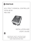
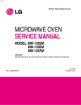
DISASSEMBLY AND ASSEMBLY
6. To remove control panel assembly
(1) Remove a screw which secure the control panel assembly to
the oven front plate. At the same time, draw forward the control panel
assembly from the oven front plate.
(2) Remove the dial knob.
(3) Remove nine screws which secure the main and
sub PCB assembly to control panel.
(4) Remove buttons.
(5) Remove the window display and decorator panel.
REF NO.
PART CODE
PART NAME
DESCRIPTION
QTY
REMARK
B 01
3511602400
D EC O R ATO R C -PA NE L
A BS
1
B 02
3515501200
W IN DO W D IS P LAY
P M M A IF-850
1
B 03
3516715110
C O N TR O L-PA N E L
A BS
1
B 04
3516906000
B UTTO N FUN CTIO N
A BS
1
B 05
3516905900
B UTTO N FUN CTIO N
A BS
1
KO R-816
B 06
3516905800
B UTTO N S TA RT
A BS
1
KO R-816
B 07
3516906100
B UTTO N FUN CTIO N
A BS
1
B 08
B 09
PK BP M S Q 200
P C B SU B A S
K O C -970T/980T
1
PK M P M S Q 200
P C B M A IN A S
K O C -970T1S
1
PK M P M S Q 230
P C B M A IN A S
K O C -970T2S
1
PK M P M S YA 00
P C B M A IN A S
K O C 980T10S
1
PK M P M S YA 00
P C B M A IN A S
K O C 980T20S
1
T2S PAN 3x8 MFZN
9
ABS
1
B10
7121300811
SCREW TAPPING
B11
3513403810
KNOB VOLUME
SM O G
KOR-816