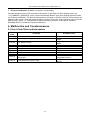
1
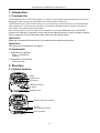
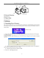
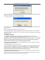
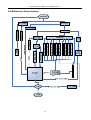
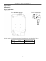
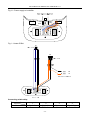
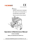
®
RESmart Auto CPAP/CPAP System
Service Manual
Service Manual for RESmart Auto CPAP/CPAP V1.1
Table of Contents
1. Introduction............................................................................................................................................................ 1
1.1 Intended Use .................................................................................................................................................. 1
I.2 Implements ..................................................................................................................................................... 1
2. Structure................................................................................................................................................................. 1
2.1 System Features ............................................................................................................................................. 1
2.2 Internal Structure ........................................................................................................................................... 2
2.3 Spare Parts ..................................................................................................................................................... 2
3. Software ................................................................................................................................................................. 2
3.1 Upgrading Device Firmware ......................................................................................................................... 2
3.2 Hidden Function ............................................................................................................................................ 3
4. Malfunction and Countermeasure ...................................................................................................................... 4
4.1 Error Code Table and Information ................................................................................................................. 4
4.2 Malfunction Determination............................................................................................................................ 5
Appendices ................................................................................................................................................................ 6
Appendix A:......................................................................................................................................................... 6
Device Configuration ................................................................................................................................ 6
1. Main device ..................................................................................................................................... 6
2. Humidifier........................................................................................................................................ 8
Components Illumination ....................................................................................................................... 10
1. Device Inside ................................................................................................................................. 10
2. Device Outside............................................................................................................................... 12
3. Humidifier...................................................................................................................................... 13
Appendix B:....................................................................................................................................................... 13
Spare Parts Configuration ..................................................................................................................... 13
Spare Parts List ....................................................................................................................................................... 16
Service Manual for RESmart Auto CPAP/CPAP V1.1
IMPORTANT
All data in this manual have been verified correctly. It is sufficient for servicing and repairing
this device. If applying this manual on other purpose, the validation should be confirmed by
BMC Medical Co., Ltd. Otherwise, BMC Medical Co., Ltd. has no responsibility for the result.
All information in this manual is protected by law and regulation. All copyrights belong to
BMC Medical Co., Ltd.
IMPORTANT, CAUTIONS and WARNINGS in this manual are to emphasize dangers to service
people.
WARNING: If operate improperly, it may cause damage to people and environment.
CAUTION: If operate improperly, it may cause damage to instrument.
IMPORTANT: Important information for servicing and repairing.
Safety Notice
Electric Shock
There is high voltage over 100VAC inside this device, please be sure to repair the device after power
off.
Chemical Safety
There may be risk of harmful bacteria and viruses after using by patient, please clean the device or
wear protective glove before servicing and repairing.
Please wash your hands with disinfectant after operating the device.
Please deal with the waste according to your local regulation.
Service Manual for RESmart Auto CPAP/CPAP V1.1
1. Introduction
1.1 Intended Use
The RESmart® Auto CPAP/CPAP system is a CPAP (Continuous Positive Airway Pressure) device
designed for the treatment of adult Obstructive Sleep Apnea (OSA) only.
The RESmart® Auto CPAP/CPAP system is to be used only on the instruction of a licensed health
care professional. Your home care provider will configure suitable pressure settings according to
your health care professional’s prescription.
This service manual is used to help service engineers to maintain RESmart® Auto CPAP/CPAP
system more efficiently. Instructions in this manual may help the device to work in the best condition.
Service engineers can find instructions they need from this manual quickly.
IMPORTANT!
Read and understand the instructions in this manual before operating the device.
IMPORTANT!
This device is not intended for life support.
I.2 Implements
1. Implements for repairing
Type ‘+’ screwdriver
Pincers
2. Implements for measuring
Pressure meter
2. Structure
2.1 System Features
Handle
Display Screen
User Buttons
Humidifier Controller
Air Outlet
Humidifier Power
Medical Product Note (bottom)
AC Inlet
Communication Connector
Filter Cap & Filter
1/17
Service Manual for RESmart Auto CPAP/CPAP V1.1
Indicator
Light
Outlet Port
Heater
Plate
Fill Line
Water Chamber
2.2 Internal Structure
See Appendix A
2.3 Spare Parts
See Appendix B
3. Software
3.1 Upgrading Device Firmware
Note: Once the RESmart® Auto CPAP/CPAP device is powered on, the LED display screen will show
the software version of the device as the following picture. Please remember the software version in
the red frame.
1. Power off the RESmart® Auto CPAP/CPAP device, and then connect the device to PC through
the USB data cable.
2. Run the software “BMC RESmart Auto CPAP/CPAP Tools for Upgrad” from PC and it will display
as below:
a) Select the upgrade file which has same suffix letter as the machine version. (For example V
ersion 1.88-AL should choose file name 1.98-AL)
b) Select the right serial port, default is COM1.
3. Click “OK”, it will display as below:
2/17
Service Manual for RESmart Auto CPAP/CPAP V1.1
Power on the RESmart® Auto CPAP/CPAP device. If the device is turned on at the beginning, please
power off the device and turn on again 5 seconds later.
4. After the device is turned on, it will display as below:
Click “Upgrade” to start. If succeeded, the right version number will be displayed on display screen
when powered on.
Note: If the upgrade failed, please repeat above steps 1-4.
If “Error 08” displayed after firmware upgrading, it means unmatched firmware used (for example:
applied CPAP firmware to RESmart® Auto CPAP device). In this case, please apply correct firmware
and upgrade again.
3.2 Hidden Function
1. Humidifier matching and dis-matching (This is automatically for the device, if the
humidifier is not working properly, perform this operation.) (Available on version 1.19 and later)
Assemble humidifier on main device, without water chamber. Enter the maintenance menu, and set
Ramp=40, then press Heated Humidifier Button when the Init P appears. Thus the humidifier is
matched. When ‘OK’ appears on screen, humidifier matching succeeded.
If cut the power supply after pressing ‘Pressure Start/Stop Button’ when the humidifier is matching,
the humidifier will be dis-matched.
2. Reset (Available on version 1.28 and later)
Press and hold the Ramp Button until the user menu appears (about 3 seconds) when the device is
on standby, press +/- User Buttons to access the Date Setting, set ‘YYYY/MM/DD’=’2097/07/01’,
then press ‘Pressure Start/Stop Button’ when ‘Hour’ setting appears, thus all device settings and
therapy records (doesn’t include Use Days and Use Time) will be reset.
If set ‘Minute’=’16’ during the above procedure, then not only device settings and therapy records,
but also patient information will be reset.
If set ‘Minute’=’26’ during the above procedure, then not only device settings, therapy records and
patient information, but also Use Days and Use Time will be reset.
3/17
Service Manual for RESmart Auto CPAP/CPAP V1.1
3. Pressure calibration (Available on version 1.58 and later)
Connect pressure meter to the air outlet of the device, in the Date and Time Setting menu, set
‘YYYY/MM/DD’=’2098/08/18’, press ‘Pressure Start/Stop Button’ when Hour Setting appears to start
the Pressure Calibration. The device output pressure is based on 20 hPa (cmH2O), and a number will
appear on the screen, when the output pressure is stable, if the value on the pressure meter is not 20
hPa (cmH2O), press ‘+/-’ User Buttons to adjust the output pressure , finally press ‘Pressure
Start/Stop Button’ to finish the Pressure Calibration.
4. Malfunction and Countermeasure
4.1 Error Code Table and Information
Error
Index
Error01
Over temperature inside or temperature sensor fault
Error02
Motor stops working
Error03
Low speed of motor
Error04
Error07
Error08
Error09
Error12
Error13
Low temperature inside
Pressure sensor fault
Wrong firmware version
Host parameter error
Over temperature inside or flowrate sensor fault
Temperature below 0°C or flowrate sensor fault
The motor is over temperature or motor temperature
sensor fault
Error14
Error15
Problems
Probable Cause
Motor temperature sensor fault
4/17
Malfunction on main board
Malfunction on motor or main
board
Malfunction on motor or main
board
Malfunction on main board
Malfunction on main board
Firmware
Malfunction on main board
Malfunction on main board
Malfunction on main board
Malfunction on motor or on motor
temperature sensor
Malfunction on motor temperature
sensor
Service Manual for RESmart Auto CPAP/CPAP V1.1
4.2 Malfunction Determination
5/17
Service Manual for RESmart Auto CPAP/CPAP V1.1
Appendices
Appendix A:
Device Configuration
1. Main device
Fig. A - Main board (backside)
Fig. B – Outlet (left side)
Hole #1, 2 and 3 in Fig. B, connect to sensor YL via silicon rubber canal. Specified in Table 1:
Fig. B
Fig. A
Specification of canal
1
Hole #1 on sensor YL
φ2mm, Φ4mm, L12cm
Table 1
6/17
Service Manual for RESmart Auto CPAP/CPAP V1.1
Fig. C – Power PCBA (front side) Sockets figuration
Fig. D – Wire connecting on power PCBA
Fig. E – Power supply connecting
Fig. F – Power supply to humidifier
7/17
Service Manual for RESmart Auto CPAP/CPAP V1.1
Connecting relationship:
Part
1
2
D
Back of device
Fig. C: CN1
E
Fig. C: CN2
Fig. A: P24
Fig.
Blower 8-pin plug
3
4
Fig. F: Left
Fig. F: Right
Fig. A: PM
Table 2
2. Humidifier
Fig. G – Humidifier PCBA (back side)
8/17
Service Manual for RESmart Auto CPAP/CPAP V1.1
Fig. H – Power supply to humidifier
Right
Orange
Left
Black
Fig. I – Heater PCBA
Connecting relationship:
Part
Fig.
I
1
2
3
4
Fig. G: P2
Fig. G: P1
Table 3
Fig. H: Left
Fig. H: Right
9/17
Service Manual for RESmart Auto CPAP/CPAP V1.1
Components Illumination
1. Device Inside
S/N
Assembly
Figure
1
Insert humidifier locker on the shield bottom.
2
Insert humidifier power supply reed on the
shield bottom as per Fig. E and F.
3
Assemble the humidifier locker and button
spring.
4
Put fixing on the spring and fix by screw (2×
3mm*8mm).
5
Put power wire.
6
Assemble the shield back on the bottom, fix
by screw (2×3mm*8mm).
7
Assemble the foam pad (non-woven side up),
8
Insert the blower unit
9
Connect the air hole of the pressure sensor
YL on the main board with the bottom hole
(hole#1) in the front of the blower outlet with a
canal of 12 cm in length and 2 mm in
inner-diameter.
10/17
Canal to sensor YL
12cm in length
Service Manual for RESmart Auto CPAP/CPAP V1.1
10
Clean up the blower wires and wind them with
a tube. Insert the plugs into sockets PM. Put
the lead of thermistor into socket PRT on main
board. Connect the main board to 24V power
supply.
11
Draw the shield back backwards and put the
3-pin plug into the corresponding socket on its
back. Lay the main board onto the 4
supporting poles on the shield bottom and set
it into the power board via the fixing pole on
PCB and get the main board fixed.
Put blower wires on the side into the gap
between blower unit and shield bottom.
11/17
Service Manual for RESmart Auto CPAP/CPAP V1.1
2. Device Outside
S/N
Assembly
Figure
1
Put the handle in the socket of the shield cover.
2
Assemble handle fixing to handle and fix by screw
(4*3*8 mm).
3
Assemble the infrared window.
4
Assemble and fix the panel.
5
Put on the key buttons.
6
Assemble shield cover on the bottom, adjust the
position of outlet and make sure it is clamped in
the right socket.
7
Fix the shield by 4 pieces screws (M3*10 mm).
8
Stick the 4 pieces of device pads.
9
Put in the filter and assemble the cover.
12/17
Service Manual for RESmart Auto CPAP/CPAP V1.1
10
Put on all plugs if necessary (without humidifier).
3. Humidifier
S/N
Assembly
1
As per Fig. H, assemble the heater plane and
wire. Fix them by screw (3*8 mm).
2
Put springs on each of the three poles on
heater plane.
3
Assemble the scaleboard on the heater plane
and fix by screws (3*8 mm).
4
As per Table 3, assemble heater PCBA and
wires.
5
Put the humidifier inner connector on the
shield.
6
Put on light window.
7
Assemble the inner and outer shield.
8
Fix on the screws (M3*10mm).
Figure
Appendix B:
Spare Parts Configuration
S/N
Name
Quantity
13/17
Figure
Service Manual for RESmart Auto CPAP/CPAP V1.1
1
Shield Cover
1
2
Handle
1
3
Handle Fixin
2
4
Shield Bottom
1
5
Humidifier Clip
1
6
Humidifier Locker
1
7
Humidifier Fixing
1
8
Filter Cover
1
9
Shield Back
1
10
Outlet
1
14/17
Service Manual for RESmart Auto CPAP/CPAP V1.1
11
PCBA Fixing
2
12
Infrared Window
2
13
Panel
1
14
Humidifier Outer Shield
1
15
Humidifier Inner Shield
1
16
Light Window
1
17
Pole Platelet
1
18
Humidifier Power Plug
1
19
Humidifier Plug (left-up)
1
20
Humidifier Plug (left-down)
1
21
Humidifier Plug (right-up)
1
15/17
Service Manual for RESmart Auto CPAP/CPAP V1.1
22
Humidifier Plug (right-down)
1
23
Device Pad
6
24
Blower Connector
1
25
Humidifier Inner Connector
1
26
Key Button
1
27
Humidifier Scaleboard
1
28
Heater Plane Spring
3
29
Button Spring
1
Spare Parts List
Part Name
S/N
Qty
Unit
Classify
Use
Main Board PCBA
1220EP0A-2000
1
PC
PCBA
Main Device
Heater PCBA
1220HW01-1000
1
PC
PCBA
Humidifier
Power Supply PCBA
123B0048
1
PC
PCBA
Main Device
Blower Unit (TKD)
1220CP0A11130
1
PC
Assembly
Main Device
Heater Plane
1220HW0112100
1
Set
Assembly
Humidifier
Power Supply PCBA Wire
120002
1
Set
Wire
Main Device
Main Board PCBA Wire
120003
1
Set
Wire
Main Device
Silicon Rubber Canal
290001
1
PC
Assembly
Main Device
Handle
210030
1
PC
Plastic
Main Device
16/17
Service Manual for RESmart Auto CPAP/CPAP V1.1
Handle Fixing
210011
2
PC
Plastic
Main Device
Shield Bottom
210031
1
PC
Plastic
Main Device
Humidifier Clip
210004
1
PC
Plastic
Main Device
Humidifier Locker
210012
1
PC
Plastic
Main Device
Humidifier Fixing
210013
1
PC
Plastic
Main Device
Filter Cover
210005
1
PC
Plastic
Main Device
Shield Back
210006
1
PC
Plastic
Main Device
Outlet
210007
1
Set
Plastic
Main Device
PCBA Fixing
210014
2
PC
Plastic
Main Device
Infrared Window
210010
2
PC
Plastic
Main Device
Panel
210036
1
PC
Plastic
Main Device
Power Supply PCBA Fixing
210015
1
PC
Plastic
Main Device
Humidifier Outer Shield
210038
1
PC
Plastic
Humidifier
Humidifier Inner Shield
210039
1
PC
Plastic
Humidifier
Pole Platelet
Light Window
210025
210023
1
1
PC
PC
Plastic
Plastic
Humidifier
Humidifier
Button Spring
230001
1
PC
Metal
Main Device
Humidifier Scale Board
230004
1
PC
Metal
Humidifier
Heater Plane Spring
230005
3
PC
Metal
Humidifier
Humidifier Power Plug
220004
1
PC
Rubber
Main Device
Humidifier Plug (left-up)
220005
1
PC
Rubber
Main Device
Humidifier Plug (left-down)
220006
1
PC
Rubber
Main Device
Humidifier Plug (right-up)
220007
1
PC
Rubber
Main Device
Humidifier Plug (right-down)
220008
1
PC
Rubber
Main Device
Device Pad
220001
6
PC
Rubber
All
Key Button
220002
1
PC
Rubber
Main Device
Blower Connector
220003
1
PC
Rubber
Main Device
Humidifier Inner Connector
220009
1
PC
Rubber
Humidifier
Screw-1
8
PC
Screw
All
Screw-2
9
PC
Screw
All
Sunk Screw
4
PC
Screw
Main Device
17/17