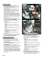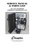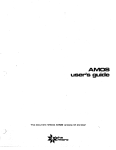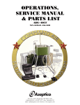
1
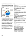
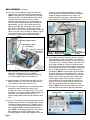
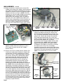
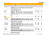
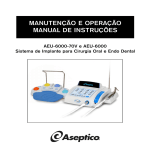
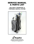
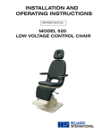
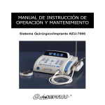
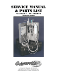
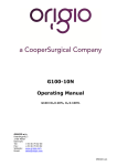
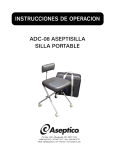
SERVICE MANUAL
& PARTS LIST
AEU-7000L-70V/7000E-70V
Implant/Endodontic Dental Systems
AEU-7000L-70V System
TABLE OF CONTENTS
General Service Information . . . . . . . . . . . . . . . . . . . . . . . . .1
Inspection & Operation Verification . . . . . . . . . . . . . . . . . . .1
Cleaning & Lubrication . . . . . . . . . . . . . . . . . . . . . . . . . . . . .2
ESD Precautions . . . . . . . . . . . . . . . . . . . . . . . . . . . . . . . . . . .2
Disassembly, Top Cover . . . . . . . . . . . . . . . . . . . . . . . . . . . . . .3
Disassembly, Chassis . . . . . . . . . . . . . . . . . . . . . . . . . . . . . . . .5
Reassembly . . . . . . . . . . . . . . . . . . . . . . . . . . . . . . . . . . . . . . . .9
Final Test Verification . . . . . . . . . . . . . . . . . . . . . . . . . . . . . .10
Motor Field Testing . . . . . . . . . . . . . . . . . . . . . . . . . . . . . . . .11
Handpiece Calibration Error Testing . . . . . . . . . . . . . . . . .12
Power PCB Testing . . . . . . . . . . . . . . . . . . . . . . . . . . . . . . . .13
Power PCB Testing Points . . . . . . . . . . . . . . . . . . . . . . . .14-16
Electrical Safety Tests . . . . . . . . . . . . . . . . . . . . . . . . . . . . . .17
Reprogramming System Software . . . . . . . . . . . . . . . . . . . .18
Reprogramming System Firmware . . . . . . . . . . . . . . . . .19-20
Sterilization Procedure . . . . . . . . . . . . . . . . . . . . . . . . . . . . .21
Maintenance & Cleaning . . . . . . . . . . . . . . . . . . . . . . . . . . .22
Specifications . . . . . . . . . . . . . . . . . . . . . . . . . . . . . . . . . . . . .22
General Troubleshooting. . . . . . . . . . . . . . . . . . . . . . . . . . . .23
Changing the Fuse . . . . . . . . . . . . . . . . . . . . . . . . . . . . . . . . .23
AEU-7000L Parts List . . . . . . . . . . . . . . . . . . . . . . . . . . .24-25
AEU-7000E Parts List . . . . . . . . . . . . . . . . . . . . . . . . . . .26-27
Symbol Definitions . . . . . . . . . . . . . . . . . . . . . . . . . . . . . . . .28
Tools List . . . . . . . . . . . . . . . . . . . . . . . . . . . . . . . . . . . . . . . .28
Warranty . . . . . . . . . . . . . . . . . . . . . . . . . . . . . . . . . . . . . . . . .29
Notes . . . . . . . . . . . . . . . . . . . . . . . . . . . . . . . . . . . . . . . . . . . .29
To prevent injury to people and damage to
property, please heed relevant warnings and
remarks. They are marked as follows:
WARNING:
Serious injury or death may
result if ignored.
NOTE:
Important additional
information and hints.
CAUTION:
Damage to property or the
environment may result if
ignored.
WARNING - RISK OF ELECTRIC SHOCK
REQUIRED QUALIFICATIONS OF SERVICE TECHNICIANS:
Persons performing repairs to active electronic circuitry or
operating High Voltage (e.g. HiPot) test equipment must have
training or experience performing similar servicing activities.
P.O. Box 1548 • Woodinville, WA 98072-1548
1-800-426-5913 • 425-487-3157 • Fax: 425-487-2608
email: [email protected] • Internet: www.aseptico.com
Page i
GENERAL SERVICE INFORMATION
This service and parts manual offers technicians information and parts lists not available in the AEU-7000L-70V or
AEU-7000E-70V Operation and Maintenance Instruction
Manuals. This manual will help you better understand
how the dental units work, thereby reducing service time.
Parts are listed and referenced to callouts in the Parts
Lists, pages 24 & 26. Use the information in the Parts List
when ordering replacement parts.
Inspection & Operation Verification
To verify that the 7000L/E units are set up and functioning
properly, refer to the set up instructions below and in their
respective Operation & Maintenance manuals. First, attach
the power cord to the back of the console and plug into a
grounded electrical outlet (see Fig. 1). NOTE: Both 7000
series units are compatible with 115VAC, 60Hz and
230VAC, 50Hz voltages and frequencies.
Figure 1
Foot Control
Connector
Main Power
ON/OFF Switch
Fuses
Power Cord
Connector
Connect the motor/cable to the receptacle on the lower
right front of the console
Figure 2 Alignment Arrows
(see Fig. 2). When
attaching the cable to unit,
align the red dot on cable
Motor
Cable
connector with the arrows
Strain
Motor
located at top center of
Relief
Cable
receptacle and bezel, and
Connector
gently push the connector
straight in to lock into place.
Remove cord by pushing inward slightly on the strain relief,
then grasping connector body near the red dot and pulling the
connector straight out of receptacle.
Attach an ‘E’ Type 20:1 handpiece to the motor, and
install the Dynamometer Adapter into the handpiece (see
Fig. 3).
Figure 3
E-TYPE
HANDPIECE
of the console and/or motor. For troubleshooting irrigation
problems relative to the pump and/or irrigation tubing,
refer to System Troubleshooting on page 20. Turn the
power switch on the rear panel of the console to the ‘On’
(-) position. The vacuum fluorescent display should show
the startup screen for a few seconds, then default to the
operating parameters of the last-used preset (or preset #1
if the factory setup was recalled). The startup screen will
display the Aseptico logo and then the software version
onboard your 7000L/E unit (see Fig. 4).
Figure 4
(Software
(Software
Version)
Press the “RATIO” Up or Down buttons to select “20:1” on
the display (see Fig. 5). Depress the foot control pedal to
verify that the motor and pump operates. Press the “CAL”
button to calibrate the 7000L/7000E handpiece/motor.
Follow the menu prompts displayed on the screen to run the
handpiece through the two-part calibration procedure (refer
to “OPERATION” section in the Operation Manual for
complete calibration instructions).
Press and hold the “SETUP” button for one second to enter
the AEU-7000L/7000E System Setup program (see Fig. 5).
Follow the menu prompts on the screen to recall the factory
setup, enable warning tones, and select other system
options (refer to “OPERATION/System Setup” section in the
Operation Manual for complete setup instructions).
Verify that the “SPEED”, “TORQUE”, “FLOW”, “PRESETS”,
and key pad navigation buttons are functioning properly
(see Fig. 5). Press each button to verify that its displayed
values and/or LEDs change accordingly (refer to
“CONTROL PANEL FUNCTIONS” section in the Operation
Manual for complete descriptions of all key pad buttons). On
the AEU-7000L unit only, press the Illumination Button (see
Fig. 5) and confirm that the LED on the handpiece
illuminates.
Figure 5
RATIO Buttons NAVIGATION Buttons
MOTOR
Version
Date)
SETUP Button
Calibration
Adapter
Attach the supplied AE-70V2 variable-speed foot control
to the connector located on the rear of the unit (see Fig.
1). The AE-23 Irrigation Tubing Set does not need to be
installed during routine maintenance and troubleshooting
CAL
Button
ILLUMINATION Button
Page 1
GENERAL SERVICE INFORMATION -
Cont’d
Depress each of the buttons on the AE-70V2 foot control to
verify that they control motor direction, turn the pump
On/Off, and step through the torque settings and presets
correctly (see Fig. 6) (refer to “VARIABLE-SPEED FOOT
CONTROL OPERATION” section in the Operation Manual
for complete instructions on setting up and operating the
foot control).
Figure 6
HANDLE (Removable)
TORQUE MODE
STEP-THROUGH
MOTOR
DIRECTION
PRESETS &
FILE SERIES
STEP-THROUGH
VARIABLE OR ON/OFF
CONTROL PEDAL
PUMP ON/OFF OR
FLOW STEP-THRU
The above procedures describe basic inspection and
verification of the AEU-7000L/7000E. If the unit performs
normally during calibration and setup, and all the key pad
buttons function properly, no further testing of the console
is needed. If the unit does not perform as required, further
diagnosis and service of system components is required.
Use the Troubleshooting sections in this manual as a
guide to diagnose problems and perform repairs.
Cleaning and Lubrication
When servicing the AEU-7000L/7000E unit, the parts of
any component disassembled should be thoroughly
cleaned and inspected before reassembly. A mild
detergent solution is an effective cleaner on all nonelectrical parts. Abrasive cleaners have the potential to
damage surface finishes and should be avoided. Any
wiping should be done with a soft lint-free cloth.
Electrical parts should be cleaned with an appropriate
electrical parts cleaner or air.
Refer to “STERILIZATION & MAINTENANCE” Sections,
pages 21 & 22, in this manual for additional cleaning
instructions.
Page 2
ESD PRECAUTIONS
The following electrostatic controls must be used when
working on this unit:
ESD Training and Standards:
Employees handling electronic sub-assemblies and ESD
sensitive components are expected to be trained.
Training should be based on IPC-A-610 or equivalent
ESD standard ANSI/ESD-S-20-20 – Protection of
Electrical and Electronic Parts, Assemblies and
Equipment.
ESD Static Controlled Area:
Areas that are designated for handling and working on
electronic sub-assemblies or their components should be
marked off with signs indicating the area where ESD
controls are to be enforced. These areas are to be kept
clear from persons that are not trained to prevent ESD
damage from occurring.
ESD Environment:
The work area is to be free of all static generating
materials, such as plastic containers, water bottles, plastic
bags, plastic objects, such as plastic pens, heat guns
(unless made for the ESD environment).
ESD Jackets:
Clothing should be non-static generating (cotton).
Static generating clothing (e.g. wool, acrylic, nylon) must
be covered with an ESD jacket that is buttoned closed.
Optional gloves:
Nitrile gloves may be used to cover the hands when
working, but are not required.
Seating:
ESD Chairs should be used in place of static generating
chairs (e.g. modern office seating use static generating
materials).
Storage and packaging:
All circuit boards and components are to be stored on or
in static dissipative or static shielding material, throughout
shipping and storage.
ESD Wrist Strap and Mat Routine Checks:
The wrist strap should be checked daily using an ESD
wrist strap testing station. See chart below.
ESD mats should be checked at least quarterly.
DISASSEMBLY
1. Turn the main power switch OFF. Unplug Power Cord,
PNs: 840079 (US) or 840078 (EURO), from AC Inlet
Connector. (NOTE: Grasp connector plug at end of
Power Cord when removing cord from Unit – do not
pull on cable.)
Figure 8
Motor Connector
Bracket Mounting
Screws & Washers (2)
Peristaltic Pump
Mounting Screws &
Lockwashers (2)
2. Remove irrigation bag and irrigation tubing sets (PNs:
AE-23) from Unit. Remove Bag Holder Rod (PN:
461541) from Unit by pulling straight up and out of
socket (see Fig. 7). Note alignment of rod pin with
keyway in socket.
3. Disconnect Motor/Cord Assembly (PN: AE-230L-40 or
AE-230M-40) and Foot Control Assembly (PN: AE70V2) from Unit (see Fig. 7). NOTE: The Motor/Cord
Assemblies and Foot Control Assembly can be
returned to Aseptico if repair services are necessary -consult Aseptico Repair Department for more
information.
Figure 7
Foot Control
Assembly
Bag Holder
Rod
Motor & Cord
Assembly
Motor Cradle
with
Dynamometer
Adapter
Motor Cradle
Motor Cradle Bracket
Motor Cradle Bracket
Mounting Screws &
Lockwashers (2)
6. Locate two screws (PN: 510406) and lock washers
(PN: 510419) that attach Motor Connector Bracket to
Chassis (see Fig. 8). Remove only the front screw
and washer with a #2 Phillips screwdriver. Loosen, but
do not remove, second screw and washer located in
slotted hole.
7. Slide Motor Connector (PN: 875073) and Bracket
backwards in slotted hole so that Connector
disengages from blue bezel in cover. Lightly tighten
mounting screw to secure Connector/Bracket in place.
8. Locate two screws (PN: 510406) and lock washers
(PN: 510419) that mount Peristaltic Pump Assembly
(PN: 330471) to Chassis (see Fig. 8). Using a #2
Phillips screwdriver, loosen but do not remove, both
screws and lock washers. Slide Pump Assembly
forward in slotted mounting holes provided.
9. Using a #2 Phillips screwdriver, remove three short
screws (PN: 510406) and lock washers (PN: 510419)
located along forward edge of Unit (see Fig. 9).
Remove four longer screws (PN: 510643) and lock
washers (PN: 510419) that attach Top Cover
subassembly to Chassis.
Figure 9
= Short Mtg. Screws
= Long Mtg. Screws
TOP COVER DISASSEMBLY:
4. Remove Motor Cradle (PN: 461561) and
Dynanometer Adapter (PN: 461558) (see Fig. 7). Turn
Unit over and gently lay face down onto padded
surface to prevent scuffing.
5. Using a #2 Phillips screwdriver, remove two screws
(PN: 510406) and lock washers (PN: 510419) that
attach Motor Cradle Bracket to Chassis (see Fig. 8).
Remove Bracket and set aside for reassembly later.
Page 3
DISASSEMBLY -
Cont’d
10. Turn Unit over and position upright on workbench.
Carefully work Top Cover subassembly off Chassis.
(NOTE: To help clear the Cover past the Pump door,
follow these steps: a) Slide Pump forward in slotted
mounting holes; b) Carefully lift Cover straight
upwards, until it disengages from Chassis base; c)
Push Pump door release button and hold Door ajar
approximately 1/4 inch - do not allow door to fully
open; d) With door ajar, manipulate Cover up and
over the rear edge of door; e) Allow Door to fully
open; then, f) Lift Cover up and off Chassis.) Rest Top
Cover on its side, next to Chassis as shown in Figure
10, taking care not to kink or sharply twist the flex
cables from Cover’s Control Panel and Display.
Figure 10
Assembly or return Display to Aseptico for repairs.
When installing a new Assembly, ensure that Display
header is properly oriented to Cover cutout. The
header should be positioned on right side of cutout
when viewing the inverted Cover from the front.)
Figure 11
Display Ribbon Cable
Control Panel Ribbon Cable
Display Ribbon Cable
(Red Stripe)
J7 “Display” Connector
J14 “Key Board”
Connector
Spacer (X4)
11. Note orientation of red stripe on Display Ribbon
Cable (PN: 870300) with Pin #1 on "Display"
connector ‘J7’, located on PCB Assembly (see Fig.
10). Detach Ribbon Cable from connector ‘J7’.
12. Note orientation of Control Panel flex cable with “Key
Board” connector ‘J14’ on PCB Assembly (see Fig.
10). Detach flex cable from connector ‘J14’.
13. Turn Top Cover subassembly over and lay face down
on protective pad. Remove four spacers (PN:
461560) from Cover if necessary (see Fig. 10). Note
orientation of red stripe on Display Ribbon Cable with
connector ‘CN3’ on Display PCB (see Fig. 11).
Detach Display Ribbon Cable and set aside for reuse
later.
14. Use a 3/16" wrench to remove two mounting nuts (PN:
510005) and split washers (PN: 510004) from Vacuum
Fluorescent Display Assembly (PN: 330503) (see Fig.
11). Carefully lift Display Assembly off the two studs
(PN: 510625) and place Assembly aside for reuse
later. (NOTE: The Display Assembly is a non serviceable component of the AEU-7000 System. If not
functioning properly, either replace Display with a new
Page 4
Display
Mounting Stud
Assembly w/Hardware (X2)
Display Ribbon
Cable Connector CN3
(Header)
15. The Display Gasket (PN: 461549), which is mounted
under the Display Filter (PN: 461548), uses doublesided adhesive backing to adhere the Filter to the Top
Cover (see Fig 12). Remove Display Filter from Cover
by pushing outwards on Filter from inside the Cover.
Push firmly with fingers until Filter pops out (take care
not to scratch Filter). Place Filter aside for reassembly
later. Peel old Gasket from face of Display housing
and discard. (NOTE: A new Gasket must be installed
each time the Filter is removed from Cover - do not
reuse an old Gasket.) To reassemble Filter and new
Gasket, remove liner from back side of Gasket and
carefully apply Gasket to housing face, aligning its
outer periphery to the raised edge on housing face
(see Fig. 12). Then, remove the other liner from the
front side of Gasket and press Display Filter onto
Gasket. (NOTE: Ensure that the inside face of Filter is
clean and free of dust before applying to adhesive.)
Figure 12
Display Gasket
Display Filter
Display
16. The Control Panel Overlay Assembly (7000L PN:
420860; 7000E PN: 420584) is attached to Top Cover
with an adhesive backing (see Fig. 13a). Removal of
the Overlay is not recommend-ed unless absolutely
necessary. If removal is required, carefully peel the
Overlay out of recess in Cover and permanently
discard entire Overlay Assembly. (NOTE: Do not
reuse an old Overlay Assembly - a detached
Overlay should always be replaced with a brand new
Assembly.) To reinstall new Overlay: 1) Insert flex
cable pigtail through the slotted hole in the Top Cover;
2) Remove liner from adhesive backing on new
Assembly; 3) Carefully center new Assembly in recess
in Top Cover; and, 4) Press down evenly on Assembly
until firmly adhered to Cover. On the underside of the
Cover, tape a loop in the Control Panel Flex Cable (do
not crease) using 2.0” of Kapton Tape (PN: 490088).
See Fig. 13b.
Figure 13a
Control Panel
Overlay
Assembly
Figure 13b
Kapton
Tape
Overlay
Flex Cable
Pigtail
Slot
In
Cover
Figure 14
Bezels
Locking Tabs
18. Cut and remove the cable tie surrounding the cable
bundle on right-hand side of PCB Assembly (see Fig.
15). Detach Pump Assembly cable connector at 'J1'
("Pump") location on PCB Assembly. Make note of
pin/wire alignments of connectors before disconnecting from PCB. Use a #2 Phillips screwdriver to
remove two Pump Assembly mounting screws (PN:
510406) and lock washers (PN: 510419) from bottom
of Chassis (see Fig. 8). Remove Pump Assembly
(PN: 330471). Remove the two Isolation Pads (PN:
461995) underneath the Pump. (NOTE: The Pump
Assembly is a non-serviceable component of AEU7000L/7000E System. If not functioning properly,
either replace with new Assembly or return Pump to
Aseptico for repairs.)
Figure 15
Pump Cable Connector
Cable
Tie
Loop
Pump
Assy
17. From the inboard side of Cover, use fingers (or pliers)
to pinch together the locking tabs of Dynamometer
Bezel (PN: 461538) and Motor Connector Bezel (PN:
461545) (see Fig. 14). Push each Bezel outward
through its respective hole in Cover. Set Bezels aside
for reuse later. (NOTE: When remounting Bezels,
ensure that locking tabs fully snap over edges of
holes, into grooves provided on inside of Cover.)
Pump Assy Mtg. Hardware (X2)
CHASSIS DISASSEMBLY:
19. Disconnect all cable and wire connectors from PCB
Assembly (7000L PN: 330575/7000E PN: 330514).
Make note of each cable’s routing and connector/pin
orientation before disconnecting from PCB (see Fig.
15). Cut and remove cable ties as necessary. Use a
Page 5
DISASSEMBLY -
Cont’d
#2 Phillips screwdriver to remove the five screws (PN:
510406), lock washers (PN: 510010), and flat washers
(PN: 510587) that attach PCB Assembly to the nylon
standoffs on Chassis. Remove PCB Assembly and set
aside for reuse later (see Fig 16) (NOTE: The PCB
Assembly is a non-serviceable component of the AEU7000L/7000E System. If not functioning properly,
replace with a new Assembly.) Use a ¼" wrench to
remove the five nylon standoffs (PN: 510626) from
Chassis. When reassembling the PCB Assembly, pull
motor wires and 48V DC wires forward and secure
them to the Chassis standoff with a tie wrap so that
the single wires cannot touch the back of the Chassis.
Figure 16
Nylon Standoff (X5)
PCB Assy
20. Locate Cable Clamp (PN: 510410) on Chassis
adjacent to Motor Connector (see Fig. 17). Use a
5/16" wrench to remove kep nut (PN: 510006).
Remove Clamp.
21. Remove screws (PN: 510406) and lock washers (PN:
510419) from slotted holes in bottom of Chassis that
connect Motor Connector subassembly to Chassis
(see Fig. 8). Use a ¾" open-ended wrench to loosen
hex nut (PN: 461970) on the inboard side of Motor
Connector Bracket (PN: 461546), which attaches
Motor Harness Assembly to Bracket (see Fig. 17).
Remove round connector nut (PN: 461969) from
outboard side of Bracket. Remove Motor Harness
Assembly (PN: 461546) from Bracket. Set Motor
Harness and Connector Bracket aside for reassembly
later. (NOTE: When reassembling Motor Connector
subassembly, insert Motor Connector from inboard
side of Bracket, outwards through Bracket cutout. Align
the flats on Connector barrel with flats on cutout and
ensure white alignment mark on Connector is positioned at the top. Apply a drop of white glue (PN: 490142)
to the Connector threads before installing round and
hex nuts. From outboard side of Bracket, thread round
nut up the barrel of Connector by hand until the white
alignment mark becomes visible, with approximately
one thread showing on face of Connector. Tighten hex
nut on the other side of the Bracket to snug Harness
Assembly up against Bracket.)
Page 6
Figure 17
Motor
Connector
Harness
Cable
Clamp
Hex
Nut
Round
Nut
White
Alignment
Mark
22. Use a 5/16" wrench to remove three nylon nuts (PN:
510745) and rubber grommets (PN: 870185) that
attach Dynamometer subassembly to Chassis (see
Fig. 18). Remove subassembly. Remove three nylon
spacers (PN: 510163) and Insulator (PN: 461979)
from underneath subassembly. Use a 5/64" Allen
wrench to loosen setscrew (PN: 510278) that secures
the Dynamometer Adapter (PN: 461540) to
Dynamometer shaft. Remove Adapter and set aside
for reassembly later. (NOTE: When reassembling
Adapter onto Dynamometer shaft, apply a drop of
Threadlocker (PN: 490053) to setscrew, then torque
the setscrew to 8-10 in.lb.) Use a #1 Phillips
screwdriver to remove four screws (PN: 510627) that
attach the Dynamometer to the Dynamometer Bracket
(PN: 461551). Remove Dynamometer from Bracket.
(NOTE: The Dynamometer is a non-serviceable
Figure 18
Dynamometer
Subassembly
Dynamometer
Rubber
Grommet
(X3)
Nylon Spacer
(X3)
Setscrew
Dynamometer
Adapter
component of the AEU-7000L/7000E System. If not
functioning properly, either replace with a new
Assembly or return it to Aseptico for repair.)
23. On the 48VDC Power Supply Assembly (PN: 840113),
detach AC Line-In Cable Assembly (PN: 875077) from
connector 'J1’, and 48V DC Cable Assembly (PN:
875076) from connector 'J2' (see Fig. 19). Make note
of pin/wire orientation before disconnecting Cables.
Use a #2 Phillips screwdriver to remove four screws
(PN: 510746), lock washers (PN: 510010), and flat
washers (PN: 510587) that attach Power Supply to
Chassis. Remove Power Supply and set aside for
reuse later. Remove Standoffs (PN: 510747). (NOTE:
The Power Supply Assembly is a non-serviceable
component of AEU-7000L/7000E System. If not
functioning properly, replace with new Assembly.)
Figure 19
Ground
Cable
Power
Supply
Assembly
AC Line-In
Cable’
Connector ‘J1’
Connector ‘J2’
spade terminals on Power Inlet Assembly (PN:
840086). Make note of wire/terminal orientation before
removing Cables. (NOTE: During reassembly, ensure
that the black wire of AC Line-In Cable is attached to
the outside terminal on Power Inlet Assembly.)
Figure 21a
Figure 21b
Fuse
Drawer
Power Inlet
Locking Tab (X5)
Assembly
25. Use a small screwdriver to detach and remove Fuse
Drawer (PN: 840060) from Power Inlet Assembly (see
Fig. 21a). Remove two Fuses (PN: 830040) from Fuse
Drawer if necessary. Press in the five locking tabs on
inboard side of Power Inlet Assembly (PN: 840086)
and push Assembly outward through cutout in back
panel of Chassis (see Fig. 21b). Set Assembly aside
for reuse later.
Figure 22
48V DC Cable
24. Locate ground stud adjacent to Power Inlet Assembly
(see Fig. 20). Use a 5/16" wrench to remove two kep
nuts (PN: 510006) and external star washers (PN:
510007) that attach Cable Clamp (part of the AC Line
In Cable) and Ground Cable Assemblies (PNs:
875075 and 875112) to stud. Detach AC Line-In Cable
(PN: 875077) and Ground Cable wire connectors from
Figure 20
AC Line-In Cable
(Black Wire To Outside
Terminal)
Ground Cable
Power Inlet
Assembly
Ground
Stud
Cable
Clamp
(Part of AC
Line-In Cable)
Port 1 & Port 2
Programming
Cables
Locking
Tabs
Footswitch
Harness
Mounting Nut
26. On outboard side of Chassis back panel, use pliers to
pinch together the two locking tabs on the sides of the
two Programming Cables (PN: 875057-01) (see Fig.
22). Push cable connectors inward through port
cutouts in Chassis, noting alignment of keyway on
bottom of connectors. Remove Cables and set aside
for reuse later.
27. Use a 13/16" wrench to remove mounting nut on
outboard side of Footswitch Harness Assembly, PN:
875074 (see Fig. 22). (NOTE: Take care to protect the
back panel against scratches when removing nut.)
Remove plastic 'D' shaped spacer, PN: 461692
(NOTE: ‘D’ shaped spacer is used on older model
units only). Push Harness Assembly inward through
'D' shaped cutout in Chassis. Note top center position
of keyway on threaded connector. Remove Harness
Assembly and set aside for reuse later. (NOTE: If
Page 7
DISASSEMBLY -
Cont’d
installing a new Footswitch Harness Assembly, and the
rubber gasket that is supplied with new Harness
Assembly is lost, Flat Washer [PN: 510648] may be
substituted. On older model units only, replace rubber
gasket with Flat Washer and 'D' shaped Spacer [PN:
461692]. See Fig. 23. When attaching the new
Harness to the Chassis, mount Flat Washer on
inboard side of Chassis and the 'D' Spacer [older
models only] on outboard side. Align tab on ‘D’
Spacer with the flat side of cutout.) Apply a drop of
white glue (PN: 490142) to the connector threads
before installing nut.
Figure 23
‘D’ Shaped Cutout
Memory Card
Dust Cover
Mounting
Nut
serviceable component of AEU-7000L/7000E System.
If not functioning properly, either replace with new
Assembly or return PCB to Aseptico for repairs.)
29. Remove Memory Card Dust Cover (PN: 461606) from
back panel of Chassis (see Fig. 23), if necessary.
30. Turn Chassis (PN: 461955-08) over to expose four
rubber Bumper Feet (PN: 850066) on bottom side
(see Fig. 25). Use a #2 Phillips screwdriver to remove
four mounting screws (PN: 510406) and washers
(PN: 510431) that attach Feet to Chassis bottom.
(NOTE: If installing new Feet, first use a #2 Phillips
screwdriver to press washers [PN: 510431] into
recess in rubber Feet [see Fig. 25 inset]. Apply a drop
of Threadlocker (PN: 490053) onto threads of screws
before mounting Feet onto Chassis.)
Figure 25
Bumper Foot
(X4)
‘D’ Shaped
Spacer
(Substituted Part on
older models only.)
Footswitch Harness
Assembly
Flat Washer
(Substituted Part
on all models.)
28. Detach Memory PCB Cable Assembly (PN: 875078)
from connector 'J2" on Memory Card PCB Assembly
(PN: 330507) (see Fig. 24). Make note of pin/wire
orientation before disconnecting. Set Cable Assembly
aside for reuse later. Use a #2 Phillips screwdriver to
remove four screws (PN: 510746), lock washers (PN:
510010), and flat washers (PN: 510587) that attach
the Memory Card PCB Assembly to Chassis. Remove
Memory Card PCB Assembly and set aside for reuse
later. Remove four Standoffs (PN: 510747). (NOTE:
The Memory Card PCB Assembly is a nonFigure 24
Memory Card
Dust Cover
Auxillary Mtg.
Hardware
Washer
Screwdriver
New Foot Installation
Before Installing New Foot,
Press Washer Into Recess
31. If necessary, use a 1/8" Allen wrench to remove two
auxillary mounting screws (PN: 510312) and washers
(PN: 510421) from bottom of Chassis (see Fig. 25).
THIS COMPLETES THE DISASSEMBLY OF THE
AEU-7000L/7000E SYSTEM.
Memory Card
PCB
Assembly
Page 8
Connector
‘J2’
Memory
PCB Cable
Assembly
REASSEMBLY
32. To reassemble the System, perform steps 1-31 above
in the reverse order.
NOTE: Follow these recommended Steps to
reassemble the Top Cover to the Chassis:
a. Prior to attaching Top Cover, loosen the two
Peristaltic Pump Assembly mounting screws.
b. Loosen only the rear mounting screw on the Motor
Connector bracket, then remove the front mounting
screw. Slide the Motor Connector backwards in the
mounting slot and lightly secure it with the rear
screw.
c. Carefully work the Top Cover down over the
Chassis and position in place but do not attach to
Chassis bottom. Ensure the flex cable from the
Control Panel is not sharply bent. Partially open the
pump door to allow the Top Cover to work past the
rear of the pump door. Work the Top Cover all the
way down until it’s properly seated against the
Chassis bottom. (Note the four plastic alignment
tabs that engage the four square holes on the
Chassis bottom.)
d. Use a #2 Phillips screwdriver to install three 3/8”
screws (PN 510406) with three lock washers (PN
510419), and four longer 2½” screws (PN 510643)
and lock washers (PN: 510419), through the
Chassis bottom into the Top Cover, as shown on
Figure 8, page 3.
f. Reposition the Peristaltic Pump frontwards or
backwards until it just clears the Cover at the front
when opened. Tighten the two Pump mounting
screws.
g. Slide the Motor Connector forward until it protrudes
out through the blue bezel in the front of the Unit.
Reinstall the front 3/8” mounting screw (PN
510406) with lock washer (PN 510419) and tighten
both mounting screws.
h. Open and close the Pump door several times and
verify that the door opens, closes, and latches
smoothly. Readjust Pump position if necessary.
i. Connect Foot Pedal and Motor. Insert a length of
Pump tubing into the peristaltic pump (refer to
Operator’s Manual for instructions on setting up
Pump/tubing). Verify that the Pump latches
securely.
j. Power AEU-7000L/7000E Unit ‘On’.
k. With the “Flow” ‘On/Off’ button set to ‘On’ and the
Pump flow rate set to 100%, depress the Foot
Control and verify the Pump runs.
Page 9
FINAL TEST VERIFICATION
1. Verify fuse values. Fuses should be 1.6A 250V SLOBLO (830040).
2. Check the console for physical imperfections. Verify
that the Foot Switch and Motor connectors are tight by
connecting the relevant cable and attempting to twist
the connector to the left and right by hand.
3. Perform Electrical Safety Tests: Refer to page 17 for
complete instructions on performing the Electrical
Safety Tests on the AEU-7000L and AEU-7000E
units.
4. Connect field programmer AFP-01 to Programming
Port 1 at the rear of the console. Insert memory card
containing Master Code Firmware PN 890048 (7000L)
or PN 890022 (7000E) into the AFP-01. Turn on the
AFP-01 and wait for the programming process to
complete. (Refer to pages 19 & 20 for complete
Master Code Firmware programming instructions.)
5. Connect field programmer AFP-01 to Programming
Port 2 at the rear of the console. Insert memory card
containing Slave Code Firmware PN 890049 (7000L)
or PN 890023 (7000E) into the AFP-01. Turn on the
AFP-01 and wait for the programming process to
complete. (Refer to pages 19 & 20 for complete
Slave Code Firmware programming instructions.)
6. Insert System Software memory card PN MC-7000L or
PN MC-7000E into the Memory Card Port at the rear
of the console. Connect a power cord to the console.
Turn the console power switch on and follow the onscreen prompts to program the console. Verify that the
programming process completed successfully and that
the software version displayed at console startup was
correct. (Refer to page 18 for complete System
Software programming instructions.)
7. Verify that the motor and calibration systems are
functional:
7.1. Attach an AE-230L-40 (7000L) or AE-230M-40
(7000E) motor with a 20:1 handpiece and an AE7PM foot control to the console.
7.2. Use Ratio keys to set Ratio to 20:1 on the display.
Depress the footswitch and verify that the motor
runs. Press the CAL button and follow the onscreen prompts to complete the calibration
process, verifying that the calibration completed
successfully. If calibration fails, refer to page 12
for Calibration Error Testing instructions.
7.3. Press the SELECT button to enter “Endo Mode”.
Use the Ratio keys to set the handpiece ratio to
8:1. Attach an 8:1 handpiece to the motor. Press
the CAL button and follow the on-screen prompts
to complete the calibration process, verifying that
the calibration completed successfully. If
calibration fails, refer to page 12 for Calibration
Error Testing instructions. Press the SELECT
button again to return to “Implant Mode”.
Page 10
8. Connect an AE-70V2 foot control and depress each of
the buttons. Verify that the function of each switch is
(from lower left, clockwise): Preset Increment, Motor
direction, Torque Increment, Flow ON/OFF. Select
Preset 1. Press on the variable pedal and verify that
the motor operates in proportion to the pedal position.
(Refer to Operator’s Manual for complete
instructions on installing and using the AE-70V2
foot control.)
9. Change the motor direction to reverse. Press and hold
the footswitch for several seconds and verify that the
motor runs and that the console audible indicator
beeps consistently.
10.Open and close the pump door several times and
verify that the door opens, closes, and latches
smoothly. Insert a length of pump tubing into the
peristaltic pump and verify that the pump latches
securely. With the flow set to 100% depress the
footswitch and verify that the pump runs smoothly.
11. 7000L UNIT ONLY: Verify operation of the hand motor
light and associated user interface functionality:
11.1. Press the LIGHT button to turn the keypad light
LED off. Press the footpedal and verify that the
hand motor light stays off.
11.2. Press the LIGHT button to turn the keypad light
LED on. Press the footpedal and verify that the
hand motor light turns on.
12.Verify operation and tactile feedback of the keypad
buttons: (Refer to Operator’s Manual for complete
instructions on using the unit’s control panel).
12.1. Press the RATIO UP and RATIO DOWN buttons,
verifying that the displayed ratio changes with
each press.
12.2. Press the SPEED UP and SPEED DOWN
buttons, verifying that the displayed speed
changes with each press.
12.3. Press the FWD/REV button repeatedly and verify
that the FWD and REV LEDs change with each
press.
12.4. Press the TORQUE UP and TORQUE DOWN
buttons, verifying that the displayed torque
changes with each press.
12.5. Press the FLOW ON/OFF button repeatedly to
turn the pump off and then back on, and verify
that the green FLOW ON LED illuminates. Press
the FLOW UP and FLOW DOWN buttons,
verifying that the displayed flow setting changes
with each press.
12.6. Set Ratio to 20:1. Press the AS/MAX button
repeatedly and verify that the A-S and MAX
LEDs illuminate.
12.7. Press each of the preset buttons and verify that
the LED for each preset button illuminates.
12.8. Press the blue standby button and verify that the
display goes blank. Press the standby button
again to reactivate the display.
12.9. Press and hold Preset 1. Answer ‘YES’ to save
the settings. Answer ‘YES’ to edit the label. Use
the left and right arrow keys and verify that the
cursor moves. Use the up (YES) and down (NO)
keys and verify that the letters change. Press
INSERT and DELETE keys and verify that
spaces are added or deleted with each press.
Press the SELECT button to save the label
changes.
13.Restore the factory defaults by pressing and holding
the SETUP button, then answering ‘YES’ to the
prompts.
14.Turn off console and unplug.
15.Scuff oval recess on front surface of housing with
Scotch-Brite pad to remove gloss from plastic. Wipe
clean with alcohol and soft cloth. When dry, place oval
dome label in recess and press down firmly.
16.Apply Serial Number Label 420556-02 to the bottom of
the Chassis as shown on Sheet 4.
MOTOR FIELD TESTING
NOTE: AEU-7000L/7000E motor testing in the field is
limited to simple manual and visual tests that help to
determine the source of the problem.
1. Motor Rotation Test: This test can be performed
manually using a simple motor-rotation tool that can
be improvised in the field or procured from Aseptico
(ref. PN AE-43). The tool needs to be able to grasp
the motor’s internal rotor/magnet assembly and rotate
it to determine if the assembly is damaged. Insert tool
into motor tip and engage rotor shaft as shown in Figs.
26A & 26C. Turn tool back and forth to determine if
rotor assembly moves freely (Fig. 26C). If resistance is
felt, return motor/cord assembly to Aseptico for repair.
Figure 26A - Motor Rotation Tool
Figure 26B - Motor Internals
Figure 26C - Rotor Rotation Test
Rotate
Test Tool
Page 11
HANDPIECE CALIBRATION ERROR TESTING
NOTE: This section provides troubleshooting
procedures for the “Calibration Failed !” error message
which displays if the AEU-7000L/7000E motor fails
during the handpiece “Free Run” calibration test (refer
to Operation Manual for complete handpiece
calibration instructions). This information will help
determine if the source of the problem is in the motor,
handpiece, or the unit console.
1. Turn AEU-7000L/7000E unit ‘On’. The Startup screen
will appear.
2. Preselect ratio of the handpiece using the Ratio
Up/Down buttons on the console keypad.
3. Press ‘CAL’ button to enter the calibration test. A
prompt will instruct the user to install the handpiece
onto the motor. Insert a dynamometer adapter, bur, or
bit into the handpiece. Press “Next”. The System will
automatically run the handpiece through the “Free
Figure 27 - Motor/Handpiece Troubleshooting
Page 12
Run” test on either increaser or reduction type
handpieces. The message “Free Run In Progress /
Please Wait...” will display
4. If the motor or handpiece is malfunctioning, jammed or
disconnected, the “Calibration Failed ! message will
display. Consult the troubleshooting chart below to
pinpoint the problem.
NOTE: The AEU-7000L/7000E power PCB board may
be the source of the problem. For troubleshooting
procedures specific to the PCB board, refer to the PCB
testing chart on page 13. Before replacing PCB board,
try calibrating unit with a new, fully operational motor,
to help isolate the board as the problem.
6. If the motor, handpiece, and console are functioning
properly, the message “Calibration Successful !” will
display.
POWER PCB TESTING
If the AEU-7000L/7000E fails to start properly, use this
flowchart to pinpoint the problem. This flowchart
provides additional troubleshooting procedures for the
unit’s main power printed circuit board (PCB).
NOTE: If the power PCB is replaced, the unit’s software
must be reprogrammed (refer to page 19). For
troubleshooting procedures specific to the motor, refer
to the motor testing chart on page 12.
Figure 28 - Power PCB Troubleshooting
Page 13
POWER PCB TESTING POINTS
WARNING
Dangerous voltages are present during the following
board testing. Severe electric shock can result and
could prove fatal. Only qualified technicians should
perform these tests.
1. Turn AEU-7000L/7000E power switch ‘Off’. Remove
irrigation bag, tubing, and rod. Disconnect motor/cable
and foot control. Disassemble top cover from chassis
(refer to page 3). Place unit upright on work bench to
expose internal Power PCB.
2. 120V (US) or 230V (International) AC Check: This
test verifies that the fuses are good and the proper AC
voltage is being provided to the power PCB circuit.
Connect voltmeter test leads to contacts as indicated in
AC Voltage Ref. ‘A’, Figs. 29A&B. Turn AEU7000L/7000E power switch ‘On’ .
CAUTION: High voltages present - only qualified
technicians should perform this test. Use extreme
caution to avoid severe electric shock.
If 120V(+/-10V) (US) or 230V(+/-15V) (Internatonal) AC
is not present, check power switch and fuses first, then
if proper voltage still not present, replace Power
Inlet/Fuse Holder assembly.
Turn AEU-7000L/7000E power switch ‘Off’ after 120V
or 230V AC test is completed.
3. 48V DC Check: This test verifies that proper DC voltage
is being provided to the power PCB circuit. Connect
voltmeter test leads to contacts as indicated in DC
Voltage Reference ‘B’, Figs. 29A&B. Turn AEU7000L/7000E power switch ‘On’.
CAUTION: High voltages present - only qualified
technicians should perform this test. Use extreme
caution to avoid severe electric shock.
If 48V(+/-1.0V) DC is not present:
a. Disconnect 48VDC Cable from Power PCB
connector ‘J2’.
b. Check 48VDC Cable output from DC Power Supply
for 48VDC(+/-1.0V).
c. If 48VDC(+/-1.0V) Supply output is not present,
replace Power Supply. If 48VDC output is present
from Supply, replace PCB board.
Turn AEU-7000L/7000E power switch ‘Off’ after 48VDC
test is completed.
Page 14
4. 5V DC Check: This test verifies that proper DC
voltage is being provided to the key pad, foot pedal,
flash card, programming ports, and other PCB
components. Connect voltmeter test leads to contacts
as indicated in DC Voltage Reference ‘C’, Figs.
29A&B. Turn AEU-7000 power switch ‘On’.
CAUTION: High voltages present - only qualified
technicians should perform this test. Use extreme
caution to avoid severe electric shock.
Replace PCB board if 5V(+/-0.2V) DC is not present.
Turn AEU-7000L/7000E power switch ‘Off’ after 5VDC
test is completed.
5. 2.5V DC Check: This test verifies that proper DC
voltage is being provided to the motor and other PCB
components. Connect voltmeter test leads to contacts
as indicated in DC Voltage Reference ‘D’, Figs.
29A&B. Turn AEU-7000L/7000E power switch ‘On’.
CAUTION: High voltages present - only qualified
technicians should perform this test. Use extreme
caution to avoid severe electric shock.
Replace PCB board if 2.5V(+/-0.2V) DC is not present.
Turn AEU-7000L/7000E power switch ‘Off’ after
2.5VDC test is completed.
6. 15V DC Check: This test verifies that proper DC
voltage is being provided to the motor and other PCB
components. Connect voltmeter test leads to contacts
as indicated in DC Voltage Reference ‘E’, Figs.
29A&B. Turn AEU-7000L/7000E power switch ‘On’.
CAUTION: High voltages present - only qualified
technicians should perform this test. Use extreme
caution to avoid severe electric shock.
Replace PCB board if 15V(+/-1.0V) DC is not present.
Turn AEU-7000L/7000E power switch ‘Off’ after 15VDC
test is completed.
IMPORTANT
The Power PCB is a non-serviceable component of
the AEU-7000L/7000E Systems. If not functioning
properly the PCB should either be replaced with a
new Assembly or returned to Aseptico for repairs.
OR
INTERNATIONAL
AC VOLTAGE:
Figure 29A - AEU-7000L Power PCB Test Points
Page 15
AEU-7000E
POWER PCB
ASSEMBLY
OR
Page 16
AC INLET
WIRING ASSEMBLY
INTERNATIONAL
AC VOLTAGE:
Figure 29B - AEU-7000E Power PCB Test Points
ELECTRICAL SAFETY TESTS
WARNING
Dangerous voltages are present during the following
Hi-Pot testing. Severe electric shock can result and
could prove fatal. Only qualified technicians should
perform these tests.
Whenever repairs on any AEU-7000L/7000E unit
involves safety issues, such as electrical malfunctions or
changeout of critical components in the electrical circuit,
i.e., main power board or transformer, it is recommended
that the Hi-Pot and/or Ground Bond Safety Tests below
be performed after repairs are completed. If the technician determines that Safety Tests are required, the tests
should consist of three separate tests, typically performed
in tandem via a single Hi-Pot test/measurement device:
1. Perform Electrical Safety Tests:
1.1. Attach an AE-230L-40 motor (7000L) or an AE230M-40 motor (7000E) to the unit console.
1.2. Conduct a Ground Bond Test between Earth
Ground at the power inlet and the chassis at the
pump drain opening (see Fig. 30). Test
parameters are 25 Amps for two seconds with
an allowed resistance of no more than 0.1
Ohms.
1.3. Conduct a Dielectric Withstand Test between
Mains at the power inlet and the pump drain
opening (see Fig. 30). Perform test with the
power inlet switch in the “ON” position. Test
parameters are 2520 VDC for one second with
an allowed leakage current of 1.0mA.
1.4. Conduct a Dielectric Withstand Test between
Mains at the power inlet and the motor housing
(see Fig. 31). Test is to be performed with the
power inlet switch in the “ON” position and the
return lead of the test equipment connected to
the E-coupling of the motor body. Test
parameters are 4250 VDC for one second with
an allowed leakage current of 1.0mA.
2. Using a multimeter (Amprobe 38XR-A or equivalent
meter with 0.01nF resolution), measure the
capacitance between the sheet metal chassis of the
console and the DC return pin (Pin #4) of the
footswitch connector (see Fig. 32). Result is
acceptable if the capacitance measured is 5.3-8.0
nF.
IMPORTANT: Any system that fails any of the
above tests must be removed from service and
thoroughly examined, repaired and retested by a
qualified technician.
Figure 30
RETURN LEAD TO
PUMP DRAIN OPENING
Figure 31
Figure 32
MEASURE
BETWEEN
CHASSIS AND
PIN#4
NOTE: Although Aseptico uses the Associated
Research, Inc. Model 7564SA Hipot/Ground Tester
for these tests, alternative equipment with
equivalent setup and testing specifications may be
used. Ensure that the above test parameters are
set up correctly before conducting the tests.
Page 17
REPROGRAMMING SYSTEM SOFTWARE
Figure 33
MEMORY
CARD
DUST
COVER
Each System has the ability to load software updates
and enhance its functionality, should this be desired. A
card slot, labeled “Memory Card Port”, is provided on
the back of each unit (see Fig. 33). This Port accepts
memory cards, PN’s MC-7000L (7000L) or MC-7000E
(7000E), which are very similar to those used in
common consumer devices. These cards, available
from Aseptico, enable a user to update software or
replace existing software that might have been
accidentally erased or corrupted. Contact Aseptico for
more information on card usage and availability. To
reprogram a unit, follow the Steps below:
Programming Steps:
1. Turn ‘Off’ the Main Power Switch on the back panel.
2. Grasp the right-hand end of the rubber dust cover for
the Memory Card Port and pry open the cover to
expose the card slot.
3. Insert the new MC-7000L or MC-7000E memory card
into the slot with label facing upward (card terminals
should face downward). Carefully and slowly press
card inward until a ‘click’ is felt, then release the card.
4. Turn the Main Power Switch (on the back panel) ‘On’.
Page 18
5. The Display will show the following message:
Memory Card Detected.
Re-program? (Yes / No)
• Press the ‘Yes’ key on the Control Panel.
6. The Display will then show the following message:
Presets will be erased!
Continue? (Yes / No)
• Press the ‘Yes’ key on the Control Panel.
7. The Display will show the following message:
Programming...
• A status bar will indicate the progress of the
programming.
8. When the programming is complete, the Display will
show the following message:
Programming successful.
Eject card.
• Press the card inward slightly, then release it to eject it.
When the card is ejected, the System will reset with
normal power-up screen displayed.
9. Remove the memory card and store it in a safe place.
Close the rubber dust cover on the Memory Card
Port.
In the event that the programming procedure is
interrupted, the unit will display the following
message:
Then:
Programming Failed
Console Software Error.
Re-program unit.
Re-start the programming procedure from Step #1
(Remember to turn main power ‘Off’ before
reprogramming).
REPROGRAMMING SYSTEM FIRMWARE
The AEU-7000L/7000E Units’ internal components are
controlled by three software microchips. The software in
these chips can be updated or replaced by using the AFP01 Field Programmer (see Fig. 34) to upload the new
firmware directly into the microcontrollers. Refer to the
firmware below and its respective programming port when
uploading:
A. Master Code Firmware (Port 1):
7000L: PN 890048
7000E: PN 890022
B. Slave Code Firmware (Port 2):
7000L: PN 890049
7000E: PN 890023
C. Motor Driver Firmware (J1 Connector):
7000L & 7000E: PN 890021
Contact Aseptico for availability on the latest firmware.
Follow the appropriate steps below to reprogram the
microcontrollers:
A. Master Code Firmware
1. Turn Off all power to the AEU-7000L/E Units.
2. Turn Off the programming switch within the AFP-01
Field Programmer (see Fig. 35).
3. Install battery into AFP-01 Field Programmer, as
shown in Figure 35.
4. Install Master Card, PN: 890048 (7000L) or PN:
890022 (7000E), into the card holder located on
Programmer PCB (see Fig. 35).
5. Insert the 4-pin square connector (for an HC08
Microcontroller) into the programming Port-1 on the
back of the Unit, making sure that the connector
latch is properly oriented with the mating connector.
6. Turn On the programming switch within the AFP-01
Programmer.
7. The Green & Red LED’s on the Programmer will
operate in the following sequence when
programming is successful: IMPORTANT: The Red
LED will remain On in the event of improper
programming.
• Green & Red LED’s turn On for approx. one
second.
• Green & Red LED’s turn Off for approx. one
second.
• Green & Red LED’s again turn On for approx. one
second.
• Green & Red LED’s again turn Off for approx. one
second.
• Green LED remains On for about two seconds.
• Green LED flashes On and off during
programming.
• Green LED remains On at the completion of
programming.
8. Turn Off the programming switch within the AFP-01
Programmer and remove the connector from Unit.
Master Code Programming is completed.
Figure 34
AFP-01
Field Programmer
AEU-7000L/E
9V Battery
Firmware
Cards
(Sold
Separately)
Figure 35
Green
LED
On/Off Switch
(Shown in ‘On’ Position)
Port-1
Firmware
Card
(Master Code)
Figure 36
Green
LED
On/Off Switch
(Shown in ‘On’ Position)
Port-2
Firmware
Card
(Slave Code)
Page 19
B. Slave Code Firmware
1. Turn Off all power to the AEU-7000L/E Units.
2. Turn Off the programming switch within the AFP-01
Field Programmer (see Fig. 36).
3. Install battery into AFP-01 Field Programmer, as
shown in Figure 36.
4. Install Slave Card, PN: 890049 (7000L) or PN:
890023 (7000E), into the card holder located on
Programmer PCB (see Fig. 36).
5. Insert the 4-pin square connector (for an HC08
Microcontroller) into the programming Port-2 on the
back of the Unit, making sure that the connector
latch is properly oriented with the mating connector.
6. Turn On the programming switch within the AFP-01
Programmer.
7. The Green & Red LED’s on the Programmer will
operate in the following sequence when
programming is successful: IMPORTANT: The Red
LED will remain On in the event of improper
programming.
• Green & Red LED’s turn On for approx. one
second.
• Green & Red LED’s turn Off for approx. one
second.
• Green & Red LED’s again turn On for approx. one
second.
• Green & Red LED’s again turn Off for approx. one
second.
• Green LED remains On for about two seconds.
• Green LED flashes On and off during
programming.
• Green LED remains On at the completion of
programming.
8. Turn Off the programming switch within the AFP-01
Programmer and remove the connector from Unit.
Slave Code Programming is completed.
C. Stepper Motor Driver Firmware
1. Turn Off all power to the AEU-7000L/E Units.
2. Remove top cover from Unit (refer to page 3).
3. Disconnect Display ribbon cable from power PCB
board (see Fig. 37).
4. Turn Off the programming switch within the AFP-01
Field Programmer (see Fig. 38).
5. Install battery into AFP-01 Field Programmer, as
shown in Figure 38.
6. Install Motor Driver Card, PN: 890021, into the card
holder located on Programmer PCB (see Fig. 38).
7. Insert the white 4-pin in-line connector into the
programming connector ‘J1’ on the motor module
(see Figs. 37 & 38), making sure that the connector
latch is properly oriented with the mating connector.
8. Turn On the programming switch within the AFP-01
Programmer.
Page 20
Figure 37
‘J1’
Connector
Stepper Motor
Module
Display Cable
(Disconnect before
Programming)
Figure 38
On/Off Switch
(Shown in ‘On’ Position)
Green
LED
‘J1’
Connector
Firmware Card
(Motor Driver)
9. The Green & Red LED’s on the Programmer will
operate in the following sequence when
programming is successful: IMPORTANT: The Red
LED will remain On in the event of improper
programming.
• Green & Red LED’s turn On for approx. one
second.
• Green & Red LED’s turn Off for approx. one
second.
• Green & Red LED’s again turn On for approx. one
second.
• Green & Red LED’s again turn Off for approx. one
second.
• Green LED remains On for about two seconds.
• Green LED flashes On and off during
programming.
• Green LED remains On at the completion of
programming.
10.Turn Off the programming switch within the
Programmer and remove the connector from Unit.
11. Reconnect Display ribbon Cable. Reattach Cover.
Motor Driver Programming is completed.
STERILIZATION PROCEDURES:
WARNING - Sterilize the motor between each
patient use.
WARNING - Use of a sterilization method or
temperatures other than what are prescribed
may damage the motor or present a risk of
cross-contamination between patients.
CAUTION - Do not soak or submerge the motor
in any liquid.
Motor & Cord Assembly:
The entire motor and cord assembly is fully
autoclavable. Loosely coil the motor cord when
autoclaving. Avoid sharply bending the cord when
autoclaving.
Fig.39
MOTOR & CORD STERILIZATION
STERILIZATION:
Pre-clean
1) Brush off any visible signs of debris from the
motor and cord.
2) Thoroughly clean the device with a moist cloth or
towel to remove any remaining signs of debris.
Sterilize
3) Select one of the three following sterilization
methods (A. B. or C.):
The entire motor &
cord assembly is
autoclavable.
NOTE: Call Aseptico Inc. at 1-800-426-5913 for any
questions or clarifications on this sterilization
procedure.
Wrapped Sterilization – Place in an appropriately
sized sterilization pouch and seal it.
A. Standard autoclaving (Gravity displacement
method)
Time: 15 min
Temperature: 132° C (270° F)
Dry time: 30 minutes
B. Pre-vacuum (dynamic-air-removal)
Time: 4 minutes
Temperature: 132° C (270° F)
Dry time: 40 minutes
Flash Sterilization – For immediate use only.
C. Unwrapped standard autoclaving (Gravity
displacement method)
Time: 10 minutes
Temperature: 132° C (270° F)
No dry time is required for flash sterilization.
Page 21
MAINTENANCE & CLEANING:
HANDPIECES - Thorough cleaning and lubrication of
handpieces after each use and before sterilization is very
important to ensure proper operation and service life of the
handpiece. Follow the instructions provided with the
handpiece for complete maintenance instructions.
MOTOR - IMPORTANT! Protect motor
from excess oil draining from handpiece.
After lubricating and before autoclaving,
stand handpiece by its base on a paper
towel and allow excess oil to drain (see
Figure 40).
Fig.40
WARNING
• Do not attempt to disassemble the motor or motor connector.
• Do not oil or lubricate the motor.
• Do not attach a handpiece to the motor while the motor is
running.
• Do not bend motor cord sharply.
• The motor is sensitive to shock. Do not drop or impact motor
against a hard surface.
Failure to comply with any of the above instructions may void your warranty.
AEU-7000L MOTOR LED LENS CLEANING - The lens of
the LED light on the AEU-7000L Fig.41
motor (see Fig. 41) is soft and
can be damaged. It should not
be exposed to dust and debris.
Excessive dust and debris may LED
cause a drastic decrease in
optical output. In the event that
the light requires cleaning, first
AEU-7000L MOTOR
try a gentle swabbing, using a
lint-free swab. If needed, use a lint-free swab and isopropyl
alcohol to gently remove dirt from the lens. Do not use
other solvents as they may adversely react with the LED
assembly.
SPECIFICATIONS::
Console Dimensions:
9.98"W x 9.42"L x 5.10"H
(25.3 cm x 23.9 cm x 12.9 cm)
Console Weight:
7.3 lbs (3.3 kg)
Power:
100-240V
1.1 - 0.5 A
50-60 Hz
Fuses:
1.6A, 250V, Slo-Blow Type
Duty Cycle:
16.7%
NOTE:
The appliance inlet is the mains disconnect means.
Environmental Conditions:
• Operating Temperature: 10° to 28°C (50° to 82.4°F)
• Transportation & Storage Temperature:
• -20° to 60°C (-4° to 140°F)
• Relative Humidity: 10% to 90% noncondensing
• Altitude: 0 to 3,048 meters (0 to 10,000 feet)
28°C
(82.4°F)
10°C
(50°F)
Page 22
60°C
(140°F)
1013.3
hPa
697
hPa
10%
SILICONE WATER LINES - The silicone water lines used
for the pump are fully autoclavable:
FOOT CONTROL - The exterior of the foot control may
be cleaned by wiping with a soft cloth moistened with
mild detergent or disinfecting solution. When cleaning,
remove handle from foot control and wipe clean with
disinfectant, then reinstall handle.
-20°C
(-4°F)
90%
CONSOLE - The exterior of the console may be cleaned
by wiping with a soft cloth moistened with a mild
detergent or a 1:10 bleach solution (1 part household
bleach to 10 parts water). IMPORTANT: Use of other
cleaning or disinfecting solutions may damage the
console and may void the warranty.
Pre-Cleaning: Before sterilization, run clean water
through the tubing for 30 seconds to expel any stagnant
water. NOTE: Do not use disinfectants on the tubing set.
Bacteria and viruses will be neutralized during sterilization.
Sterilization: Sterilize tubing at 132º C (270º F) for 10
minutes.
TRANSPORT &
STORAGE
TEMPERATURE
OPERATING
TEMPERATURE
41EJ
MEDICAL ELECTRIC EQUIPMENT WITH
RESPECT TO ELECTRIC SHOCK, FIRE
AND MECHANICAL HAZARDS ONLY IN
ACCORDANCE WITH UL 60601-1 (First
Edition) and CAN/CSA C22.2 No. 601.1-M90
WARNING: This device has been tested and found to comply
with the emissions requirements of IEC 60601-1-2:2001-09.
These requirements provide reasonable protection against
harmful electromagnetic interference in a typical medical
installation. However, high levels of radio-frequency (RF)
emissions from electrical devices, such as cellular phones, may
disrupt the performance of this device. To mitigate disruptive
electromagnetic interference, position this device away from RF
transmitters and other sources of electromagnetic energy.
GENERAL TROUBLESHOOTING:
Problem:
Console does not light when turned on:
Console lights when turned on, but
handpiece does not turn:
No water flow from pump to handpiece:
Irrigation tube leaks:
Motor slowing down or sluggish:
System functions displaying incorrectly:
Cannot remove motor/cord from unit:
Correction:
• Check console to power connection.
• Check fuse. If blown, replace with 1.6A/250V
slo-blow fuse.
• Check motor plug connection.
• Check foot pedal connection.
• Depress foot pedal.
• Increase RPM.
• Increase Torque setting
• Check that bur/drill is properly seated in the handpiece
and the collet is closed.
• Check that pump is on and flow level is sufficient.
• Check that water container seal is completely punctured.
• Make sure the irrigation tubing is properly installed in
pump door and flow is in the correct direction.
• Replace worn tube section located under the pump door
with a new section from the extra tube set provided with
the system.
• Check for dirty, under-lubricated handpiece.
• Check if handpiece lubricant is draining into motor. After
lubricating and before autoclaving, stand handpiece on
its base to let excess lubricant drain out.
• Verify that ratio setting matches handpiece ratio. Use
calibration function.
• Turn power switch Off, wait 5 seconds, then turn back
On to reset.
• Grasp the strain relief directly behind the cord connector
and gently push inward. Then, grasp the connector body
near the red dot and pull the connector straight out of
the receptacle.
CHANGING THE FUSE:
WARNING
Turn the power off and unplug the unit
before following the steps below.
Figure 42
1. Remove the Fuse Holder from the Power Inlet
connector (see Fig. 42).
2. Replace the fuses in the Fuse holder.
Replacement Fuses:
1.6A, 250V slo-blow fuse
(Fuse size: 5 x 20mm)
3. Reinstall the Fuse Holder.
NOTE: The AEU-7000L/7000E features auto-sensing,
global voltage compatibility. The fuse indicated is correct
for 100V-240V 50/60 Hz line voltage.
Page 23
Page 24
FINAL ASSY AE-70V2 FOOT CONTROL VAR
M/S 6/32 X 2-1/2 PNHD PH SS
VACUUM FLUORESCENT DISPLAY ASSY
14
14
WASHER EXT STAR PLTD #6
38
34
37
36
33
35
32
BRACKET CONNECTOR
NUT HEX MOTOR CONNECTOR
NUT MOTOR CONNECTOR CMPL
MOTOR HARNESS ASSY
NUT KEPS PLTD 6-32
34
31
33
30
STANDOFF 1/4 HEX #6 X 1-7/8 NYL
510587
32
29
31
461546
461970
461969
875110
510007
510006
510626
510010
WASHER STNLS NAS 620-C6 .143IDx.267OD
WASHER SPLIT PLTD #6
330575
330576
461995
330471
461547
490088
461560
461545
461538
420860
461549
461548
510625
510004
510005
330503
870300
510643
420556-02
510419
510406
461562
461561-01
461558
461541
120391-01
AE-230L-40
840079
120368
PART NO.
PCB ASSY POWER & STEPPR BRD CMPL
30
29
28
CHASSIS ASSY AEU-7000L
ISOLATION PAD PUMP BRACKET AEU-7000
PUMP ASSY PERISTALTIC
TOP COVER
TAPE KAPTON 1/4 INCH WIDE ROLL
SPACER COVER AEU-7000
BEZEL MOTOR CONNECTOR
BEZEL DYNAMOMETER
OVERLAY MEMBRANE CONTROL PNL
GASKET DISPLAY
DISPLAY FILTER
STUD PRESS
WASHER SPLIT PLTD #4
NUT HEX 4-40 SML PTN PLTD
CABLE RIBBON SOC TO SOC 14 POS
28
27
27
26
26
25
25
24
24
23
23
22
22
21
21
20
20
19
19
18
18
17
17
16
16
15
15
13
13
LABEL SERIAL NUMBER AEU-7000L
12
12
11
11
WASHER INT STAR S/S #6
M/S STNLS PHDPHL 6-32 X 3/8
BRACKET CRADLE
HANDPIECE CRADLE
ADAPTER HANDPIECE
HOLDER IRRIGANT BAG
10
10
99
88
77
66
55
MOTOR/CABLE ASSY
44
33
LINECORD WHT HOSPT GRDE 5-15PH6C
FINAL ASSY AEU-7000L
DESCRIPTION
22
11
ITEM
1
1
1
1
2
3
5
13
13
1
1
2
1
1
2"
4
1
1
1
1
1
2
2
2
1
1
4
1
13
18
1
1
1
1
1
1
1
1
Qty
NOT SHOWN
NOT SHOWN
NOT SHOWN
NOT SHOWN
NOT SHOWN
NOT SHOWN
NOT SHOWN
69
61
68
60
67
59
66
58
65
57
64
56
63
54
62
53
61
52
60
59
51
58
50
57
56
49
55
48
54
47
53
47
52
51
46
50
45
49
44
48
47
43
46
42
45
41
44
40
43
39
42
38
41
36
40
35
39
ITEM
(See Fig. 43)
FOOTSWITCH ON/OFF 4 PIN MALE
SOFTWARE AEU-7000 SLAVE CODE-PORT 2
SOFTWARE AEU-7000 MASTER CODE-PORT 1
SOFTWARE AEU-7000 MOTOR DRIVER
MEMORY CARD ASSY AEU-7000L
TUBING SET PUMP SECTION
TUBING SET BAG
CHASSIS BASE AEU-7000 CMPL
WASHER INT STAR S/S #10
C/S BTNSOC STNLS 10-32X1/2
FOOT BUMPER RECESS .75 X .25
DUST COVER FLASH CARD
WASHER FLAT .625 ID .875 OD NYL
FOOTSWITCH HARNESS ASSY
CABLE ASSY PROGRAMMING
POWER INLET FUSED 10 AMP W/LINE FILTER
TAPE KAPLON 1 INCH WIDE ROLL
FUSE 5X20MM SLO-BLO 1.60A
FUSEDRAWER 2 POLE
CABLE ASSY GROUND
CABLE ASSY AC EARTH
PCB ASSY MEMORY CARD
CABLE ASSY MEMORY PCB
STANDOFF NYLON 6-32 X 7/16 L X 1/4 HEX
M/S PANSLT NYLON 6-32 X 5/16
POWER SUPPLY 48VDC 2.9A INPUT 100-240VAC
CABLE ASSY AC LINE IN
CABLE ASSY DC 48 VOLT
INSULATOR DYNAMOMETER
M/S PHD PHL M3X.5X6 SEMS W/WSR
DYNAMOMETER ASSEMBY
SETSCREW 8-32X1/8 S/S CUP POIN
ADAPTER DYNAMOMETER
SPACER NYL 1/4RND X 1/4LX #6
GROMMET 1/4" NEOPREME BLK
NUT NYLON LOCK 6-32
BRACKET DYNAMOMETER AEU-7000
CLAMP CABLE NYLON 5/16 DIA X .203 HOLE
DESCRIPTION
AEU-7000L-70V PARTS LIST
AE-7PM
890049
890048
890021
MC-7000L
AE-23-PUMP
AE-23
461955-08
510421
510312
850066
461606
510648
875074
875057-01
840086
490144
830040
840060
875112
875075
330507
875078
510747
510746
840113
875077
875076
461979
510627
330481
510278
461540
510163
870185
510745
461551
510410
PART NO.
1
1
1
1
1
1
1
1
2
2
4
1
1
1
2
1
1"
2
1
1
1
1
1
8
8
1
1
1
1
4
1
1
1
3
3
3
1
1
Qty
31
30
9
45
44
4
40
47
43
41
42
29
46
48
33
39
21
35
49
36
35
38
20
9
22
10
1
54
18
19
37
53
31
30
52
55
62
2
32
53
31
30
52
51
5
54
63
60
69
34
33
61
50
57
56
58
10
9
26
9
28
27
10
26
62
59
3
7
6
64
63
63
10
12
12
10
68
67
9
54
65
17
16
15
10
62
11
14
24
66
69
9
37
35
10
9
8
7
31
30
52
55
22
31
30
9
29
10
9
47
46
23
45
44
18
19
21
13
43
41
42
40
20
25
Figure 43 - AEU-7000L PARTS
Page 25
Page 26
M/S 6/32 X 2-1/2 PNHD PH SS
VACUUM FLUORESCENT DISPLAY ASSY
14
14
WASHER EXT STAR PLTD #6
38
34
37
36
33
35
32
BRACKET CONNECTOR
NUT HEX MOTOR CONNECTOR
NUT MOTOR CONNECTOR CMPL
MOTOR HARNESS ASSY
NUT KEPS PLTD 6-32
34
31
33
30
STANDOFF 1/4 HEX #6 X 1-7/8 NYL
510587
32
29
31
461546
461970
461969
875073
510007
510006
510626
510010
WASHER STNLS NAS 620-C6 .143IDx.267OD
WASHER SPLIT PLTD #6
330514
330469
461995
330471
461547
490088
461560
461545
461538
420584
461549
461548
510625
510004
510005
330503
870300
510643
420556-02
510419
510406
461562
461561-01
461558
461541
120391-01
AE-230M-40
840079
120330
PART NO.
PCB ASSY POWER & STEPPR BRD CMPL
30
29
28
CHASSIS ASSY AEU-7000
ISOLATION PAD PUMP BRACKET AEU-7000
PUMP ASSY PERISTALTIC
TOP COVER
TAPE KAPTON 1/4 INCH WIDE ROLL
SPACER COVER AEU-7000
BEZEL MOTOR CONNECTOR
BEZEL DYNAMOMETER
OVERLAY MEMBRANE CONTROL PNL
GASKET DISPLAY
DISPLAY FILTER
STUD PRESS
WASHER SPLIT PLTD #4
NUT HEX 4-40 SML PTN PLTD
CABLE RIBBON SOC TO SOC 14 POS
28
27
27
26
26
25
25
24
24
23
23
22
22
21
21
20
20
19
19
18
18
17
17
16
16
15
15
13
13
LABEL SERIAL NUMBER AEU-7000L/7000E
12
12
11
11
WASHER INT STAR S/S #6
M/S STNLS PHDPHL 6-32 X 3/8
BRACKET CRADLE
HANDPIECE CRADLE
ADAPTER HANDPIECE
HOLDER IRRIGANT BAG
10
10
99
88
77
66
55
MOTOR/CABLE ASSY
FINAL ASSY AE-70V2 FOOT CONTROL VAR
33
44
FINAL ASSY AEU-7000E
LINECORD WHT HOSPT GRDE 5-15PH6C
DESCRIPTION
22
11
ITEM
1
1
1
1
2
3
5
13
13
1
1
2
1
1
2"
4
1
1
1
1
1
2
2
2
1
1
4
1
13
18
1
1
1
1
1
1
1
1
Qty
NOT SHOWN
NOT SHOWN
NOT SHOWN
NOT SHOWN
NOT SHOWN
NOT SHOWN
NOT SHOWN
69
61
68
60
67
59
66
58
65
57
64
56
63
54
62
53
61
52
60
59
51
58
50
57
56
49
55
48
54
47
53
47
52
51
46
50
45
49
44
48
47
43
46
42
45
41
44
40
43
39
42
38
41
36
40
35
39
ITEM
(See Fig. 44)
FOOTSWITCH ON/OFF 4 PIN MALE
SOFTWARE AEU-7000 SLAVE CODE-PORT 2
SOFTWARE AEU-7000 MASTER CODE-PORT 1
SOFTWARE AEU-7000 MOTOR DRIVER
MEMORY CARD ASSY AEU-7000E
TUBING SET PUMP SECTION
TUBING SET BAG
CHASSIS BASE AEU-7000 CMPL
WASHER INT STAR S/S #10
C/S BTNSOC STNLS 10-32X1/2
FOOT BUMPER RECESS .75 X .25
DUST COVER FLASH CARD
WASHER FLAT .625 ID .875 OD NYL
FOOTSWITCH HARNESS ASSY
CABLE ASSY PROGRAMMING
POWER INLET FUSED 10 AMP W/LINE FILTER
TAPE KAPLON 1 INCH WIDE ROLL
FUSE 5X20MM SLO-BLO 1.60A
FUSEDRAWER 2 POLE
CABLE ASSY GROUND
CABLE ASSY AC EARTH
PCB ASSY MEMORY CARD
CABLE ASSY MEMORY PCB
STANDOFF NYLON 6-32 X 7/16 L X 1/4 HEX
M/S PANSLT NYLON 6-32 X 5/16
POWER SUPPLY 48VDC 2.9A INPUT 100-240VAC
CABLE ASSY AC LINE IN
CABLE ASSY DC 48 VOLT
INSULATOR DYNAMOMETER
M/S PHD PHL M3X.5X6 SEMS W/WSR
DYNAMOMETER ASSEMBY
SETSCREW 8-32X1/8 S/S CUP POIN
ADAPTER DYNAMOMETER
SPACER NYL 1/4RND X 1/4LX #6
GROMMET 1/4" NEOPREME BLK
NUT NYLON LOCK 6-32
BRACKET DYNAMOMETER AEU-7000
CLAMP CABLE NYLON 5/16 DIA X .203 HOLE
DESCRIPTION
AEU-7000E-70V PARTS LIST
AE-7PM
890023
890022
890021
MC-7000E
AE-23-PUMP
AE-23
461955-08
510421
510312
850066
461606
510648
875074
875057-01
840086
490144
830040
840060
875112
875075
330507
875078
510747
510746
840113
875077
875076
461979
510627
330481
510278
461540
510163
870185
510745
461551
510410
PART NO.
1
1
1
1
1
1
1
1
2
2
4
1
1
1
2
1
1"
2
1
1
1
1
1
8
8
1
1
1
1
4
1
1
1
3
3
3
1
1
Qty
31
30
9
45
44
4
40
47
43
41
42
29
46
48
33
39
21
35
49
36
35
20
38
9
22
10
54
1
19
18
37
53
31
30
52
55
62
2
32
53
31
30
52
51
5
54
63
60
69
34
33
61
50
57
56
58
10
9
26
9
28
27
10
26
62
59
3
64
63
12
10
6
7
63
10
12
68
67
9
54
65
17
16
15
10
62
11
14
24
66
69
9
37
35
10
9
8
7
31
30
52
55
22
9
31
30
29
10
9
47
46
23
45
44
18
19
21
13
43
41
42
40
20
25
Figure 44 - AEU-7000E PARTS
Page 27
SYMBOL DEFINITIONS:
Attention, consult
accompanying documents
Authorized European
Representative
Type BF Equipment
Standby Switch
Footswitch
Dangerous Voltage
Do Not Throw Into Trash
Alternating current
Manufacturer
Protection Against Dripping Water
Fuse Rating
Protective Earth (Ground)
Motor Direction
Preset Step Through
Torque Step Through
Pump On/Off
Temperature Limitation
Atmospheric Pressure Limitation
Humidity Limitation
Part Number
Sterilize At 132°C (270°F)
Serial Number
TOOLS LIST
The following tools are required to perform maintenance on the AEU-7000L/7000E unit:
1. #1 Phillips Screwdriver
2. #2 Phillips Screwdriver
3. Flat-head Screwdriver (small)
4. 5/64” (2 mm) Allen Wrench
5. 1/8” (4 mm) Allen Wrench
6. 3/16" (5 mm) Wrench
7. 1/4” (7 mm) Wrench
8. 5/16” (8 mm) Wrench
9. 3/4” (20 mm) Open-Ended Wrench
10. 13/16” (21 mm) Open-Ended Wrench
11. Long Nose Pliers with Cutter
12.
13.
14.
15.
Motor Rotation Tool (Consult Aseptico for availability - PN: AE-43)
Standard Voltmeter/Multimeter (For testing Power PCB)
Hi-Pot Tester (For Dielectric Withstand Test.)
Firmware Programming Tool (PN: AFP-01) with latest Software:
• AEU-7000L: PNs 890021, 890048, 890049
• AEU-7000E: PNs 890021, 890022, 890023
16. Reprogramming Memory Card with latest Software:
• MC-7000L Card: Software PN 890050
• MC-7000E Card: Software PN 890033
NOTE: The above hand tools are US standard (non-metric) and can be procured locally. The Hi-Pot Tester used is the
Associated Research 7564SA. Alternative testers should have specifications equivalent to the Associated Research Model
7564SA Dielectric Tester/Analyzer. To procure the Reprogramming Memory Card with latest Software, contact Aseptico.
Page 28
WARRANTY
Aseptico warrants this product against defects in material or workmanship for a period of two (2) years, from
date of original invoice. Some handpieces are warranted for one year under the same conditions. Other
handpieces and expendable components, such as air turbines and light bulbs, are covered by shorter warranty
periods, or have no warranty. Aseptico's sole obligation under product warranty is (at its sole option and
discretion) to repair or replace any defective component or product in part or whole. Aseptico shall be the sole
arbiter of such action.
In the event of alleged defect under warranty, the purchaser is to notify Aseptico's Customer Service
Department promptly. Customer Service will provide instructions, usually directing that the product be returned
for service. Shipment to Aseptico and the cost thereof is always the responsibility of the purchaser.
Accidental misuse, inappropriate installation, or failure to perform directed maintenance voids the warranty.
Deliberately defacing, modifying, or removing the serial number voids the warranty.
Aseptico does not assume, under this warranty, any risks or liabilities arising from the clinical use of its
products, whether or not such use involves coincidental utilization of products manufactured by others.
REPAIRS
Aseptico repairs carry a ninety (90) day limited warranty against defects in material and workmanship. This
warranty pertains only to the specific repair. Any new and different defect in materials or workmanship will be
treated as a new repair. If the product is not covered under warranty, Aseptico offers Repair Services for a fee.
NOTES
Page 29
For Further Service And/Or Technical Assistance Contact:
P.O. Box 1548 • 8333 216th Street SE
Woodinville, WA 98072-1548
1-800-426-5913 • 425-487-3157 • Fax: 425-487-2608
Internet: www.aseptico.com • Email: [email protected]
P/N: 420915
Rev. F
ECO 13551
02/2015
PRINTED IN THE USA