1
Part #1167879
T-5
07/2008
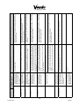
Test/Config Mode command
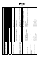
PDC will automatically ignore the inappropriate command.
received while not in Test/
Config Mode.
Ex. Test Motors command
received while the machine is
vending.
Inappropriate Command
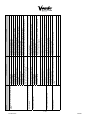
Run Discovery 2. If no changes were made to the trays/shelves in SXY,
may indicate a missing reflector.
Machine will automatically perform Discovery 2.
Discovery 1 scanned the
latch side of the SXY and
the shelves discovered do
not match those stored in
FLASH.
Shelf configuration changed.
Failed Conformation
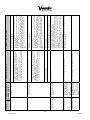
1) (In factory), if never able to program FLASH, the FLASH may be
misconfigured (Fujitsu chip has Sector 7 protect on)
2) Random Failure: Cold reboot SXY and try again.
3) FLASH chip has failed or worn out (after many thousands of uses). Replace FLASH chip with new. The FLASH chip holds the software, so
it is the PDC software chip. Don’t forget to save relevant parts of PDC’s
configuration.
4) If FLASH chip change does not work (try more than once, using
care to install chip without damage), there may be a failure in the PDC
circuitry. Replace PDC board.
Reboot the machine.
Reboot the machine.
If problem exists, change the PDC and VMC software.
Unplug machine. Replace any malfunctioning motors or sensors. Plug
the machine back in.
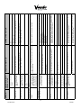
If Green or Orange heartbeat, check MDB communication cable
connections as above.
If Red heartbeat, PDC has logic error. Unplug machine, wait 5 seconds
and plug machine back in.
If no heartbeat, LED is off and Flo power indicator is off, the PDC
does not have power. Check the heartbeat on the VMC. If the VMC
is powered, check the MDB cables. If no heartbeat and the Flo power
indicator is on a problem with the software flash chip may be likely. Replace the flash chip. If this does not fix the problem, replace the
PDC.
Check LED’s on PDC. Lower right hand light should have
heartbeat. Green heartbeat = PDC not receiving communication
from VMC. Orange heartbeat = PDC both receiving and
transmitting communication.
Red heartbeat = PDC closed communication.
No heartbeat (LED off or solid color LED) = PDC not operating. If
no heartbeat, check Flo power indicator (should be solid green).
Run Vending motors in Test Motor. Check health of sensors in
Test Mode Check Sensors.
Unplug machine. Reset any loose pins in harnesses. Reseat reseat
harness plugs. Plug in machine.
Check all harnessing between PDC and VMC.
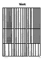
If Green or Orange heartbeat, check MDB communication cable
connections as above.
If Red heartbeat, PDC has logic error. Unplug machine, wait 5 seconds
and plug machine back in.
If no heartbeat, LED is off and Flo power indicator is off, the PDC
does not have power. Check the heartbeat on the VMC. If the VMC
is powered, check the MDB cables. If no heartbeat and the Flo power
indicator is on a problem with the software flash chip may be likely. Replace the flash chip. If this does not fix the problem, replace the
PDC.
Check LED’s on PDC. Lower right hand light should have
heartbeat. Green heartbeat = PDC not receiving communication
from VMC. Orange heartbeat = PDC both receiving and
transmitting communication.
Red heartbeat = PDC closed communication.
No heartbeat (LED off or solid color LED) = PDC not operating. If
no heartbeat, check FLO power indicator (should be solid green).
Changes to the configuration
could not be stored in PDC’s
FLASH chip.
An error occurred that did not
conform to any known error.
Failed Unknown
Unplug machine. Reset any loose pins in harnesses. Reseat reseat
harness plugs. Plug in machine.
CORRECTIVE ACTION
Check all harnessing between PDC and VMC.
CHECKING METHOD
Setup Flash Write Failed /
Setup Flash Write Failed
PDC failed to communicate
with VMC.
DESCRIPTION OF
ERROR CODE
Failed Communication
ERROR