1
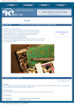
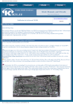
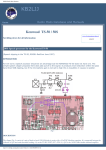
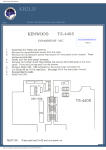
KB2LJJ Radio Mods Database
KB2LJJ
www.r6-ru4montesecchieta.it
IZ5CCV
Home
Radio Mods Database and Manuals
Modifications for the Kenwood TS-850
Expanded RF M/C
1 Disconnect the power and antenna.
2 Remove the 16 screws top and bottom covers from the radio. Be careful no to
break the speaker wires.
3 Remove the top and bottom screws from each side of the front panel assembly.
4 Pull the front panel forward to expose the DIGITAL Board.
5 Locate and cut the lead DIODE D11
6 Reassemble the radio.
7 Reset the microprocessor ( Holding the [ A=B] Key while turning the power ON.
Click to view picture
TS-850S observations
TS-850S All band transmit
TS-850S Broadcast Band Sensitivity
TS-850S Additional Front Panel Functions
Step by step instructions to disable the broadcast band attenuation for TS850S
TS-850? ACC-2 audio problem
Adjustable moni. on CW, TS-850S
TS-850 service manual, error corection
TS-850S and speaker/headph
TS-850 and Ten-Tec Titan 425 PA
http://www.kb2ljj.com/data/kenwood/ts-850.htm (1 di 31)01/09/2009 0.13.59
KB2LJJ Radio Mods Database
KAM-PLUS Problems!! with TS-450 & 850
TS-450,TS-850 feedback,ACC-2 Conn
Modification for External keying, while using the internal keyer
TS-850 Separate Receive Antenna Modification
TS-850 Separate RX antenna input mod
The switch box
Computer Interface for the TS-850, without using the IF-232 Level Converter
TS-850 Power Output Control
TS-850 Level Attenuator for DRU-2 playback audio
TS850 + Transverter oder Preselektor German language
TS-850S Distorted TX w/TNC connected
TS-850S Low/no Receive sensitivity
TS-850S No audio from VS-2
TS-850S Mixer FET change
TS-850S "Click noise" with NOTCH ON
Full transmit for the UK version of TS-850S
TS-850 2nd RX output mod
A Band Decoder for the Kenwood TS-850 HF-Transceiver
TS850s alc problem
Noise Blanker Mod Kenwood TS-850
TS-850S observations
Observations of KC2CT
Having lived with Kenwood's TS-850S tranceiver for 5 days, here are some of my observations:
●
●
●
●
While the manual shows 35 power-on front panel adjustments, there really are 36. Function number 35 is set from
the factory to the OFF state. Well, what exactly is this unknown function? Well Bunkies, this enables the tranceiver
to transmit on 27.500 through 28.000 mhz! Do yourself a favor, and set this option to ON for TX inhibit! DO NOT
JEAPORDIZE YOUR LICENSE! Why in the world did the factory allow this??? Maybe they don't want the
Chicken Banders butchering up the rigs....
Tone control. The setup only allows Burst or Continuous modes, there is no way to turn it OFF, even though the
manual indicates there is a way.
Quick memory function. You MUST pass through either the VFO A or VFO B registers to program these.. You
cannot go from standard memory to quick memory directly.
My 850S came out of the box running low power (50 - 75w PEP), so I called the local ham radio dealer inquiring
about service manual availability. Well they had them in stock, but at a price of $50.00! Unbelievable! Kenwood
wants fifty dollars for (in the continuing Kenwood tradition) a terribly organized, incomplete, and horrible reading
manual!!! Well, I dug into the schematics and opened up the the radio, here's a list of items that might be of interest
to some:
RF Board Controls
http://www.kb2ljj.com/data/kenwood/ts-850.htm (2 di 31)01/09/2009 0.13.59
KB2LJJ Radio Mods Database
----------------VR - RX BAL
VR - TX BIAS
VR - TX BAL
VR - TYP (50W output power adjust, used with S1 below)
VR - MIN (?????) / internal antenna tuner
VR - TUN (Tune mode power adjust)
VR - VSF (THIS IS THE 100W POWER OUTPUT CONTROL)
VR - SWR Protect activation
VR - PWM (Forward power meter calibration)
VR1 - RWM (Reflected power meter calibration)
VR1 - AL0 (ALC meter zero)
VR1 - ALM (ALC meter calibration)
VR1 - CPM (Processor meter calibration)
VR1 - ALG (ALC gain adjustment)
S
- All Band Power Down Switch (Decreases power to 50 watts)
IF Board Controls
----------------VR
VR
VR
VR
- Beep volume
VR
- Sidetone volume
VR
- Processor adjust
VR
- ?????
VR8 & VR9 - ?????
VR1
- ?????
VR1
VR12 & VR13 - S Meter adjust
VR14 & VR15 - AGC adjust
VR1
- Notch filter adjust
●
●
●
●
●
●
●
●
●
PLEASE NOTE!
Most of these controls are 1/8" pots, so if you intend to adjust them use a VERY SMALL non-metallic tool.
My 850S also came out of the box with the RIT/XIT control not dis- playing 0.00 khz at fiducial (12 o'clock
position) center. Behind the front panel in the upper right corner is the control for center adjust. It just needed a wee
bit of tweaking... Along with this control on the circuit board are the master adjust- ments for the SSB slope tuning
(High Cut and Low Cut).
When both top and bottom covers are removed, on the left-hand side is the FM board. There are 3 (three) pots on the
board. They are FM Wide (12khz) deviation, FM Narrow (6khz) deviation, and FM Mic gain.
FM mode defaults to WIDE (12khz). This is WAY too wide for accessing any 10m repeater. Hit the 455khz filter
button again for FM-N (narrow). This will set the IF to 6khz width, and you be able to work FM 10m stations. Note:
The 8.83 filters are NOT selectable in FM mode.
Memory scrolling via M CH./VFO CH. You can bypass all unused channels if you press the 1 mhz button. With the
button active, only stored memory channels will be displayed as the knob is rotated.
Tunable memories. Out of the box, the radio is set up for non- tunable memories. Just bring up setup function xx on
the display, and set it to ON, and ALL memories can be tuned via the VFO. When use the M.CH/VFO CH. switch
you will be returned to the original frequency & mode setting in the memory.
It may or may not be obvious to some, but the radio is capable of cross-band and/or cross-mode operation. Just
pump the required modes and frequencies into memory channels or VFOs, and you're off and running. Hope you
have a very broad banded antenna!
CW message storage is lost when you power off the radio. I didn't order the DRU-2 option (yet), so I don't know
whether these messages will be saved. You'd think that with everything else that is stored in RAM and backed up by
battery, that Kenwood would have made pro- visions to keep recorded messages alive also. A modification????
When adding additional filters, is is necessary to set the corresponding switch on. Under the hatch on top, is a 4
position dip switch. The manual shows a picture of it, but makes no mention of their settings. This switch is
necessary to inform the micro- processor of the filters' absence or presence. ON is for presence, OFF is for absence.
http://www.kb2ljj.com/data/kenwood/ts-850.htm (3 di 31)01/09/2009 0.13.59
KB2LJJ Radio Mods Database
Below is the switch diagram:
----| = |
| = |
| = |
| = |
----O
O
N
F
F
●
●
●
<-<-<-<--
YK-88C-1, YK-88CN-1, YK-88SN-1
YK-88CN-1, YK-88CN-1, YK-88SN-1
No Function
YG-455C-1 or YG-455CN-1
I received the DRU-2, voice recording unit this week, and installed it. Here's what I found:
The unit comes with a lithium battery for backing up the voice messages when the rig is powered off.
The initial state of the DRU-2 is:
Message 1 - 8 seconds
Message 2 - 8 seconds
Message 3 - 16 seconds
●
●
●
●
●
●
●
You can halve the sampling rate via front panel setup control xx. This will effectively DOUBLE the time of of each
message, however, the quality of voice repro- duction will suffer because of the lower sampling rate.
On playback of the messages, the microphone IS NOT disabled, so be quiet when you're transmitting stored
messages.
Use the MONI function to hear what you've recorded and/or are transmitting, and tèe MIC gain control to keep the
ALC in range, as the DRU-2 drives the radio much harder than the microphone input.
The high boost function and speech processor are available to the DRU-2 during transmit.
I also got the VS-2 voice unit. The voice is the same as the older VS-1 for the TS-440, and TS-940, but the unit is in
a smaller package. It will speak the frequency in either English or Jápanese. There is a volume control pot on the
bottom of the board whécè should be adjusted PRIOR to screwing down the VS-2. The output on my unit was very
low, until I tweaked it up. Also there are jumpers on the board to speed up the voice playback... You'll need to
consult the instruction page for the VS-1 for speeds, as there is nothing mentioned in the instructions for the VS-2.
A note on output power of the rig. The radio uses 2SC2789's... These devices are rated as 100 watt devices
Kenwood is running the finals VERY conservatively. When playing around with output, I had the rig dead-keying
175 watts, but backed it down to 100 watts, as I didn't want to blow up the rig, but I was äefinitely smiling as the
Birds' meter swung with a 250 watt slug!
The ROM chip on the digital board is socket. Kenwood had problems witè early 440's and 940's with poor soldered
connections. While it's a nice idea to allow removal and replacement of the ROM to add features/fix bugs, this
might become a problem area in the future.
Hidden function!!! If you turn on the radio while holding down the VOICE button, EVERY button on the radio will
acknowledge its function via morse code! This is a terrific feature for sightless hams! I can't understand why it is not
mentioned in the owners manual or marketing literature!
TS-850S All band transmit
http://www.kb2ljj.com/data/kenwood/ts-850.htm (4 di 31)01/09/2009 0.13.59
KB2LJJ Radio Mods Database
Kenwood markets this radio worldwide, and has made orovisions to allow the radio to transmit between 1.625 mhz
and 29.999 mhz.
I am providing this modification for INFORMATIONAL PURPOSES ONLY! DO NOT TRANSMIT OUT OF
BAND, THIS WILL JEAPORDIZE YOUR LICENSE, AND HAVE THE FCC, AND/OR INTERNATIONÁL
AUTHORITIES KNOCKING AT YOUR DOOR!!!
The All-band transmit modificatéon requires the removal and re- location of a diode on the the digital board which is
located behind the front panel. The US version of the radio has diode D11 installed, and diode D9 removed. D11 must
be removed, and installed in the D9 position. This modification IS NOT for the faint of heart, as it entails removing
the front panel, and the digital board. Note that the digitál board has solder holes thát are through-soldered; that is,
there are circuit traces on both sides of the board, so make sure that ALL solder is removed from the holes. This
modification will also allow the antenna tuner to tune anywhere the receiver is tuned. This modification should ONLY
be performed ây those familiar with soldering and de-soldering techniques, and requires patience, and dexterity.
Thanks to Bill K0ZL for this picture.
ser comment
Subject: Diode not needed in D position
http://www.kb2ljj.com/data/kenwood/ts-850.htm (5 di 31)01/09/2009 0.13.59
From: Max VE3TMT
KB2LJJ Radio Mods Database
On some TS850's it is not necessary to install a diode in the D9 spot. Clip D11 (the one on the right end) and check for
proper results first. On my TS850 it worked without putting a diode in D9.
From: Jaye
User comment
Subject: Full TX on the Kenwood TS-850s
I have recently preform the modifcation on the TS-850s for full TX, i have to coment that i did'nt have any dramas with
this procedure,But!where it explanes to remove the diode D-11 then replace in the D-9 postion this is not nessary, just
clip D-11 and you will also have remove diode D-12 that is in parallel series on the back of the digital board, this requires
removing the hole digital board to gain access to Diode D-12, also will coment that the board is not easly removed, due to
the funny looking screws which kenwood have placed on the board(you will need a special tool or some smart thinking)
in regards to the D-9 diode??? no go on this rig! and yes it wasn't to hard! ,actually had 3 stubbies of VB (Beer)then i was
back on the air, best of luck Jaye,your Mate Down Under. :-))
TS-850S Broadcast Band Sensitivity
BCB sensitivity REALLY suffers as a 24db attenuator is inserted when band-switched. This attenuator circuit is very
similiar to the TS-430/440. Possible modification?
TS-850S Additional Front Panel Functions
Pressing SCAN + TX-M.CH will set the radio into its extended function mode. These options can be scrolled via the M.CH/
VFO CH. switch. The following are the extended functions:
00 - This is the ROM Cèecksum displayed as a 4-digit hexadecimal
number This cannot be changed.
01 - Allow filter selection in transmit. Initially set OFF.
02 - Antenna tuner power down.
Initially set to OFF.
03 - Antenna tuner non-stop mode. When set to on, the antenna
tuner will not stop when the lowest VSWR is found. Initially
set to OFF.
04 - Store mode, and filter settings prior to changing bands, or
cèannels. Initially set to ON.
05 - Display -HELLO- on digitial display, anä send it in Morse
code on power up. Initially set OFF.
06 - Turn full LCD display ON on power on.
http://www.kb2ljj.com/data/kenwood/ts-850.htm (6 di 31)01/09/2009 0.13.59
Initially set OFF.
KB2LJJ Radio Mods Database
07 - Turn Subtone ON or OFF. Initiálly set ON. Note tèat even
when set off, the TONE indicator will be lit on the display.
08 - Unknown. Initially set OFF.
Step by step instructions to disable the broadcast band attenuation for TS-850S
This mod greatly improves the sensitivity and likewise the reception on the AM broadcast band.
No noticable unwanted side effects have occured following this procedure.
I live within three miles of a 5,000 watt broadcast station on 1150 kc's and am able to listen to stations on either side of that
station. There is some splatter but using the notch filter and the attenuation on the front of the radio takes care of that for
the most part. This is *NOT* complicated and can be done in fifteen minutes. Only one caution here:
you WILL BE SOLDERING TWO POINTS ON A CIRCUIT BOARD THAT IS LOADED WITH SURFACE
MOUNTED COMPONENTS!!! There is little room to work on the board, so be very careful with your iron! If you don't
feel comfortable soldering, get someone else to do it as you can cause a solder bridge and ruin your radio without even
trying. With that in mind, here goes:
1. remove the eleven screws that secure the bottom cover to the rig. the six ones on the sides and the five on the bottom
cover itself.
2. remove the bottom cover. there are no wires attached to the cover. lift it right off. leave the top cover of the radio
ON.
3. locate the RF BOARD. it's number is: X44-3120-00. this is the board where you plug the optional filters into. with
the open radio in front of you, and the front of the radio facing you, the RF BOARD is the one on the left. (there are
only two boards under the bottom cover)
4. locate the chrome like shield on the rear of the RF BOARD. it's made out of shiney steel. remove the four screws
that hold this shield to the board.
5. remove the shield by lifting the front of it up while sliding it forwards, towards you. watch out for all the little wires
and ribbon cables going to and from the RF BOARD.
6. look at the rear of the board and towards the left corner.(the radio is stil facing you upside down) notice two I/C's
numbered IC1 and IC2. directly behind the I/C's are a bank of adjustable coils in metal cans. there are nine of these
coils in a group. directly to the left of these coils are many green and red inductors which are standing up. they look
like resistors but they're really small coils.
7. these inductors are part of the bandpass filtering for each of the bands on the radio. the capacitors and resistors that
complete the bandpass filtering are on the other side of the board and are of the surface mount type. you are only
concerned with the bandpass filter for the .5 to 1.6 band. notice the numbers for the inductors. find L8 and L9. they
are right at the edge of the board in the left rear corner you will notice that .5 - 1.6 is stamped right next to L9.
BINGO! you have found the part of the circuit that you will modify.
8. look at where the .5 - 1.6 is stamped on the board next to L9. you will see two bronze or gold solder points there
directly next to the numbers .5 - 1.6 . there is nothing soldered at those two points. this is where you will solder a
jumper wire between the bronze points. do NOT confuse it with the other two solder points with the line running in
between them next to the phillips head screw!!! you want the two points that are spaced very close together that is
right next to L9.
9. you will have to do the soldering on the OTHER SIDE OF THE BOARD. remove the nine phillips head screws that
hold the RF BOARD to the chasis.
10. on the back of the radio, look for the switch stamped SW 1. it's right below the grounding post and has the two
postions: INT and EXT. remove the two screws that hold the switch to the back of the rig. the switch is soldered to
the RF BOARD and you wont be able to lift the board up until the screws are removed.
11. unplug enough cables from the board so you'll have enough room to lift the RF BOARD up to solder the jumper.
there is no need to remove the board from the rig. slide it towards the front of the rig until the switch SW 1 clears
the back of the rig and lift the left side of the board up and prop it up with a small block of wood.
12. locate the bronze solder points on the underside of the board. there will be a small amount of solder at these two
points on the underside of the board.
http://www.kb2ljj.com/data/kenwood/ts-850.htm (7 di 31)01/09/2009 0.13.59
KB2LJJ Radio Mods Database
13. bend a small jumper out of wire that fits the two bronze points on top of the RF BOARD. you will place the jumper
on the top and solder on the underside of the board. with a pair of needle nosed pliers, place the jumper into the
holes and simply heat up the existing solder on the underside until the jumper slips down farther into the holes.
you'll notice the large amount of components on the underside versus the lack of components on the top of the
board. be carefull when heating the solder on the two points. you don'y want to disturb the surface mounted parts or
cause any excess solder to run onto them or the foil nearby.
14. you are now done. re-assemble in reverse order, plugging the wires back in carefully, making sure they don't get
plugged into the wrong place. also, avoid pinching them when replacing covers.
____________________________________________________________________
l
l
l
l
l X
__________________
l
l 4
L8
l
l
l
l 4
O O O O O O l
COIL BANK
l
l
l
O O O O O O l
l
l
l 3
.5 o
inductors l_________________l
l
l 1
O O O O O O
l
l 2
1.6 o
_______
_______
l
l 0
l ic1 l l ic2 l
l
l
l
-------- -------l
l 0
solder
l
l 0
point
l
l
l
l
RF BOARD
l
l
solder
l
l
point
l
l
l
l
l
l
L9
l
l
l
l
l
l
this area for optional
l
l
plug in filters
l
l
l
l
l
l
l
l
l
l
l
l___________________________________________________________________l
FRONT OF RADIO
Sorry, that's the best art work I can do. The purpose of the jumper is to bypass the two 150 ohm resistors that are in series
after the band pass filter. The resistors add between 20 and 25 db attenuation to the AM broadcast band. For some reason,
Kenwood thinks that the receiver would become overloaded by strong nearby broadcasting stations, which would cause
distortion. I simply don't find that to be the case. It's funny, Kenwood already had those two points there on the board, but
without the jumper......it seems to me that they had anticipated the need to bypass the attenuation in Europe or Asia. Thus,
all export models going to the states were missing that jumper. Who knows? I can't find any other reason for the jumper
points to be there.
Anyway, you'll notice an immediate increase of signal strength. You'll hear stations that you never knew were there! As I
said, if you are bothered by strong stations in your area, try using the 6 and/or 12db attenuation buttons on the front of the
rig.
http://www.kb2ljj.com/data/kenwood/ts-850.htm (8 di 31)01/09/2009 0.13.59
KB2LJJ Radio Mods Database
TS-850? ACC-2 audio problem
Following bulletin was sent to me by Dick, KB8DB:
KENWOOD/KAM SSB AUDIO PROBLEM
The problem is that some kenwood radios are being shipped with the rear panel audio output very sensitive. We
(kantronics) have had others report the same problem, and the following response was prepared by our service department:
Some adjustments in the radio and in the kam may be necessary when using these connections. SOLUTION:
Decrease the gain in the kenwood radio rear panel audio input circuit (may be labeled vr18, check your radio manual).
Increase the afsk output from the kam (remove jumper k5 for maximum output).
Set the kam to transmit in rtty mode, and radio in ssb mode, adjust vr18 (or gain control in radio that controls rear panel
audio input) for the radio manufacturer's recommended output when using rtty.
Now, when using the front panel microphone, low-level noise on the rear panel input will not be picked up or added to
microphone audio. (unquote)
73 from Stan G4KSJ @ GB7BEN.#43.GBR.EU
Adjustable moni. on CW, TS-850S
Hello everybody!
If you'd like to be able to adjust the volume with your "MONI-knob" on the frontpanel of your TS-850S when monitoring
your transmission on CW read this! Originally it's a fixed level controlled by VR5 internally.
This could be usefull when switching between the loudspeaker and the headphones.
When you're monitoring your CW with headphones at a pleasent level, and then disconnect the headphones and monitoring
with the loudspeaker the audio is quite low.
(IF-UNIT)
●
●
●
●
Remove the IF-UNIT (you must solder on the rear side of the IF-UNIT). Be careful to mark all the cables before
you remove them!!!
Remove R239 (330 kohm, close to VR5).
Install a new resistor (330 kohm) from the output of VR5 to the junction R229, R230, R231 and C172 (rear side of
the IF-UNIT, close to IC7).
Adjust VR5 to maximum audio level.
Now you're able to adjust your audio level in the CW mode with the "MONI-knob" at the front panel of your transeiver.
Gif file of the circuit board layout (445 Kb) where the mod is to be done in the radio.
73 de Nate Bargmann
Packet: KA0RNY @ WF0A.#SCKS.KS.USA.NOAM
E-mail: [email protected]
Valley Center, Kansas USA EM17hs
Visit my Linux + Ham Radio pages homepage.netspaceonline.com/~ka0rny/
http://www.kb2ljj.com/data/kenwood/ts-850.htm (9 di 31)01/09/2009 0.13.59
KB2LJJ Radio Mods Database
TS-850 service manual, error corection
Page 20:
2 Full break-in operation timing
-------------------------------...signal enters pin 10 of the BW-SW module from the...
should be
...signal enters pin 10 of the BK-IN module from the...
Page 21:
Resistor R3 (10 kohm) in the BK-SW schematic does not exist.
(This is corrected in the schematic that's in the user's manual)
Page 23:
Key up
-----In line 8 and 10 capacitor C230 is mentioned
-should be C231
TS-850S and speaker/headph
This is a very simple modification on the TS-850S to be able to hear the receiving station through the loudspeaker and the
headphones at the same time.
On ICOM rigs it does not require any modification at all as this is a feature built-in from the factory.
On ICOM rigs if you push the connector halfway into the headphone jack you have the sound in both the loudspeaker and
the headphones, then if you push the plug the whole way in, the sound is only in the headphones.
Unfortunally this is not the case on the TS-850S.
The headphone jack is a little different made on Kenwood rigs, so this modification does not allow you this "halfway"
feature described above. But still you are able to have the sound coming from the loudspeaker and the headphones at the
same time.
Modification.
Note!
This modification works on both mono and stereo headphones.
1. Remove all knobs at the front of the radio.
http://www.kb2ljj.com/data/kenwood/ts-850.htm (10 di 31)01/09/2009 0.13.59
KB2LJJ Radio Mods Database
2. Remove the front.
3. Remove the very small unit (E/6 page 57) that contains the phone jack itself.
4. Install a jumper between pin no. 1 and pin no. 2 on the CN8 connector.
TS-850 and Ten-Tec Titan 425 PA
If you're using the Kenwood TS-850S with the Ten-Tec Titan 425 linear PA read this!
This explains how to modify the TS-850S' full QSK feature and avoiding "hot switching" the relay in the amplifier when
operating full QSK.
As you probably know the correct way to prevent "hot switching" is to feed a signal to the Titan's "key-in" connector when
you transmit. When the linear's vacuum-relay is settled the Titan's "key-out" connector return that information to the
transceiver which then feed its output RF to the linear.
What's important here is that the transceiver DOES NOT feed any RF BEFORE the vacuum-relay in the linear is settled!
(If you do, you have the problem called "hot switching")
This is how to overcome the "hot switching" problem:
Open the TS-850 and do the following:
1. Remove the original TRX-relay (K3 at the RF unit).
2. Remove the IF unit.
3. Locate the BK-SW unit (X59-3880-00).
Cut between Q2's collector and pin 10 on the BK-SW unit.
Feed Q2's collector to the "key-in" on the Titan linear.
Feed pin 10 (where you cut) on the BK-SW unit to the "key-out" on the Titan linear.
4. Reinstall the IF-unit.
That's all!
I connected the collector of Q2 to pin #4 on the REMOTE connector and pin #10 on the BK-SW unit to pin #2 on the
REMOTE connector at the rear of the transceiver where you originally connect the keying of an amplifier.
That's why you should remove the TRX-relay (K3) as described in point no. 1.
Pin 4 on the remote connector should now be connected to the "key-in" on the Titan amplifier
Pin 2 on the remote connector should now be connected to the "key-out" on the Titan linear.
ONLY use shielded cables!!!
This modification works fine on my TS-850. I am able to operate full QSK at the maximum speed on the built-in keyer unit
without risking any damage to the vacuum-relay in the Titan at full output power (1600W).
http://www.kb2ljj.com/data/kenwood/ts-850.htm (11 di 31)01/09/2009 0.13.59
KB2LJJ Radio Mods Database
KAM-PLUS Problems!! with TS-450 & 850
Hello All,,
A common problem when using a KAM-Plus multimode with the Kenwood TS-850 or TS-450 occurs when the KAM-Plus
is coupled to the Accessory-2 socket on the back of the transceiver, producing noticable distortion of the transmitted audio
when using the microphone in SSB mode..
The problem is easy to cure by disconnecting the Accessory-2 plug from the back of the tranceiver, but this meant moving
the transceiver around every time one wished to operate on SSB..
The problem is caused by the input sensitivity of the rear Accessory-2 socket being set to high, so that it picks up very low
level noise from the KAM-Plus and associated computer wiring, this mixes with the microphone signal, to produce the
distortion.
The cure is to reduce the input sensitivity of the radio, thus reducing the chance of distortion, also it goes without saying
that the output from the KAM-Plus must be increased to compensate for this.
With both the TS-450 and TS-850, adjusting the input sensitivity is straight forward and the transceiver manuals show you
the appropriate control and its location.. This is in both cases VR18 to be found on the main board of the radio,(refer to
manual) in practice I found that it was best to adjust this control fully counterclockwise..
Then we need to adjust the output from the KAM-Plus by varying potentiometer R28 and setting removable link (K9), this
link is factory set on one post only, (in the open position)!! this should be connected shorting the two posts, thus putting the
KAM-Plus into the high output position, and then potentiometer R-28 is adjusted to give full power out from your HF radio
with very little ALC deflection, when the MIC gain is in the normal operating position..
Then I am sure you will find that your problem is over, you can now simply change from digital modes to SSB.. Remember
if you have your Beacon activated to turn it OFF or it could cause a few comments when operating SSB..
TS-450,TS-850 feedback,ACC-2 Conn
Hi if you are using the ACC-2 connector to interface with your multi-mode controller, you may have had a problem with
your transmitted audio signal being distorted, to eliminate this see bellow.
1. Set your meter on the radio to read ALC
2. PK232 OWNERS: if alsso using a VHF tranceiver, adjust the AFSK level for proper VHF operation as expalained
in chapter 3 of the operating manual.If not adjust for proper SSB operation.
DSP - 1232 / DSP - 2232 Owners: Adjust the appropriate AFSK level control for proper SSB operation as expalined
in chapter 3 of the operating manual.
3. Place the TNC in calibrate mode and press K to key the radio.
4. Adjust VR-13 on the TS-450 or VR-18 on the TS-850 so that the meter "Just comes off the peg" as described in the
section titled "SSB Tranciever Final Adjustments" (in the TNC operating manual).
5. Press Q to quit the CALIBRATE mode
This modification should not affect any of the other normal operations of the radio..
Copy of service bulletin from AEA
http://www.kb2ljj.com/data/kenwood/ts-850.htm (12 di 31)01/09/2009 0.13.59
KB2LJJ Radio Mods Database
Modification for External keying, while using the internal keyer
Author: N7EX (ex-N0DH), Dave Henderson
One of the minor draw backs to the TS-850 as a CW contest machine is the inability to use the internal keyer in conjunction
with an external keying circuit such as a personal computer or auxiliary memory keyer. As designed you must manually
throw a switch from internal to external keying to switch between one or the other. To make matters even more
inconvenient this switch is on the back of the unit and is not readily accessible during normal operation.
Simply said this modification involves running a new keying line from the junction of S1 and D51 on the IF Board. For
convenience this additional keying line can be wired to the DSP1 and/or DSP2 RCA phono jacks if you do not use the
external DSP unit.
The modification to the unit to resolve this problem takes less than 30 minutes to accomplish and can be done without
"permanently" modifying the unit which would detract from its future resale value. If you don't use the external DSP unit
then the two RCA phono jacks marked DSP1 and DSP2 can be used as additional keying input jacks as will be outlined
below. If you use the external DSP unit then the modification can still be accomplished by running the external keying line
out on a "pigtail." I highly recommend the purchase of a service manual which will greatly improve your ability to
indentify the circuit points involved in the modification.
Considering that the radio costs $1500 what's another $30 to keep from messing it up! By the way compared to the two TS930's that I nursed through the 80's, this radio is a breeze to trouble shoot and repair which I have had to do twice through
no fault of Kenwood (long stupid story ~8>).
From here you proceed at your own risk, if you fry the radio DON'T CALL ME. A precision low wattage solder pencil for
doing surface mount soldering is recommended, If all you have is a 150 watt Weller solder gun then read no farther your
better off taking the unit to an expert rather than "melt" the circuit traces.
I assume no risk for the accuracy or completeness of the enclosed information. All yee who enter here embrace all hope for
you may likely have a better contest radio when you are done.
1. Turn the unit upside down with the back of the TS-850 toward you.
2. Remove the bottom cover.
3. In this position the IF board is on your left.
4. Remove all the screws holding the IF board to the chassis.
(put them in a jar or something for safe keeping).
5. Unplug enough of the cabling to allow you to tilt the board up so that you can access the bottom side of the board
underneath S1 the "External/Internal" keying switch.
6. On the bottom side of the board directly underneath S1 you will see 6 solder pads arranged in two rows of three
pads each.
7. The middle pad on S1 nearest the back of the radio should be GROUND, solder the braid of an approximately 9
inch piece of small audio style shielded cable to this point, being careful to dress the coax so as not to short to other
circuitry.
http://www.kb2ljj.com/data/kenwood/ts-850.htm (13 di 31)01/09/2009 0.13.59
KB2LJJ Radio Mods Database
8. The middle pad on S1 in the next row up of three pads is the keying line. Solder the center of the shielded cable to
this point.
9. Route the other end of the shielded audio cable through the chassis in the vicinity of the DSP jacks above.
10. Carefully inspect all solder joints for shorts, etc. Replug the wire harnesses unplugged in step 5 above and
reassemble the board to housing. Reassemble the bottom cover.
11. Turn the unit over and remove the top cover.
12. Find the DSP input board with the three RCA phono jacks on it at the rear of the unit.
The two DSP jacks are on the right when facing the rear of the unit. There are two connectors on this board (a 2pin
and a 4pin). Unplug the 4 pin connector. Obtain another 4 pin connector and connect as follows (or directly solder to
the underside of the board as follows) If you only need one additional CW jack then ground is pin 2 (closer to center
of the radio)connect the braid of your new key line to this pin. The input from the middle RCA phono plug is pin 1
connect the ceneter conductor to this pin. Like wise if you want two additional CW jacks then do as above plus add
a short between pins 1 and 3. If you want a small RF choke or some ferrite beads on the center conductor of the
audio cable may prevent keying problems in high RF field environments...
13. Close the unit up and switch S1 to INTERNAL keying. You should now be able to key the unit via the internal
keyer (Via the standard key input jack) or with an external keyer or computer via the old DSP jacks, without having
to switch S1.
TS-850 Separate Receive Antenna Modification
Author: Brian, WA3WJD
Make a short loop of white telfon cable with a male and female BNC connector.
Loop it out of the back of the rig so just enough of the coax sticks out so the BNCs can be joined with a barrel connector.
Locate the little header connector on the filter board in the TS-850 that is on the receiver side of the TS850 antenna relay.
Pull that connector loose.
Spend a little time tracking down male and female header connectors that match what Kenwood uses. Install those on the
ends of the white teflon coaxes sticking in the back of the radio.
For normal use, just connect the BNCs with a barrel connector and the rig is normal. For Beverage use, connect an extra
antenna switch common and ant #1 to the BNC connectors, and put ur Beverages on the other positions.
http://www.kb2ljj.com/data/kenwood/ts-850.htm (14 di 31)01/09/2009 0.13.59
KB2LJJ Radio Mods Database
TS-850 Separate RX antenna input mod
Author: N6TR - [email protected]
This is near the top of everyone's list when they are asked "What things bug you about the TS-850S." I initially overcame
this deficiency by modifying my amplifier so I could connect a different receive antenna to the TR relay. However, I
wanted to change things so there wasn't as much RF getting into the RX antenna due to close proximity to the amplifier's
output. This became a problem when using the same receive antenna on a second radio (you knew two radio contest
operating was going to work its way in here somehow).
Ville, OH2MM had provided me with instruction on how he modified his TS-850S to have a separate RX input and this
inspired me to try it.
Here are some simple steps to hopefully inspire others:
It took me an unrushed two hours to do all this.
1. Remove the top panel (you don't need to take off the bottom one).
2. Remove the plate which sits between the fan and the back of the radio. This covers the output filter PC board.
3. Unsolder the connections to the SO-239 output connector.
4. Remove the three cables from the PC board next to the SO-239. This includes two coax and one 3 conductor harness.
5. Remove the two screws holding in the PC board and remove it.
6. Locate the trace that goes from the relay's normally closed contact. You can use an ohm-meter to find it - probe
from the wire that went to the SO-239. You will find a short trace on the back of the board which runs to a chip
capacitor. Cut this trace and solder some very small coax to each side of the cut - connect ground to the nearby
ground trace.
Make the cables about 4 inches long.
7. Remove the antenna tuner. There are 2 screws in the back and front (you will need a magnetic screw-driver) and one
on the side. You will need to carefully unplug two wire harnesses and one coax connector.
8. Drill two holes for phono jacks on the back of the radio. Be careful not to obstruct the screw hole for one of the
screws in the back of the antenna tuner. The best place is between the RF output connector and the groundpost. Put
them on top of each other and as close to the bump on the back panel as possible. I used a vacuum cleaner while
drilling to make sure no metal chips went anywhere.
9. You will find a small hole under the SO-239 where you can feed the two coaxs through. Solder them to the phono
jacks and reassemble everything. I put back to back diodes on the RX antennas input, but you may not want to do
this. A better thing would be to add a relay to disconnect the RX antenna input when transmitting. I took care of that
in project #2.
10. Obviously, you will need a jumper cable to make your receiver work again.
http://www.kb2ljj.com/data/kenwood/ts-850.htm (15 di 31)01/09/2009 0.13.59
KB2LJJ Radio Mods Database
The switch box
Parts list:
●
●
●
●
●
●
4 position rotary switch
DPDT 12 VDC relay
1 K Ohm pot (optional)
12 phono jacks (or you can get by with 9)
mini box for above and knobs.
Clamp diode for relay coil if not included in relay
This box does two things: disconnects the receive antenna input when transmitting and allows selection of the transmitting
antenna or one of three RX antennas when receiving. The pot can be used for RF attenuation if your rig doesn't have one.
The relay gets controlled by the PTT output from your rig that normally would go to your amplifier. Then one set of the
contacts is used to key your amplifier. Don't forget to put a diode across the coil of your relay if there isn't one internally.
Otherwise, you will have undesired arcing across the contacts of the relay in your radio.
The other set of contacts disconnect the output of the rotary swtich when transmitting. The rotary switch selects either the
signal coming from the transmitting antenna (from the TR relay in your rig) or one of three receiving antennas. I use two
phono jacks per RX antenna so I can feed them to other boxes for other radios. I also use two jacks for +12 volts so I can
jumper power to another box.
You can build up one of these boxes in an hour or two. You can epoxy the relay to the mini box.
If you want the pot there to act as an attenuator, I just hook it up like you would a volume control: one end is ground, the
other end goes to the output of the rotary switch and the wiper goes to the output. Use shielded cable as much as possible to
avoid stray pickup.
Computer Interface for the TS-850, without using the IF-232 Level Converter
By N6TR and possibly others, with zener idea added by K6LL.
Note: This interface will work with "TR," contest logging software by N6TR.
Click here for links to TR and other contest logging software packages, including shareware.
Computer Interface:
DB9 PIN 3 (TXD)
(DB25 PIN 2)
470 ohms
----////------------ TS850 ACC 1 PIN 3 (RXD)
|
|
|
---- 5 VOLT ZENER DIODE
/
http://www.kb2ljj.com/data/kenwood/ts-850.htm (16 di 31)01/09/2009 0.13.59
KB2LJJ Radio Mods Database
/
DB9 PIN 5 (GND)
(DB25 PIN 7)
DB9 PIN 2 (RXD)
(DB25 PIN 3)
|
|
------------------------
TS850 ACC 1 PIN 1 (GND)
------------------------
TS850 ACC 1 PIN 2 (TXD)
----|
|
|
-----
TS850 ACC 1 PIN 4 (CTS)
TS850 ACC 1 PIN 5 (RTS)
TS-850 Level Attenuator for DRU-2 playback audio
Author: K6LL - [email protected]
1. Remove the little hatch on the top of the radio.
2. With the front of the radio facing you, find connector CN505. It is a five pin connector near the filter DIP switches.
The white wire on the leftmost terminal carries the DRU audio output.
3. Cut the white wire and insert a 100K ohm micromini pot, shunted with a 220 pf capacitor. Adjust the pot until DRU
playback level matches live microphone level.
Dave Hachadorian, K6LL
http://www.kb2ljj.com/data/kenwood/ts-850.htm (17 di 31)01/09/2009 0.13.59
KB2LJJ Radio Mods Database
TS850 + Transverter oder Preselektor
Author: Werner Maier, DL4NER - [email protected]
Wenn man von hinten auf den TS850 schaut, ist rechts eine
komplette Leiste mit Steckern (ACC, diverse Cinch (ALC etc..))
usw. Oben sind zwei Reihen und unten ist noch eine dritte Reihe.
(da ist auch die Cinch IF-Out dabei, die original (lt. Manual)
benutzt werden sollte. Mir persönlich hat das mit den 12 Volt
nicht gefallen; das Risiko für Transverter und Nachsetzer bei
Ausfall der 12 Volt war mir zu groß!
Genau dazwischen (oben 2 Reihen, unten 1 Reihe) ist rechts ein
Platz von ca. 2cm hoch, 8cm Breit und 3 cm tief. da passen die
benötigten 4 Cinchbuchsen (drvout, drv in, ant out, ant in)
problemlos hin.
Diese muß man für den normalen KW-Betrieb nur außen mit
Cinch-Cinch-Koaxkabeln brücken. Da es sich um Kurzwelle (d.
h. f < 30MHz) handelt, dürfte die auftretende Dämpfung
vernachlässigbar sein.
Zudem gibt es dort in den Gehäusseverstrebungen IDEAL Platz
zum Kabeldurchführen, als ob es von Kenwood dafür vorgesehen
wäre und aus Marketinggründen zugunsten des TS950 gestorben
wäre. So schauts jedenfalls für den Bastler aus. Oder der Platz
wurder einfach präventiv für Stecker freigehalten... wer weiß...?
Vorgehensweise:
1.
2.
3.
4.
5.
!!!!! OHNE GEWÄHR !!!!!
Boden und Deckel abnehmen.
von oben: Filterplatine (mitte) wegnehmen.
Gehäuserückseite abschrauben, PL-Buchse ablöten (evtl. sind hier mehr als zwei Hände hilfreich!)
Anzeichnen, bohren, auf genügend Abstand zwischen den Cinch-Buchsen und Gehäuseverstrebungen achten. (ca.
16 mm Lochabastand reicht, damit man sich die Finger nicht klemmt, beim Betrieb hinterher wie z.B. Stecker
ziehen...) Beschriften mit z.B. ANT out, IF in, DRV out, FINAL in (oder wie's beliebt).
http://www.kb2ljj.com/data/kenwood/ts-850.htm (18 di 31)01/09/2009 0.13.59
KB2LJJ Radio Mods Database
6. Kabel auftrennen: von der IF-Platine (wenn das Gerät
umgedreht wurde, vorne links) gehen ziemlich hinten an
den Steckverbindungen nach hinten mitte unten zwei
Kabel weg, CN1 und CN2 (weiss und Rot/Orange/
Rostbraun). Die beiden Kabel sind im Bild zusätzlich mit
einem gelben beschrifteten Klebeband gekennzeichnet.
7. Das eine führt direkt zur Antennenumschaltplatine, wo
auch die PL- Buchse angelötet ist. Auftrennen,
Verlängern und auf 2 der Cinchs legen. Das zweite führt
direkt zur Final-Unit (unter der Filterplatine). Auftrennen
und auf die Cinchs führen.
8. sind die Buchsen hinten RICHTIG beschriftet? und
RICHTIG verbunden? Besser mehrfach prüfen, das Teil ist teuer! Ist die Beschriftung eindeutig?
9. Zusammenbauen. Dabei ALLE Steckverbinder wieder stecken. Mögliche Fallstricke sind vielleicht:
● Verbindung Final-Unit-out -> Filter-Unit-in ? (muss gelöst werden, um die Filterunit auszubauen).
● PL-Buchse wieder angelötet ?
● Lautsprecher wieder angesteckt ?
10. Hinten brücken und als KW-TRX testen. Preselektor anstöpseln, testen. Transverter anstöpseln, testen.
11. !!!!! OHNE GEWAEHR !!!!!
Das Schöne ist nun, daß man problemlos einen Preselektor dazwischenschalten kann. Ebeneso problemlos geht das mit
Transverter- Betrieb, ohne Angst um Transverter und TRX haben zu müssen, falls mal die 12V Steuerspannung vom
Transverter ausfällt. (Lt. Aussagen eines Fachhändlers nimmt dabei nicht nur der Transverter sonder auch der TS-850
gewaltig Schaden.).
Und: Die Signale nach Außen unterscheiden sich von der Original-Kenwood- Schaltung (->Transverterbetrieb) nur
dadurch, dass jeweils ein Relais weniger in der Kette liegt.
Signal
orignial
modifiziert
Vorteil
Nachteil
10m-RX
direkt zur Antennenbuchse
wird nach
Antennenbuchse und RX/
TX- Relais
zugeführt.
Preselektor- Betrieb
möglich.
Ueberspannungsdiode wird umgangen.
(Gewitter im
Transverter? Dann ist
eh' alles zu spät!)
10m-DRV
wird vor CN1 mittels Relais
auf CN25 geschaltet und von
dort mittels im Gerät
umzusteckender Brücke auf
die IF-Out-Buchse gelegt, die
dann nicht mehr für ZF-Oszi
geeignet ist.
wird ohne Relais 1. Man muss nicht
nach CN1 direkt mehr mit 12 V
aufgetrennt.
schalten.
Rückbau: (für Verkauf, falls gewüscht):
Löcher:Kenwood-Aufkleber.
Durchtrennte
http://www.kb2ljj.com/data/kenwood/ts-850.htm (19 di 31)01/09/2009 0.13.59
2. Wenn die DRVLeitung aufgetrennt
ist, sendet die
Endstufe auch nicht.
Löcher in der hinteren
Abdeckung und ein
"verbasteltes" Gerät.
KB2LJJ Radio Mods Database
Leitungen: Ersetzen durch originale Leitungen (gibts bestimmt für Geld bei Kenwood).
73 de Werner Maier, DL4NER email: [email protected] Viel Spaß mit Preselektor oder Transwerter.
Zugriffe Seit 9/97:
TS-850S Distorted TX w/TNC connected
Author: Kenwood Communication, inc.
Service Bulletin no. 1000 (10 October 1992)
We have received several reports of distorted transmitter audio when using a TNC controller such as the AEA PK-232 or
Kantronic KAM, etc. The symptom will generally disappear if the transceiver and TNC units are powered from different
sources.
Cause:
The audio output level form the TNC is generally too high and causes overload of the microphone amplifier circuit. In
previous models such as the TS-440S the incoming TNC audio was inserted after the microphone amplifier. With the TS850S it is inserted before the microphone amplifier. Just moving the insertion point to the output of the circuit is
satisfactory since the drive level for FM packet is higher then that required for SSB.
Procedure:
1. Add a 10 dB attenuator to the PKD line on the IF unit (X48-3080-XX). This will prevent overmodulation of the
microphone input circuit.
a. Change chip resistor R258 from 2.2 Kohm to 1 Kohm (RK73FB2A102J)
b. Change chip resistor R260 from 220 to 330 ohms (RK73FB2A331J).
2. Add the following note to page 29 of the Instruction manual.
3. When adjusting for proper ALC levels with an AFSK RTTY terminal or Packet TNC terminal you should adjust VR18 on the IF Unit for a reading similar to the one shown in the accompanying diagram.
Note: The transceiver and RTTY or TNC terminal should use separate power supplies, in order to prevent RFI
(Radio Frequency Interference).
Caution: This modification requires soldering equipment rated for CMOS type circuits. It also requires familiarity with
surface mount soldering techniques. If you do not have the proper equipment or knowledge do not attempt this modification
yourself. Seek qualified assistance.
http://www.kb2ljj.com/data/kenwood/ts-850.htm (20 di 31)01/09/2009 0.13.59
KB2LJJ Radio Mods Database
Time required for this modification is ½ hour or less.
TS-850S Low/no Receive sensitivity
Author: Kenwood Communication, inc.
Service Bulletin no. 1006 (22 January 1993)
Symptom:
Reports of low or no receive sensitivity accompanied by a lack of audio from the speaker during CW or SSB modes might
be caused by improper RXB voltage levels. Normal RXB voltage is +8 Vdc during receive and 0 Vdc during transmit. If
you find approximately + 2 Vdc during receive you might suspect a problem with a leaking diode, D31 on the RF unit
(X44-3120-00).
Cause:
D31 is used as the transmit switching diode. Leakage of this diode id most probably caused by electrostatic surge or
discharges from the antenna.
Parts required:
D31, MI204
Procedure: A temporary cure for units that have already been manufactured is to replace D31 with an MI204 diode. Future
production radios will change D31 to an LFB01 diode and incorporate a change in the printed circuit foil pattern to allow
addition of a series diode. D103 (LFB01).
Caution: This modification requires soldering equipment rated for CMOS type circuits. It also requires familiarity with
surface mount soldering techniques. If you do not have the proper equipment or knowledge do not attempt this modification
yourself. Seek qualified assistance.
http://www.kb2ljj.com/data/kenwood/ts-850.htm (21 di 31)01/09/2009 0.13.59
KB2LJJ Radio Mods Database
Time required for this modification is 15 minutes or less.
TS-850S No audio from VS-2
Author: Kenwood Communication, inc.
Service Bulletin no. 1034 (6 December 1993)
Symptom:
Several have reported a problem with the Voice Synthesizer Unit VS-2 not voicing the frequency reliably when the Voice
button is depressed. This symptom is caused by a drop in the 5C voltage from 5 Vdc to approximately 4.5 Vdc when the
VS-2 is connected. The following change will correct this symptom.
Parts required:
Qty
1
Description
47 µH Chip coil
Old part No.
L40-221-48
New Part No
L40-4701-48
Circuit desc.
L501
Procedure:
Change L501 from 220 µH to 47 µH on the RF unit (X44-3120-00 C/4).
Caution: This modification requires soldering equipment rated for CMOS type circuits. It also requires familiarity with
surface mount soldering techniques. If you do not have the proper equipment or knowledge do not attempt this modification
yourself. Seek qualified assistance from your closest Kenwood Service Center (Long Beach, CA, or Virginia Beach, VA).
Time required for this modification is 30 minutes or less.
http://www.kb2ljj.com/data/kenwood/ts-850.htm (22 di 31)01/09/2009 0.13.59
KB2LJJ Radio Mods Database
TS-850S Mixer FET change
Author: Kenwood Communication, inc.
Service Bulletin no. 1046 (28 March 1994)
Symptom:
Several units were discovered during production by our QC department that experienced difficult when the transceiver was
being adjusted for an S-1 reading on the S-meter.
Countermeasure:
Variations in the gain of the devices used for Q16 and Q17, the second mixers, on the RF unit (X44-3120-00) appear to
cause of this symptom. We, therefore, recommend replacing these two transistors with 2SK520(K43) devices. These
devices have lower IDSS (Drain breakdown current), and therefore provide a greater conversion gain. As a result the total
gain of the circuit is increased.
Parts required:
Qty
2
Description
Second Mixer FET
Old part No.
2SK520(K44)
New Part No
2SK529(K43)
Circuit Description
Q16, Q17
Time required for this modification is 60 minutes or less.
TS-850S "Click noise" with NOTCH ON
Author: Kenwood Communication, inc
Service Bulletin no. 1049 (28 March 1994)
Symptom:
When a strong signal of S-9 or greater is received at the antenna terminal with the NOTCH circuit ON a "clicking" noise
might be noticed. This is caused by excessive response in the AGC loop circuit.
Countermeasure:
The changes detailed below will add additional delay to the AGC circuit and reduce or eliminate this tendency.
Parts required:
http://www.kb2ljj.com/data/kenwood/ts-850.htm (23 di 31)01/09/2009 0.13.59
KB2LJJ Radio Mods Database
Qty
1
1
Description
22 Kohm chip resistor
0.47 µF capacitor
Old part No.
RK73FB2A103J
NA
New Part No.
RK73FB2A223J
CQ92M1H474K
Circuit Description
R289
NA
Caution: This modification requires soldering equipment rated for CMOS type circuits. It also requires familiarity with
surface mount soldering techniques. If you do not have the proper equipment or knowledge do not attempt this modification
yourself. Seek qualified assistance from your closest Kenwood Service Center (Long Beach, CA, or Virginia Beach, VA).
Time required for this modification is 60 minutes or less.
Full transmit for the UK version of TS-850S
Author: Pred - [email protected]
This mod concerns only the UK kenwood TS-850S.
On the circuit board behind the front panel lies a bank of diodes numbered D1-D11 all diodes are there except for diode
D10 to unlock the uk TS-850s to full transmit.
Just cut or remove diode D11.
Perform full cpu reset, when powering unit after modification for full reset press and hold A=B while turning on unit ......
Pred
http://www.kb2ljj.com/data/kenwood/ts-850.htm (24 di 31)01/09/2009 0.13.59
KB2LJJ Radio Mods Database
TS-850 2nd RX output mod
Author: Gary G4iFB - [email protected]
The rules for RSGB National Field Day allowed the use of a second receiver but (at least in Restricted Section) just one
antenna. The second receiver could be used as a "spotter", for example to keep an ear on 28 MHz for sporadice openings,
or to check whether there is sufficient activity on another band to justify a band-change.
In the absence of a top-of-the-range transceiver with a second receiver built-in, I was prompted to make following
modification to my TS850 such that an external receiver could be connected to the single antenna, yet be disconnected
automatically when the TS850 transmits.
The modification is described in detail step-by-step below, but first you will need the following items:
●
●
a small length (about 20cm) of miniature coaxial cable, for example Maplin part number XR88V (note - the
characteristic impedance of miniature coax is typically 75 ohm giving a mis-match to the 50 ohm impedance of the
rig and antenna system, but such a small length of cable is required that there is no noticeable effect in practice)
a coaxial "line" socket e.g. SO239, BNC or Belling-Lee (again, the impedance mismatch caused by using 75 ohm
connectors has a negligible effect in practice);
●
a fine-tipped soldering iron and multicore electrical solder;
●
a medium (e.g. “number 2”) cross-head (Phillips) screwdriver.
NOTE: a modification such as this is liable to void the manufacturer's warranty - proceed at your own risk. It also involves
a fairly delicate soldering operation so DO NOT ATTEMPT THIS unless you are competent and confident at soldering.
1. Switch off the power and disconnect all external leads to the rig. Clear a space on the table in which to work.
2. Remove the rig's top cover:
a. Remove 11 cross-head screws (3 on each side, 2 front and rear on the top, and the last one centrally on the
top panel - don't remove the 4 screws holding the loudspeaker to the top panel!). Keep the screws safely in a
container to one side.
b. Carefully lift the top cover until you can reach the loudspeaker cable - remove this by pulling off the small
white plastic plug from the socket mounted on the printed circuit board under the loudspeaker.
3. It is probably easiest to turn the radio so the rear panel is towards you. Remove the metal lid from the TX output
bandpass filter unit in the middle at the rear of the TS850, with a black rubber section attached (which normally
insulates it mechanically from the top panel). There are 7 cross-head screws to remove.
4. Find the small printed circuit board immediately behind the rig's SO239 antenna connector. The black rectangular
relay on this board is the main TX/RX changeover relay. Remove this board from the radio:
a. Carefully disconnect the two coaxial cables by pulling out the miniature push fit plugs from the boardmounted sockets, and pull out the white plastic plug connecting the control wires to the board.
http://www.kb2ljj.com/data/kenwood/ts-850.htm (25 di 31)01/09/2009 0.13.59
KB2LJJ Radio Mods Database
b. Remove both mounting screws.
c. Unsolder the SO239 socket from the board - both inner and outer connectors need to be unsoldered - and lift
out the board.
5. This is the fiddliest part of the job - get help now if you are not confident at soldering. Solder your short piece of
miniature coax to the underside of the TX/RX relay board, in parallel with the TS850 receiver output connector
labeled "RAT CN6". The coax should preferably exit to the rear of the board so that it will pass directly through the
TS850 rear panel when reassembled. The coax centre conductor should be soldered to the "RAT CN6" pin nearest to
the small coil labeled "L13", and the braid to the adjacent (centre) "RAT CN6" pin which is earthed. Check
carefully that the joints are good (shiny and clean), and that no solder blobs or flakes remain on the board.
6. Pass the free end of the new piece of miniature coax out through the gauze on the rear panel of the TS850 - you may
need to enlarge a hole in the gauze slightly, but the coax should be a fairly tight fit.
7. Replace the TX/RX relay board in the radio, pulling the miniature coax through the rear panel as you do so.
Reconnect the board by reversing the instructions given in section 4 above - connect all three leads (two coax leads,
one 3-wire lead - the plug is polarized such that it is only possible to connect it one way, namely with the red lead
towards the 1k ohm vertical resistor) and don't forget to solder the SO239 back on to the board. Once again check
that your solder joints are good and no wayward blobs of solder remain.
8. Replace the TX output band pass filter unit cover and its 7 screws.
9. Replace the rig's top cover, not forgetting to reconnect the loudspeaker lead to connector "CN507" on the small
circuit board connected to the front panel by a white ribbon cable as you do so. Take care not to scratch the paint
when replacing all 11 screws.
10. Fit the coaxial socket to the free end of the miniature coax.
11. Check the results. Reconnect the rig and turn it on. Confirm that it receives properly. Try transmitting briefly to
check that the RF output level is normal.
12. Connect an external receiver using a coax patch lead between the new socket and the antenna socket on the receiver
- NOTE: be especially careful if using a transceiver as the external receiver that the second rig cannot transmit.
Preferably, disable the transmitter completely. RF POWER ABOVE A FEW MILL WATTS ACCIDENTALLY
APPLIED TO THE EXTERNAL RECEIVER CONNECTOR WILL INSTANTLY BLOW THE TS850'S RX
INPUT CIRCUITRY AS THERE IS NO PROTECTION IN CIRCUIT!!!
Well, that's it. Mod complete. Now all you have to do is figure out how to make use of two simultaneous receiver signals
without getting totally confused! By the way, although the external receiver's antenna is automatically disconnected when
the TS850 transmits, there will still be plenty of RF in the vicinity - it is probably best to avoid tuning the external receiver
to the TS850's transmit frequency, possibly even the same band, or to use an external band-pass filter in the receive line.
Best of luck in the contest OM! 73 de Gary, G4iFB
This mod is a copy from www.g4ifb.com/TS850_mod/ts850_mod.htm with permission from G4iFB.
http://www.kb2ljj.com/data/kenwood/ts-850.htm (26 di 31)01/09/2009 0.13.59
KB2LJJ Radio Mods Database
A Band Decoder for the Kenwood TS-850 HF-Transceiver
Author: Win DK9IP - [email protected]
by Winfried Kriegl DK9IP/KH7CD (April 2001)
The Kenwood TS-850 transceiver is still quite popular amongst DXers and contesters but this rig does not have a build-in
band decoder as most of the ICOM transceivers do. Especially in a contest setup this feature would be very helpful for a
quick band change.
By studying the circuit diagram I discovered a way how to easily add a band decoder to the TS-850. This can be done by
using the band signals that control the filter unit and the build-in automatic antenna tuner. The circuit can be added without
permanently modifying the unit (i.e. drilling holes) if you follow my recommendations. The supplement requires no special
knowledge or the removal of circuit boards but you'll have to solder on a board and some care should be taken not to
damage anything.
From here you proceed on your own risk. Don´t make me responsible if you fry your radio.
My circuit uses 9 miniature relays (12V DC, spst type) to drive any remote antenna
switch. The relay contacts are switched to ground when active (see circuit diagram) but
it's also possible to switch to +12V if needed.
I didn't make a PC board layout for this “prototype” yet. Components were soldered on a
perforated construction board (size abt. 8.5cm x 5cm). The board was mounted under the
removable top cover with 3 screws. This space is reserved for the optional VS-2 Voice
Synthesizer which I don't use.
To connect the band decoder board to the transceiver proceed as follows:
●
Remove the transceiver top case
●
Remove the shield cover of the filter unit X51-3100-00 (7 screws)
●
●
On the filter board locate the 9 pads marked 10A, 28A, 25A, 7A, 21A, 18A, 4A,
14A and 2A between IC2 and connector CN4 (see picture). These pins are on
+12V level when the related band is selected
Solder 9 wires of a 10-wire flat ribbon cable to the pads and connect to the
corresponding inputs (33K resistors) on the band decoder board. The remaining
wire is connected to +12V as supply voltage for the relays. Use a separate wire for
http://www.kb2ljj.com/data/kenwood/ts-850.htm (27 di 31)01/09/2009 0.13.59
KB2LJJ Radio Mods Database
ground connection
I used a DB9 female connector for the relay output signals. The connector can be
mounted by replacing the ACC4 connector which is provided for connecting the external
antenna tuner AT-300. You won't need this connector with the build-in automatic tuner.
Just remove the ACC4 connector and push it back into the case.
The DB9 connector is fixed without additional screws by clamping it between the rear
panel and the metal supports. Proceed as follows:
●
●
●
Loosen all screws of the rear panel. Remove the 3 screws that hold the RTTY/
DSP1/DSP2 connector board
Place the DB9 connector in the center of the ACC4 mounting hole. Fix the screws
while clamping the DB9 connector as described above (see picture)
Connect the DB9-pins to the relay outputs of the band decoder using flat ribbon
cable. Ground connection is made via the metal case of the DB9 connector.
Remember to connect the case of the DB9-plug to ground.
http://www.kb2ljj.com/data/kenwood/ts-850.htm (28 di 31)01/09/2009 0.13.59
KB2LJJ Radio Mods Database
That's all. Replace shield cover
and top case.
Now you can drive any remote
antenna switch with the relay
outputs from this band decoder.
http://www.kb2ljj.com/data/kenwood/ts-850.htm (29 di 31)01/09/2009 0.13.59
KB2LJJ Radio Mods Database
This article can also be found at http://www.dk9ip.de/DK9IPprojects/DK9IPdecod/dk9ipdecod.html.
TS850s alc problem
Author: Adrian - [email protected]
A common ALC fault in the X59-1100-00 DC-DC converter board causes TX output power to cycle up and down in
regular cycles due to alc voltage variation. This is dependent on the power supply voltage and will show up usually under
13.5v or less.
Instead of replacing the DC-DC converter board replace R2 and R3, 22kohm SMD resistors with a lesser value. I used
13kohm SMD resistors with great results ;ie no power drop-off symptoms down to 9v supply tested. Have heard of
18Kohm values used with good results too.
regards Adrian 389
Noise Blanker Mod Kenwood TS-850
Author: Adrian - [email protected]
This mod solves the TS-850S noise blanker problem in eliminating electrical interference and makes the nb design the
same as the ts940 which doesn't have this problem. Results are outstanding. For the sceptical; Its easy to reverse mod.
The NB board reference is X59-1100-00 and it is located directly under the radio speaker. Remove the upper part of the
cabinet and unplug the loud speaker. You will have to remove 4 screws and unplug 3 connectors in order to extract the
board.
The picture here shows the board mods required.
http://www.kb2ljj.com/data/kenwood/ts-850.htm (30 di 31)01/09/2009 0.13.59
KB2LJJ Radio Mods Database
The capacitors to isolate are C618 and C619
Regards Adrian
http://www.kb2ljj.com/data/kenwood/ts-850.htm (31 di 31)01/09/2009 0.13.59