1
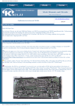
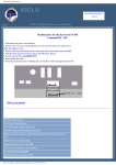
KB2LJJ Radio Mods Database
KB2LJJ
Home
Radio Mods Database and Manuals
www.r6-ru4montesecchieta.it
IZ5CCV
http://www.kb2ljj.com/data/kenwood/ts-440.htm (1 di 33)01/09/2009 0.07.16
KB2LJJ Radio Mods Database
Modifications for the Kenwood TS-440 and TS-440S
TS-440S Digital Audio Modification
TS-440 Fan Temperature Modification
Possible cure for TS440 showing dots only on display
Undocumented feature
Connection of the KENWOOD TS440S to a DATA
Kenwood Computer Interface Instructions
TS-440S increase the power by ALC control
TS-440 with PIN-Diods
TS-440S Operation with the MC-85
TS-440S Notch filter low frequency improvements
TS-440S Protecting Q33
TS-440S Case Screws binding in the heat sink
TS-440 RX Audio Mods
TS-440S SSB Power-adjustment
TS-440S Intermittent operation
TS-440S PLL unlock due to VCO #5
TS-440S PLL unlock due to VCO #1
TS440S mod for improved receive sensitivity of 0.5 to 1.6MHz
Circuit Improvements for the TS-440S
Possible cure for TS440 showing dots only on display
TS-440S Digital Audio Modification
NOTICE:
Please be very careful with your transcievers, and we accept no responsiablity for any damage that may be incurred, and
this modification may, and proably would be cause for any WARENTY to be DISCONTINUED.
This Modification allows for the Kenwood TS-440s transceiver to have the data audio on PIN 11 of the 13 pin DIN
connector ACC JACK 2. Later models may or maynot have a correction for this, but my PK-232, or for that fact NONE of
my TNC's would drive the audio to the PIN 11 of ACC JACK 2. Encountering this problem, and having another H.F.
transceiver I have been using the REMOTE connector, and using an audio input to the AFSK IN RCA type connector. This
would allow me to use the same cable with my TS-180s also. Anyway this modification moves the wire's from the AFSK
IN to the ACC 2 connector. This should only take about 20 to 30 minutes to preform this change, and most of the time is
used up with the removal, and replacement of the THREE covers of the transceivers cabinet.
The circuit boards to work with, are called:
DISPLAY UNIT (X54-1870-00) (C/4) This has the ACC 2 JACK.
SWITCH UNIT (X41-1610-00) (M/14) This has the AFSK INPUT.
http://www.kb2ljj.com/data/kenwood/ts-440.htm (2 di 33)01/09/2009 0.07.16
KB2LJJ Radio Mods Database
The eaiest way is to remove these two boards 4 screws hold the ACC 2 JACK, and 2 screws hold the AFSK INPUT board
in and they are located at the rear of the transceiver. If you are interested in following the SCEHMATIC in your manual,
the leads you will be working with are ANI, and GROUND which is the PURPLE LEADS, and the FSI lead and
GROUND, which are the GREEN leads.
The problem is that when kenwood designed this rig, they brought the DATA INPUT(ANI) from the ACC2 JACK to
connector J25 of the IF UNIT.
This coming in after the Processor, and Microphone Amplifier does not allow sufficent amplification of the signal, thus
very low, or no audio at all. What this modification does is swap at the rear of the RIG the FSI, and ANI signals, Which
also could be done on the IF UNIT board, and for some may actually be eaiser. In my case the leads were just a bit too
short to allow this modification to be accomplished on the IF UNIT.
MODIFICATION
1.
2.
3.
4.
5.
6.
7.
8.
9.
10.
11.
12.
13.
14.
15.
16.
Be shure to have on a work bench, and NO POWER APPLIED!
Remove the TWO BOTTOM covers, One MAIN cover, and the smaller cover to the REAR of the transceiver.
Remove the TOP cover.
Remove the FOUR screws holding the AUTOMATIC ANTENNA TUNER.
Place the transceiver on it's side with the BOTTOM towards you, and the FRONT to your LEFT.
Being very careful, remove the antenna tuner and allow it to hang.
Remove the TWO SCREWS that HOLD the AFSK INPUT board.
Remove the FOUR SCREWS that HOLD the ACC 2 JACK board.
Carefully from the inside of the transceiver, pull these TWO boards out.
Near the Bottom edge of the ACC 2 JACK board, is a TWO lead connettor, unplug this. The leads should be
PURPLE.
On the AFSK INPUT board, there is a 6 PIN connector, unplug this. The leads you will be working with are
GREEN in color.
Note how the PURPLE leads are connected to the connector itself, and remove these two leads by inserting a very
small screwdriver into the slot on side, and being very gental, push the leads out one at a time.
Now remove the GREEN leads the same manor.
Insert the GREEN leads into the 2 PIN connector, the BLAC lead is the GROUND, and the WHITE or perhaps
YELLOW is the AUDIO lead.
Insert the PURPLE leads into the 6 PIN connector, noting that the smaller lead is the AUDIO lead, and it connects
to PIN 2, the other lead, being BLACK goes into PIN 1.
Now reassemble in reverse order the BOARDS, and start at STEP 11, and work in reverse to STEP 1.
TS-440 Fan Temperature Modification
I don't know about you, but I don't think solid state equipment needs to run hot enough to fry an egg on. The fan on the 440
is set to come on at 50 deg C. That makes the heat sink hot enough that you can only put your hand on it for about 3
seconds without being in pain.
Looking at the schematic and pondering the situation, I decided that it would be quite easy to change the "trigger" point for
fan operation. This mod will do just that and not effect the "high-temp-shutdown" mode that is provided in case the fan
dies. Actually, it wouldn't be a bad idea to make the same sort of mod to that circuit too, but let's just do this one for now.
I'll put out another bulletin on this if I go into the failsafe circuit.
The fan is controlled by two sensing circuits on the FINAL UNIT. On the schematic, Q9(1/2) is the failsafe trigger that
activates the power down circuit in case the final reaches 80 deg C. It won't normally do this, even under continuous key
down conditions, unless the fan has failed.
Q9(2/2) is the stage that controls operation of the fan. It is a simple voltage comparator and therefore can be made to trigger
http://www.kb2ljj.com/data/kenwood/ts-440.htm (3 di 33)01/09/2009 0.07.16
KB2LJJ Radio Mods Database
wherever you want.
TH1 is a thermistor with a negative coefficient. That is, when the temp rises, the resistance goes down. This pulls the input to Q9(2/2) lower and lower until it is at or below the 2.26v reference that is present on the + input of the same stage.
At that point, the output flips high and turns on Q8, thus turning on the fan. By raising the reference voltage at the + input,
the TH1 voltage will fall to the reference voltage sooner and turn on the fan at a cooler temperature. By clipping the top
loop of R27 on the final unit (2.2k res. that provides reference voltage) and temporarily inserting a 5k precision multi-turn
pot in series with it, I determined that I liked the way it operated with about 800 ohms extra resistance in the circuit.
I then installed an 820 ohm fixed resistor in series with the cut loop. I also put a very small dab of silicon seal between the
new "hung" resistor and the ferrite transformer right next to it so that there would be no added strain on the remains of R27.
The alternative would be to remove the final unit completely and do the mod the right way, replacing the complete R27
with a 3k resistor. This was a step that I didn't really want to perform on a two week old rig. When you choose your series
resistance, remember that the more resistance you add to it, the sooner the fan will turn on. If you go too high, it will be on
all the time.
This modification brings the fan on at least 10 deg. earlier. By the way, my only reservation about this mod is the added
wear and tear on the fan unit itself. I have been buying parts from Kenwood for about 10 years now and they have always
seemed remarkably inexpensive. Ordering a spare fan to have on hand seems like a very reasonable thing to do if you are
worried about it.
Possible cure for TS440 showing dots only on display
The most common reason for the the display to show only dots, is that one of the phase locked loops is not locked. So take
of the top cover. You will be looking at the IF unit. This board is mounted in a hinged frame. It hinges on two screws near
the front pannel sides. So remove the other two screws near the final unit instead and hinge the IF board towards you. You
now uncovered the PLL unit.
There are five PLL's on this board. Each one has a pin indicating if its loop is locked or not. So get out a volt meter and set
it for 5 volts full scale. Now check pin 2 for each of the following IC's. IC18, IC1, IC4, IC9.
Also check pin 7 of IC17. If all the loops are locked, you would see a steady voltage there in the neighbourhood of 4.7
volts. If any of the loops is not locked, one of these pins has a voltage well below 1 volt.
Note the IC number so you can look up which VCO you may have to tune a bit so it will lock again.
IC18 VCO#5 T20
IC1
VCO#4 T1
IC4
VCO#3 T2
IC9
VCO#2 T9
The above are all located on the PLL board.
The VCO for IC17 is actualy one out of four different VCO's selected on the RF board. Which one of these depends on
what band is selected.
If you have display dots on all the bands, then you have no problem with the PLL made up with IC17. So you only have to
adjust either T1, T2, T9 or T20.
Now here it goes. Make sure you have an alignment tool that isn't to small or to large for the slots in the slugs in the coils
(T1, T2, etc.) Also, absolutely don't turn any other coil than the one that belongs to the unlocked PLL. If you do so anyway
without a service manual and proper equip- ment, then you are likely stupid.
Only turn the indicated slug. First turn it 1/4 clock wise and see if it is ok now. If not, turn it 1/4 counter clockwise and see
if it works. I suggest that you don't try more than one half turn either way. If you think that it needs to go that far, it likely
has an other problem.
If the display dot problem only shows up on some but not all band, send me a note and I will see if I can help you.
The correct way would be to use a good voltmeter and follow the service manual for this adjustment. But in most cases, the
http://www.kb2ljj.com/data/kenwood/ts-440.htm (4 di 33)01/09/2009 0.07.16
KB2LJJ Radio Mods Database
above will do fine. I don't work for Kwood, I don't have a 440. Just a service manual for one. But I did cure some of the
above problems.
User comment Kenwood TS-440S. Only dot on display
On our work-shop maintenance, one TS-440S serial 20638, was solved by turning core of L20 1/4 turn to left because the
IC18 was out of lock.
Latter, testing all along the total frequencies and bands, the 5 PLL´s was maintaining the phase lock. In some other sets,
the glue on the 5 PLL´s and in the 4 VCO´s frequently produce a quimic action with the cooper wires of parts and make a
conductive, not desired way, from parts to parts, causing that oscillation stop. Remove the glue with Thinner. Latter some
minutes the glue will be removed easily. Latter check all PLL voltage and all VCO output for a correct lock-up. Check on
all bands.
User comment Dots on TS440 between 7.5 to 22 MHz
Some months ago I repaired a TS440 where the PLL is unlocked above 7.5 MHz to about 22 MHz. Although I have
returned the manual to the owner along with the unit, my memory recalls the failure of a 33pf bypass capacitor near the
transistor responsible for switching in the appropriate VCO. The small ceramic capacitor measured 180 Ohms and was
low enough drop the voltage normally supplied to the transistor to ground.
Knowing this may be of benefit to others because if other capacitors fail to a lesser degree than I have seen, it may still
provide a workable but lower voltage to the VCO. And as the voltage has changed, so will the frequency of the VCO.
This may be one other reason why some can be fixed by retuning the coil. So be aware, if the problem reoccurs down the
track, you may have a capacitor that is slowly decreasing in value and may eventually stop the VCO from working
because the voltage to the transistor is too low. Good luck
User comment ts-440 dots only on display
When my TS-440S/AT was sent up from Melbourne Australia the guys at Australia post must have knocked it around
because i had this problem from 22MHZ up but after a fiddle with T21 on the RF unit my problem was solved. I believe
there are 4 or 5 different coils like this for the different segments of 30KHZ to 30MHZ that this radio tunes
User comment: TS440, repair PLL unlock, dots on display 22MHz and up.
Concerning PLL unlock at the Kenwood TS-440, I did the following:
First I found a poor lock of VCO-5 on the PLL-unit.
Removing the glue with a solvent and replacing L41 from VCO-5 on the PLL-unit (top side of the transceiver) did not
made any improvement.
I could not measure any high impedance conductivity of the glue anyhow. So, I did not remove the glue around the
VCO’s at the RF-unit (at the bottom side of the transceiver).
The problem was, like Bill K0ZL mentioned before at this site:
I found bad solder joints around VCO-4 (67.05-75.05MHz) on the RF unit near D44 and around VCO-5 (36.22MHz) on
the PLL-unit, during pressing on the print board at different places. I noticed a change in noise during pressing. I used a
pair of tweezers, moving carefully the components, in order to find the bad spot.
So, I re-soldered all suspicious joints on the print board.
Et voilá, everything works ok again! Hope you find the problems too!
Success and 73 de PA0HER, Holland
http://www.kb2ljj.com/data/kenwood/ts-440.htm (5 di 33)01/09/2009 0.07.16
KB2LJJ Radio Mods Database
Undocumented feature
The TS440 is nice. Here's what I've found out about it that isn't in the operation manual (in some random order):
Diode options: There are a bunch of configuration options controlled by clipping or inserting diodes on the back of the
control board. You get to it by taking the top and bottom covers off (a bunch of silver screws), loosening the front panel (4
flat-head silver screws, NOT the black ones). Then you have:
diode
----D65
D66
D67
D73
D78
D79
D80
controls
-------mode confirmation
display resolution
memory protect
CW shift
WARC 24MHx band tx
WARC 18MHz band tx
General Coverage tx
in
---------Morse
100 Hz
none
800 Hz
disabled
disabled
disabled
out (cut)
---------single beep
10 Hz
on
400 Hz
enabled
enabled
enabled
Self-Test: You can run a rather complete test of the control logic by the built-in "semi-self-test", a series of 56 routines. To
run this, turn the unit on whilst holding the AM and T-F SET switches pushed in. It changes to the next test when you turn
the VFO knob clockwise. Turn the power OFF to reset the unit.
Test
What it does
-----------------------------------------------------0
all positions in display light
1
all segments in display dark
2
all positions in display light
3
all segments in display dark
4
one digit lighted (rightmost)
5
next digit lighted
6
next digit lighted
7
next digit lighted
8
next digit lighted
9
next digit lighted
10
next digit lighted
11
next digit lighted
12
next digit lighted
13
next digit lighted
14
next digit lighted
15
next digit lighted
16
next digit lighted (leftmost)
17
beeper sounds
18
beeper silent
19
all mode LEDs ON
20
all mode LEDs OFF
21
receive
22
transmit
-------------------------------------------------------------------------The following tests change internal signals. They are most useful if you are trying to trace the circuits controlled by these
signals.
You'll need a s service manual (or at least a schematic) to made reals sense of these.
23
Band select - all lines high
http://www.kb2ljj.com/data/kenwood/ts-440.htm (6 di 33)01/09/2009 0.07.16
KB2LJJ Radio Mods Database
24
25
26
27
28
29
30
31
32
33
34
35
36
BAND select - all lines low
PD select - all lines high
PD select - all lines low
ENF select - all lines high
ENF select - all lines low
ENP select - a:ll lines high
ENP select - all lines low
RES select - all lines high
RES select - all lines low
CO select - all lines high
CO select - all lines low
AX select - all lines high
AX select - all lines low
these next tests check the outputs of the 8255 parallel port interfaces, which select several internal functions.
37
38
39
40
41
42
43
44
(IC2) port A all lines high
(IC2) port A all lines low
(IC2) port B all lines high
(IC2) port B all lines low
(IC2) port C0-C3 high, C4-C7 low
(IC2) port C0-C3 low, C4-C7 high
(IC53) port C all lines high
(IC53) port C all lines low
Following display busy lines and scan lines in the rightmost 9 digits of the display. You will push buttons to cause the digit
to change from a 1 to a 0 indicating that the associated button has been pushed.
test
bit8
bit7
---------45
LOCK
46 (none)
47 (key scanner)
48
1
6
49
2
7
50
3
8
51
4
9
52
5
0
53
bit6
---AT
bit5
---Mic UP
V/M
M>V
SCAN
M.IN
CLEAR
ENT
RIT
XIT
T-Fset
1Mhz
DOWN
bit4
---Mic DN
bit3
---PTT/AT
VOICE
A/B
SPLIT
A=B
dip1
UP
bit2
----
bit1
----
bit0
---VS1
dip3
dip2
dip8
dip4
dip6
dip9
dip5
dip7
dip10
(the digits 0-9 are on the front panel keyboard; dip2-dip10 are the segments of S50, the SSB frequency response dipswitch
on the rear of the control unit printed circuit board.)
54 not used
55 not used
56 END
http://www.kb2ljj.com/data/kenwood/ts-440.htm (7 di 33)01/09/2009 0.07.16
KB2LJJ Radio Mods Database
Serial interface
The TS440 has a serial ASCII interface option. You have to insert two chips into sockets on the back of the control unit
circuit board to take advantage of this. IC54 is an 8251A Uart, and IC55 is a CD4040 divider. These chips are available
from Kenwood together with a interface manual, or you can buy them at your local chip shop for about $6.00 or so. When
inserted, the transceiver speaks 4800 baud ascii in/out the 6-pin DIN connector ACC-1 on the rear. The signals are from the
8251, but are inverted in a 74LS04 and RFI filtered before being brought out to the world. An interface box with inverter,
RFI filter, power supply, opto-isolator, RS232 level shifters, and power supply is available from Kenwood for about
$49.00, or you can build your own.
(Depending on how much your computer radiates and how sensitive to RF it is, you may only need 5v, +/-12v, a 74LS14,
MC1488, and MC1489. If your computer has a TTL level serial port, perhaps all you'll need is the 74LS14. If you're not
confident of being able to solve the possible digital/RF interface problems yourself, the $49 interface is proably a good
buy.)
pin
--1
2
3
4
5
6
ACC-1 Serial Interface
signal
---------------------------------------------------signal ground
data from transceiver
data to tranceiver
cts to transceiver - computer can throttle output
cts to computer - transceiver can throttle input
no connection
SSB frequency response dipswitch: located on the back of the control unit, this adjusts the frequency response of the upper
and lower sideband modulators to compensate for component variations. Changing it isn't a good idea, since you have to
have a two-tone oscillator and have to reset the carrier suppression adjustment if you do. The service manual explains this
process; I'm including this here so that people who have been wondering what the dipswitch does won't screw themselves
by flipping switches to see what happens.
A few adjustments you should know
A few adjustments you should know about (read the service manual before you tweak wildly on these!):
tweaker
------RF-VR3
RF-VR6
IF-VR2
IF-VR3
IF-VR4
IF-VR9
IF-VR10
what it does
----------------------------------------------FM Microphone Gain
FM Deviation - set to 4.6KHz on dev meter
S-meter zero - set to zero with 50 ohm dummy load
S-meter S9 - set to S9 with 40dbu input 14.175MHz USB
Squelch threshold - close at 12 o'clock with
mode = CW and filter WIDE
CW side tone level - as you like it
Beep tone level - as you like it
Someone wanted to know what the difference between the DATA connections on ACC-2 and the AFSK connectors was.
On output, none; the AFSK and the DATA out pin on ACC-2 are connected together, and are fed from the high side of the
volume control - they are receiver audio BEFORE the cw sidetone, beeper, and voice response unit are mixed in, and
should be a constant level independent of the AF gain setting. The AFSK input is different from the DATA IN connection;
http://www.kb2ljj.com/data/kenwood/ts-440.htm (8 di 33)01/09/2009 0.07.16
KB2LJJ Radio Mods Database
AFSK and microphone signals both go through the mike preamp and speech processor; the DATA input bypasses both.
The MIC GAIN pot does control all three input levels.
(as a note, you can tap preamped/processed audio OUT of the DATA IN connection, since it is just a tap on the output of
the preamp/processor. This is also the feed into the FM modulator. But NOTE that the MIC GAIN pot doesn't adjust the
mic gain on FM - there is a separate tweaker for that.)
TS-440S modification to use antenna tuner
Remove case from rig. Remove (4) screws that holds antenna tuner in place. Next slide antenna tuner out to get to the coax
connections. Remove the in coax attached to antenna tunerfrom FO connector on filter unit (X51-1340-00). Remove coax
from out connector on antenna tuner and install in FO CONNECTOR ON FILTER UNIT. Unplug and remove switch unit
(X41-1610-00 N-14) from rig.
Remove short wire from antenna connector to PC BOARD. Cut coax on the in connector of antenna tuner in half and
connect cut end to switch unit PC BOARD Where short antenna wire was removed and shield to ground. Solder other half
of coax to antenna connector and shield to ground, and plug other end into out conector of antenna tuner. Your still have
control of antenna tuner with auto and thru switch. It works very well. Maybe someone can use this idea.
TS-440S display calibration
I found there was some shift in the reference oscillator frequency of my TS-440S. This can be noticed and corrected as
follows:
1. Remove the top and bottom covers from thd radio.
2. Do not disconnect the speaker cable.
3. Connect the supplied calibration cable between RF Unit and PLL unit, as shown in "Kenwood TS-440S Instruction
Manual" on Page 24 in Section 5-8-3.
4. Set VFO A to 10.001.00 MHz LSB and VFO B to 9.999.00 MHz USB.
5. Pushing the A/B function button, you can have different audio signals, if that 36 MHz reference oscillator is
miwadjusted.
6. Using a small flat bladed scredriver, adjust trimmer capacitor TC1, near connector 8 of the PLL Unit (the location
shown in Instruction Manual in the same section as above) until those audio frequencies from VFO's A and B are
equal.
7. Disconnect the calibration cable and reassemble the radio. This procedure can be done by ear with good accuracy
without any measuring equipment. WWV is too weak here in Finland to use it as comparative signal for the
procedured described in "Instruction Manual", Section 5-8-3.
http://www.kb2ljj.com/data/kenwood/ts-440.htm (9 di 33)01/09/2009 0.07.16
KB2LJJ Radio Mods Database
Connection of the KENWOOD TS440S to a DATA
Connection of the KENWOOD TS440S to a DATA terminal such as a Kantronics KAM using the rear ACC2 13 pin jack.
____ 4
GROUND ___ |
|____ 8
|
|___ 12
2
1
7
6
5
11
10
/
3
MIC
____________/
9____________
|
13
|
|
|
|
|
\_/
\_/
=====
=====
|
|
|___________________|
|
|
|
|
PTT
Pins
|
Application
----------------------------------------------------------------3
4
8
12
9
13
Data output - not used as the level is very low
the prefered connection is via the speaker output
this also allows fine adjustment of level to
enable best decoding. (A switch on the speaker to
'mute' it when required is a good idea.)
Ground - you may have to experiment with these
connections to eliminate RF feedback and noise.
Here they are all strapped.
Mic mute - prevents audio pickup from the mic when
earthed. By connecting to the PTT line as shown
through a diode automatically MUTES the mic when
using data. When the front panel PTT or MIC PTT
are used the microphone is 'live'.
Standby - PTT which when taken to ground puts the set
'on air'. By connecting through a diode as shown
doesn't affect the PTT operation but allows auto
mic muting.
The diodes used can be virtually anything, here they are IN4148.
The INPUT audio to pin 11 must be quite a high level. If using a KAM you are certainly going to have to change the HF
LEVEL JUMPER in the KAM. The level of the KAM as shipped suites connection to the FRONT PANEL MIC but not the
rear connector, you can however correct this with the jumper. People using the PK232 have complained of NO TX
AUDIO, I suspect the level is so low that only local minitoring will show a level present.
http://www.kb2ljj.com/data/kenwood/ts-440.htm (10 di 33)01/09/2009 0.07.16
KB2LJJ Radio Mods Database
Kenwood Computer Interface Instructions
These Instructions are TS-440 specific, but the basics also apply to the TS-940, TS-811 and TS-711.
It is possible to save yourself a few dollars and lose nothing in quality by buying the parts to upgrade your Kenwood radio
for computer control. Just purchase the parts were you find them and install them using the instructions in the Radio's
Manual.
IC 54 is a uPD-8251-AC
Serial Communications Interface.
Commonly called an 8251A
($1.89 Mail Order)
IC 55 is a TC-4040-BP
12 Stage CMOS Divider.
Commonly called a 4040
($0.69 Mail Order)
The IC-10 Interface Kit from Kenwood Contains ONLY these two parts and less instructions than are in this file. The only
thing you are going to miss, is the $22+ price tag on the IC-10 Kit.
Signals are
Baud rate is
Format is
TTL levels (NOT RS-232)
4800 (1200 Opt.)
ASCII Serial; 1 Start, 8 Data, 2 Stops
The Baud rate may be changed to 1200 Baud by removing jumper W50 and installing a jumper from the left pad to the
center pad as viewed from the front of the radio. This will become obvious once you have the radio opened up. Many other
Baud rates are possible, just look at the schematic.
As long as you are in the radio, lift D-60 to enable the 10 Hz. display. The main tuning knob is varing this digit, so you
might as well see it. It also helps when using RIT/XIT as the RIT/XIT display does not resolve the 0.01 KHz. digit. This
Modification is in the Radio's Book.
Not in the book is the fact that if you lift D-80 and do an MPU reset, you will be able to transmit on any frequency between
1.5 and 30.0 MHz. This means you will be able to work the Mars nets, Etc. Do not transmit out of band. It is illegal even if
it is accidental.
Some computers use TTL levels on their serial ports. If so, here is a time when you will not have to convert it to RS-232.
The IF-232 Interface from Kenwood is a 1488 and a 1489 chip in a box. These are an RS-232 Quad Line Driver and
Receiver and are available at Radio Shack for $1.29 Each. Here is an easy project that will save you a lot over the $69+
Kenwood price of the IF-232 Interface. The 1488 needs a + and - supply.
Unregulated + and - 12vdc is just fine. Get the +5 vdc for the 1489 by putting a 7805 regulator on the +12 vdc supply. 100
mA.
is about the max you'll draw, so the smallest transformer you can find will still be plenty large. Don't forget to series up two
of each gate to cancel the inversion that the 1480's produce.
ACC-1
Connector
Use a 6 Pin DIN Connector.
(Radio Shack $1.29)
Pin
Signal Comments
________________________
1
2
Gnd
TXD
Signal Ground
Serial Data from Radio to Computer
http://www.kb2ljj.com/data/kenwood/ts-440.htm (11 di 33)01/09/2009 0.07.16
KB2LJJ Radio Mods Database
3
4
5
6
RXD
CTS
RTS
Serial Data from Computer to Radio
Computer Ready; (Radio Input)
Radio Ready;
(Radio Output)
No Connection
Pins 4 and 5 may be left Unconnected.
***** Command Description for Kenwood Computer Interface *****
______________________________________________________________
Auto Information
________________
AIn;
The Radio Will Send the Status Info Automatically
Whenever the Operator Manually Varies any Function
on the Radio which is Covered in the IF; Command
Where
n = 0 for Auto Info OFF
1 for Auto Info On
The Status Information Will be Sent in the Form :
As defined in the IF; Command
Display Memory
______________
DMnnnn;
This is a Factory Diagnostic Function
and is of no practical use to the operator
The Contents of the MPU Memory will be Read
Where
nnnn = MPU Address (0000 Thru FFFF (HEX))
The Contents of the MPU Memory Will be Sent in the Form :
DMnnnn-aabbccddeeffgghhiijjkk;
Where
nnnn = MPU Address (0000 Thru FFFF (HEX))
aa~~kk = Hex Number Pairs Of Next 16 Locations
Down
____
DN;
The Frequency or Memory Channel
Will Decrement One Step
Frequency VFO A / VFO B Request
_______________________________
FA;
FB;
The Frequency in the Selected VFO Will be Read
The Frequency Will be Sent in the Form:
FAggmmmkkkhhh;
or
FBggmmmkkkhhh;
Where
gg = GHz. Value
http://www.kb2ljj.com/data/kenwood/ts-440.htm (12 di 33)01/09/2009 0.07.17
KB2LJJ Radio Mods Database
mmm = MHz. Value
kkk = kHz. Value
hhh = Hz. Value
Frequency VFO A / VFO B Select
______________________________
FAggmmmkkkhhh;
FBggmmmkkkhhh;
The VFO Selected Will be Set to the Frequency Defined
Where
gg = GHz. Value (May be sent As 00 or Spaces)
mmm = MHz. Value
kkk = kHz. Value
hhh = Hz. Value
Function Select
_______________
FNn;
The Function Defined Will
Where
n = 0 for
1 for
2 for
be Selected
VFO A
VFO B
MEMORY
Identify Model Request
______________________
ID;
The Model of the Radio Will
ID00n;
Where : n = 1 for a
n = 2 for a
n = 3 for a
n = 4 for a
be sent in the Form :
TS-940 (*)
TS-811 (*)
TS-711 (*)
TS-440
Read Information Request
________________________
IF;
The Status Information Will be Sent in the Form :
IFggmmmkkkhhh
snnnzrx yytdfcp
Where
gg~~hhh = Value as defined in FA Command
s = "+" or "-" Value of RIT/XIT
nnn = Value of RIT/XIT (n.nn kHz.)
z = "0" (Not Used in TS-440)
r = Value as defined in RT Command
x = Value as defined in XT Command
yy = Memory Channel No.
t = 0 for Receive
1 for Transmit
d = Value as defined in MD Command
f = Value as defined in FN Command
c = Value as defined in SC Command
p = Value as defined in SP Command
Lock Knob
_________
LKn;
The Manual Frequency Control Functions Will be Disabled
Where
n = 0 for Lock OFF
http://www.kb2ljj.com/data/kenwood/ts-440.htm (13 di 33)01/09/2009 0.07.17
KB2LJJ Radio Mods Database
1 for Lock ON
Memory Channel Select
_____________________
MCxmm;
The Memory Channel Defined Will be Selected
Where: x = Don't Care
(Use "0" or Space)
mm = Memory Channel No. (00 thru 99)
Mode Select
___________
MDn;
The Mode Defined Will
Where: n = 1
2
3
4
5
6
Be Selected
for LSB
for USB
for CW
for FM
for AM
for FSK
Memory Read
____________
MRnxrr;
The Memory Channel Defined Will be Read
Where: n = 0 for RX VFO
1 FOR TX VFO (Split Channels Only)
x = Don't Care
(Use "0" or Space)
rr = Memory Channel No.
(00 thru 99)
The Memory Information will be sent in the Form :
MRn rrggmmmkkkhhhdz
;
Where: n = 0 for RX VFO
1 FOR TX VFO (Split Channels Only)
rr = Memory Channel No.
(00 thru 99)
gg~~hhh = Value as defined in FA Command
d = Value as defined in MD Command
z = "0" (Not Used in TS-440)
(Note: Four trailing Spaces)
Memory Write
____________
MWnxrrggmmmkkkhhhdzxxxx;
The Memory Selected Will be Set to the Frequency Defined
Where: n = 0 for RX VFO
1 for TX VFO (Split Channels Only)
x = Don't Care (Use "0" or Space)
rr = Memory Channel No.
(00 thru 99)
gg~~hhh = Value as defined in FA Command
d = Value as defined in MD Command
z = "0" (Not Used in TS-440)
RIT/XIT Clear
_____________
RC;
The RIT/XIT will be set to 0.00 kHz.
http://www.kb2ljj.com/data/kenwood/ts-440.htm (14 di 33)01/09/2009 0.07.17
KB2LJJ Radio Mods Database
RIT/XIT Down
____________
RD;
The RIT/XIT will Decrement by 0.01 KHz. (10 Hz.)
RIT/XIT UP
__________
RU;
The RIT/XIT will Increment by 0.01 KHz. (10 Hz.)
TS-440S increase the power by ALC control
This article also tells how to increase the power of the TS-440 by adjusting the internal ALC control. The procedure is
applicable to other rigs.
Illustration captions:
1. Remove 17 screws holding on the bottom and top covers. The bottom cover comes off, and the top cover is carefully
removed and put next to the radio. It is till connected via the speaker wire.
2. Gain access to the front of the unit by removing two top side screws and loosening two bottom side screws. This
allows the front assembly to swing open.
3. Remove the shiny silver control board protection plate. This requires removing two screws on the top and three
screws on the bottom. Lift the plate out completely. Locate diode D-80 in the bottom left-hand corner. Snip it for allband transmit.
4. Now locate D-66 and snip. It adds 10 Hertz readout to your digital frequency display.
5. Carefully reassemble the control plate using a magnetized tiny screwdriver to hold the five tiny screws in place.
Don't pinch any wires. Also, close up the front and replace the top and bottom covers with 17 screws.
6. Connect power. Depress A=B switch and turn on the power simultaneously. This resets the microprocessor for allband transmit and 10 Hz frequency display.
User comment: ALC -POWER MOD
This is the mod for all band transmit and the ad 10HZ to the digital display not the ALC power adjustment as specified!!!
http://www.kb2ljj.com/data/kenwood/ts-440.htm (15 di 33)01/09/2009 0.07.17
KB2LJJ Radio Mods Database
TS-440 with PIN-Diods
Hallo, ts440-owners!
Recently i read about an upgrade for the ts440 concerning the bandswitc-diods.
Originally, there are simple switching types built in. For better high level performance i decided to replace
D2,3,4,5,6,7,...23,68 by the ECG553 PIN Diode.
The result was not so doubtless positive. i could not really confirm an advantage. unfortunately, i have no measuring
equipment for determining the intercept point.
But on 40m , where i sometimes have problems using a 160/80/40/30/20m 5-band fullsize dipole, i still suffer
intermediation effects.
I can not really say, if it is much better after the replacement, but i'm sure, it isn't worse (hi).
Some remarkable progress was the usage of the built-in tuner in the receiving pass. that really helped espacially on the
10mc band to overcome the problems of interference.
But best results and a final solution i found in using an external Preselector as described in the cq-dl several times.
That really did it! Of course you need to add on to cinch connectors at the rear panel.
It is no real problem.
so, my advice:
don't modificat the diodes or use of the tuner for reception.
The result is too poor compared with that of an external Preselector.
TS-440S Operation with the MC-85
Author: Trio-Kenwood Communication, inc.
Service Bulletin no. 947 (20-1-1989)
With some TS-440S transceivers, insufficient modulation may occur when the MC-85 compression switch is turned on.
This may be caused by too much of a voltage drop across resistor R172 on the IF unit of the transceiver . If this is found to
be the case, change the resistor from 1K ohm to 100 ohms.
Required part
100 Ohm, 1/6 Watt resistor (RD14CB2C101J)
PROCEDURE:
1. Disconnect the power supply and antenna from the transceiver.
2. Using a #2 Phillips screw driver, remove the 9 screws from the top cover of the transceiver. Remove the cover and
unplug the speaker wire.
3. Locate resistor R172 on the component side of the IF board (Figure 1).
4. Using a #1 Phillips screw driver, remove the 7 screws that secure the IF unit to the chassis of the transceiver.
5. Pull the board up and rotate it towards the front of the transceiver to expose the foil side of the board.
6. Desolder and remove resistor R172 from the board.
http://www.kb2ljj.com/data/kenwood/ts-440.htm (16 di 33)01/09/2009 0.07.17
KB2LJJ Radio Mods Database
7. Install and solder the 100 ohm resistor in place of R172.
8. Assemble the transceiver by reversing steps 1 - 5.
This modification may be covered under warranty.
Time required for this modification is 0.5 hrs or less.
TS-440S Notch filter low frequency improvements
Author: Trio-Kenwood Communication, inc.
Service Bulletin no. 948 (20-1-1989)
The low frequency attenuation characteristics of the notch filter can be improved by reducing the input level to the notch
filter chip (IC1). To compensate for the loss of input level, the amount of negative feedback to the audio amplifier (IC7)
will need to be reduced. This modification is already incorporated in all models beginning with serial number 704XXXX.
Required parts:
120K Ohm, 1/6 Watt resistor ........ RD14CB2C124J
390 Ohm, 1/6 Watt resistor ........ RD14CB2C391J
1. Disconnect the power supply and antenna.
2. Using a #2 Phillips screw driver, remove the 9 screws from the top cover. Remove the top cover from the
http://www.kb2ljj.com/data/kenwood/ts-440.htm (17 di 33)01/09/2009 0.07.17
KB2LJJ Radio Mods Database
transceiver and unplug the speaker wire.
3. Locate resistors R86 and R229 on the component side of the IF board (Figure 1).
4. Using a #1 Phillips screw driver, remove the 7 screws that secure the IF unit to the chassis of the transceiver.
5. Pull the board up and rotate it towards the front of the transceiver to expose the foil side of the board.
6. Desolder and remove both resistors from the board.
7. Install and solder a 102K ohm resistor in place of R86.
8. Install and solder a 390 ohm resistor in place of R229.
9. Assemble the transceiver by reversing steps 1 - 5.
This is an optional change that may not be performed under warranty.
Time required for this modification is 0.5 hrs or less.
http://www.kb2ljj.com/data/kenwood/ts-440.htm (18 di 33)01/09/2009 0.07.17
KB2LJJ Radio Mods Database
TS-440S Protecting Q33
Author: Trio-Kenwood Communication, inc.
Service Bulletin no. 949 (20-1-1989)
If pin 7 (RL) of the remote connector is accidentally connected to ground, current from the 14 volt line (14L) will damage
transistor Q33 on the IF unit. This will prevent the radio from transmitting. To protect Q33, a 4.7 ohm resistor should be
installed in series with the RL line on the foil side of the IF board. In the event that pin 7 is connected to ground, the
resistor will open, but the transceiver will still be capable of transmitting.
Required part:
4.7 Ohm, 1/6 Watt resistor ........ RD14CB2C4R7J
1. Disconnect the power supply and antenna from the transceiver.
2. Using a #2 Phillips screw driver, remove the 9 screws from the top cover of the transceiver. Remove the cover and
unplug the speaker wire.
3. Locate connector 19 on the IF unit.
4. Using a #1 Phillips screw driver, remove the 7 screws that secure the IF unit to the chassis of the transceiver.
5. Pull the board up and rotate it towards the front of the transceiver to expose the foil side of the board.
6. On the foil side of the board, locate the trace that is connected to pin 3 (brown wire) of connector 19.
7. Using a craft knife, cut the trace coming from pin three so as to open the foil trace.
8. Solder the 4.7 ohm resistor across the now open trace (i.e. in series with the trace).
9. Assemble the transceiver by reversing steps 1 - 5.
http://www.kb2ljj.com/data/kenwood/ts-440.htm (19 di 33)01/09/2009 0.07.17
KB2LJJ Radio Mods Database
This is an optional change that may not be covered under warranty.
Time required for this modification is 0.5 hrs or less.
TS-440S Case Screws binding in the heat sink
http://www.kb2ljj.com/data/kenwood/ts-440.htm (20 di 33)01/09/2009 0.07.17
KB2LJJ Radio Mods Database
Author: Trio-Kenwood Communication, inc.
Service Bulletin no. 950 (20-1-1989)
Occasionally a case screw that fastens to the heat sink of the TS-440S will cross thread or bind when it is being inserted or
removed. Binding may be caused by tooling marks on the screw or by burrs on the tapped threads in the heat sink. When a
screw starts to bind, DO NOT TRY TO FORCE IT! as this may cause the head to shear off. If the screw is being removed
and it starts to bind, return the transceiver to KENWOOD. Do not make attempts to remove the screw. In addition, if a
transceiver is being brought to you with a scrw sheared off, return the unit to KENWOOD. Do not attempt to drill out the
screw.
If a screw starts to bind when it is being installed, carefully back it out. Inspect the screw for marks or burrs and replace it if
it is questionable. Since the threads in the heat sink may be causing the screw to bind, they should be cleaned by running a
3 x 0.5 mm tap into each hole.
The tap is inexpensive and can be obtained at may of the larger hardware stores.
To avoid cross threading, make sure the covers are properly aligned when they are being installed. Proper alignment means
that there is a clear path for the screw to turn into the heat sink.
This assures that the screw does not rub against the case and result in it turning into the heat sink at an angle.
TS-440 RX Audio Mods
Here's some easy modifications to improve the rx audio fidelity of Kenwood TS-440's. All references below are to the IF
board component designations.
●
Increase C60 to a .47uf or 1 uf. This will increase low frequency response on all modes.
●
Decrease C51 to .01 uf. This will increase high frequency response on SSB/CW.
●
Try removing R263 (tacked on the bottom of the board on my early production unit). This will lower in amplitude
the audio coming out of the detectors and improved the smoothness (a real technical term) of the audio, especially
on AM signals.
And, of course, I take no responsibility for anything you do to your radio. Be careful. The IF board on the 440' is about the
easiest one to get at.
73/Dave [email protected]
http://www.kb2ljj.com/data/kenwood/ts-440.htm (21 di 33)01/09/2009 0.07.17
KB2LJJ Radio Mods Database
TS-440S SSB Power-adjustment
From: PA3FKO
Hello TS 440 user..
The last few weeks I've seen questions of how to make the power in SSB mode for the TS440S adjustable without changing
the Mic-Gain. It's a very easy job to do.
Take off the top cover of the rig.
At that moment you have a sight on the first unit (IF-Unit)
Than you have to look for Diode 49.
You will find Diode 49 at about 5 CM from the backend of the unit and about 6,5 CM from the left side of the unit.
Just next of C138 and between plug 38? (red/orange wires) and plug 26 (black-cover/blank wires) Just cut that Diode 49,
bend one part a little away and leave the part's where they are. It's the best way to do I think.
Replace the top cover.
From now on it is possible to adjust only the power in SSB mode by just turning the CARRIER Control at the front of your
rig and leave the Mic-gain for where it is.
Turning counter clock will minimize the power until a 20mW or something like that.
Because most TS440 users haven't used their carrier control that much I think it's better to pull off the MIC/CAR knobs and
spray some contact cleaner in the shafts. (I know, it's not the best way).
When you switch your rig into the CW mode you can adjust the power in what you like, switch the mode in to USB or LSB
and if it is correct the power will not come above the level that what you have adjusted in the CW mode.
Just simple , isn't it?
Of course you will do this all in your own responsibility because I won't take any!!! Agree?
Vy 73 Willem.
User commentt: yaesu 757 gx
hi, i read and mod the kenwood ts440s bi cut d49 works good tank you. how can i mod the drive on ssb without touch the
mike. for the yaesu 757 gx.
TS-440S Intermittent operation
Author: Trio-Kenwood Communication, inc.
Service Bulletin no. 952 (24-1-1989)
When intermittent problems such as erratic display, loss of front panel control, or frequency lock-up are encountered, the
PLL and Control circuits must be checked to determine which circuit is malfunctioning. While any number of components
may cause such problems, if the Control circuit is suspect, there is a possibility that the ROM socket is at fault. The socket
should be tested to determine if it is making good electrical contact with each pin on the ROM. If it is found to be defective,
remove the socket and solder the ROM directly to the board. The ROM is IC52 on Control unit (B/2). It should be noted
that units with serial number of 909xxxx and above do not incorporate a socket.
Caution
Removing the socket requires good soldering skills. The ROM is mounted on the Digital A unit and is designated as IC2.
The board, being double sided, has solder connections on both component and foil sides. When the socket is removed, it is
very important to insure that each pin is completely solder free. Having to pry up on the socket means that it is not
completely desoldered and will cause the circuit foils to tear.
http://www.kb2ljj.com/data/kenwood/ts-440.htm (22 di 33)01/09/2009 0.07.17
KB2LJJ Radio Mods Database
When performing any work on the Control boards, CMOS handling techniques must be observed. Such techniques include
using a grounded or isolated soldering tip, avoid touching the pins of IC chips with your fingers, and ground yourself with a
wrist ground strap.
To remove the socket:
1. Disconnect the power supply and antenna.
2. Remove both the top and bottom covers from the transceiver. Disconnect the speaker cable from the transceiver.
3. Remove 2 countersunk screws from each side of the front panel chassis and gently pull the front panel forward.
4. Loosen the 5 round head screws (2 on top and 3 on the bottom) that secure the shield plate inside the front panel and
then remove the plate.
5. Set the transceiver on its left side and fold the front panel back to expose Control board (B/2). Do not stress the
cables.
6. While avoiding contact with the pins, remove the ROM (IC52) and set it aside on anti-static foam.
7. Unplug connectors 56 - 58 from Control board (B/2).
8. Remove 3 brass screws from Control board (B/2). Do not remove the fourth screw that connects to the angle
bracket. Instead, remove the brass screw from the Control board (A/2) so the angle bracket stays with the top board.
9. Fold the top board towards the body of the transceiver. Be very careful not to stress the flat ribbon cables that are
soldered between the two boards.
Note
If the foil side of the board id not sufficiently exposed for desoldering purposes, remove the 3 hex bosses from the bottom
Control board. Pull both boards forward and open them like a book to allow the best access to the foil side of Control board
(B/2).
10. Carefully desolder the socket and remove it from the board. Do not pry up on the socket. If it does not easily pull off
the board, the top foils are still soldered to the socket.
11. Install the ROM in the board and solder it in place.
12. Assemble the transceiver by reversing steps 1 - 9. If the bottom board was removed, do not pinch the wire harness
under the board during installation. If the harness produces excessive stress on the board, solder connections may
become intermittent.
This modification may be covered under warranty during the warranty period.
Time required for this modification is 1.5 hour or less.
Possible cure for TS440 showing dots only on display
http://www.kb2ljj.com/data/kenwood/ts-440.htm (23 di 33)01/09/2009 0.07.17
KB2LJJ Radio Mods Database
The most common reason for the the display to show only dots, is that one of the phase locked loops is not locked. So
take of the top cover. You will be looking at the IF unit. This board is mounted in a hinged frame. It hinges on two
screws near the front panel sides. So remove the other two screws near the final unit instead and hinge the IF board
towards you. You now uncovered the PLL unit.
There are five PLL's on this board. Each one has a pin indicating if its loop is locked or not. So get out a volt meter
and set it for 5 volts full scale. Now check pin 2 for each of the following IC's. IC18, IC1, IC4, IC9.
Also check pin 7 of IC17. If all the loops are locked, you would see a steady voltage there in the neighborhood of 4.7
volts. If any of the loops is not locked, one of these pins has a voltage well below 1 volt.
Note the IC number so you can look up which VCO you may have to tune a bit so it will lock again.
IC18 VCO#5 T20
IC1 VCO#4 T1
IC4 VCO#3 T2
IC9 VCO#2 T9
The above are all located on the PLL board.
The VCO for IC17 is actually one out of four different VCO's selected on the RF board. Which one of these depends
on what band is selected.
If you have display dots on all the bands, then you have no problem with the PLL made up with IC17. So you only
have to adjust either T1, T2, T9 or T20.
Now here it goes. Make sure you have an alignment tool that isn't to small or to large for the slots in the slugs in the
coils (T1, T2, etc.) Also, absolutely don't turn any other coil than the one that belongs to the unlocked PLL. If you do
so anyway without a service manual and proper equipment, then you are likely stupid.
Only turn the indicated slug. First turn it 1/4 clock wise and see if it is ok now. If not, turn it 1/4 counter clockwise
and see if it works. I suggest that you don't try more than one half turn either way. If you think that it needs to go that
far, it likely has an other problem.
If the display dot problem only shows up on some but not all band, send me a note and I will see if I can help you.
The correct way would be to use a good voltmeter and follow the service manual for this adjustment. But in most
cases, the above will do fine. I don't work for Kenwood, I don't have a 440. Just a service manual for one. But I did
cure some of the above problems.
TS-440S PLL unlock due to VCO #5
Author: Kenwood Communication, inc.
Service Bulletin no. 973 (8-8-1990)
The VCO and active low pass filter are sealed in synthetic rubber to mechanically stabilize them during mobile operation.
Over a period of several years, the rubber's insulation properties can break down. This may be caused be repeated
temperature variations. This can cause the VCO to vary in frequency which will force the loop to unlock or cause the audio
to warble.
This modification will correct or prevent an unlock caused be VCO #5.
Required parts:
2SC2459(BL)
1SV153
Transistor
Varactor diode
http://www.kb2ljj.com/data/kenwood/ts-440.htm (24 di 33)01/09/2009 0.07.17
QTY. 2
QTY. 1
KB2LJJ Radio Mods Database
1. Disconnect the power supply and antenna.
2. Remove the top and bottom covers. Do not damage the speaker wires when removing the top cover.
3. Remove the two screws from the rear of the IF unit and raise the unit to expose the PLL board.
4. Remove the 8 screws from the PLL board and disconnect all the cables going to the board.
5. Remove the board from the transceiver.
6. Remove the shield cover from VCO #5. Desolder and remove the shield from the PLL board.
7. Carefully remove the synthetic rubber from the area of Q34, Q35, and D14. The rubber must be picked off the board
with pointed tweezers or some other tool. It cannot be removed with any type of solvent as this will harm the
components in the area.
8. Desolder and remove Q34, Q35, and D14 from the PLL board.
9. Check the component side of the board to make sure all the rubber in the area of Q34, Q35, and D14 is removed.
10. Once the rubber is removed, replace Q34, Q35 and D14 with new components.
11. Inspect and resolder the foil side of the PLL board under VCO #5.
12. Install the VCO shield on the PLL board and solder it in place.
13. Seal the VCO with hot melt glue (glue stick used in a hot melt glue gun). Apply the glue to the circuit from the glue
gun. Once the area i covered, use the hot air gun to flow the glue around the components. Do not overheat the
components.
14. Install the PLL board in the transceiver.
15. Apply power to the transceiver and allow it to run in receive for about a half hour so the transceiver's temperature
stabilizes.
16. Set the operating frequency to 14.200 MHz.
17. Adjust T20 to obtain 5 Vdc at TP11 (the exposed lead of L40) measured with a DVM or VTVM. Do not use a
VOM. After adjusting the VCO, bench run the transceiver for an hour or more to make sure the circuit is stable.
18. Assemble the transceiver.
http://www.kb2ljj.com/data/kenwood/ts-440.htm (25 di 33)01/09/2009 0.07.17
KB2LJJ Radio Mods Database
Time required to perform this modification is 1 hour or less.
TS-440S PLL unlock due to VCO #1
Author: Kenwood Communication, inc.
Service Bulletin no. 974 (8-8-1990)
The TS-440S Control unit supplies band information to four circuits in the transceiver. The circuits are the receiver front
end Band Pass Filter (BPF), the antenna tuner (AT), the transmitter Low Pass Filter (LPF), and the VCO circuits on the RF
board that are part of PLL #1.
There are ten receiver front end BPFs that are diode switched into operation. If one of the diodes (D4-D23) becomes
shorted or leaky, the band information is felt at two BPFs at one time. The voltage going through the bad diode will loop
back to the VCO circuit, antenna tuner circuit, and LPF circuit.
The unwanted voltage will then create one or more of the following symptoms:
A. PLL unlock (the transceiver only displays decimals).
B. No antenna tuner operation.
C. Low receiver sensitivity.
D. Low or no transmit power output.
E. Distorted transmit audio.
http://www.kb2ljj.com/data/kenwood/ts-440.htm (26 di 33)01/09/2009 0.07.17
KB2LJJ Radio Mods Database
F. RF feedback.
The most common symptom is the PLL unlock. To test the diodes, remove the large shield on the RF board to expose the
BPF circuits. Reset the transceiver by holding in the A=B button as power is turned on. Even if the display only shows
decimals, only the BPF for 14 MHz should be turned on. Using a DC voltmeter, measure the voltage at coils L11, L15,
L21, L28, L34, L40, L46, L52, L58, and L62. Only coil L52 should measure 8 Vdc. The other coils should read 0 Vdc. If
one reads 0.5 - 8 Vdc, replace the two diodes in that BPF circuit.
Coil/Diode/frequency range relationship:
L11
L21
L34
L46
L58
D4
D8
D12
D16
D20
D5
D9
D13
D17
D21
0
1.6
4
7.5
14.5
-
0.5 MHz
2.5 MHz
6 MHz
10.5 MHz
22 MHz
L15
L28
L40
L52
L62
D6
D10
D14
D18
D22
D7
D11
D15
D19
D23
Replacement diode part number
1S2588 or 1SS91S:
BA282
D4, 6, 8, 10, 12, 14, 16, 18, 20, 22
D5, 7, 9, 11, 13, 15, 17, 19, 21, 23
Time required to perform this modification is 1 hour or less.
http://www.kb2ljj.com/data/kenwood/ts-440.htm (27 di 33)01/09/2009 0.07.17
0.5
2.5
6
10.5
22
-
1.6 MHz
4 MHz
7.5 MHz
14.5 MHz
30 MHz
KB2LJJ Radio Mods Database
TS440S mod for improved receive sensitivity of 0.5 to 1.6MHz
Author: Robert Casey
TS440S mod for increasing sensitivity on the MW AM broadcast band:
(Removes MW attenuator pad). The TS440S has an attenuation pad hard wired on the spectrum between 500KHz and
1600KHz. You can open up sensitivity by removing it. On the RF unit board, clip a lead on R13 68 ohms), clip a lead on
R14 (68 ohms), and solder a jumper across R12 (220 ohms). These are under a shield held down by screws on the RF
board.
I've noticed no intermod problems and only the strongest stations (above S + 40) overload (which can be solved by using
the front panel attenuator button).
Proceed at your own risk.
Circuit Improvements for the TS-440S
Author: Richard L. Measures, AG6K
Problem: Limited transmit frequency coverage.
Fix: Cut D80 on the Control Unit for 1.6MHz to 30MHz transmit capability. D80 is about 2" from D66, which is cut for
10Hz frequency readout.
Problem: Lack of crispness in the RX audio, which makes the sibilant parts of human speech hard to distinguish from each
other. This is caused by a -p;5db roll-off at 3000Hz in the RX audio.
Fix: Change C51 [0.033µF] on the IF Unit, near L5, to .005µF [5000pF/5nF]. This will reduce the roll-off to a more
acceptable -p;1.4db at 3000Hz. "After modification, the RF Gain control should be backed off [CCW] until the band/skynoise decreases to a comfortable listening level. This will not interfere with the reception of moderately weak signals.
Problem: Even while listening on a large, external speaker, music sounds flat and tinny because the audio frequency
response rolls off below 200Hz.
Fix: There are a number of capacitors in the RX audio amplifier circuits that can be increased in capacitance to restore the
low-end audio. These capacitors are in the IF Unit. They are: C60, C66. C67, C69, C170 and C175. The increase in
capacitance should be 4 times. {Note: Some capacitors in the audio circuitry can not be arbitrarily increased in value
without causing unacceptable tradeoffs.} C175 can be replaced with a 1000µF, 10V unit, whose full-length leads are
sheathed in Teflon sleeving, except for the last 8mm, to allow soldering to the PC board. This is done because the boardspace allotment for the stock C175 is too small for the larger, replacement unit. The new capacitor is folded over and
tucked in appropriately.
Problem: Tinny/thin-sounding transmit audio.
Fix On the IF Unit, change C135 {0.1µF}, near the center-board fastening screw, to 0.47µF.
Problem: The stock, muRata CFJ455K14 SSB filter in the 455KHz IF has a selectivity shape-factor of 2 to 1. This is
definitely less than wonderful. The stock SSB filter in the TS-830S and TS-940S has about the same bandwidth at minus
http://www.kb2ljj.com/data/kenwood/ts-440.htm (28 di 33)01/09/2009 0.07.17
KB2LJJ Radio Mods Database
50db, but it has a much better shape factor and it is mechanically and electrically interchangeable with the stock filter in the
TS-440S. The better filter is a muRata CFJ455K12 or CFJ455V12, which will noticeably improve the transmit and receive,
SSB audio quality of the TS-440S. This filter is available from Trio-Kenwood as p/n: L72-0333-05 for $42.89 {Dec 1989}.
If you want SSB double-filtering in the 440's RX, the TS-940S' matching, 8.83MHz, YK-88-S1, 2.7kHz SSB filter is
available from Trio-Kenwood as p/n L71-0222-05]. for $66.62 {Dec 1989}. This filter goes in the optional SSB filter space
on the IF Unit. For listening to an uncastrated-male voice, the YK-88-S1 will produce better-sounding, and more
understandable, audio than the Kenwood-recommended optional YK-88-S, 2.4kHz filter. A pair of TS-940 SSB filters will
give the 440 the same superb selectivity that comes with the 940.
Alignment: Supply a signal to the receiver. Set the TS-440S' selectivity switch to M2, the single filter position. The USB
and LSB carrier oscillators [DIP switches on Control Unit] should be reset so that there is roughly 20db of RX, SSB carriersuppression for each sideband at zerobeat. [use the 440's 20db ATTN as a standard] {Use 15db rolloff at zero-beat for more
low-end audio, or 25db roll-off for more high-end audio and/or better unwanted sideband suppression} This completes the
alignment of the carrier oscillators. >>> If you installed BOTH filters: on LSB tune the 440 above the calibrator's zerobeat
frequency and note the 20db (or the roll-off db you used above) roll-off point. This should be around 3.1KHz, ±200Hz
higher than zerobeat. Put this frequency & LSB into VFO B. Put the zerobeat frequency & LSB into VFO A. With the
Selectivity switch set to M1 [double SSB filter], the 8.375MHz oscillator on the IF Unit is adjusted [TC2, in the lower left
corner of the PC board] so that the improved skirt selectivity on the double filter position is equally distributed between the
zerobeat 20db rolloff point [VFO A] and the high-frequency 20db rolloff point [VFO B]. The comparison can be done by
watching the S meter and repeatedly pushing the A/B button on the 440. [use fast AGC to reduce settling time] Note 1:
TC2 is installed backwards on the PC board so that the rotor adjustment slot on TC2 is hot instead of grounded. This causes
the capacitance of TC2 to change when a metal screwdriver is used to make the adjustment.
To fix this problem, TC2 is removed, reversed 180 degrees and re-soldered on the PC board. Note 2: see IF Unit schematic,
CF2, the AM filter. There is a 1K Ohm resistor [R49] in series with the input [D13] to the filter. This resistor provides a
closer impedance match between the 2000 Ohm filter and the source [L4]. A similar resistor can be installed in series with
D12 at the input to CF1.
Problem: RX audio distortion. {This problem seems to be more prevalent in early production radios. There may have been
a recent factory component change to reduce receive distortion.} There is one designed-in source of distortion and several
other possible sources of distortion. The designed-in source of distortion exists because not enough forward bias current is
applied to the switch diodes that select the SSB [D23] , AM [D24] , and FM [D25] audio detectors. Here's why: A mixer is
a nonlinear device. Nonlinearity and distortion go hand in hand. Diodes make good mixers when their forward current is in
the range of 0.05mA to about 0.6mA. At currents above 1.5mA, diodes are reasonably linear and they make good switches.
The switch diodes in the TS-440S have enabling currents of from 0.2mA for FM to 0.28mA for SSB, so the switch diodes
are operating in the region of maximum nonlinearity, which results in distortion. The fix is simple: Increase the forward
bias DC-current through the diodes to roughly 2mA. This is accomplished by decreasing the resistance of each DC-bias
resistor to about 1k Ohm. When these resistors are decreased in value, the 5000 Ohm impedance of the low-level audio
circuits decreases to about 500 Ohms and the values of the coupling capacitors must be increased accordingly to prevent a
rolloff of the low frequencies. Similarly, the resistors that are in series with the audio signals in these circuits must be
decreased in value to offset signal attenuation. The capacitance of the filter capacitors between switch diode bias resistors
(for SSB: C52, 4.7µF) must be increased to compensate for the decreased value of the bias resistors.
Fix for SSB audio detector and D23 switch: In the left, rear corner of the IF Unit, change: R71, R73, R74, and R85 to 1k
Ohm; C53 to 47µF, 10V [XL=68 Ohms at 50Hz]; C52 to 22µF, 16V.
I'm guessing that similar changes can be made in the AM and FM detectors. This project can become tricky since some of
the needed changes can also affect the transmit÷receive transition performance of the radio. Thus, it may be necessary to
compromise by lowering the switch diode bias current to about 1mA. In general, this can be done by using 2k Ohm, instead
of 1k Ohm, bias resistors.
If, after the changes are incorporated, you can still hear RX distortion on SSB, the problem may lie at the
[right-adjacent} product detector. Possible FIX: Install the missing injection-oscillator terminating-resistor at the product
detector. This resistor is 62 Ohm, 1/8W or 1/4W. It is soldered under the IF Unit PC board, near L5. The terminatingresistor is soldered to the junction of R69 and R70 and the ground foil at the edge of the PC board. If the distortion persists,
you may have an unmatched set of Germanium product-detector diodes: D19, D20, D21, and D22. These diodes can be
http://www.kb2ljj.com/data/kenwood/ts-440.htm (29 di 33)01/09/2009 0.07.17
KB2LJJ Radio Mods Database
replaced with Schottky diodes. The product detector balance should then be checked and adjusted as follows: Connect an
RF detector to the emitter of Q9/R77. R77 sticks up from the board at one end so that the test connection can be easily
made. The RF detector can be an oscilloscope, detector/probe for a DMM, or a 455KHz receiver coupled through a 10pF
capacitor. With no signal input to the ANT jack, turn the RF Gain on the 440 to zero. Set mode to USB, IF Shift to detent.
Adjust TC1 [also installed backwards, like TC2] for minimum RF. End of test. Reset the RF Gain control to normal.
Problem: AGC overshoot while receiving strong SSB signals. The symptom is audio distortion on peaks only. The
distortion is reduced when the RF-gain control is backed off.
Fix: On the RF Unit, near J13, near Q5, change R42 from 470k Ohm to 10k Ohm. This speeds up the attack response of the
AGC.
Problem: TX frequency response is not the same as RX frequency response with the IF Shift control set on detent.
Fix: Connect a frequency counter to IF Unit, J26, pin 2 and ground. With the IF Shift on detent, the frequency [roughly
455kHz] of the carrier oscillator should not change between TX and RX. If the frequency changes, adjust VR7 until the
frequencies are equal. VR7 is just behind the MIC pot and the top of the front panel; it is mounted on a small, PC board.
Intermittents. The interconnecting wires in the TS-440S are copper. The tin-plated single-row connector pins that are
crimped to these copper wires form a dissimilar metal junction that is subject to electrolytic action due to moisture in the
air. Some of these crimp connections may eventually fail to provide electrical contact due to electrolysis.
Fix: Remove the defective connector pin by depressing the ratchet-tab in the slot on the side of the connector pin and
pulling the freed pin from the connector body. [The ratchet-tab can be depressed with a small screwdriver.] The copper
wire that protrudes past the crimp is then electrically bonded to the pin with solder or Silver Print [GC Electronics]
conductive paint. The wire/crimp junction should be inspected with a magnifier before the pin is re-inserted into the
connector. If a wire/crimp junction is soldered instead of being dabbed with conductive paint, it is difficult to prevent the
heat from melting the plastic insulation on the wire. If soldering is the choice, the rosin flux residue should be removed
from the pin with alcohol, or acetone.
The same type of intermittent problem may also occur in the coaxial connectors. The fix is to apply conductive paint
between the crimp on the center conductor pin and the copper wire.
An intermittent frequency display or wandering SSB receive frequency can be caused by a dirty socket-to-chip contact on
IC52 in the Control Unit.
On later production radios, IC52 may be soldered in. The same symptoms can also be caused by a bad solder connection on
R152 in the 36MHz VCO [VCO #5] at the front-center of the PLL Unit, near T20. Another common problem with VCO5
is L41 [10µH] which apparently suffers from an intermittent internal connection. L41 is potted, so the best fix may be to
replace it.
A very common problem with VCO5 is that the type of glue that is used to mechanically bond the components together
appears to absorb moisture from the air (it is hygroscopic). Since water has a dielectric constant of 79, its presence can
cause much grief in an RF circuit. Thus, the moisture that is absorbed into the glue can cause the oscillator to unlock.
Fix: Remove the original glue with solvent and a knife. If the glue is not replaced, VCO5 will exhibit microphonic
problems. Some types of clear hot-glue seem to work well for replacing the original glue. Re-adjust VCO5 after the glue
has set up.
Problem: No direct access to RX input or RX mute. These capabilities are necessary if the 440 is to be used as a slavereceiver in conjunction with another transceiver.
Fix: On the IF Unit, connect a wire from the base of Q39 to J22, pin 2. Remove R176, near J22. On the X41-1610-00,
(M/14) Switch Unit at the rear of the 440, jumper across R46 [10K Ohm]. The RX will now mute when the FSK IN jack is
grounded. {FSK TX is still possible if the AFSK is fed into the MIC jack through a 10 to 1 voltage divider.} The receiver
input access can be brought out to the ACC 3 connector by connecting a 27 Ohm to 51 Ohm 1/4W resistor to J29, pin 2 on
the X41-1610-00, (N/14 ) Switch Unit. A short length of wire connects the other end of the 1/4W resistor to the center of
the ACC 3 jack which is now the RX input. When slaved to another transceiver through the transverter port, this
arrangement allows the operator to simultaneously listen on 2 frequencies with stereo earphones. This provides an
advantage to the user when working DX on split frequencies.
Problem: There is no way to adjust the reference frequency oscillator with the case on. If the frequency is adjusted with the
case off, the frequency will be different with the case on.
Fix: drill a 7mm to 8mm hole in the left side of the bottom half of the case. The hole should line up with TC1 on the PLL
Unit. The position of the hole can be located with the case in place. The horizontal measurement is 122mm back from the
edge of the front panel that wraps around the left side of the radio. The vertical measurement is 6mm below the edge of the
http://www.kb2ljj.com/data/kenwood/ts-440.htm (30 di 33)01/09/2009 0.07.17
KB2LJJ Radio Mods Database
top half of the case that overlaps the bottom half of the case.
To adjust TC1: [You must have 10Hz readout enabled] Tune to 10.00000 MHz WWV, USB or LSB. Select W [wide] on
the selectivity switch. Wait until the tone modulation is present. You will hear both sidebands. If the 2 tones are not the
same, adjust TC1 until the tones zerobeat.
Problem: On QSK and on SSB VOX, it does no good to back off the RF Gain control to reduce the nuisance of static
crashes or band noise. This is because the factory stock receiver comes on full-bore whenever the TS-440S transitions from
TX to RX - even if the RF Gain is backed off!
Fix: On the IF Unit, change R36, near Q5, to 2M Ohm; change R60, near Q7, to 510K Ohm. ± a few standard values will
make little difference.
Problem: Your own transmit RF gets into the TS-440S through the EXT SP jack and causes audio rectification that is
heard in the external speaker.
Fix: The sleeve/shield terminal on the EXT SP jack should be bypassed to ground on the (G/14) Switch Unit with a 2nF to
20nF, 500V, disc ceramic capacitor.
If the problem is most severe on 10 meters, try 2nF [.002µF]. If the trouble is most severe on 80m or 40m, try 20nF [.02µF].
Problem: You can hear distorted audio coming out of the internal speaker while you are transmitting on SSB.
Fix: Remove the top cover on the radio and re-position the internal speaker wires away from the area around the SSB
filters. The speaker wires should be confined to the area around the speaker plug on the IF Unit. Also, keep the speaker
wires away from the Control Unit behind the digital display.
Problem: Key-clicks on CW. This is caused by too fast (500µS) RF output rise [make] and fall [break] times.
Fix: On the IF Unit, change C168, near Q49, to .22µF; change R225 to 33K Ohm-43K Ohm. {the factory's "fix" for this
problem is OK on make but it still clicks on break}. Unfortunately, fixing the key-click problem also seems to affect the
full breakin make timing in the 440 which clips the first dit. Thus, if you want to use the 440 on full, instead of semi,
breakin, you must put up with the key-clicks.
Problem: The amplifier-keying-relay, RY2 on the (N/14) Switch Unit, makes too much noise, or the contacts on RY2 have
burned and pitted, or all of the above. Another problem with RY2 is that it is too slow to use with a full-QSK amplifier.
This needless make-delay can cause the amplifier to hot-switch, burning the contacts in its QSK-relays.
Fix: replace RY2 with an NPN switching transistor and fix the current pulse problem that pitted the relay contacts, which
may also damage the transistor. [only works for amplifiers with positive voltage relay control]. If your amplifier uses
positive 110V for the relay control, like the SB-220 and the TL-922, the relay pitting is caused by the current pulse from
the repeated shorting out of the charged .02µF bypass capacitor across the amplifier's relay control jack. The bypasscapacitor can be removed if shielded wire is used for the interconnection cable to the transceiver. Another fix is to install a
150 Ohm to 200 Ohm, 1/4W series resistor at the relay control jack to limit the discharge current to a value that the relay or
switching transistor can handle. The bypass capacitor is connected to the relay-side of the resistor.
Transistor Installation Notes: The N/14 Switch Unit is located just behind the ANT RF connector on the rear panel. The
small access panel on the bottom, rear of the radio is removed to gain access to the N/14 Switch Unit. Two chassis-ground
connections and one center pin connection must be unsoldered from the RF connector before the Switch Unit can be
removed. Unplug the three connectors, remove the two sheet metal screws, and lift out the Switch Unit. Unsolder and
remove RY2, D16, and the white jumper-wire and the pin that it plugs into. Install one 1k Ohm resistor each in place of
D16 and in place of the jumper-wire and its pin. The transistor will solder in place of the relay if its full length leads are
bent to fit the available holes. The emitter goes to common-ground, as does the trace to J30, pin4 [CMC], the ground return
for the relay control circuit. The base lead connects to the trace that goes to R2 {D16} and C37. The collector solders to the
trace that connects to J30, pin 2 [TXC].
http://www.kb2ljj.com/data/kenwood/ts-440.htm (31 di 33)01/09/2009 0.07.17
KB2LJJ Radio Mods Database
Problem: Poor skirt selectivity on AM.
Fix: The unsatisfactory, stock, TS-440S AM filter, CF2, can be directly replaced with the better performing, AM-narrow,
6KHz filter from the Trio-Kenwood R-1000 receiver. The part number of this filter is L72-0319-05 and the price is $9.10
{Dec 1989}. It is available as a replacement part. Even though the better filter has more pin connections and is physically
larger than the original filter, the IF Unit printed circuit board was designed to accept either AM filter. The design
engineers must have realized that some people would want to install a good AM filter.
CF2 is a small, black, cube-shaped plastic component at the rear of the IF Unit just slightly to the right of left-to-right
circuit board center. No realignment is necessary after the AM filter is replaced.
Maintenance: The VFO tuning knob should be removed, after loosening the 1.5mm hex-socket set-screw, and the tuning
shaft's bushing-bearing should be lubricated with a modern semi-synthetic lubricant like Break Free or Tri Flow. The
quantity of lubricant used should be small and the radio should be tipped back to help the lubricant run down into the
bushing-bearing. This should be done once when the radio is new and roughly every 4-years thereafter.
Double-sideband modification for the TS-440S
Occasionally, it may become advantageous to use double-sideband-transmit and single-sideband receive mode in order to
thwart the efforts of radio sociopaths who are gratified by interfering with others. DSB-xmit/SSB-RX mode gives the noninterfering stations the option of listening to the sideband that has the least amount of interference.
To install DSB capability in the TS-440S, the audio processor switch is rewired so that when the switch is depressed, the
carrier is removed from the AM transmit signal. Without a carrier, AM becomes DSB. {The DSB modification will disable
the less-than-worthless audio-PROCessor in the TS-440S.}
The modification: On the IF Unit [the top board] locate R179, which is between IC4 and Connector 21 at the front, left of
the circuit board. Remove R179 and connect a jumper wire from the right hand, empty solder-pad hole on the circuit board
[collector of Q41] to the junction of D45 and R196, which is straight back on the circuit board, just to the left of IC5; about
4cm from the rear of the circuit board.
To enable DSB transmit/SSB receive, "SPLIT" operation is utilized:
1. Program VFO A=B.
2. Program VFO A for either USB or LSB, depending on which one has the least interference.
3. Program VFO B for AM and push the PROC [DSB] switch in to remove the AM carrier.
4. Select VFO A.
5. Program SPLIT operation. The 440 will now listen on VFO A and transmit on VFO B.
6. Set the carrier control straight up to position #5 [12 o'clock].
http://www.kb2ljj.com/data/kenwood/ts-440.htm (32 di 33)01/09/2009 0.07.17
KB2LJJ Radio Mods Database
7. While transmitting, adjust the MIC gain control for a small amount of ALC. This keeps the DSB bandwidth to a
minimum.
While listening [VFO A], it may be necessary to select the sideband that has the least amount of interference. If your
friends are also transmitting on DSB, you may be able to continue communicating, despite the efforts of those who would
like to spoil the enjoyment of others.
>>>DSB should not be used unless the other sideband is vacant. If the interfering station or stations can cause the group
that they are interfering with to interfere with a third group, it will definitely make their day.
Most jammers enjoy being talked about, either positively of negatively. This is why they usually switch back and forth
between receive and transmit. If you want a jammer to stick around, talk about him. Stupid insults usually work best.
http://www.kb2ljj.com/data/kenwood/ts-440.htm (33 di 33)01/09/2009 0.07.17