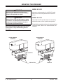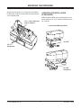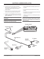
1
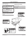
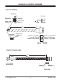
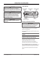
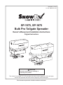
November 1, 2014
Lit. No. 43828, Rev. 00
SP-1575, SP-1875
Bulk Pro Tailgate Spreader
Owner's Manual and Installation Instructions
Original Instructions
CAUTION
Read this manual before installing or
operating the spreader.
This manual is for SnowEx® SP-1575 spreaders with serial numbers beginning 141114 and higher
and SP-1875 spreaders with serial numbers beginning 141112 and higher.
This document supersedes all editions with an earlier date.
TABLE OF CONTENTS
INTRODUCTION.......................................................... 5
OPERATING THE SPREADER................................. 18
Warranty Registration............................................ 5
Cab Control.......................................................... 18
OWNER'S INFORMATION FORM.............................. 5
Starting and Stopping the Motor................... 18
SAFETY INFORMATION.........................................6–9
Adjusting Auger/Spinner Speed.................... 18
LOADING................................................................... 10
Auto-Reverse (AR) Feature........................... 19
Certification.......................................................... 10
Vibrator Function........................................... 19
Determining Vehicle Payload............................... 11
Alarm Codes.................................................. 19
Approximate Material Weights............................. 11
Controlling Flow of Material................................. 19
MOUNTING THE SPREADER.................................. 12
Spreading Tips..................................................... 19
Model SP-1875 .................................................... 12
MAINTENANCE......................................................... 20
Model SP-1575..................................................... 12
Lubrication........................................................... 20
License Plate Installation..................................... 13
After Each Use..................................................... 20
ELECTRICAL HARNESS INSTALLATION............... 14
At the End of Each Season or after
Extended Storage............................................. 20
HARNESS & CONTROL DIAGRAMS...................... 16
Storage................................................................ 20
TROUBLESHOOTING............................................... 21
Lit. No. 43828.00, Rev. 00
3
November 1, 2014
INTRODUCTION
Warranty Registration
This manual has been prepared to acquaint you with
the safety information, operation and maintenance of
your new tailgate spreader. Please read this manual
carefully and follow all recommendations. This will
help ensure profitable and trouble-free operation of
your spreader. Keep this manual accessible. It is a
handy reference in case minor service is required.
Follow the directions on the SnowEx Warranty
Registration and Customer Survey form included in
the spreader literature kit.
The registration form is also available online at
www.snowexproducts.com. Under "Product Info"
select "SnowEx Warranty" and click to download
the form.
When service is necessary, bring your spreader to
your distributor. They know your spreader best and are
interested in your complete satisfaction.
NOTE: This spreader is designed to spread
snow and ice control materials only. Do not use
it for purposes other than those specified in
this manual.
OWNER'S INFORMATION
Owner's Name:_______________________________________________________________________
Date Purchased:______________________________________________________________________
Distributor Name:___________________________________________ Phone:__________________
Distributor Address:____________________________________________________________________
Vehicle Model:______________________________________________ Year:___________________
Spreader Model:__________________________
Serial #:___________________________________
Spreader Weight:______________________lb/kg
Lit. No. 43828.00, Rev. 00
5
November 1, 2014
SAFETY INFORMATION
SAFETY DEFINITIONS
WARNING/CAUTION LABELS
Please become familiar with the Warning and Caution
labels on the spreader.
WARNING
Indicates a potentially hazardous situation
that, if not avoided, could result in death or
serious personal injury.
NOTE: If labels are missing or cannot be read, see
your sales outlet.
CAUTION
Indicates a potentially hazardous situation
that, if not avoided, may result in minor or
moderate injury. It may also be used to alert
against unsafe practices.
SP-1875 spreader only
NOTE: Indicates a situation or action that can lead
to damage to your spreader and vehicle or other
property. Other useful information can also be
described.
ROTATING AUGER CAN CAUSE
SERIOUS INJURY OR DEATH
• Keep arms, hands, and loose clothing
away from auger.
• Shut off control and unplug spreader
before servicing.
D6335
Lit. No. 43828.00, Rev. 00
6
November 1, 2014
SAFETY INFORMATION
SERIAL NUMBER LABEL
Madison Heights, MI 48071 U.S.A.
1-800-725-8377 trynexfactory.com
Model No. SP0000
Serial No. 000000000000SP0000
Manuf. 2014
Madison Heights, MI 48071 U.S.A.
1-800-725-8377 trynexfactory.com
Code
YY
MM
DD
LL
XXXX
ZZZZZZ
Model No. SP0000E
Serial No. YYMMDDLLXXXXZZZZZZ
Manuf. 2014
Lit. No. 43828.00, Rev. 00
7
Definition
2‑Digit Year
2‑Digit Month
2‑Digit Day
2‑Digit Location Code
4‑Digit Sequential Number
Assembly Part Number
November 1, 2014
SAFETY INFORMATION
SAFETY PRECAUTIONS
CAUTION
• Do not operate a spreader in need of
maintenance.
• Before operating the spreader, reassemble
any parts or hardware removed for cleaning
or adjusting.
• Before operating the spreader, remove
materials such as cleaning rags, brushes,
and hand tools from the spreader.
• While operating the spreader, use auxiliary
warning lights, except when prohibited by law.
Improper installation and operation could cause
personal injury and/or equipment and property
damage. Read and understand labels and this
Owner's Manual before installing, operating or
making adjustments.
WARNING
• Driver to keep bystanders minimum of
25 feet away from operating spreader.
• Before working with the spreader, secure all
loose-fitting clothing and unrestrained hair.
• Before operating the spreader, verify that all
safety guards are in place.
• Before servicing the spreader, wait for
auger and spinner to stop.
• Do not climb into or ride on spreader.
CAUTION
Disconnect electric and/or hydraulic power
and tag out if required before servicing or
performing maintenance.
CAUTION
WARNING
Overloading could result in an
accident or damage. Do not exceed
GVWR or GAWR ratings as found
on the driver-side vehicle door
cornerpost. See Loading section to determine
maximum volumes of spreading material.
NOTE: Lubricate grease fittings after each use.
Use a good quality multipurpose grease.
WARNING
PERSONAL SAFETY
Do not install the control for this product in
the deployment path of an air bag. Refer to
vehicle manufacturer's manual for air bag
deployment area(s).
• Remove ignition key and put the vehicle in park or
in gear to prevent others from starting the vehicle
during installation or service.
• Wear only snug-fitting clothing while working on
your vehicle or spreader.
CAUTION
• Do not wear jewelry or a necktie, and secure long
hair.
During the hopper spreader installation
we recommend the addition of an OSHA
compliant Backup Alarm. This alarm is
required for OSHA governed employers.
• Wear safety goggles to protect your eyes from
battery acid, gasoline, dirt and dust.
• Avoid touching hot surfaces such as the engine,
radiator, hoses and exhaust pipes.
CAUTION
If rear directional, CHMSL light or brake
stoplights are obstructed by the spreader,
the lights shall be relocated, or auxiliary
directional or brake stoplights shall be
installed.
Lit. No. 43828.00, Rev. 00
DO NOT leave unused material in
hopper. Material can freeze or solidify,
causing unit to not work properly.
Empty and clean after each use.
• Always have a fire extinguisher rated BC handy,
for flammable liquids and electrical fires.
8
November 1, 2014
SAFETY INFORMATION
FIRE AND EXPLOSION
TORQUE CHART
WARNING
CAUTION
Gasoline is highly flammable and gasoline
vapor is explosive. Never smoke while
working on vehicle. Keep all open flames
away from gasoline tank and lines. Wipe up
any spilled gasoline immediately.
Read instructions before assembling.
Fasteners should be finger tight until
instructed to tighten according to the torque
chart. Use standard methods and practices
when attaching snowplow, including proper
personal protective safety equipment.
Be careful when using gasoline. Do not use gasoline
to clean parts. Store only in approved containers away
from sources of heat or flame.
Recommended Fastener Torque Chart
Inch Fasteners Grade 5 and Grade 8
CELL PHONES
Torque (ft-lb)
Size
A driver's first responsibility is the safe operation of
the vehicle. The most important thing you can do
to prevent a crash is to avoid distractions and pay
attention to the road. Wait until it is safe to operate
Mobile Communication Equipment such as cell phones,
text messaging devices, pagers or two‑way radios.
Grade
5
1/4-20
1/4-28
5/16-18
5/16-24
3/8-16
3/8-24
7/16-14
7/16-20
1/2-13
1/2-20
VENTILATION
8.4
9.7
17.4
19.2
30.8
35.0
49.4
55.2
75.3
85.0
Grade
8
11.9
13.7
24.6
27.3
43.6
49.4
69.8
77.9
106.4
120.0
Size
9/16-12
9/16-18
5/8-11
5/8-18
3/4-10
3/4-16
7/8-9
7/8-14
1-8
1-12
Torque (ft-lb)
Grade
5
109
121
150
170
269
297
429
474
644
704
Grade
8
154
171
212
240
376
420
606
669
909
995
Metric Fasteners Class 8.8 and 10.9
WARNING
Vehicle exhaust contains lethal fumes.
Breathing these fumes, even in low
concentrations, can cause death. Never
operate a vehicle in an enclosed area without
venting exhaust to the outside.
Size
M6 x 1.00
M8 x 1.25
M10 x 1.50
M12 x 1.75
M14 x 2.00
M16 x 2.00
M18 x 2.50
BATTERY SAFETY
Torque (ft-lb)
Class
8.8
7.7
19.5
38.5
67
107
167
222
Class
10.9
11.1
26.9
53.3
93
148
231
318
Size
M20 x 2.50
M22 x 2.50
M24 x 3.00
M27 x 3.00
M30 x 3.50
M33 x 3.50
M36 x 4.00
Torque (ft-lb)
Class
8.8
325
428
562
796
1117
1468
1952
Class
10.9
450
613
778
1139
1545
2101
2701
These torque values apply to fasteners
except those noted in the instructions.
CAUTION
Batteries normally produce explosive gases
which can cause personal injury. Therefore,
do not allow flames, sparks or lit tobacco
to come near the battery. When charging or
working near a battery, always cover your
face and protect your eyes, and also provide
ventilation.
• Batteries contain sulfuric acid which burns
skin, eyes and clothing.
• Disconnect the battery before removing or
replacing any electrical components.
Lit. No. 43828.00, Rev. 00
9
November 1, 2014
LOADING
CERTIFICATION
This Manual covers vehicles that have been
recommended for carrying the tailgate spreader.
Please see your local dealer for proper vehicle
applications.
WARNING
New untitled vehicle installation of a spreader
requires National Highway Traffic Safety
Administration altered vehicle certification
labeling. Installer to verify that struck load of
snow or ice control material does not exceed
GVWR or GAWR rating label and complies
with FMVSS.
WARNING
Overloading could result in an accident or
damage. Do not exceed GVWR or GAWR
as found on the driver-side cornerpost of
vehicle.
CAUTION
Read and adhere to manufacturer's
ice‑control material package
labeling, including Material Safety
Data Sheet requirements.
Lit. No. 43828.00, Rev. 00
10
November 1, 2014
LOADING
DETERMINING VEHICLE PAYLOAD
APPROXIMATE MATERIAL WEIGHTS
Density
(lb/ft3)
Material
WARNING
Overloading could result in an accident or
damage. Do not exceed GVWR or GAWR
ratings as found on the driver-side door
cornerpost of the vehicle. See Loading
Section to determine maximum volumes of
spreading material.
Rock Salt (Dry)
Sand/Salt Mix (Dry)
80–90
95–120
A 1:1 ratio is recommended for salt/sand mix
to prevent material from freezing.
Weight of spreader and mount must be added to
struck material weight to determine total spreader
weight.
1. Install the tailgate spreader and optional
equipment according to the instructions.
WARNING
2. Install or attach any other equipment that will be
on the vehicle while the tailgate spreader will be in
use (step bumper, trailer hitch, snowplows, etc.).
Fill gas tanks.
Do not overload vehicle. Use chart below
to calculate weight of material. Weights of
material are an average for dry materials.
3. Obtain the Gross Vehicle Weight Rating (GVWR),
Front Gross Axle Weight Rating (FGAWR) and
Rear Gross Axle Weight Rating (RGAWR) from
the certification label located inside the driver-side
door jamb or door.
CAUTION
Never use wet materials or materials with
foreign debris with any of these spreaders.
These units are designed to handle dry, clean,
free flowing material.
4. With the occupants in the truck for normal tailgate
spreader operation, weigh the vehicle to obtain
gross vehicle weight (GVW).
5. Subtract the GVW from the GVWR to determine
the available material payload.
6. Obtain the weight per cubic foot (lb/cu ft) of
the desired material. Divide the weight into the
payload to determine the maximum volume of
material that can be carried.
7. Compare the maximum volume to determine the
maximum height of the material in the tailgate
spreader.
8. Fill the hopper with the material to the calculated
height. Reweigh the vehicle with occupants
and verify the GVW, Front Gross Axle Weight
and Rear Gross Axle Weight are less than the
vehicle's ratings.
9. Repeat Steps 6 through 8 for each type of
material.
Lit. No. 43828.00, Rev. 00
11
November 1, 2014
MOUNTING THE SPREADER
MODEL SP-1875
WARNING
Spreader shall be bolted to vehicle frame.
Do not rely on the tie-down chains or straps
alone to hold spreader in vehicle.
Mounts are sold separately for the SP-1875 model.
Refer to the instructions packed with the selected
mount.
MODEL SP-1575
CAUTION
Before lifting, verify that the hopper is empty
of material. The lifting device must be able to
support the spreader's weight as shown in
the spreader specifications table.
The model SP-1575 spreader ships from the factory
with the hitch set up in the 3-point mount position.
To switch the spreader to the truck mount position,
remove the hitch, rotate it 180° as shown below, and
reinstall it.
NOTE: Periodically throughout the snow and ice
control season, verify that mounting devices
are secure.
3-POINT MOUNT
POSITION
TRUCK MOUNT
POSITION
Hitch Pin
Lift Arm Pins
Lit. No. 43828.00, Rev. 00
12
Hitch Pin
November 1, 2014
MOUNTING THE SPREADER
LICENSE PLATE INSTALLATION
(IF REQUIRED)
Always use the longer (1‑1/2") cap screw and washer
to attach the corner of the hitch that fits behind the tab
of the material chute.
Install the license plate to the mounting holes in the
frame using two 1/4" x 1/2" machine screws and two
1/4" locknuts.
1/2" x 1-1/2" Cap Screw
and 1/2" Washer
License Plate Mounting Holes
SP-1575
1/2" x 1"
Cap Screws
SP-1875
(2 Options)
Lit. No. 43828.00, Rev. 00
13
November 1, 2014
ELECTRICAL HARNESS INSTALLATION
1. Route the vehicle harness along the vehicle
frame. Do not route it close to the exhaust system
or engine, where extreme heat could melt the
wiring insulation and short out the spreader and
vehicle electrical systems.
CAUTION
Do not alter, modify or install additional
components in shaded areas shown below.
Failure to comply may interfere with airbag
deployment or cause injury to operator in an
accident.
Attach the harness to frame holes and frame
supports. Do not attach to fuel or brake lines. Use
heavy-duty cable ties or frame clips to fasten the
harness along the frame, and lighter-duty cable
ties everywhere else
2. Mount the rear plug on the vehicle bumper using
supplied fasteners. Locate the plug toward the
center of the bumper, away from the path of debris
thrown by the tires.
5. Connect the harness and the control power cable
to the back of the control and mount the control in
a suitable location within easy reach of the vehicle
operator without restricting access to the vehicle
controls and instrumentation.
NOTE: Apply a small amount of dielectric grease
to the plug. Try to mount the plug facing upward
to help keep plugs tightly sealed.
3. Lay out the control power cable along the fire wall
and fender well. Do not connect the power leads
to the battery yet.
Do not mount the control close to any heater vents
or in areas prohibited by the vehicle manufacturer
for crashworthiness. See the vehicle's body
builder's book, owner's manual or service manual
for details.
4. Drill a new 3/4" hole through the fire wall — or use
an existing access hole — to route the control
power cable and harness into the vehicle cab.
NOTE: You may want to contact the customer
before mounting the control. Some prefer not to
have holes drilled into the dashboard.
CAUTION
Before drilling holes, check to be sure that no
vehicle wiring or other components could be
damaged.
Check the area on the other side of the fire wall to
make sure you will not be drilling into the vehicle
harness or a control module. Generally, either side
of the steering wheel offers a good location.
Lit. No. 43828.00, Rev. 00
14
November 1, 2014
ELECTRICAL HARNESS INSTALLATION
6. Connect the power cable leads to the battery:
Red POSITIVE (+), Black NEGATIVE (–). If using
a dual battery system, always connect to the
primary battery.
• Read lead labels before attaching to power source
or ground.
• No other devices may be spliced into the wiring
harness.
7. Secure loose loom to any other large or medium
vehicle harness using medium-duty cable ties.
• Any repairs to the wiring harness must be done with
heat-shrink butt connectors.
8. Toggle the control POWER switch ON and OFF to
check for power. Once power has been confirmed,
turn the control OFF.
• If adding an in-line fuse, use a 60-amp maxi fuse or
circuit breaker.
NOTE: Use dielectric grease on all electrical
connections.
NOTE: In the off season, remove the control and
put it in a cool, dry place. Vehicle interior summer
temperatures could damage the circuit board and
void the warranty.
NOTE: Do not modify harness length. Any
modifications will void the warranty.
Spreader Control
Control Power Cable
POWER
SPINNER
VIBRATE
AUGER
Vehicle Harness
Spreader
Harness
To Vibrator
To Auger
Motor
Dust Cover
To Spinner
Motor
Connector
Adapter
Lit. No. 43828.00, Rev. 00
15
November 1, 2014
HARNESS & CONTROL DIAGRAMS
VEHICLE HARNESS
End View
Mold Cap
Red
White 10 ga
Spinner (+)
Red 10 ga
Auger (+)
Black 10 ga
Spinner (–)
Green 10 ga
Auger (–)
Black
305"
Blue 12 ga
Vibrator (–)
Orange 10 ga
Vibrator (–)
Spinner (+) 10 ga White
Auger (+) 10 ga Red
Vibrator (+) 12 ga Orange
Hot
Circuit
Spinner (–) 10 ga Black
Auger (–) 10 ga Green
Vibrator (–) 12 ga Blue
Ground
Circuit
CONTROL POWER CABLE
Black
124" Tubing
156"
Red
3/8" Terminals
w/Heat Shrink
Red to
POSITIVE (+)
Black to
NEGATIVE (–)
Front View
Lit. No. 43828.00, Rev. 00
16
November 1, 2014
HARNESS & CONTROL DIAGRAMS
SPREADER HARNESS
Vibrator
2"
Male
Female
52"
BLK
Auger Motor
RED
BLK
Male
Female
RED
Spinner
2"
36"
Spinner (+)
Auger (+)
Vibrator (+)
CONTROL
Vibrator
Black
NEGATIVE (–)
Spinner (–)
Auger (–)
Vibrator (–)
Vibrator
Red
POSITIVE (+)
Auger
Black NEGATIVE (–)
Black
NEGATIVE (–)
Red
POSITIVE (+)
Lit. No. 43828.00, Rev. 00
Auger
Red
POSITIVE (+)
Spinner
Spinner
Red
Black
NEGATIVE (–) POSITIVE (+)
17
November 1, 2014
OPERATING THE SPREADER
CAB CONTROL
WARNING
Never operate equipment when under the
influence of alcohol, drugs, or medications that
might alter your judgment and/or reaction time.
Power ON/OFF
Switch
POWER
WARNING
Auger Speed
Dial
Spinner Speed
Dial
SPINNER
VIBRATE
Never exceed 45 mph (72 km/h) when loaded
spreader is attached to vehicle. Braking
distances may be increased and handling
characteristics may be impaired at speeds
above 45 mph (72 km/h).
AUGER
Vibrator
ON/OFF Switch
WARNING
Never allow children to operate or climb on
equipment.
Display
Starting and Stopping the Motor
WARNING
Before starting the spreader, the driver shall
verify that all bystanders are a minimum of
25 feet away from operating spreader.
To start the spreader, press the control POWER
switch to the ON position.
Press the POWER switch to the OFF position to stop
the spreader.
NOTE: The truck ignition must be ON to start the
spreader.
NOTE: If truck ignition is turned OFF while
spreader is running, the motors will stop.
Adjusting Auger/Spinner Speed
Speed of auger and spinner can be adjusted
separately to get desired flow and spread distance.
Turn the speed dial clockwise to increase speed.
When the POWER switch is set to the ON position, the
spreader will accelerate to the speed set on the dial.
Turn the speed dial counterclockwise to decrease
speed.
Lit. No. 43828.00, Rev. 00
18
November 1, 2014
OPERATING THE SPREADER
Auto-Reverse (AR) Feature
CONTROLLING FLOW OF MATERIAL
If your control displays "OL," this could indicate a
jammed auger. Running the auto reverse (AR) function
can often clear the jam.
The factory installed material baffle in the spreader
stops fine materials from free flowing. When dense
or damp material is being spread, or when more flow
is desired, remove the material baffle. However, it is
recommended that the baffle remain in place when
spreading bulk salt.
1. Press the POWER switch to the OFF position and
leave the control OFF for 3 seconds.
2. Press the POWER switch to the ON position.
The inverted vee in the SP-1875 spreader should not
be removed except when servicing the spreader.
When the machine restarts, the AR sequence will
begin automatically, and the auger will reverse for
several rotations to clear the jam. After a pause
of several moments, the auger will automatically
return to normal rotation.
The Material Control Tube optional accessory
prevents leaking issues when handling fine pellet and
flake materials.
SPREADING TIPS
3. If the jam was not cleared, the control will again
display "OL." You may repeat Steps 1 & 2 for a
second and third time.
• Spread ice melters with the storm to prevent
unmanageable levels of ice.
• Never exceed 10 mph (16 km/h) when spreading.
CAUTION
Disconnect electric power and tag out if
required before servicing or performing
maintenance.
• For a wider pass, increase spinner speed.
• For a heavier pass, drive slower or increase
auger speed.
4. If, after the third try, the control still displays "OL,"
you must extract the material that is causing the
problem.
• Never operate spreader near pedestrians.
• Calculate spread pattern when near vegetation.
Follow all warning directions when clearing jams.
NOTE: The spinner motor is not designed for
continuous duty. Allow the motor to cool between
long cycle times.
Vibrator Function
A heavy-duty vibrator is standard equipment on the
Model SP-1575 and SP-1875 spreaders. Turn the
vibrator ON as needed to keep dense material flowing
and prevent bridging of material in the hopper.
Alarm Codes
If the control emits beeping sounds, check the display
for problem codes and follow the instructions given in
the Troubleshooting section of this manual.
Refer to the Troubleshooting section if any problems
occur while operating the spreader.
Lit. No. 43828.00, Rev. 00
19
November 1, 2014
MAINTENANCE
AFTER EACH USE
WARNING
Never remove the spreader with material in
the hopper.
CAUTION
DO NOT leave unused material in
hopper. Material can freeze or solidify,
causing unit to not work properly.
Empty and clean after each use.
CAUTION
Disconnect electric power at spreader
electrical wiring harness connection and tag
out if required before servicing or performing
maintenance.
• Wash out the hopper and rinse off all external
surfaces.
• Apply dielectric grease on all electrical
connections to prevent corrosion.
CAUTION
• When replacing parts use only original
manufacturer's parts. Failure to do so will
void warranty.
• The control is a solid-state electronic unit
and is not serviceable. Any attempt to
service will void warranty.
• There are no serviceable parts in the motor/
transmission assembly. Any attempt to
service will void warranty.
• When pressure washing motor enclosure
area, stay at least 36" away from motor
enclosures.
AT THE END OF EACH SEASON
OR AFTER EXTENDED STORAGE
• Wash out the hopper and rinse off all external
surfaces.
• Apply dielectric grease on all electrical
connections to prevent corrosion.
• Lubricate all grease fittings with good quality
multipurpose grease.
• Oil or paint all bare metal surfaces.
LUBRICATION
• If motor cover is removed for any reason, use
silicone sealant to ensure weather proofing of
enclosure.
To keep your spreader running smoothly, observe the
following recommendations:
• Lubricate bearings after every 20 hours of use.
STORAGE
• Apply a small amount of light oil to latches as
needed.
Store the spreader in a clean, dry location and away
from direct sunlight.
• For SP-1875 spreader installations using the pivot
mount, keep the pivot assembly well greased to
prevent corrosion.
Lit. No. 43828.00, Rev. 00
NOTE: In the off season, remove the control and
put it in a cool, dry place. Vehicle interior summer
temperatures could damage the circuit board and
void the warranty.
20
November 1, 2014
TROUBLESHOOTING
Please see your SnowEx distributor for service. The troubleshooting reference table below and the diagrams on
the following pages may also guide you in diagnosing the issue.
Before servicing the spreader:
• Review all safety information.
• Confirm that all electrical connections are tight and clean.
• Confirm that nothing is jammed in the hopper.
ISSUE
Motor doesn't run.
POSSIBLE CAUSE
POSSIBLE SOLUTION
Loose electrical connections
Check all connections.
Blown fuse
Replace fuse.
Motor seized
Replace motor.
Jammed auger
Carefully clear jammed material.
Poor electrical conditions
Clean or replace connectors. Apply
dielectric grease.
Electrical short
Check electrical connections.
Check for bare wires.
Control failure
Replace control.
Empty hopper
Fill hopper.
Wet material
Replace with dry material.
Frozen or coarse material
Replace material.
Spinner not turning
Check connection inside motor
enclosure.
Auger loose on shaft
Align auger with flat machined area
on shaft and tighten locking bolt on
side of auger.
Vibrator not working
Check electrical connection; if
connection is confirmed, replace
vibrator.
Alarm beeps, display shows "OL"
or "OH."
Jammed auger, overload
shutdown
Turn spreader OFF for 3 seconds,
then restart. If alarm continues, turn
spreader OFF and clear lumps and
debris from around auger.
Alarm beeps, display shows "E1."
System short
Turn spreader OFF. Do not use
spreader until problem is corrected.
Alarm beeps, display shows "EO."
No power to motor
Turn spreader OFF.
Check all electrical connections.
Alarm beeps, display shows "LB."
Vehicle battery is extremely
low; poor battery connection.
Turn spreader OFF.
Check battery connection. Charge
vehicle battery.
Control shuts down.
Material does not flow from
hopper.
Lit. No. 43828.00, Rev. 00
21
November 1, 2014
TROUBLESHOOTING
Spreader
does not run.
Control turns on,
beeps, shuts off,
displays error code.
OL code
Definition:
Amp draw too high
Jammed material
Switch OFF & ON
for auto-reverse
function.
Bad motor;
contact distributor.
4- to 20-amp draw,
no load — good
Clear jam.
20+ amp draw,
no load — bad
Bad transmission;
contact distributor.
Turn shaft by hand;
should turn freely.
Corrosion
Replace all
corroded
connections.
Apply dielectric
grease.
Bad control;
contact distributor.
EO code
LB code
Definition:
Open circuit
between motor
and control
Definition:
Bad electrical
connection
Spreader
unplugged
Plug in spreader.
Motor power cord
disconnected
inside enclosure.
Open access cover
and plug together.
Break in wiring
harness; contact
distributor.
Replace harness.
Corrosion
Replace all
corroded
connections.
Loose connection,
bad ground
Tighten or replace
Definition:
Low battery, less
than 12V output
Load test battery.
E1 code
Definition:
Dead short in
motor circuit
Replace affected
components.
All other codes
Check harness
for spliced-in
accessory.
Bad control;
contact distributor.
ON/OFF switch
lights no display
Check input power.
Bad control;
contact distributor.
Nothing happens,
no display, ON/OFF
will not light up
Check power
source to control.
Bad control;
contact distributor.
Lit. No. 43828.00, Rev. 00
22
November 1, 2014
TROUBLESHOOTING
Material Flow Troubleshooting
Material free flows.
Material does not
flow.
Material
flows too slowly.
Check baffle
length.
18" correct length
Material issue
Check baffle
position.
Should touch
hopper on 3 sides.
Material issue
Material
obstruction
Remove
obstruction.
Material issue
Auger runs
backward.
Run 12V to auger
circuit on spreader
power cord.
Auger runs
proper direction.
Replace vehicle
harness.
Auger runs
backward.
Check connections
at auger motor for
reverse polarity.
Turn on vibrator.
Polarity correct;
replace spreader
harness.
Turn on vibrator.
Increase auger
speed.
Material issue
Lit. No. 43828.00, Rev. 00
23
November 1, 2014
531 Ajax Drive
Madison Heights, MI 48071‑2429
www.snowexproducts.com
A DIVISION OF DOUGLAS DYNAMICS, LLC
TrynEx International reserves the right under its product improvement policy to change construction or design details and furnish equipment
when so altered without reference to illustrations or specifications used. TrynEx International or the vehicle manufacturer may require or
recommend optional equipment for spreaders. Do not exceed vehicle ratings with a spreader. TrynEx International offers a limited warranty for
all spreaders and accessories. See separately printed page for this important information. The following are registered (®) or unregistered (™)
trademarks of Douglas Dynamics, LLC: SnowEx ®, TrynEx ®.
Printed in U.S.A.
Lit. No. 43759, Rev. 00
November 1, 2014