1
SPARC T4-1B Server Module
Service Manual
Part No.: E22739-05
November 2012
Copyright © 2011, 2012, Oracle and/or its affiliates. All rights reserved.
This software and related documentation are provided under a license agreement containing restrictions on use and disclosure and are protected by
intellectual property laws. Except as expressly permitted in your license agreement or allowed by law, you may not use, copy, reproduce, translate,
broadcast, modify, license, transmit, distribute, exhibit, perform, publish, or display any part, in any form, or by any means. Reverse engineering,
disassembly, or decompilation of this software, unless required by law for interoperability, is prohibited.
The information contained herein is subject to change without notice and is not warranted to be error-free. If you find any errors, please report them to us
in writing.
If this is software or related software documentation that is delivered to the U.S. Government or anyone licensing it on behalf of the U.S. Government, the
following notice is applicable:
U.S. GOVERNMENT END USERS. Oracle programs, including any operating system, integrated software, any programs installed on the hardware,
and/or documentation, delivered to U.S. Government end users are "commercial computer software" pursuant to the applicable Federal Acquisition
Regulation and agency-specific supplemental regulations. As such, use, duplication, disclosure, modification, and adaptation of the programs, including
any operating system, integrated software, any programs installed on the hardware, and/or documentation, shall be subject to license terms and license
restrictions applicable to the programs. No other rights are granted to the U.S. Government.
This software or hardware is developed for general use in a variety of information management applications. It is not developed or intended for use in any
inherently dangerous applications, including applications which may create a risk of personal injury. If you use this software or hardware in dangerous
applications, then you shall be responsible to take all appropriate fail-safe, backup, redundancy, and other measures to ensure its safe use. Oracle
Corporation and its affiliates disclaim any liability for any damages caused by use of this software or hardware in dangerous applications.
Oracle and Java are registered trademarks of Oracle and/or its affiliates. Other names may be trademarks of their respective owners.
Intel and Intel Xeon are trademarks or registered trademarks of Intel Corporation. All SPARC trademarks are used under license and are trademarks or
registered trademarks of SPARC International, Inc. AMD, Opteron, the AMD logo, and the AMD Opteron logo are trademarks or registered trademarks of
Advanced Micro Devices. UNIX is a registered trademark of The Open Group.
This software or hardware and documentation may provide access to or information on content, products, and services from third parties. Oracle
Corporation and its affiliates are not responsible for and expressly disclaim all warranties of any kind with respect to third-party content, products, and
services. Oracle Corporation and its affiliates will not be responsible for any loss, costs, or damages incurred due to your access to or use of third-party
content, products, or services.
Copyright © 2011, 2012, Oracle et/ou ses affiliés. Tous droits réservés.
Ce logiciel et la documentation qui l’accompagne sont protégés par les lois sur la propriété intellectuelle. Ils sont concédés sous licence et soumis à des
restrictions d’utilisation et de divulgation. Sauf disposition de votre contrat de licence ou de la loi, vous ne pouvez pas copier, reproduire, traduire,
diffuser, modifier, breveter, transmettre, distribuer, exposer, exécuter, publier ou afficher le logiciel, même partiellement, sous quelque forme et par
quelque procédé que ce soit. Par ailleurs, il est interdit de procéder à toute ingénierie inverse du logiciel, de le désassembler ou de le décompiler, excepté à
des fins d’interopérabilité avec des logiciels tiers ou tel que prescrit par la loi.
Les informations fournies dans ce document sont susceptibles de modification sans préavis. Par ailleurs, Oracle Corporation ne garantit pas qu’elles
soient exemptes d’erreurs et vous invite, le cas échéant, à lui en faire part par écrit.
Si ce logiciel, ou la documentation qui l’accompagne, est concédé sous licence au Gouvernement des Etats-Unis, ou à toute entité qui délivre la licence de
ce logiciel ou l’utilise pour le compte du Gouvernement des Etats-Unis, la notice suivante s’applique :
U.S. GOVERNMENT END USERS. Oracle programs, including any operating system, integrated software, any programs installed on the hardware,
and/or documentation, delivered to U.S. Government end users are "commercial computer software" pursuant to the applicable Federal Acquisition
Regulation and agency-specific supplemental regulations. As such, use, duplication, disclosure, modification, and adaptation of the programs, including
any operating system, integrated software, any programs installed on the hardware, and/or documentation, shall be subject to license terms and license
restrictions applicable to the programs. No other rights are granted to the U.S. Government.
Ce logiciel ou matériel a été développé pour un usage général dans le cadre d’applications de gestion des informations. Ce logiciel ou matériel n’est pas
conçu ni n’est destiné à être utilisé dans des applications à risque, notamment dans des applications pouvant causer des dommages corporels. Si vous
utilisez ce logiciel ou matériel dans le cadre d’applications dangereuses, il est de votre responsabilité de prendre toutes les mesures de secours, de
sauvegarde, de redondance et autres mesures nécessaires à son utilisation dans des conditions optimales de sécurité. Oracle Corporation et ses affiliés
déclinent toute responsabilité quant aux dommages causés par l’utilisation de ce logiciel ou matériel pour ce type d’applications.
Oracle et Java sont des marques déposées d’Oracle Corporation et/ou de ses affiliés.Tout autre nom mentionné peut correspondre à des marques
appartenant à d’autres propriétaires qu’Oracle.
Intel et Intel Xeon sont des marques ou des marques déposées d’Intel Corporation. Toutes les marques SPARC sont utilisées sous licence et sont des
marques ou des marques déposées de SPARC International, Inc. AMD, Opteron, le logo AMD et le logo AMD Opteron sont des marques ou des marques
déposées d’Advanced Micro Devices. UNIX est une marque déposée d’The Open Group.
Ce logiciel ou matériel et la documentation qui l’accompagne peuvent fournir des informations ou des liens donnant accès à des contenus, des produits et
des services émanant de tiers. Oracle Corporation et ses affiliés déclinent toute responsabilité ou garantie expresse quant aux contenus, produits ou
services émanant de tiers. En aucun cas, Oracle Corporation et ses affiliés ne sauraient être tenus pour responsables des pertes subies, des coûts
occasionnés ou des dommages causés par l’accès à des contenus, produits ou services tiers, ou à leur utilisation.
Please
Recycle
Contents
Using This Documentation
Identifying Components
ix
1
Illustrated Parts Breakdown
1
Front and Rear Panel Components
Detecting and Managing Faults
Diagnostics Overview
Diagnostics Process
Diagnostics LEDs
3
5
5
7
10
Managing Faults (Oracle ILOM)
11
Oracle ILOM Troubleshooting Overview
Fault Management
Fault Clearing
12
12
13
Oracle Solaris Fault Manager Commands in Oracle ILOM
Drive Faults
14
14
▼
Access the SP (Oracle ILOM)
▼
Display FRU Information (show Command)
17
▼
Check for Faults (show faulty Command)
18
▼
Check for Faults (fmadm faulty Command)
▼
Clear Faults (clear_fault_action Property)
15
Service-Related Oracle ILOM Commands
Interpreting Log Files and System Messages
20
21
22
23
iii
▼
Check the Message Buffer (dmesg Command)
▼
View System Message Log Files
▼
List FRU Status (prtdiag Command)
24
24
25
Checking if Oracle VTS Software Is
Installed 27
Oracle VTS Overview
▼
28
Check if Oracle VTS Software Is Installed
Managing Faults (POST)
POST Overview
28
29
30
Oracle ILOM Properties That Affect POST Behavior
▼
Configure POST
▼
Run POST With Maximum Testing
▼
Interpret POST Fault Messages
▼
Clear POST-Detected Faults
33
POST Output Reference
Managing Faults (PSH)
PSH Overview
39
41
41
Check for PSH-Detected Faults
▼
Clear PSH-Detected Faults
Managing Components (ASR)
42
44
45
46
▼
Display System Components
47
▼
Disable System Components
48
▼
Enable System Components
Preparing for Service
51
Safety Information
51
Safety Symbols
52
ESD Measures
iv
37
▼
ASR Overview
37
52
SPARC T4-1B Server Module Service Manual • November 2012
49
35
30
Antistatic Wrist Strap Use
Antistatic Mat
53
53
Handling Precautions
53
Tools Needed for Service
54
▼
Find the Modular System Chassis Serial Number
▼
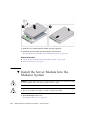
Find the Server Module Serial Number
▼
Locate the Server Module
54
55
56
Preparing the Server Module for Removal
56
▼
Shut Down the OS and Host (Commands)
▼
Shut Down the OS and Host (Power Button – Graceful)
▼
Shut Down the OS and Host (Emergency Shutdown)
▼
Set the Server Module to a Ready-to-Remove State
60
▼
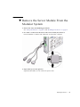
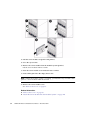
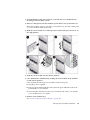
Remove the Server Module From the Modular System
61
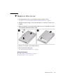
▼
Remove the Cover
Servicing Drives
59
59
63
65
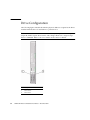
Drive Configuration
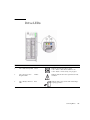
Drive LEDs
57
66
67
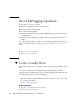
Drive Hot-Plugging Guidelines
▼
Locate a Faulty Drive
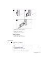
▼
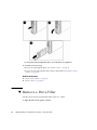
Remove a Drive
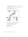
▼
Remove a Drive Filler
▼
Install a Drive
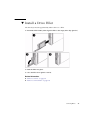
▼
Install a Drive Filler
▼
Verify Drive Functionality
68
69
70
71
Servicing Memory
75
Memory Faults
75
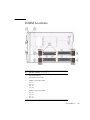
DIMM Locations
68
73
74
77
Contents
v
DIMM Configuration Guidelines
DIMM Handling Precautions
80
▼
Locate a Faulty DIMM
▼
Remove a DIMM
▼
Install a DIMM
▼
Clear the Fault and Verify the Functionality of the Replacement DIMM
▼
Verify DIMM Functionality
Servicing the REM
80
81
82
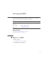
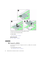
Remove a REM
▼
Install a REM
91
92
95
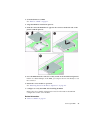
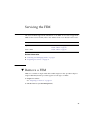
▼
Remove a FEM
▼
Install a FEM
95
96
Servicing the SP Card
99
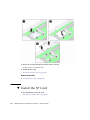
▼
Remove the SP Card
▼
Install the SP Card
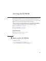
Servicing the ID PROM
99
100
103
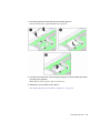
▼
Remove the ID PROM
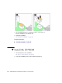
▼
Install the ID PROM
104
▼
Verify the ID PROM
105
Servicing a USB Flash Drive
103
107
▼
Remove a USB Flash Drive
▼
Install a USB Flash Drive
Servicing the Battery
▼
87
91
▼
Servicing the FEM
vi
79
107
108
111
Replace the Battery
111
SPARC T4-1B Server Module Service Manual • November 2012
84
Replacing the Server Module Enclosure Assembly (Motherboard)
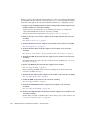
▼
Transfer Components to Another Enclosure Assembly
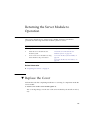
Returning the Server Module to Operation
Replace the Cover
▼
Install the Server Module Into the Modular System
▼
Power On the Host (Oracle ILOM)
122
▼
Power On the Host (Power Button)
122
Index
115
119
▼
Glossary
115
119
120
125
131
Contents
vii
viii
SPARC T4-1B Server Module Service Manual • November 2012
Using This Documentation
This service manual explains how to identify faults, replace parts, and add additional
options in Oracle’s SPARC T4-1B server module.
This document is written for technicians, system administrators, authorized service
providers, and users who have experience troubleshooting and replacing hardware.
■
“Related Documentation” on page ix
■
“Feedback” on page x
■
“Support and Accessibility” on page x
Related Documentation
Documentation
Links
All Oracle products
http://www.oracle.com/documentation
SPARC T4-1B server
module
http://www.oracle.com/pls/topic/lookup?ctx=SPARCT4-1B
Sun Blade 6000 modular
system
http://www.oracle.com/pls/topic/lookup?ctx=E19938-01
Oracle Integrated Lights
Out Manager (Oracle
ILOM)
http://www.oracle.com/pls/topic/lookup?ctx=ilom30
ix
Documentation
Links
Oracle Solaris OS and
other system software
http://www.oracle.com/technetwork/indexes/documentation/#sys_sw
Oracle VTS software
http://www.oracle.com/pls/topic/lookup?ctx=OracleVTS7.0
SAS-1/SAS-2
Compatibility
http://www.oracle.com/pls/topic/lookup?ctx=E22513_01
Feedback
Provide feedback on this documentation at:
http://www.oracle.com/goto/docfeedback
Support and Accessibility
Description
Links
Access electronic support
through My Oracle Support
http://support.oracle.com
For hearing impaired:
http://www.oracle.com/accessibility/support.html
Learn about Oracle’s
commitment to accessibility
x
http://www.oracle.com/us/corporate/accessibility/index.html
SPARC T4-1B Server Module Service Manual • November 2012
Identifying Components
These topics explain the components of the server module, focusing on the
components that can be removed and replaced for service.
■
“Illustrated Parts Breakdown” on page 1
■
“Front and Rear Panel Components” on page 3
Related Information
■
“Detecting and Managing Faults” on page 5
■
“Replacing the Server Module Enclosure Assembly (Motherboard)” on page 115
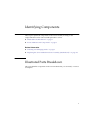
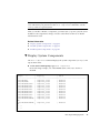
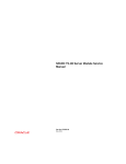
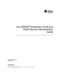
Illustrated Parts Breakdown
This topic identifies components in the server module that you can install, or remove
and replace.
1
No. FRU
FRU Name (If Applicable)
Links
1
DIMMs
/SYS/MB/CMP0/BOBn/CHn/Dn
“Servicing Memory” on page 75
2
Rear connector cover
3
ID PROM
4
USB flash drive
5
Clock battery
/SYS/MB/BAT
“Servicing the Battery” on page 111
6
Drive (HD or SSD)
/SYS/HDDn
“Servicing Drives” on page 65
7
Drive filler
8
Enclosure assembly
/SYS/MB
“Replacing the Server Module Enclosure Assembly
(Motherboard)” on page 115
9
SP
/SYS/MB/SP
“Servicing the SP Card” on page 99
10
REM
/SYS/MB/REM
“Servicing the REM” on page 91
11
FEM
/SYS/MB/FEM
“Servicing the FEM” on page 95
2
Remove before inserting the server module in a slot.
/SYS/MB/SCC
“Servicing the ID PROM” on page 103
“Servicing a USB Flash Drive” on page 107
“Servicing Drives” on page 65
SPARC T4-1B Server Module Service Manual • November 2012
Related Information
■
“Front and Rear Panel Components” on page 3
■
“Detecting and Managing Faults” on page 5
■
“Replacing the Server Module Enclosure Assembly (Motherboard)” on page 115
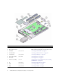
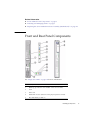
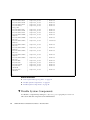
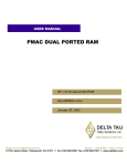
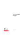
Front and Rear Panel Components
See “Diagnostics LEDs” on page 10 for more information.
No.
Description
1
RFID tag (provides the serial number of the server module)
2
UCP
3
Drive slots
4
White LED: Locator (functions as the physical presence switch)
5
Blue LED: Ready to Remove
Identifying Components
3
No.
Description
6
Amber LED: Fault (Service Action Required)
7
Green LED: OK
8
Power button
9
Reset button: NMI (for service use only)
10
Green LED: Drive OK
11
Amber LED: Drive Fault (Service Action Required)
12
Blue LED: Drive Ready to Remove
13
Rear chassis power connector
14
Rear chassis data connection
Related Information
4
■
“Diagnostics LEDs” on page 10
■
“Illustrated Parts Breakdown” on page 1
SPARC T4-1B Server Module Service Manual • November 2012
Detecting and Managing Faults
These topics explain how to use various diagnostic tools to monitor server module
status and troubleshoot faults in the server module.
■
“Diagnostics Overview” on page 5
■
“Diagnostics Process” on page 7
■
“Diagnostics LEDs” on page 10
■
“Managing Faults (Oracle ILOM)” on page 11
■
“Interpreting Log Files and System Messages” on page 23
■
“Checking if Oracle VTS Software Is Installed” on page 27
■
“Managing Faults (POST)” on page 29
■
“Managing Faults (PSH)” on page 41
■
“Managing Components (ASR)” on page 45
Related Information
■
“Preparing for Service” on page 51
Diagnostics Overview
You can use a variety of diagnostic tools, commands, and indicators to monitor and
troubleshoot a server module:
■
LEDs – Provide a quick visual notification of the status of the server module and
of some of the FRUs.
■
Oracle ILOM – This firmware runs on the SP. In addition to providing the
interface between the hardware and OS, Oracle ILOM also tracks and reports the
health of key server module components. Oracle ILOM works closely with POST
and PSH technology to keep the server module running even when there is a
faulty component. You can log in to multiple SP accounts simultaneously and
have separate Oracle ILOM shell commands executing concurrently under each
account.
5
Note – Unless indicated otherwise, all examples of interaction with the SP are
depicted with Oracle ILOM shell commands.
■
POST – Performs diagnostics on server module components upon reset to ensure
the integrity of those components. POST can be configured and works with Oracle
ILOM to take faulty components offline if needed.
■
PSH – This Oracle Solaris OS technology continuously monitors the health of the
CPU, memory, and other components, and works with Oracle ILOM to take a
faulty component offline if needed. The PSH technology enables server modules to
accurately predict component failures and mitigate many serious problems before
they occur.
■
Log files and command interface – Provide the standard Oracle Solaris OS log
files and investigative commands that can be accessed and displayed on the
device of your choice.
■
Oracle VTS (formerly SunVTS) – An application that exercises the server
module, provides hardware validation, and discloses possible faulty components
with recommendations for repair.
The LEDs, Oracle ILOM, PSH, and many of the log files and console messages are
integrated. For example, when the Oracle Solaris OS detects a fault, it displays the
fault, logs it, and passes information to Oracle ILOM, where it is logged. Depending
on the fault, one or more LEDs might also be illuminated.
The diagnostic flowchart in “Diagnostics Process” on page 7 illustrates an approach
for using the server module diagnostics to identify a faulty FRU. The diagnostics you
use, and the order in which you use them, depend on the nature of the problem you
are troubleshooting. Therefore, you might perform some actions and not others.
Related Information
6
■
Server Module Administration Guide
■
“Diagnostics Process” on page 7
■
“Diagnostics LEDs” on page 10
■
“Managing Faults (Oracle ILOM)” on page 11
■
“Interpreting Log Files and System Messages” on page 23
■
“Managing Faults (PSH)” on page 41
■
“Managing Faults (POST)” on page 29
■
“Managing Components (ASR)” on page 45
■
“Checking if Oracle VTS Software Is Installed” on page 27
SPARC T4-1B Server Module Service Manual • November 2012
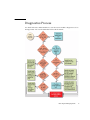
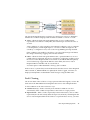
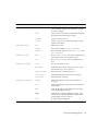
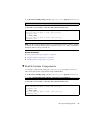
Diagnostics Process
Use the flowchart to understand how to use the server module’s diagnostic tools to
manage faults. Also see the table that follows this flowchart.
Detecting and Managing Faults
7
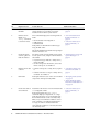
Flowchart
No.
Diagnostic Action
Possible Outcome
1.
Check the Power
OK LED.
If this LED is not lit, check the power source and • “Diagnostics LEDs” on
ensure that the server module is properly
page 10
installed in the modular system chassis.
2.
Run the Oracle
ILOM show
faulty command
to check for faults.
This command displays the following kinds of
faults:
• Environmental and configuration
• PSH-detected
• POST-detected
Faulty FRUs are identified in fault messages
using the FRU name.
All Oracle ILOM detected fault messages begin
with the characters SPT.
• “Service-Related Oracle
ILOM Commands” on
page 22
• “Check for Faults (show
faulty Command)” on
page 18
3.
Check the Oracle
Solaris log files for
fault information.
The Oracle Solaris message buffer and log files
record system events, and provide information
about faults.
• If system messages indicate a faulty device,
replace the FRU.
• For more diagnostic information, review the
Oracle VTS report. See number 4.
• “Interpreting Log Files and
System Messages” on
page 23
4.
Run the Oracle VTS
software.
• If Oracle VTS reports a faulty device, replace
it.
• If Oracle VTS does not report a faulty device,
run POST. See number 5.
• “Checking if Oracle VTS
Software Is Installed” on
page 27
5.
Run POST.
POST performs basic tests of the server module
components and reports faulty FRUs.
• “Managing Faults (POST)”
on page 29
• “Oracle ILOM Properties
That Affect POST Behavior”
on page 30
6.
Check if the fault is
environmental.
Determine if the fault is an environmental fault
or a configuration fault.
If the fault listed by the show faulty
command displays a temperature or voltage
fault, then the fault is an environmental fault.
Environmental faults can be caused by faulty
FRUs, or by environmental conditions such as
when computer room ambient temperature is
too high, or airflow is blocked. When the
environmental condition is corrected, the fault
automatically clears.
• “Check for Faults (show
faulty Command)” on
page 18
8
SPARC T4-1B Server Module Service Manual • November 2012
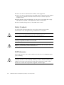
Additional Information
Flowchart
No.
Diagnostic Action
Possible Outcome
Additional Information
7.
Determine if the
fault was detected
by PSH.
If the fault message does not begin with the
characters SPT, the fault was detected by the
PSH feature.
After the FRU is replaced, perform the
procedure to clear PSH detected faults.
• “Managing Faults (PSH)” on
page 41
• “Clear PSH-Detected
Faults” on page 44
8.
Determine if the
fault was detected
by POST.
POST performs basic tests of the server module • “Managing Faults (POST)”
components and reports faulty FRUs. When
on page 29
POST detects a faulty FRU, POST logs the fault • “Clear POST-Detected
and if possible, takes the FRU offline. POST
Faults” on page 37
detected FRUs display the following text in the • “POST Output Reference”
fault message:
on page 39
Forced fail reason
where reason is the name of the power-on routine
that detected the failure.
9.
Contact technical
support.
The majority of hardware faults are detected by • “Support and Accessibility”
the server module’s diagnostics. In rare cases a
on page x
problem might require additional
troubleshooting. If you are unable to determine
the cause of the problem, contact Oracle Support
or go to: http://support.oracle.com
Related Information
■
Server Module Administration Guide
■
“Diagnostics Overview” on page 5
■
“Diagnostics LEDs” on page 10
■
“Managing Faults (Oracle ILOM)” on page 11
■
“Interpreting Log Files and System Messages” on page 23
■
“Managing Faults (PSH)” on page 41
■
“Managing Faults (POST)” on page 29
■
“Managing Components (ASR)” on page 45
■
“Checking if Oracle VTS Software Is Installed” on page 27
Detecting and Managing Faults
9
Diagnostics LEDs
The server module has LEDs on the front panel and on the drives. The LEDs conform
to ANSI SIS. For the locations of these LEDs, see “Front and Rear Panel
Components” on page 3, and “Drive LEDs” on page 67.
LED or Button
Color
Description
Locator LED
and button
White
You can turn on the Locator LED to identify a particular server
module. When on, the LED blinks rapidly. There are two methods
for turning a Locator LED on:
• Issuing the Oracle ILOM command set /SYS/LOCATE
value=Fast_Blink.
• Pressing the Locator button.
The Locator LED functions as the physical presence switch.
Ready to
Remove LED
Blue
Steady state – If LED is off, it is not safe to remove the server
module from the modular system chassis. You must use Oracle
ILOM to shut down the server module and put the blade into
ready to remove state before this LED is on.
Service Action
Required LED
Amber
Indicates that service is required. POST and Oracle ILOM are two
diagnostics tools that can detect a fault or failure resulting in this
indication. Also, faults detected by PSH can result in Oracle
ILOM lighting this LED.
The Oracle ILOM show faulty command provides details about
any faults that cause this indicator to light.
Under some fault conditions, individual component fault LEDs
are turned on in addition to the Service Action Required LED.
Power OK LED
Green
Indicates the following conditions:
• Off – Host is not running in its normal state. Host power might
be off. The SP might be running.
• Steady on – Host is powered on and is running in its normal
operating state. No service actions are required.
• Fast blink – Host is running in standby mode and can be
quickly returned to full function.
• Slow blink – A normal, but transitory activity is taking place.
Slow blinking might indicate that diagnostics are running, or
the host is booting.
10
Icon or Label
SPARC T4-1B Server Module Service Manual • November 2012
LED or Button
Icon or Label
Color
Description
On/Standby
button
n/a
The recessed Power button toggles the host on or off.
• Press once to turn the host on.
• Press once to shut the host down to a standby state.
• Press and hold for 4 seconds to perform an emergency
shutdown.
Drive Ready to
Remove LED
Blue
Indicates that the drive can be removed during a hot-plug
operation.
Drive Service
Action
Required LED
Amber
Indicates that the drive has experienced a fault condition.
Drive
OK/Activity
LED
Green
Indicates the following drive status:
• On – Drive is idle and available for use.
• Off – Read or write activity is in progress.
Related Information
■
“Diagnostics Overview” on page 5
■
“Diagnostics Process” on page 7
■
“Managing Faults (Oracle ILOM)” on page 11
■
“Interpreting Log Files and System Messages” on page 23
■
“Managing Faults (PSH)” on page 41
■
“Managing Faults (POST)” on page 29
■
“Managing Components (ASR)” on page 45
■
“Checking if Oracle VTS Software Is Installed” on page 27
Managing Faults (Oracle ILOM)
These topics explain how to use Oracle ILOM, the SP firmware, to diagnose faults
and verify successful repairs.
■
“Oracle ILOM Troubleshooting Overview” on page 12
■
“Access the SP (Oracle ILOM)” on page 15
■
“Display FRU Information (show Command)” on page 17
Detecting and Managing Faults
11
■
“Check for Faults (show faulty Command)” on page 18
■
“Check for Faults (fmadm faulty Command)” on page 20
■
“Clear Faults (clear_fault_action Property)” on page 21
■
“Service-Related Oracle ILOM Commands” on page 22
■
“Oracle ILOM Properties That Affect POST Behavior” on page 30
Related Information
■
“Diagnostics Overview” on page 5
■
“Diagnostics Process” on page 7
■
“Interpreting Log Files and System Messages” on page 23
■
“Managing Faults (PSH)” on page 41
■
“Managing Faults (POST)” on page 29
■
“Managing Components (ASR)” on page 45
■
“Checking if Oracle VTS Software Is Installed” on page 27
■
“POST Overview” on page 30
■
“Oracle ILOM Properties That Affect POST Behavior” on page 30
Oracle ILOM Troubleshooting Overview
Oracle ILOM enables you to remotely run diagnostics, such as POST, that would
otherwise require physical proximity to the server module. You can also configure
Oracle ILOM to send email alerts of hardware failures, hardware warnings, and other
events related to the server module or Oracle ILOM.
The SP runs independently of the server module, using the server module’s standby
power. Therefore, Oracle ILOM continues to function when the server module OS
goes offline or when the server module is powered off.
Fault Management
Error conditions detected by Oracle ILOM, POST, and PSH are forwarded to Oracle
ILOM for fault handling.
12
SPARC T4-1B Server Module Service Manual • November 2012
The Oracle ILOM fault manager evaluates error messages it receives to determine
whether the condition being reported should be classified as an alert or a fault.
■
Alerts – When the fault manager determines that an error condition being
reported does not indicate a faulty FRU, the fault manager classifies the error as
an alert.
Alert conditions are often caused by environmental conditions, such as computer
room temperature, which might improve over time. Conditions might also be
caused by a configuration error, such as the wrong DIMM type being installed.
If the conditions responsible for the alert go away, the fault manager will detect
the change and will stop logging alerts for that condition.
■
Faults – When the fault manager determines that a particular FRU has an error
condition that is permanent, that error is classified as a fault. This condition causes
the Service Action Required LEDs to be turned on, the FRUID PROMs updated,
and a fault message logged. If the FRU has status LEDs, the Service Action
Required LED for that FRU will also be turned on.
You must replace a FRU identified as having a fault condition.
In the event of a system fault, Oracle ILOM ensures that the Service Action Required
LED is turned on, FRUID PROMs are updated, the fault is logged, and alerts are
displayed. Faulty FRUs are identified in fault messages using the FRU name.
Fault Clearing
The SP can detect when a fault is no longer present. When this happens, it clears the
fault state in the FRU PROM and extinguishes the Service Action Required LED.
A fault condition can be removed in two ways:
■
Unaided recovery – Faults caused by environmental conditions can clear
automatically if the condition responsible for the fault is no longer present.
■
Repaired fault – When a fault is repaired by human intervention, such as a FRU
replacement, the SP will usually detect the repair automatically and extinguish the
Service Action Required LED. If the SP does not perform these actions, you must
Detecting and Managing Faults
13
perform these tasks manually by setting the Oracle ILOM component_state or
fault_state of the faulted component. The procedure for clearing faults
manually is described in “Clear Faults (clear_fault_action Property)” on page 21.
Many environmental faults can automatically recover. For example, a temporary
condition might cause the computer room temperature to rise above the maximum
threshold, producing an overtemperature fault in the server module. If the
computer room temperature then returns to the normal range and the server
module’s internal temperature also drops back to an acceptable level, the SP will
detect the new fault-free condition. The SP will extinguish the Service Action
Required LED and clear the fault state from the FRU PROM.
The SP can automatically detect when a FRU is removed. In many cases, the SP does
this even if you remove the FRU while the SP is not running. This function enables
Oracle ILOM to sense that a fault, diagnosed to a specific FRU, has been repaired.
Note – Oracle ILOM does not automatically detect drive replacement. Oracle ILOM
does not automatically clear voltage sensor faults.
Oracle Solaris Fault Manager Commands in Oracle ILOM
The Oracle ILOM CLI includes a feature that enables you to access Oracle Solaris
fault manager commands, such as fmadm, fmdump, and fmstat, from within the
Oracle ILOM shell. This feature is referred to as the Oracle ILOM faultmgmt shell.
Drive Faults
PSH does not monitor drives for faults. As a result, the SP does not recognize drive
faults and will not light the fault LEDs on either the server module or the drive itself.
Use the Oracle Solaris message files to view drive faults. See “View System Message
Log Files” on page 24.
Related Information
14
■
Oracle ILOM 3.0 documentation
■
Server Module Administration Guide
■
“Oracle ILOM Troubleshooting Overview” on page 12
■
“Access the SP (Oracle ILOM)” on page 15
■
“Display FRU Information (show Command)” on page 17
■
“Check for Faults (show faulty Command)” on page 18
■
“Check for Faults (fmadm faulty Command)” on page 20
SPARC T4-1B Server Module Service Manual • November 2012
■
“Clear Faults (clear_fault_action Property)” on page 21
■
“Service-Related Oracle ILOM Commands” on page 22
■
“Oracle ILOM Properties That Affect POST Behavior” on page 30
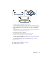
▼ Access the SP (Oracle ILOM)
You can access the server module’s SP either directly or through the CMM of the
modular system. You can manage the server module through the Oracle ILOM CLI
or through the Oracle ILOM web interface.
Use this procedure to log into the CMM to access the SP and to use the Oracle ILOM
CLI.
For alternative methods to access the server module SP, refer to the Server Module
Installation Guide.
1. Establish connectivity to the CMM using one of the following methods:
■
SER MGT port – Connect a terminal device (such as an ASCII terminal or
laptop with terminal emulation) to the CMM SER MGT port.
Set up your terminal device for 9600 baud, 8 bit, no parity, 1 stop bit, and no
handshaking, and use a null-modem configuration (transmit and receive signals
crossed over to enable DTE-to-DTE communication).
■
NET MGT port – Connect this CMM port to your Ethernet network. On the
CMM, this connector is labeled NET MGT. This port requires an IP address. By
default, this port uses DHCP to obtain and IP address, or you can assign a static
IP address.
Note – Alternatively, you can connect directly to the server module SP by using a
dongle cable to connect to the server module SER MGT or NET MGT ports. For more
information, refer to the Server Module Installation Guide.
2. Decide which interface to use.
■
Oracle ILOM CLI (default) – Most of the commands and examples in this
document use this interface. The default login account is root with a password
of changeme.
■
Oracle ILOM web interface – Can be used when you access the SP through the
NET MGT port and have a browser. Refer to the Oracle ILOM 3.0
documentation for details. This interface is not referenced in this document.
Detecting and Managing Faults
15
3. Open an SSH session to log into Oracle ILOM on the CMM.
The default Oracle ILOM login account is root with a default password of
changeme. The password might be different in your environment.
ssh root@CMM_IP_Address
Password:
Waiting for daemons to initialize...
Daemons ready
Oracle (R) Integrated Lights Out Manager
Version 3.0
Copyright (c) 2011, Oracle and/or its affiliates, Inc. All rights reserved.
Warning: password is set to factory default.
->
The Oracle ILOM prompt (->) indicates that you are accessing the Oracle ILOM
CLI.
4. Navigate to the server module.
-> cd /CH/BLn/SP/cli
Replace n with an integer that identifies the target server module (the slot in
which the server module is installed).
5. Start the server module SP Oracle ILOM CLI.
-> start
Are you sure you want to start /CH/BL0/SP/cli? y
start: Connecting to /CH/BL0/SP/cli using Single Sign On
6. Perform Oracle ILOM commands that provide the diagnostic information you
need.
These commands are commonly used for fault management:
■
show command – Displays information about individual FRUs.
See “Display FRU Information (show Command)” on page 17.
■
show faulty command – Displays environmental, POST-detected, and
PSH-detected faults.
See “Check for Faults (show faulty Command)” on page 18.
Note – You can use fmadm faulty in the Oracle ILOM faultmgmt shell as an
alternative to show faulty.
16
SPARC T4-1B Server Module Service Manual • November 2012
■
clear_fault_action property of the set command – Manually clears
PSH-detected faults.
See “Clear Faults (clear_fault_action Property)” on page 21.
Related Information
■
Oracle ILOM 3.0 documentation
■
“Display FRU Information (show Command)” on page 17
■
“Check for Faults (show faulty Command)” on page 18
■
“Check for Faults (fmadm faulty Command)” on page 20
■
“Clear Faults (clear_fault_action Property)” on page 21
■
“Service-Related Oracle ILOM Commands” on page 22
■
“Oracle ILOM Properties That Affect POST Behavior” on page 30
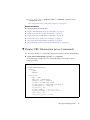
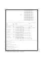
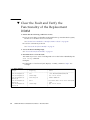
▼ Display FRU Information (show Command)
Use the Oracle ILOM show command to display information about individual FRUs.
●
At the Oracle ILOM prompt, type the show command.
In the following example, the show command displays information about a
memory module.
-> show /SYS/MB/CMP0/BOB0/CH0/D0
/SYS/MB/CMP0/BOB0/CH0/D0
Targets:
T_AMB
SERVICE
Properties:
Type = DIMM
ipmi_name = P0/B0/C0/D0
component_state = Enabled
fru_name = 8192MB DDR3 SDRAM
fru_description = DDR3 DIMM 8192 Mbytes
fru_manufacturer = Samsung
fru_version = 00
fru_part_number = ****************
fru_serial_number = ******************
fault_state = OK
clear_fault_action = (none)
Detecting and Managing Faults
17
Related Information
■
“Diagnostics Process” on page 7
■
“Access the SP (Oracle ILOM)” on page 15
■
“Check for Faults (show faulty Command)” on page 18
■
“Check for Faults (fmadm faulty Command)” on page 20
■
“Clear Faults (clear_fault_action Property)” on page 21
■
“Service-Related Oracle ILOM Commands” on page 22
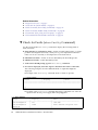
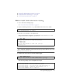
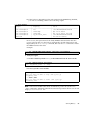
▼ Check for Faults (show faulty Command)
Use the Oracle ILOM show faulty command to display the following kinds of
faults and alerts:
■
Environmental or configuration faults – Faults caused by temperature or voltage
problems that might be caused by a faulty fan or power input. Environmental
faults can also be caused by room temperature or blocked air flow.
■
POST-detected faults – Faults on devices detected by the POST diagnostics.
■
PSH-detected faults – Faults detected by PSH.
1. At the Oracle ILOM prompt, type the show faulty command.
2. If a fault is displayed, check the output to determine the nature of the fault.
The following examples show the different kinds of output that might be
displayed:
■
Example of the show faulty command when no faults are present:
-> show faulty
Target
| Property
| Value
--------------------+------------------------+----------------------------------------------------------------------------------->
■
Example of the show faulty command displaying a fault when one of the AC
inputs for the chassis power supply PS0 is not plugged in:
-> show faulty
Target
| Property
| Value
--------------------+------------------------+------------------------------/SP/faultmgmt/0
| fru
| /SYS/PS0
/SP/faultmgmt/0
| class
| fault.chassis.env.power.loss
faults/0
|
|
18
SPARC T4-1B Server Module Service Manual • November 2012
/SP/faultmgmt/0
faults/0
/SP/faultmgmt/0
faults/0
/SP/faultmgmt/0
faults/0
/SP/faultmgmt/0
faults/0
/SP/faultmgmt/0
faults/0
/SP/faultmgmt/0
faults/0
->
■
|
|
|
|
|
|
|
|
|
|
|
|
sunw-msg-id
uuid
timestamp
detector
product_serial_number
chassis_serial_number
|
|
|
|
|
|
|
|
|
|
|
|
SPT-8000-5X
64d52ce4-614e-693f-bb71-ea3f829d
ad73
2011-10-14/20:14:13
/SYS/PS0/S1/V_IN_ERR
1030NND0D2
0000000-0000000000
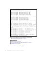
Example of the show faulty command displaying a fault that was detected by
POST. These kinds of faults are identified by the message Forced fail reason,
where reason is the name of the power-on routine that detected the fault. For
more information, see “Managing Faults (POST)” on page 29.
-> show faulty
Target
| Property
| Value
--------------------+------------------------+-------------------------------/SP/faultmgmt/0
| fru
| /SYS/MB/CMP0/BOB1/CH0/D0
/SP/faultmgmt/0/
| timestamp
| Oct 12 16:40:56
faults/0
|
|
/SP/faultmgmt/0/
| sp_detected_fault
| /SYS/MB/CMP0/BOB1/CH0/D0
faults/0
| Forced fail(POST)
■
Example of the show faulty command displaying a fault that was detected by
PSH. These kinds of faults are identified by the presence of a UUID value.
-> show faulty
Target
| Property
| Value
--------------------+------------------------+-------------------------------/SP/faultmgmt/0
| fru
| /SYS/MB
/SP/faultmgmt/0/
| class
| fault.fruid.replay
faults/0
|
|
/SP/faultmgmt/0/
| sunw-msg-id
| PCIEX-8000-8R
faults/0
|
|
/SP/faultmgmt/0/
| uuid
| c448cc2b-9f9e-4ae7-c494-c8fe99ed
faults/0
|
| dd58
/SP/faultmgmt/0/
| timestamp
| 2011-08-29/16:31:51
faults/0
|
|
/SP/faultmgmt/0/
| chassis_serial_number | *******-**********
faults/0
|
|
/SP/faultmgmt/0/
| product_serial_number | **********
faults/0
|
|
Detecting and Managing Faults
19
/SP/faultmgmt/0/
faults/0
/SP/faultmgmt/0/
faults/0
->
| fru_serial_number
|
| fru_part_number
|
| 465769T+**********
|
| 7015272
|
Related Information
■
“Diagnostics Process” on page 7
■
“Access the SP (Oracle ILOM)” on page 15
■
“Display FRU Information (show Command)” on page 17
■
“Check for Faults (fmadm faulty Command)” on page 20
■
“Clear Faults (clear_fault_action Property)” on page 21
■
“Service-Related Oracle ILOM Commands” on page 22
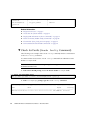
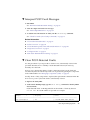
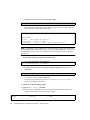
▼ Check for Faults (fmadm faulty Command)
The following is an example of the fmadm faulty command, which is an alternative
to the show faulty command.
You must run the Oracle Solaris fmadm faulty command from within the Oracle
ILOM faultmgmt shell.
Note – The characters SPT at the beginning of a message ID indicate that Oracle
ILOM detected the fault.
1. At the Oracle ILOM prompt, access the Oracle ILOM faultmgmt shell.
-> start /SP/faultmgmt/shell
Are you sure you want to start /SP/faultmgmt/shell (y/n)? y
2. At the faultmgmtsp> prompt, type the fmadm faulty command.
faultmgmtsp> fmadm faulty
------------------- ------------------------------------ ------------ ------Time
UUID
msgid
Severity
------------------- ------------------------------------ ------------ ------2011-08-11/14:54:23 ********-****-****-****-******* SPT-8000-LC Critical
...
20
SPARC T4-1B Server Module Service Manual • November 2012
3. Type the exit command when you are finished using the Oracle ILOM
faultmgt shell.
faultmgmtsp> exit
Related Information
■
“Diagnostics Process” on page 7
■
“Access the SP (Oracle ILOM)” on page 15
■
“Display FRU Information (show Command)” on page 17
■
“Check for Faults (show faulty Command)” on page 18
■
“Clear Faults (clear_fault_action Property)” on page 21
■
“Service-Related Oracle ILOM Commands” on page 22
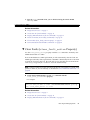
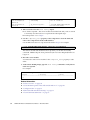
▼ Clear Faults (clear_fault_action Property)
Use the clear_fault_action property with the set command to manually clear
PSH-detected faults for a FRU.
If Oracle ILOM detects a FRU replacement, it will automatically clear the fault. For
PSH-diagnosed faults, if the replacement of the FRU is detected by the SP or the fault
is manually cleared on the host, the fault will also be cleared from Oracle ILOM. In
such cases, you typically do not have to clear the fault manually.
Note – This procedure clears the fault from the SP but not from the host. If the fault
persists in the host, clear it manually as described in “Clear PSH-Detected Faults” on
page 44.
●
At the Oracle ILOM prompt, use the set command with the
clear_fault_action=True property.
For example:
-> set /SYS/MB/CMP0/BOB0/CH0/D0 clear_fault_action=True
Are you sure you want to clear /SYS/MB/CMP0/BOB0/CH0/D0 (y/n)? y
Set ’clear_fault_action’ to ’true’
Related Information
■
“Diagnostics Process” on page 7
■
“Access the SP (Oracle ILOM)” on page 15
■
“Display FRU Information (show Command)” on page 17
Detecting and Managing Faults
21
■
“Check for Faults (show faulty Command)” on page 18
■
“Check for Faults (fmadm faulty Command)” on page 20
■
“Service-Related Oracle ILOM Commands” on page 22
Service-Related Oracle ILOM Commands
These are the Oracle ILOM shell commands most frequently used when performing
service-related tasks.
Oracle ILOM Command
Description
help [command]
Displays a list of all available commands with syntax
and descriptions. Specifying a command name as an
option displays help for that command.
set /HOST send_break_action=break
Takes the host server module from the OS to either
kmdb or OBP (equivalent to a Stop-A), depending on
the mode Oracle Solaris software was booted.
set /SYS/component clear_fault_action=true
Manually clears host-detected faults. The component is
the unique ID of the device with a fault to be cleared.
start /HOST/console
Connects to the host.
show /HOST/console/history
Displays the contents of the host’s console buffer.
set /HOST/bootmode property=value
Controls the host server module OBP firmware
method of booting. property is state, config, or
script
stop /SYS
start /SYS
Powers off the host server module and then powers on
the host server module.
stop /SYS
Powers off the host server module.
start /SYS
Powers on the host server module.
reset /SYS
Generates a hardware reset on the host server module.
reset /SP
Reboots the SP.
set /SYS keyswitch_state=value
Sets the virtual keyswitch. value is normal, standby,
diag, or locked.
set /SYS/LOCATE value=value
Turns the Locator LED on the server module on or off.
value is Fast_blink or Off.
show faulty
Displays current server module faults. See “Check for
Faults (show faulty Command)” on page 18.
show /SYS keyswitch_state
Displays the status of the virtual keyswitch.
22
SPARC T4-1B Server Module Service Manual • November 2012
Oracle ILOM Command
Description
show /SYS/LOCATE
Displays the current state of the Locator LED as either
on or off.
show /SP/logs/event/list
Displays the history of all events logged in the SP
event buffers (in RAM or the persistent buffers).
show /HOST
Displays information about the operating state of the
host, whether the hardware is providing service, and
firmware version information.
show /SYS
Displays information about the server module,
including the serial number.
Related Information
■
“Oracle ILOM Troubleshooting Overview” on page 12
■
“Access the SP (Oracle ILOM)” on page 15
■
“Display FRU Information (show Command)” on page 17
■
“Check for Faults (show faulty Command)” on page 18
■
“Check for Faults (fmadm faulty Command)” on page 20
■
“Clear Faults (clear_fault_action Property)” on page 21
■
“Oracle ILOM Properties That Affect POST Behavior” on page 30
Interpreting Log Files and System
Messages
With the Oracle Solaris OS running on the server module, you have the full
complement of Oracle Solaris OS files and commands available for collecting
information and for troubleshooting.
If POST or the PSH features do not indicate the source of a fault, check the message
buffer and log files for notifications for faults. Drive faults are usually captured by
the Oracle Solaris message files.
■
“Check the Message Buffer (dmesg Command)” on page 24
■
“View System Message Log Files” on page 24
■
“List FRU Status (prtdiag Command)” on page 25
Detecting and Managing Faults
23
Related Information
■
“Diagnostics Overview” on page 5
■
“Diagnostics Process” on page 7
■
“Managing Faults (Oracle ILOM)” on page 11
■
“Managing Faults (PSH)” on page 41
■
“Managing Faults (POST)” on page 29
■
“Managing Components (ASR)” on page 45
■
“Checking if Oracle VTS Software Is Installed” on page 27
▼ Check the Message Buffer (dmesg Command)
The dmesg command checks the system buffer for recent diagnostic messages and
displays them.
1. Log in as superuser.
2. Type.
# dmesg
Related Information
■
“View System Message Log Files” on page 24
■
“List FRU Status (prtdiag Command)” on page 25
▼ View System Message Log Files
The error logging daemon, syslogd, automatically records various system
warnings, errors, and faults in message files. These messages can alert you to system
problems such as a device that is about to fail.
The /var/adm directory contains several message files. The most recent messages
are in the /var/adm/messages file. After a period of time (usually every week), a
new message file is automatically created. The original contents of the messages
file are rotated to a file named messages.0. Over a period of time, the messages are
further rotated to messages.1 and messages.2, and then deleted.
1. Log in as superuser.
24
SPARC T4-1B Server Module Service Manual • November 2012
2. Type.
# more /var/adm/messages
Or, if you want to view all logged messages, type:
# more /var/adm/messages*
Related Information
■
“Check the Message Buffer (dmesg Command)” on page 24
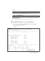
▼ List FRU Status (prtdiag Command)
●
At an Oracle Solaris OS command line, type the prtdiag command.
FRU status information is displayed.
Example:
# prtdiag
System Configuration: Oracle Corporation
Memory size: 130560 Megabytes
sun4v SPARC T4-1B
================================ Virtual CPUs ================================
CPU ID
-----0
1
2
<...>
<...>
61
62
63
Frequency
--------2848 MHz
2848 MHz
2848 MHz
Implementation
---------------------SPARC-T4
SPARC-T4
SPARC-T4
Status
------on-line
on-line
on-line
2848 MHz
2848 MHz
2848 MHz
SPARC-T4
SPARC-T4
SPARC-T4
on-line
on-line
on-line
======================= Physical Memory Configuration ========================
Segment Table:
-------------------------------------------------------------Base
Segment Interleave Bank
Contains
Address
Size
Factor
Size
Modules
-------------------------------------------------------------0x0
128 GB
2
64 GB
/SYS/MB/CMP0/BOB0/CH0/D0
/SYS/MB/CMP0/BOB0/CH0/D1
Detecting and Managing Faults
25
64 GB
/SYS/MB/CMP0/BOB0/CH1/D0
/SYS/MB/CMP0/BOB0/CH1/D1
/SYS/MB/CMP0/BOB1/CH0/D0
/SYS/MB/CMP0/BOB1/CH0/D1
/SYS/MB/CMP0/BOB1/CH1/D0
/SYS/MB/CMP0/BOB1/CH1/D1
/SYS/MB/CMP0/BOB2/CH0/D0
/SYS/MB/CMP0/BOB2/CH0/D1
/SYS/MB/CMP0/BOB2/CH1/D0
/SYS/MB/CMP0/BOB2/CH1/D1
/SYS/MB/CMP0/BOB3/CH0/D0
/SYS/MB/CMP0/BOB3/CH0/D1
/SYS/MB/CMP0/BOB3/CH1/D0
/SYS/MB/CMP0/BOB3/CH1/D1
================================ IO Devices ================================
Slot +
Bus
Name +
Model
Status
Type Path
---------------------------------------------------------------------------/SYS/MB/REM
PCIE LSI,sas-pciex1000,72
LSI,2008
/pci@400/pci@1/pci@0/pci@c/LSI,sas@0
/SYS/MB/FEM0
PCIE network-pciex108e,aaaa
SUNW,pcie-hydra
/pci@400/pci@2/pci@0/pci@6/network@0
/SYS/MB/NET0
PCIE network-pciex8086,10c9
/pci@400/pci@2/pci@0/pci@c/network@0
/SYS/MB/NET1
PCIE network-pciex8086,10c9
/pci@400/pci@2/pci@0/pci@c/network@0,1
/SYS/MB/USB
PCIE usb-pciclass,0c0310
/pci@400/pci@1/pci@0/pci@0/pci@0/usb@0
/SYS/MB/USB
PCIE usb-pciclass,0c0310
/pci@400/pci@1/pci@0/pci@0/pci@0/usb@0,1
/SYS/MB/USB
PCIE usb-pciclass,0c0320
/pci@400/pci@1/pci@0/pci@0/pci@0/usb@0,2
/SYS/MB/VIDEO
PCIX display-pci1a03,2000
/pci@400/pci@2/pci@0/pci@d/pci@0/display@0
============================ Environmental Status ============================
Fan sensors:
All fan sensors are OK.
Fan indicators:
All fan indicators are OK.
Temperature sensors:
All temperature sensors are OK.
Temperature indicators:
All temperature indicators are OK.
26
SPARC T4-1B Server Module Service Manual • November 2012
Current sensors:
All current sensors are OK.
Current indicators:
All current indicators are OK.
Voltage sensors:
All voltage sensors are OK.
Voltage indicators:
All voltage indicators are OK.
============================ FRU Status ============================
All FRUs are enabled.
Related Information
■
“Check the Message Buffer (dmesg Command)” on page 24
■
“View System Message Log Files” on page 24
■
“Display FRU Information (show Command)” on page 17
Checking if Oracle VTS Software Is
Installed
Oracle VTS (previously named SunVTS) is a validation test suite that you can use to
test this server module. These topics provide an overview and a way to check if
Oracle VTS is installed. For comprehensive Oracle VTS information, refer to the
Oracle VTS documentation.
■
“Oracle VTS Overview” on page 28
■
“Check if Oracle VTS Software Is Installed” on page 28
Related Information
■
“Diagnostics Overview” on page 5
■
“Diagnostics Process” on page 7
■
“Managing Faults (Oracle ILOM)” on page 11
■
“Interpreting Log Files and System Messages” on page 23
■
“Managing Faults (PSH)” on page 41
Detecting and Managing Faults
27
■
“Managing Faults (POST)” on page 29
■
“Managing Components (ASR)” on page 45
Oracle VTS Overview
Oracle VTS is a validation test suite that you can use to test this server module.
Oracle VTS provides multiple diagnostic hardware tests that verify the connectivity
and functionality of most hardware controllers and devices for this server module.
The software provides these kinds of test categories:
■
Audio
■
Communication (serial and parallel)
■
Graphic and video
■
Memory
■
Network
■
Peripherals (hard drives, CD-DVD devices, and printers)
■
Processor
■
Storage
Use Oracle VTS to validate a server module during development, production,
receiving inspection, troubleshooting, periodic maintenance, and system or
subsystem stressing.
You can run Oracle VTS through a web browser, a terminal, or CLI.
You can run tests in a variety of modes for online and offline testing.
Oracle VTS also provides a choice of security mechanisms.
Oracle VTS software is provided in the preinstalled Oracle Solaris OS that shipped
with the server module.
Related Information
■
Oracle VTS documentation
■
“Check if Oracle VTS Software Is Installed” on page 28
▼ Check if Oracle VTS Software Is Installed
1. Log in as superuser.
28
SPARC T4-1B Server Module Service Manual • November 2012
2. Check for the presence of Oracle VTS packages.
# pkginfo -l SUNWvts SUNWvtsr SUNWvtsts SUNWvtsmn
■
If information about the packages is displayed, then Oracle VTS software is
installed.
■
If you receive messages reporting ERROR: information for package was
not found, then Oracle VTS is not installed. You must install the software
before you can use it. You can obtain the Oracle VTS software from the
following places:
■
Oracle Solaris OS media kit (DVDs)
■
As a download from the web
Related Information
■
Oracle VTS documentation
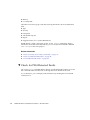
Managing Faults (POST)
These topics explain how to use POST as a diagnostic tool.
■
“POST Overview” on page 30
■
“Oracle ILOM Properties That Affect POST Behavior” on page 30
■
“Configure POST” on page 33
■
“Run POST With Maximum Testing” on page 35
■
“Interpret POST Fault Messages” on page 37
■
“Clear POST-Detected Faults” on page 37
■
“POST Output Reference” on page 39
Related Information
■
“Diagnostics Overview” on page 5
■
“Diagnostics Process” on page 7
■
“Managing Faults (Oracle ILOM)” on page 11
■
“Interpreting Log Files and System Messages” on page 23
■
“Managing Faults (PSH)” on page 41
■
“Managing Components (ASR)” on page 45
■
“Checking if Oracle VTS Software Is Installed” on page 27
Detecting and Managing Faults
29
POST Overview
POST is a group of PROM-based tests that run when the server module is powered
on or when it is reset. POST checks the basic integrity of the critical hardware
components in the server module (CPU, memory, and I/O subsystem).
You can also run POST as a system-level hardware diagnostic tool. To do this, use the
Oracle ILOM set command to set the parameter keyswitch_state to diag.
You can also set other Oracle ILOM properties to control various other aspects of
POST operations. For example, you can specify the events that cause POST to run,
the level of testing POST performs, and the amount of diagnostic information POST
displays. These properties are listed and described in “Oracle ILOM Properties That
Affect POST Behavior” on page 30.
If POST detects a faulty component, the component is disabled automatically. If the
server module is able to run without the disabled component, it will boot when
POST completes its tests. For example, if POST detects a faulty processor core, the
core will be disabled. After POST completes its test sequence, the server module
boots and uses the remaining cores.
Related Information
■
“Diagnostics Overview” on page 5
■
“Oracle ILOM Properties That Affect POST Behavior” on page 30
■
“Configure POST” on page 33
■
“Run POST With Maximum Testing” on page 35
■
“Interpret POST Fault Messages” on page 37
■
“Clear POST-Detected Faults” on page 37
■
“POST Output Reference” on page 39
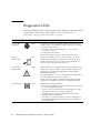
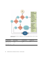
Oracle ILOM Properties That Affect POST
Behavior
These Oracle ILOM properties determine how POST performs its operations. See also
the flowchart that follows the table.
Note – The value of keyswitch_state must be normal when individual POST
parameters are changed.
30
SPARC T4-1B Server Module Service Manual • November 2012
Parameter
Values
Description
/SYS keyswitch_state
normal
The host can power on and run POST (based on the
other parameter settings). This parameter overrides
all other commands.
diag
The host runs POST based on predetermined settings
that perform maximum verbose testing.
standby
The host cannot power on.
locked
The host can power on and run POST, but no flash
updates can be made.
off
POST does not run.
normal
Runs POST according to diag level value.
service
Runs POST with preset values for diag level and
diag verbosity.
max
If diag mode = normal, runs all the minimum tests
plus extensive processor and memory tests.
min
If diag mode = normal, runs the minimum set of
tests.
none
Does not run POST on reset.
hw-change
(Default) Runs POST following an AC power cycle
and when the top cover is removed.
power-on-reset
Runs POST only for the first power on.
error-reset
(Default) Runs POST if fatal errors are detected.
all-resets
Runs POST after any reset.
normal
POST output displays all test and informational
messages.
min
POST output displays functional tests with a banner
and pinwheel.
max
POST displays all test and informational messages,
and some debugging messages.
debug
POST displays extensive debugging output on the
system console, including the devices being tested
and the debug output of each test.
none
No POST output is displayed.
/HOST/diag mode
/HOST/diag level
/HOST/diag trigger
/HOST/diag verbosity
Detecting and Managing Faults
31
The following table shows combinations of Oracle ILOM parameters and associated
POST modes.
Oracle ILOM Parameter
Normal Diagnostic Mode
(Default Settings)
No POST Execution
Service Mode Using the
Keyswitch_state
keyswitch_state*
normal
normal
diag
/HOST/diag mode
normal
Off
/HOST/diag level
max
32
SPARC T4-1B Server Module Service Manual • November 2012
Oracle ILOM Parameter
Normal Diagnostic Mode
(Default Settings)
No POST Execution
/HOST/diag trigger
hw-change error-reset
none
Service Mode Using the
Keyswitch_state
/HOST/diag verbosity normal
Description of POST
execution
This is the default POST
configuration. This
configuration tests the server
module thoroughly and
suppresses some of the
detailed POST output.
POST does not run,
resulting in quick
initialization. This
configuration is not
suggested.
POST runs the full
spectrum of tests with
the maximum output
displayed.
* The keyswitch_state parameter, when set to diag, overrides all the other POST variables.
Related Information
■
“POST Overview” on page 30
■
“Configure POST” on page 33
■
“Run POST With Maximum Testing” on page 35
■
“Interpret POST Fault Messages” on page 37
■
“Clear POST-Detected Faults” on page 37
■
“POST Output Reference” on page 39
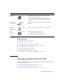
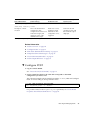
▼ Configure POST
1. Log in to Oracle ILOM.
See “Access the SP (Oracle ILOM)” on page 15.
2. Set the virtual keyswitch to the value that corresponds to the POST
configuration you want to run.
The following example sets the virtual keyswitch to normal, which will configure
POST to run according to other parameter values.
-> set /SYS keyswitch_state=normal
Set ‘keyswitch_state' to ‘Normal'
For possible values for the keyswitch_state parameter, see “Oracle ILOM
Properties That Affect POST Behavior” on page 30.
Detecting and Managing Faults
33
3. If the virtual keyswitch is set to normal, and you want to define the mode,
level, verbosity, or trigger, set the respective parameters.
Syntax:
set /HOST/diag property=value
See “Oracle ILOM Properties That Affect POST Behavior” on page 30 for a list of
parameters and values.
For examples:
-> set /HOST/diag mode=normal
or
-> set /HOST/diag verbosity=max
4. To see the current values for settings, use the show command.
For example, showing default values:
-> show /HOST/diag
/HOST/diag
Targets:
Properties:
error_reset_level = max
error_reset_verbosity = normal
hw_change_level = max
hw_change_verbosity = normal
level = max
mode = normal
power_on_level = max
power_on_verbosity = normal
trigger = hw-change error-reset
verbosity = normal
Commands:
cd
set
show
->
Related Information
34
■
“POST Overview” on page 30
■
“Oracle ILOM Properties That Affect POST Behavior” on page 30
SPARC T4-1B Server Module Service Manual • November 2012
■
“Run POST With Maximum Testing” on page 35
■
“Interpret POST Fault Messages” on page 37
■
“Clear POST-Detected Faults” on page 37
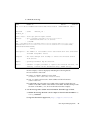
▼ Run POST With Maximum Testing
1. Access the Oracle ILOM prompt.
See “Access the SP (Oracle ILOM)” on page 15.
2. Set the virtual keyswitch to diag so that POST will run in service mode.
-> set /SYS/keyswitch_state=diag
Set ‘keyswitch_state' to ‘Diag'
3. Reset the server module so that POST runs.
There are several ways to initiate a reset. The following example shows a reset
using commands that will power cycle the host.
-> stop /SYS
Are you sure you want to stop /SYS (y/n)? y
Stopping /SYS
-> start /SYS
Are you sure you want to start /SYS (y/n)? y
Starting /SYS
Note – The server module takes about one minute to power off. Type the show
/HOST command to determine when the host has been powered off. The console will
display status=Powered Off.
4. Switch to the host console to view the POST output.
-> start /HOST/console
Are you sure you want to start /HOST/console (y/n)? y
The following example shows abridged POST output.
Serial console started. To stop, type #.
[CPU 0:0:0] NOTICE: Checking Flash File System
[CPU 0:0:0] NOTICE: Initializing TOD: 2011/08/30 00:38:11
[CPU 0:0:0] NOTICE: Loaded ASR status DB data. Ver. 2.
[CPU 0:0:0] WARNING: TPM not supported
Detecting and Managing Faults
35
[CPU 0:0:0] NOTICE: Serial#:
0000000000000000.000900802c1cf133
[CPU 0:0:0] NOTICE: Version:
003e003012030607
[CPU 0:0:0] NOTICE: T4 Revision: 1.2
[CPU 0:0:0] NOTICE: MCU0: Memory Capacity is 64GB
[CPU 0:0:0] NOTICE: MCU1: Memory Capacity is 64GB
[CPU 0:0:0] NOTICE: Usable strands: ffffffffffffffff
[CPU 0:0:0] NOTICE: System memory capacity is 128GB
[CPU 0:0:0] NOTICE: Clocks: CMP: 2848 MHz DRAM: 533 MHz (6.4 Gbps)
CL: 1466 MHz (8.8 Gbps)
[CPU 0:0:0] NOTICE: Initializing TSR Hoovers
[CPU 0:0:0] NOTICE: Initializing FSR Hoovers
[CPU 0:0:0] NOTICE: Initializing MCU 0 serdes
[CPU 0:0:0] NOTICE: Initializing MCU 1 serdes
[CPU 0:0:0] NOTICE: Updating Config Information for Guest Manager
<...>
<...>
2011-08-30 00:47:29.301 0:0:0>| NODE:PORT 0:1 | AST2200
|
Addr: f850.01000000 | BDF 16: 0:0 | VID-1a03 | DID-1150 | Width=01
G1 |
2011-08-30 00:47:29.351 0:0:0>| NODE:PORT 0:1 | AST2100 Display
| Addr: f850.01100000 | BDF 17: 0:0 | VID-1a03 | DID-2000 | Width=
00 G0 |
2011-08-30 00:47:31.388 0:0:0>
PCIE PROBE Node 0 port 1,
devices found = 12
2011-08-30 00:47:31.404 0:0:0>
PCIE PROBE devices found = 23
2011-08-30 00:47:31.439 0:0:0>End : Probe PCI Devices
2011-08-30 00:47:31.452 0:0:0>Begin: Network Tests
2011-08-30 00:47:31.496 0:0:0>End : Network Tests
2011-08-30 00:47:31.555 0:0:0>INFO:
2011-08-30 00:47:31.563 0:0:0>
POST Passed all devices.
2011-08-30 00:47:31.576 0:0:0>POST:
Return to Host Config.
[CPU 0:0:0] NOTICE: Reconfiguring System
5. If you receive POST error messages, learn how to interpret them.
See “Interpret POST Fault Messages” on page 37.
Related Information
36
■
“POST Overview” on page 30
■
“Oracle ILOM Properties That Affect POST Behavior” on page 30
■
“Configure POST” on page 33
■
“Interpret POST Fault Messages” on page 37
■
“Clear POST-Detected Faults” on page 37
SPARC T4-1B Server Module Service Manual • November 2012
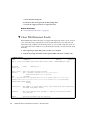
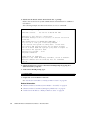
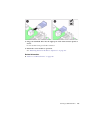
▼ Interpret POST Fault Messages
1. Run POST.
See “Run POST With Maximum Testing” on page 35.
2. View the output and watch for messages.
See “POST Output Reference” on page 39.
3. To obtain more information on faults, run the show faulty command.
See “Check for Faults (show faulty Command)” on page 18.
Related Information
■
“Clear POST-Detected Faults” on page 37
■
“POST Overview” on page 30
■
“Oracle ILOM Properties That Affect POST Behavior” on page 30
■
“Diagnostics Overview” on page 5
■
“Configure POST” on page 33
■
“Run POST With Maximum Testing” on page 35
▼ Clear POST-Detected Faults
Use this procedure if you suspect that a fault was not automatically cleared. This
procedure describes how to identify a POST-detected fault and, if necessary,
manually clear the fault.
In most cases, when POST detects a faulty component, POST logs the fault and
automatically takes the failed component out of operation by placing the component
in the ASR blacklist. See “Managing Components (ASR)” on page 45.
Usually, when a faulty component is replaced, the replacement is detected when the
SP is reset or power cycled. The fault is automatically cleared.
1. Replace the faulty FRU.
2. At the Oracle ILOM prompt, type the show faulty command to identify POST
detected faults.
POST-detected faults are distinguished from other kinds of faults by the text:
Forced fail. No UUID number is reported. For example:
-> show faulty
Target
| Property
| Value
----------------------+------------------------+----------------------------/SP/faultmgmt/0
| fru
| /SYS/MB/CMP0/BOB1/CH0/D0
Detecting and Managing Faults
37
/SP/faultmgmt/0
/SP/faultmgmt/0/
faults/0
/SP/faultmgmt/0/
faults/0
| timestamp
| timestamp
|
| sp_detected_fault
|
|
|
|
|
|
Dec 21 16:40:56
Dec 21 16:40:56
/SYS/MB/CMP0/BOB1/CH0/D0
Forced fail(POST)
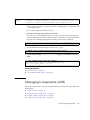
3. Take action based on the show faulty output.
■
No fault is reported – The server module cleared the fault and you do not need
to manually clear the fault. Do not perform the subsequent steps.
■
Fault reported – Go to Step 4.
4. Use the component_state property of the component to clear the fault and
remove the component from the ASR blacklist.
Use the FRU name that was reported in the fault in Step 2. For example:
-> set /SYS/MB/CMP0/BOB1/CH0/D0 component_state=Enabled
The fault is cleared and should not show up when you run the show faulty
command. Additionally, the front panel Fault (Service Action Required) LED is no
longer on.
5. Reset the server module.
You must reboot the server module for the component_state property to take
effect.
6. At the Oracle ILOM prompt, type the show faulty command to verify that no
faults are reported.
For example:
-> show faulty
Target
| Property
| Value
--------------------+------------------------+------------------>
Related Information
38
■
“POST Overview” on page 30
■
“Oracle ILOM Properties That Affect POST Behavior” on page 30
■
“Configure POST” on page 33
■
“Run POST With Maximum Testing” on page 35
■
“Clear POST-Detected Faults” on page 37
SPARC T4-1B Server Module Service Manual • November 2012
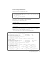
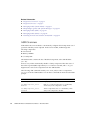
POST Output Reference
POST error messages use the following syntax:
c:s >
c:s >
c:s >
under
c:s >
c:s >
ERROR: TEST = failing-test
H/W under test = FRU
Repair Instructions: Replace items in order listed by H/W
test above
MSG = test-error-message
END_ERROR
In this syntax, c = the core number, s = the strand number.
Warning messages use the following syntax:
WARNING: message
Informational messages use the following syntax:
INFO: message
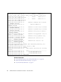
In the following example, POST reports an uncorrectable memory error affecting
DIMM locations /SYS/MB/CMP0/BOB0/CH0/D0 and
/SYS/MB/CMP0/BOB1/CH0/D0. The error was detected by POST.
2011-07-03 18:44:13.359 0:7:2>Decode of Disrupting Error Status Reg
(DESR HW Corrected) bits 00300000.00000000
2011-07-03 18:44:13.517 0:7:2>
1
DESR_SOCSRE:
SOC
(non-local) sw_recoverable_error.
2011-07-03 18:44:13.638 0:7:2>
1
DESR_SOCHCCE:
SOC
(non-local) hw_corrected_and_cleared_error.
2011-07-03 18:44:13.773 0:7:2>
2011-07-03 18:44:13.836 0:7:2>Decode of NCU Error Status Reg bits
00000000.22000000
2011-07-03 18:44:13.958 0:7:2>
1
NESR_MCU1SRE:
MCU1 issued
a Software Recoverable Error Request
2011-07-03 18:44:14.095 0:7:2>
1
NESR_MCU1HCCE:
MCU1
issued a Hardware Corrected-and-Cleared Error Request
2011-07-03 18:44:14.248 0:7:2>
2011-07-03 18:44:14.296 0:7:2>Decode of Mem Error Status Reg Branch 1
bits 33044000.00000000
2011-07-03 18:44:14.427 0:7:2>
1
MEU 61
R/W1C Set to 1
on an UE if VEU = 1, or VEF = 1, or higher priority error in same cycle.
2011-07-03 18:44:14.614 0:7:2>
1
MEC 60
R/W1C Set to 1
on a CE if VEC = 1, or VEU = 1, or VEF = 1, or another error in same cycle.
2011-07-03 18:44:14.804 0:7:2>
1
VEU 57
R/W1C Set to 1
Detecting and Managing Faults
39
on an UE, if VEF = 0 and no fatal error is detected in same cycle.
2011-07-03 18:44:14.983 0:7:2>
1
VEC 56
R/W1C Set to 1
on a CE, if VEF = VEU = 0 and no fatal or UE is detected in same cycle.
2011-07-03 18:44:15.169 0:7:2>
1
DAU 50
R/W1C Set to 1
if the error was a DRAM access UE.
2011-07-03 18:44:15.304 0:7:2>
1
DAC 46
R/W1C Set to 1
if the error was a DRAM access CE.
2011-07-03 18:44:15.440 0:7:2>
2011-07-03 18:44:15.486 0:7:2>
DRAM Error Address Reg for Branch
1 = 00000034.8647d2e0
2011-07-03 18:44:15.614 0:7:2>
Physical Address is
00000005.d21bc0c0
2011-07-03 18:44:15.715 0:7:2>
DRAM Error Location Reg for Branch
1 = 00000000.00000800
2011-07-03 18:44:15.842 0:7:2>
DRAM Error Syndrome Reg for Branch
1 = dd1676ac.8c18c045
2011-07-03 18:44:15.967 0:7:2>
DRAM Error Retry Reg for Branch 1
= 00000000.00000004
2011-07-03 18:44:16.086 0:7:2>
DRAM Error RetrySyndrome 1 Reg for
Branch 1 = a8a5f81e.f6411b5a
2011-07-03 18:44:16.218 0:7:2>
DRAM Error Retry Syndrome 2 Reg
for Branch 1 = a8a5f81e.f6411b5a
2011-07-03 18:44:16.351 0:7:2>
DRAM Failover Location 0 for
Branch 1 = 00000000.00000000
2011-07-03 18:44:16.475 0:7:2>
DRAM Failover Location 1 for
Branch 1 = 00000000.00000000
2011-07-03 18:44:16.604 0:7:2>
2011-07-03 18:44:16.648 0:7:2>ERROR: POST terminated prematurely. Not
all system components tested.
2011-07-03 18:44:16.786 0:7:2>POST: Return to VBSC
2011-07-03 18:44:16.795 0:7:2>ERROR:
2011-07-03 18:44:16.839 0:7:2>
POST toplevel status has the following
failures:
2011-07-03 18:44:16.952 0:7:2>
Node 0 ------------------------------2011-07-03 18:44:17.051 0:7:2>
/SYS/MB/CMP0/BOB0/CH1/D0
2011-07-03 18:44:17.145 0:7:2>
/SYS/MB/CMP0/BOB1/CH1/D0
2011-07-03 18:44:17.241 0:7:2>END_ERROR
Related Information
40
■
“Oracle ILOM Properties That Affect POST Behavior” on page 30
■
“Run POST With Maximum Testing” on page 35
■
“Clear POST-Detected Faults” on page 37
SPARC T4-1B Server Module Service Manual • November 2012
Managing Faults (PSH)
These topics describe the PSH feature:
■
“PSH Overview” on page 41
■
“Check for PSH-Detected Faults” on page 42
■
“Clear PSH-Detected Faults” on page 44
Related Information
■
“Diagnostics Overview” on page 5
■
“Diagnostics Process” on page 7
■
“Managing Faults (Oracle ILOM)” on page 11
■
“Interpreting Log Files and System Messages” on page 23
■
“Managing Faults (POST)” on page 29
■
“Managing Components (ASR)” on page 45
■
“Checking if Oracle VTS Software Is Installed” on page 27
■
“POST Overview” on page 30
PSH Overview
The Oracle Solaris PSH technology enables the server module to diagnose problems
while the Oracle Solaris OS is running and to mitigate many problems before they
negatively affect operations.
The Oracle Solaris OS uses the fault manager daemon, fmd(1M), which starts at boot
time and runs in the background to monitor the server module. If a component
generates an error, the daemon correlates the error with data from previous errors
and other relevant information to diagnose the problem. Once diagnosed, the fault
manager daemon assigns a UUID to the error. This value distinguishes this error
across any set of server modules.
When possible, the fault manager daemon initiates steps to self-heal the failed
component and take the component offline. The daemon also logs the fault to the
syslogd daemon and provides a fault notification with a message ID (sometimes
labeled MSG-ID). You can use the message ID to get additional information about the
problem from the knowledge article database.
The PSH technology covers the following server module components:
■
CPU
Detecting and Managing Faults
41
■
Memory
■
I/O subsystem
The PSH console message provides the following information about each detected
fault:
■
Type
■
Severity
■
Description
■
Automated response
■
Impact
■
Suggested action for a system administrator
If PSH detects a faulty component, use the fmadm faulty command to display
information about the fault. Alternatively, you can use the Oracle ILOM command
show faulty for the same purpose.
Related Information
■
“Check for Faults (show faulty Command)” on page 18
■
“Check for PSH-Detected Faults” on page 42
■
“Clear PSH-Detected Faults” on page 44
▼ Check for PSH-Detected Faults
The fmadm faulty command displays the list of faults detected by PSH. You can run
this command either from the host or through the Oracle ILOM fmadm shell.
As an alternative, you can display fault information by running the Oracle ILOM
command show.
42
SPARC T4-1B Server Module Service Manual • November 2012
1. Check the event log.
# fmadm faulty
TIME
EVENT-ID
Aug 13 11:48:33 21a8b59e-89ff-692a-c4bc-f4c5cccca8c8
Platform
Product_sn
: sun4v
:
Chassis_id
MSG-ID
SUN4V-8002-6E
SEVERITY
Major
:
Fault class : fault.cpu.generic-sparc.strand
Affects
: cpu:///cpuid=**/serial=*********************
faulted and taken out of service
FRU
: "/SYS/MB"
(hc://:product-id=*****:product-sn=**********:server-id=***-******-*****:
chassis-id=********:**************-**********:serial=******:revision=05/
chassis=0/motherboard=0)
faulty
Description : The number of correctable errors associated with this strand has
exceeded acceptable levels.
Response
: The fault manager will attempt to remove the affected strand
from service.
Impact
: System performance may be affected.
Action
: Schedule a repair procedure to replace the affected resource, the
identity of which can be determined using ’fmadm faulty’.
In this example, a fault is displayed, indicating the following details:
■
Date and time of the fault.
■
EVENT-ID, which is unique for every fault
(21a8b59e-89ff-692a-c4bc-f4c5cccca8c8).
■
MSG-ID, which can be used to obtain additional fault information
(SUN4V-8002-6E).
■
Faulted FRU. The information provided in the example includes the part
number of the FRU and the serial number of the FRU. The FRU field provides
the name of the FRU (/SYS/MB for motherboard in this example).
2. Use the message ID to obtain more information about this type of fault.
a. Obtain the message ID from console output or from the Oracle ILOM show
faulty command.
b. Sign into the Oracle support site, http://support.oracle.com.
Detecting and Managing Faults
43
c. Select the Knowledge tab.
d. Search for that message ID in the Knowledge Base.
e. Follow the suggested actions to repair the fault.
Related Information
■
“Clear PSH-Detected Faults” on page 44
▼ Clear PSH-Detected Faults
When PSH detects faults, the faults are logged and displayed on the console. In most
cases, after the fault is repaired, the server module detects the corrected state and
repairs the fault condition automatically. However, you should verify this repair. In
cases where the fault condition is not automatically cleared, you must clear the fault
manually.
1. After replacing a faulty FRU, power on the server module.
2. At the host prompt, determine if the replaced FRU still shows a faulty state.
# fmadm faulty
TIME
EVENT-ID
Aug 13 11:48:33 21a8b59e-89ff-692a-c4bc-f4c5cccca8c8
Platform
Product_sn
: sun4v
:
Chassis_id
MSG-ID
SUN4V-8002-6E
SEVERITY
Major
:
Fault class : fault.cpu.generic-sparc.strand
Affects
: cpu:///cpuid=**/serial=*********************
faulted and taken out of service
FRU
: "/SYS/MB"
(hc://:product-id=*****:product-sn=**********:server-id=***-******-*****:
chassis-id=********:**************-**********:serial=******:revision=05/
chassis=0/motherboard=0)
faulty
Description : The number of correctable errors associated with this strand has
exceeded acceptable levels.
Response
: The fault manager will attempt to remove the affected strand
from service.
Impact
: System performance may be affected.
44
SPARC T4-1B Server Module Service Manual • November 2012
Action
: Schedule a repair procedure to replace the affected resource, the
identity of which can be determined using ’fmadm faulty’.
■
If no fault is reported, you do not need to do anything else. Do not perform the
subsequent steps.
■
If a fault is reported, continue to Step 3.
3. Clear the fault from all persistent fault records.
In some cases, even though the fault is cleared, some persistent fault information
remains and results in erroneous fault messages at boot time. To ensure that these
messages are not displayed, type the following Oracle Solaris command:
# fmadm repair EVENT-ID
For the EVENT-ID in the example shown in Step 2, type:
# fmadm repair 21a8b59e-89ff-692a-c4bc-f4c5cccca8c8
4. Use the Oracle ILOM clear_fault_action property of the FRU to clear the
fault.
-> set /SYS/MB clear_fault_action=True
Are you sure you want to clear /SYS/MB (y/n)? y
set ’clear_fault_action’ to ’true
Related Information
■
“PSH Overview” on page 41
■
“Clear PSH-Detected Faults” on page 44
Managing Components (ASR)
These topics explain the role played by ASR and how to manage the components that
ASR controls.
■
“ASR Overview” on page 46
■
“Display System Components” on page 47
■
“Disable System Components” on page 48
■
“Enable System Components” on page 49
Detecting and Managing Faults
45
Related Information
■
“Diagnostics Overview” on page 5
■
“Diagnostics Process” on page 7
■
“Managing Faults (Oracle ILOM)” on page 11
■
“Interpreting Log Files and System Messages” on page 23
■
“Managing Faults (PSH)” on page 41
■
“Managing Faults (POST)” on page 29
■
“Checking if Oracle VTS Software Is Installed” on page 27
ASR Overview
ASR enables the server module to automatically configure failed components out of
operation until they can be replaced. In the server module, ASR manages the
following components:
■
CPU strands
■
Memory DIMMs
■
I/O subsystem
The database that contains the list of disabled components is the ASR blacklist
(asr-db).
In most cases, POST automatically disables a faulty component. After the cause of
the fault is repaired (FRU replacement, loose connector reseated, and so on), you
might need to remove the component from the ASR blacklist.
The following ASR commands enable you to view, add, or remove components
(asrkeys) from the ASR blacklist. You run these commands from the Oracle ILOM
prompt.
46
Command
Description
show components
Displays system components and their current state.
set asrkey component_state=
Enabled
Removes a component from the asr-db blacklist,
where asrkey is the component to enable.
set asrkey component_state=
Disabled
Adds a component to the asr-db blacklist, where
asrkey is the component to disable.
SPARC T4-1B Server Module Service Manual • November 2012
Note – The asrkey values vary from system to system, depending on how many
cores and memory are present. Use the show components command to see the
asrkey values on a given system.
After you enable or disable a component, you must reset (or power cycle) the server
module for the component’s change of state to take effect. See the Server Module
Administration Guide
Related Information
■
“Display System Components” on page 47
■
“Disable System Components” on page 48
■
“Enable System Components” on page 49
▼ Display System Components
The show components command displays the system components (asrkeys) and
reports their status.
●
At the Oracle ILOM prompt, type show components.
In the following example, one of the DIMMs (BOB1/CH0/D0) is shown as
disabled.
->show components
Target
| Property
| Value
--------------------+------------------------+------------------------------/SYS/MB/REM
| component_state
| Enabled
/SYS/MB/FEM0
| component_state
| Enabled
/SYS/MB/CMP0/L2T0
| component_state
| Enabled
/SYS/MB/CMP0/L2T1
| component_state
| Enabled
/SYS/MB/CMP0/L2T2
| component_state
| Enabled
/SYS/MB/CMP0/L2T3
| component_state
| Enabled
/SYS/MB/CMP0/L2T4
| component_state
| Enabled
/SYS/MB/CMP0/L2T5
| component_state
| Enabled
/SYS/MB/CMP0/L2T6
| component_state
| Enabled
/SYS/MB/CMP0/L2T7
| component_state
| Enabled
/SYS/MB/CMP0/CORE0/ | component_state
| Enabled
P0
|
/SYS/MB/CMP0/CORE0/ | component_state
| Enabled
P1
|
<...>
<...>
Detecting and Managing Faults
47
/SYS/MB/CMP0/MCU0
/SYS/MB/CMP0/MCU1
/SYS/MB/CMP0/NIU0
/SYS/MB/CMP0/NIU1
/SYS/MB/CMP0/
NIU_CORE
/SYS/MB/CMP0/PEX
/SYS/MB/CMP0/PEU0
/SYS/MB/CMP0/PEU1
/SYS/MB/CMP0/BOB0/
CH0/D0
/SYS/MB/CMP0/BOB0/
CH1/D0
/SYS/MB/CMP0/BOB1/
CH0/D0
/SYS/MB/CMP0/BOB1/
CH1/D0
/SYS/MB/CMP0/BOB2/
CH0/D0
/SYS/MB/CMP0/BOB2/
CH1/D0
/SYS/MB/CMP0/BOB3/
CH0/D0
/SYS/MB/CMP0/BOB3/
CH1/D0
/SYS/MB/GBE
/SYS/MB/USB
/SYS/MB/VIDEO
/SYS/MB/PCISWITCH0
/SYS/MB/PCISWITCH1
|
|
|
|
|
|
|
|
|
|
|
|
|
|
|
|
|
|
|
|
|
|
|
|
|
|
|
|
|
|
|
|
component_state
component_state
component_state
component_state
component_state
component_state
component_state
component_state
component_state
component_state
component_state
component_state
component_state
component_state
component_state
component_state
component_state
component_state
component_state
component_state
component_state
|
|
|
|
|
|
|
|
|
|
|
|
|
|
|
|
|
|
|
|
|
|
|
|
|
|
|
|
|
|
|
|
Enabled
Enabled
Enabled
Enabled
Enabled
Enabled
Enabled
Enabled
Enabled
Enabled
Disabled
Enabled
Enabled
Enabled
Enabled
Enabled
Enabled
Enabled
Enabled
Enabled
Enabled
->
Related Information
■
“View System Message Log Files” on page 24
■
“Disable System Components” on page 48
■
“Enable System Components” on page 49
▼ Disable System Components
You disable a component by setting its component_state property to Disabled.
This action adds the component to the ASR blacklist.
48
SPARC T4-1B Server Module Service Manual • November 2012
1. At the Oracle ILOM prompt, set the component_state property to Disabled.
-> set /SYS/MB/CMP0/BOB1/CH0/D0 component_state=Disabled
2. Reset the server module so that the ASR command takes effect.
-> stop /SYS
Are you sure you want to stop /SYS (y/n)? y
Stopping /SYS
-> start /SYS
Are you sure you want to start /SYS (y/n)? y
Starting /SYS
Note – In the Oracle ILOM shell, there is no notification when the system is actually
powered off. Powering off takes about a minute. Use the show /HOST command to
determine if the host has powered off.
Related Information
■
“View System Message Log Files” on page 24
■
“Display System Components” on page 47
■
“Enable System Components” on page 49
▼ Enable System Components
You enable a component by setting its component_state property to Enabled.
This action removes the component from the ASR blacklist.
1. At the Oracle ILOM prompt, set the component_state property to Enabled.
-> set /SYS/MB/CMP0/BOB1/CH0/D0 component_state=Enabled
2. Reset the server module so that the ASR command takes effect.
-> stop /SYS
Are you sure you want to stop /SYS (y/n)? y
Stopping /SYS
-> start /SYS
Are you sure you want to start /SYS (y/n)? y
Starting /SYS
Detecting and Managing Faults
49
Note – In the Oracle ILOM shell, there is no notification when the system is actually
powered off. Powering off takes about a minute. Use the show /HOST command to
determine if the host has powered off.
Related Information
50
■
“View System Message Log Files” on page 24
■
“Display System Components” on page 47
■
“Disable System Components” on page 48
SPARC T4-1B Server Module Service Manual • November 2012
Preparing for Service
The following topics describe how to prepare the server module for servicing.
Step
Description
Links
1.
Review the safety and handling
information.
“Safety Information” on page 51
“Handling Precautions” on page 53
2.
Gather the tools for service.
“Tools Needed for Service” on page 54
3.
find serial numbers for the modular
system and the server module.
“Find the Modular System Chassis
Serial Number” on page 54
“Find the Server Module Serial
Number” on page 55
4.
Identify the server module that you
want to service.
“Locate the Server Module” on page 56
5.
Shut down the OS and host, and place
the server module in a ready-to-remove
state.
“Preparing the Server Module for
Removal” on page 56
6.
Remove the server module from the
modular system chassis.
“Remove the Server Module From the
Modular System” on page 61
7.
Remove the server module cover.
“Remove the Cover” on page 63
Related Information
■
“Returning the Server Module to Operation” on page 119
Safety Information
For your protection, observe the following safety precautions when setting up your
equipment:
51
■
Follow all cautions and instructions marked on the equipment.
■
Follow all cautions and instructions described in the documentation that shipped
with your server module and in the SPARC T4-1B Server Module Safety and
Compliance Guide.
■
Ensure that the voltage and frequency of your power source match the voltage
and frequency inscribed on the equipment’s electrical rating label.
■
Follow the ESD safety practices as described in this section.
Safety Symbols
You will see the following symbols in various places in the server module
documentation. Note the explanations provided next to each symbol.
Caution – There is a risk of personal injury or equipment damage. To avoid
personal injury and equipment damage, follow the instructions.
Caution – Components inside the server module might be hot. Use caution when
servicing components inside the server module.
Caution – Hazardous voltages are present. To reduce the risk of electric shock and
danger to personal health, follow the instructions.
ESD Measures
ESD sensitive devices, such as the motherboard, cards, drives, and DIMMs require
special handling.
Caution – Circuit boards and drives contain electronic components that are
extremely sensitive to static electricity. Ordinary amounts of static electricity from
clothing or the work environment can destroy the components located on these
boards. Do not touch the components along their connector edges.
52
SPARC T4-1B Server Module Service Manual • November 2012
Antistatic Wrist Strap Use
Wear an antistatic wrist strap and use an antistatic mat when handling components
such as drive assemblies, circuit boards, or PCI cards. When servicing or removing
server module components, attach an antistatic strap to your wrist and then to a
metal area on the chassis. Following this practice equalizes the electrical potentials
between you and the server module.
Antistatic Mat
Place ESD-sensitive components such as cards and DIMMs on an antistatic mat.
Related Information
■
“Handling Precautions” on page 53
■
“Tools Needed for Service” on page 54
Handling Precautions
Review the following cautions.
Caution – A server module can weigh as much as 20 pounds (9.0 kg). During
removal, hold the server module firmly with both hands.
Caution – Do not stack server modules higher than five units tall.
Caution – Insert a filler panel into the empty server module slot within 60 seconds
after removing a server module ensure proper modular system chassis cooling.
Related Information
■
“Safety Information” on page 51
■
“Tools Needed for Service” on page 54
Preparing for Service
53
Tools Needed for Service
The following tools are required for service procedures:
■
Antistatic wrist strap
■
Antistatic mat
■
Stylus or pencil (to operate the power button)
■
UCP-3 dongle (UCP-4 dongle can be used, but refer to instructions in the Server
Module Installation Guide)
■
Blade filler panel
Related Information
■
“Safety Information” on page 51
■
“Handling Precautions” on page 53
■
“Find the Modular System Chassis Serial Number” on page 54
▼ Find the Modular System Chassis
Serial Number
To obtain support for your server module, you need the serial number of the Sun
Blade 6000 modular system in which the server module is located, not the serial
number of the server module. The serial number of the modular system is provided
on a label on the upper left edge of the front bezel.
Use the following procedure to obtain the serial number remotely.
1. Log in to the CMM of the modular system.
See the documentation for the Sun Blade 6000 modular system.
2. Type.
-> show /CH
3. In the output, locate the value for product_serial_number.
That number is the serial number of the modular system.
54
SPARC T4-1B Server Module Service Manual • November 2012
Related Information
■
“Find the Server Module Serial Number” on page 55
■
“Locate the Server Module” on page 56
▼ Find the Server Module Serial Number
Note – To obtain support for your server module, you need the serial number of the
Sun Blade 6000 modular system in which the server module is located, not the serial
number of the server module. See “Find the Modular System Chassis Serial Number”
on page 54.
The serial number of the server module is located on a sticker on the RFID tag that is
mounted in the center of the front panel. However, this label is not present on a
server module that has been moved into a new enclosure assembly. You also can type
the Oracle ILOM show /SYS command to display the number.
●
Access the Oracle ILOM CLI and type.
-> show /SYS
/SYS
Targets:
MB
MB_ENV
HDD0
<...>
<...>
Properties:
type = Host System
ipmi_name = /SYS
keyswitch_state = Normal
product_name = SPARC T4-1B
product_part_number = T4-1B-ATO2-P10A
product_serial_number = 1129NN1083
<--product_manufacturer = Oracle Corporation
fault_state = OK
clear_fault_action = (none)
prepare_to_remove_status = NotReady
prepare_to_remove_action = (none)
return_to_service_action = (none)
power_state = On
Preparing for Service
55
Related Information
■
“Locate the Server Module” on page 56
■
“Find the Modular System Chassis Serial Number” on page 54
▼ Locate the Server Module
To identify a specific server module from others in the modular system, perform the
following steps.
1. Log in to Oracle ILOM on the server module you plan to locate.
2. Type.
-> set /SYS/LOCATE value=fast_blink
The Locator LED on the server module blinks.
3. Identify the server module with a blinking white LED.
4. Once you locate the server module, press the Locator LED to turn it off.
Note – Alternatively, you can turn off the Locator LED by typing the Oracle ILOM
set /SYS/LOCATE value=off command.
Related Information
■
“Remove the Server Module From the Modular System” on page 61
Preparing the Server Module for
Removal
There are several ways to shut down the server module before you remove it from
the chassis.
56
SPARC T4-1B Server Module Service Manual • November 2012
Description
Links
Perform a graceful shutdown using
commands.
“Shut Down the OS and Host (Commands)” on
page 57
“Set the Server Module to a Ready-to-Remove
State” on page 60
Perform a graceful shutdown using the
power button and commands.
“Shut Down the OS and Host (Power Button –
Graceful)” on page 59
“Set the Server Module to a Ready-to-Remove
State” on page 60
Perform a nongraceful shutdown (last
resort or emergency situations).
“Shut Down the OS and Host (Emergency
Shutdown)” on page 59
“Set the Server Module to a Ready-to-Remove
State” on page 60
Related Information
■
“Remove the Server Module From the Modular System” on page 61
▼ Shut Down the OS and Host (Commands)
This topic describes one method for shutting down the Oracle Solaris OS. For
information on other ways to shut down the Oracle Solaris OS, refer to the Oracle
Solaris OS documentation.
1. Log in as superuser or equivalent.
Depending on the type of problem, you might want to view server module status
or log files. You also might want to run diagnostics before you shut down the
server module.
2. Notify affected users that the server module will be shut down.
Refer to the Oracle Solaris system administration documentation for additional
information.
3. Save any open files and quit all running programs.
Refer to the application documentation for specific information on these processes.
4. (If applicable) Shut down all logical domains.
Refer to the Oracle Solaris system administration and Oracle VM Manager for
SPARC documentation for additional information.
Preparing for Service
57
5. Shut down the Oracle Solaris OS and reach the ok prompt.
Refer to the Oracle Solaris system administration documentation for additional
information.
The following example uses the Oracle Solaris shutdown command:
# shutdown -g0 -i0 -y
Shutdown started.
Tue Jun 28 13:06:20 PDT 2011
Changing to init state 0 - please wait
Broadcast Message from root (console) on server1 Tue Jun 28
13:06:20...
THE SYSTEM server1 IS BEING SHUT DOWN NOW ! ! !
Log off now or risk your files being damaged
# svc.startd: The system is coming down. Please wait.
svc.startd: 100 system services are now being stopped.
Jun 28 13:06:34 dt90-366 syslogd: going down on signal 15
svc.startd: The system is down.
syncing file systems... done
Program terminated
SPARC T4-1B, No Keyboard
OpenBoot 4.30, 16256 MB memory available, Serial # 87305111.
Ethernet address 0:21:28:34:2b:90, Host ID: 85342b90.
{0} ok
6. Switch from the host console to the Oracle ILOM prompt by typing the #.
(Hash Period) key sequence.
7. At the Oracle ILOM prompt, type.
-> stop /SYS
8. Prepare the server module for removal.
See “Set the Server Module to a Ready-to-Remove State” on page 60.
Related Information
58
■
“Shut Down the OS and Host (Power Button – Graceful)” on page 59
■
“Shut Down the OS and Host (Emergency Shutdown)” on page 59
■
“Set the Server Module to a Ready-to-Remove State” on page 60
SPARC T4-1B Server Module Service Manual • November 2012
▼ Shut Down the OS and Host (Power Button –
Graceful)
This procedure gracefully shuts down the OS and places the server module in the
power standby mode. In this mode, the Power OK LED blinks rapidly.
●
Press and release the recessed Power button.
Use a stylus or the tip of a pen to operate this button. See “Front and Rear Panel
Components” on page 3.
Note – This button is recessed to prevent accidental server module power-off. Use
the tip of a pen or other stylus to operate this button.
Related Information
■
“Shut Down the OS and Host (Commands)” on page 57
■
“Shut Down the OS and Host (Emergency Shutdown)” on page 59
■
“Set the Server Module to a Ready-to-Remove State” on page 60
▼ Shut Down the OS and Host (Emergency
Shutdown)
Caution – All applications and files will be closed abruptly without saving changes.
File system corruption might occur.
●
Press and hold the Power button for four seconds.
Use a stylus or the tip of a pen to operate this button. See “Front and Rear Panel
Components” on page 3
Related Information
■
“Shut Down the OS and Host (Commands)” on page 57
■
“Shut Down the OS and Host (Power Button – Graceful)” on page 59
■
“Set the Server Module to a Ready-to-Remove State” on page 60
Preparing for Service
59
▼ Set the Server Module to a Ready-to-Remove
State
1. Log in to Oracle ILOM on the server module you plan to remove.
2. Ensure that the server module is in standby mode, with the host powered off.
-> show /SYS/ power_state
/SYS
properties:
power_state = Off
If you do not see this message, check that you have performed all the steps in
“Shut Down the OS and Host (Commands)” on page 57.
3. Type:
-> set /SYS/ prepare_to_remove_action=true
Set ‘prepare_to_remove_action’ to ‘true’
The server module is in standby mode. Power is removed from the host while
standby power is applied to the SP.
4. Confirm that the server module is in standby mode by viewing the blue Ready
to Remove LED on the front of the server module.
See “Front and Rear Panel Components” on page 3 to locate this LED. If the Ready
to Remove LED is on, the server module is ready for removal from the modular
system chassis.
5. Remove the server module from the chassis.
See “Remove the Server Module From the Modular System” on page 61.
Related Information
60
■
“Remove the Server Module From the Modular System” on page 61
■
“Shut Down the OS and Host (Commands)” on page 57
■
“Shut Down the OS and Host (Power Button – Graceful)” on page 59
■
“Shut Down the OS and Host (Emergency Shutdown)” on page 59
SPARC T4-1B Server Module Service Manual • November 2012
▼ Remove the Server Module From the
Modular System
1. Review the safety and handling precautions.
See “Safety Information” on page 51 and “Handling Precautions” on page 53.
2. If a cable is connected to the front of the server module, disconnect it.
Press the buttons on either side of the UCP to release the connector.
3. Open both ejector arms (panel 1).
Squeeze both latches on each of the two ejector arms.
Preparing for Service
61
4. Pull the server module out (panel 2 and panel 3).
5. Close the ejector arms.
6. Remove the server module from the modular system (panel 3).
Lift the server module with two hands.
7. Place the server module on an antistatic mat or surface.
8. Insert a filler panel into the empty chassis slot.
Note – When the modular system is operating, you must fill every slot with a filler
panel or a server module within 60 seconds.
9. Remove the server module cover.
See “Remove the Cover” on page 63.
Related Information
62
■
“Remove the Cover” on page 63
■
“Install the Server Module Into the Modular System” on page 120
SPARC T4-1B Server Module Service Manual • November 2012
▼ Remove the Cover
1. (If needed) Remove the server module from the modular system.
See “Remove the Server Module From the Modular System” on page 61.
2. Attach an antistatic strap to your wrist and then to a metal area on the server
module.
3. While pressing the cover release button, slide the cover toward the rear of the
server module about half an inch (1 cm).
4. Lift the cover off the server module chassis.
5. Service the faulty component.
See “Illustrated Parts Breakdown” on page 1.
Related Information
■
“Illustrated Parts Breakdown” on page 1
■
“Replace the Cover” on page 119
Preparing for Service
63
64
SPARC T4-1B Server Module Service Manual • November 2012
Servicing Drives
The following topics apply to hard drives and solid state drives installed in the front
slots of the server module.
Note – The term drive applies to either a hard drive or a solid state drive.
Description
Links
Replace a faulty drive.
“Drive Hot-Plugging Guidelines” on page 68
“Drive Configuration” on page 66
“Locate a Faulty Drive” on page 68
“Remove a Drive” on page 69
“Install a Drive” on page 71
“Verify Drive Functionality” on page 74
Add an additional drive.
“Drive Configuration” on page 66
“Remove a Drive Filler” on page 70
“Install a Drive” on page 71
“Verify Drive Functionality” on page 74
Remove a drive without
replacing it.
“Drive Configuration” on page 66
“Locate a Faulty Drive” on page 68
“Install a Drive Filler” on page 73
Identify drive LEDs.
“Drive LEDs” on page 67
Related Information
■
“Detecting and Managing Faults” on page 5
■
“Preparing for Service” on page 51
65
Drive Configuration
The following figure and table describe the physical addresses assigned to the drives
installed when the drive is installed into a particular slot.
Note – The Oracle Solaris OS now uses the WWN syntax in place of the unique tn
(target ID) field in logical device names. This change affects how a target storage
device is identified. Refer to the Server Module Product Notes for details.
66
No.
Description
1
Drive slot 0
2
Drive slot 1
SPARC T4-1B Server Module Service Manual • November 2012
Drive LEDs
No.
LED or Button
Color
Icon
Description
1
Drive OK/Activity LED Green
Indicates the following drive status:
• On – Drive is idle and available for use.
• Off – Read or write activity is in progress.
3
Drive Service Action
Required LED
Amber
Indicates that the drive has experienced a fault
condition.
2
Drive Ready to Remove
LED
Blue
Indicates that a drive can be removed during a
hot-plug operation.
Servicing Drives
67
Drive Hot-Plugging Guidelines
To safely remove a drive, you must:
■
Prevent any applications from accessing the drive.
■
Remove the logical software links.
Drives cannot be hot-plugged if:
■
The drive provides the operating system, and the operating system is not mirrored
on another drive.
■
The drive cannot be logically isolated from the online operations of the server
module.
If your drive falls into these conditions, you must shut down the Oracle Solaris OS
before you replace the drive. See “Shut Down the OS and Host (Commands)” on
page 57.
Related Information
■
“Remove a Drive” on page 69
■
“Install a Drive” on page 71
▼ Locate a Faulty Drive
This procedure describes how to identify a faulty drive using the fault LEDs on the
drive.
You can also use the diskinfo(1M) command to identify the slot in which a
particular drive is installed. Refer to the Server Module Administration Guide and to the
Server Module Product Notes for more information.
●
View the drive LEDs to determine the status of the drive.
When the amber drive Service Required LED on the front of a drive is lit, a fault
has occurred on that drive.
See “Drive LEDs” on page 67.
Related Information
68
■
“Detecting and Managing Faults” on page 5
■
“Remove a Drive” on page 69
SPARC T4-1B Server Module Service Manual • November 2012
■
“Install a Drive” on page 71
▼ Remove a Drive
1. Identify the drive you plan to remove.
See “Locate a Faulty Drive” on page 68.
2. Prepare the drive for removal by performing one of the following steps:
■
Take the drive offline.
The exact commands required to take the drive offline depend on the
configuration of your drives. For example, you might need to unmount file
systems or perform certain RAID commands.
One command that is commonly used to take a drive offline is the cfgadm
command. For more information, refer to the Oracle Solaris cfgadm man page.
■
Shut down the Oracle Solaris OS.
If the drive cannot be taken offline, shut down the Oracle Solaris OS on the
server module. See “Shut Down the OS and Host (Commands)” on page 57
3. Verify whether the blue Drive Ready to Remove LED is illuminated on the front
of the drive.
See “Drive LEDs” on page 67. The blue LED will be illuminated only if the drive
was taken offline using cfgadm or an equivalent command. The LED will not be
illuminated if Oracle Solaris was shut down.
4. Remove the drive.
a. Push the latch release button on the drive (panels 1 and 2).
Servicing Drives
69
b. Grasp the latch and pull the drive out of the drive slot (panel 3).
5. Consider your next step.
■
If you are replacing the drive, see “Install a Drive” on page 71.
■
If you are not replacing the drive, install a drive filler. See “Install a Drive
Filler” on page 73.
Related Information
■
“Install a Drive Filler” on page 73
■
“Install a Drive” on page 71
▼ Remove a Drive Filler
All drive bays must be populated by either a drive or a filler.
1. Open the filler lever (panels 1 and 2).
70
SPARC T4-1B Server Module Service Manual • November 2012
2. Pull to remove the filler (panel 3).
3. Install a drive in this slot.
See “Install a Drive” on page 71.
Related Information
■
“Install a Drive” on page 71
■
“Install a Drive Filler” on page 73
▼ Install a Drive
The physical address of a drive is based the slot in which it is installed. See “Drive
Configuration” on page 66.
1. (If needed) Remove a drive.
See “Remove a Drive” on page 69.
2. Identify the slot in which to install the drive.
Servicing Drives
71
■
If you are replacing a drive, ensure that you install the replacement drive in the
same slot as the drive you removed.
■
If you are adding an additional drive, install the drive in the next available
drive slot.
3. (If needed) Remove the drive filler from this slot.
See “Remove a Drive Filler” on page 70.
4. Slide the drive into the bay until it is fully seated (panel 1).
5. Close the latch to lock the drive in place (panels 2 and 3).
6. Verify the functionality of the new drive.
See “Verify Drive Functionality” on page 74.
Related Information
■
72
“Remove a Drive” on page 69
SPARC T4-1B Server Module Service Manual • November 2012
▼ Install a Drive Filler
All drive bays must be populated by either a drive or a filler.
1. Extend the filler handle, then align the filler to the empty drive bay (panel 1).
2. Push the filler into place.
3. Close the filler lever (panels 2 and 3).
Related Information
■
“Remove a Drive” on page 69
■
“Remove a Drive Filler” on page 70
Servicing Drives
73
▼ Verify Drive Functionality
1. If the OS is shut down, and the drive you replaced was not the boot device, boot
the OS.
Depending on the nature of the replaced drive, you might need to perform
administrative tasks to reinstall software before the server can boot. Refer to the
Oracle Solaris OS administration documentation for more information.
2. Verify that the drive’s blue Ready to Remove LED is no longer lit on the drive
that you installed.
See “Drive LEDs” on page 67.
If the fault LED is not illuminated, the drive is ready to be configured according to
your requirements. Go to Step 3.
If the fault LED is lit, see “Detecting and Managing Faults” on page 5.
3. Perform administrative tasks to reconfigure the drive.
The procedures that you perform at this point depend on how your data is
configured. You might need to partition the drive, create file systems, load data
from backups, or have data updated from a RAID configuration.
The following commands might apply to your circumstances:
■
You can use the Oracle Solaris command cfgadm -al to list all drives in the
device tree, including unconfigured drives.
■
If the drive is not in the list, such as with a newly installed drive, you can use
devfsadm to configure it into the tree. See the devfsadm man page for details.
Related Information
74
■
“Detecting and Managing Faults” on page 5
■
“Locate a Faulty Drive” on page 68
■
“Remove a Drive” on page 69
■
“Install a Drive” on page 71
SPARC T4-1B Server Module Service Manual • November 2012
Servicing Memory
Use these topics to service the server module memory.
Description
Links
Understand memory faults.
“Memory Faults” on page 75
Replace a faulty DIMM.
“DIMM Handling Precautions” on page 80
“Locate a Faulty DIMM” on page 80
“Remove a DIMM” on page 81
“Install a DIMM” on page 82
“Clear the Fault and Verify the Functionality
of the Replacement DIMM” on page 84
Add memory to the server module.
“DIMM Locations” on page 77
“DIMM Configuration Guidelines” on page 79
“DIMM Handling Precautions” on page 80
“Install a DIMM” on page 82
“Verify DIMM Functionality” on page 87
Related Information
■
“Detecting and Managing Faults” on page 5
■
“Preparing for Service” on page 51
Memory Faults
A variety of features play a role in how the memory subsystem is configured and
how memory faults are handled. Understanding the underlying features helps you
identify and repair memory problems. This topic describes how the server module
deals with memory faults.
The following server module features independently manage memory faults:
75
■
POST – Based on Oracle ILOM configuration variables, POST runs when the
server module is powered on.
For correctable memory errors (sometimes called CEs), POST forwards the error to
the Oracle Solaris PSH daemon for error handling.
If an incorrect memory fault is detected, POST displays the fault with the device
name of the faulty DIMMs, and logs the fault. POST then disables the faulty
DIMMs. Depending on the memory configuration and the location of the faulty
DIMM, POST disables half of physical memory in the server module, or half the
physical memory and half the processor threads. When the offlining process
occurs in normal operation, you must replace the faulty DIMMs based on the fault
message and then enable the disabled DIMMs. See “Clear the Fault and Verify the
Functionality of the Replacement DIMM” on page 84.
■
PSH – A feature of the Oracle Solaris OS, PSH uses the fault manager daemon
(fmd) to watch for various kinds of faults. When a fault occurs, the fault is
assigned a UUID and logged. PSH reports the fault and suggests a replacement for
the DIMMs associated with the fault.
If you suspect that the server module has a memory problem, follow the
“Diagnostics Process” on page 7. The flowchart helps you determine if the memory
problem was detected by POST or by PSH.
Once you identify which DIMMs you want to replace, see “Locate a Faulty DIMM”
on page 80. After replacing a faulty DIMM, you must perform the instructions in
“Clear the Fault and Verify the Functionality of the Replacement DIMM” on page 84.
Related Information
76
■
“Locate a Faulty DIMM” on page 80
■
“Clear the Fault and Verify the Functionality of the Replacement DIMM” on
page 84
■
“Clear the Fault and Verify the Functionality of the Replacement DIMM” on
page 84
■
“Detecting and Managing Faults” on page 5
SPARC T4-1B Server Module Service Manual • November 2012
DIMM Locations
No.
Description or Partial FRU Name
(full names start with /SYS/MB/CMP0/)
1
Fault Remind button
2
Fault Remind Power LED
3
DIMMs controlled by BOB3:
CH0/D1
CH0/D0
CH1/D1
CH1/D0
4
DIMMs controlled by BOB4:
CH0/D1
CH0/D0
CH1/D1
CH1/D0
Servicing Memory
77
No.
Description or Partial FRU Name
(full names start with /SYS/MB/CMP0/)
5
DIMMs controlled by BOB0:
CH0/D1
CH0/D0
CH1/D1
CH1/D0
6
DIMMs controlled by BOB1:
CH1/D0
CH1/D1
CH0/D0
CH0/D1
7
DIMM Fault LEDs
Related Information
78
■
“DIMM Configuration Guidelines” on page 79
■
“Memory Faults” on page 75
■
“Locate a Faulty DIMM” on page 80
■
“Remove a DIMM” on page 81
■
“Install a DIMM” on page 82
■
“Clear the Fault and Verify the Functionality of the Replacement DIMM” on
page 84
SPARC T4-1B Server Module Service Manual • November 2012
DIMM Configuration Guidelines
Use these guidelines when installing, upgrading, or replacing DIMMs:
■
Use only supported industry-standard DDR-3 DIMMs of these capacities:
■
4 GBytes
■
8 GBytes
■
16 GBytes (quad rank)
■
16 GBytes (dual rank) – requires system firmware 8.2.1.b or later.
■
32 GBytes – requires system firmware 8.2.1.b or later
Refer to the SPARC T4-1B Server Module Product Notes for possible updates to
supported capacities.
■
■
Install quantities of 4, 8, or 16 DIMMs, in the correct slots:
■
4 DIMMs: CH1/D0 slots (white sockets)
■
8 DIMMs: CH1/D0 and CH0/D0 slots
■
16 DIMMs: All slots
All installed DIMMs must be the same type of DIMM architecture (same capacity
and same rank classification).
Note – DIMMs of the same capacity are available with different rank classifications
and cannot be mixed in the server module. For example, you cannot install a
combination of quad-rank and dual-rank 16-GByte DIMMs. Refer to the label on the
DIMM for capacity and rank information.
Related Information
■
“DIMM Locations” on page 77
■
“Memory Faults” on page 75
■
“Locate a Faulty DIMM” on page 80
■
“Remove a DIMM” on page 81
■
“Install a DIMM” on page 82
■
“Clear the Fault and Verify the Functionality of the Replacement DIMM” on
page 84
Servicing Memory
79
DIMM Handling Precautions
Caution – This procedure involves handling circuit boards that are extremely
sensitive to static electricity. Ensure that you follow ESD preventative practices to
avoid damaging the circuit boards.
Caution – Components inside the chassis might be hot. Use caution when servicing
components inside the chassis.
Related Information
■
“Locate a Faulty DIMM” on page 80
■
“Remove a DIMM” on page 81
■
“Install a DIMM” on page 82
■
“DIMM Configuration Guidelines” on page 79
▼ Locate a Faulty DIMM
This procedure describes how to use the DIMM LEDs on the motherboard to
pinpoint the physical location of a faulty DIMM.
Note – You can also obtain the location of the faulty DIMM using the Oracle ILOM
show faulty command. This command displays the FRU name (such as
/SYS/MB/CMP0/BOB0/CH0). Use the FRU name and information to locate the faulty
DIMM. See “DIMM Locations” on page 77.
1. Check the front panel Fault LED.
See “Diagnostics LEDs” on page 10.
When a faulty DIMM is detected, the front panel Fault LED and the motherboard
DIMM Fault LEDs are illuminated. Before opening the server module to check the
DIMM Fault LEDs, verify that the Fault LED is lit.
■
80
If the Fault LED is not lit, and you suspect there is a problem, see “Diagnostics
Process” on page 7.
SPARC T4-1B Server Module Service Manual • November 2012
■
If the Fault LED is lit, go to the next step.
2. (If needed) Prepare for service.
See “Preparing for Service” on page 51.
3. Press the Remind button on the motherboard.
While the Remind button is pressed, an LED next to the faulty DIMM illuminates,
enabling you to identify the faulty DIMM. See “DIMM Locations” on page 77.
Tip – The DIMM Fault LEDs are small and difficult to identify when they are not
illuminated. If you do not see any illuminated LEDs in the area of the DIMM LEDs,
assume that the DIMMs are not faulty.
4. Remove the faulty DIMM.
See “Remove a DIMM” on page 81.
Related Information
■
“DIMM Configuration Guidelines” on page 79
■
“DIMM Locations” on page 77
■
“Remove a DIMM” on page 81
▼ Remove a DIMM
1. (If needed) Prepare for service.
See “Preparing for Service” on page 51.
2. (If needed) Locate the faulty DIMM.
See “Locate a Faulty DIMM” on page 80.
3. Remove the DIMM from the motherboard.
Servicing Memory
81
a. Push down on the ejector tabs on each side of the DIMM until the DIMM is
released (panel 1).
b. Grasp the top corners of the DIMM, and lift and remove it from the server
module (panel 2).
c. Place the DIMM on an antistatic mat.
4. Install a replacement DIMM.
See “Install a DIMM” on page 82.
Note – DIMMs of the same capacity are available with different rank classifications
and cannot be mixed in the server module. For example, you cannot install a
combination of quad-rank and dual-rank 16-GByte DIMMs. Refer to the label on the
DIMM for capacity and rank information. See “DIMM Configuration Guidelines” on
page 79.
Related Information
■
“Install a DIMM” on page 82
■
“DIMM Locations” on page 77
■
“DIMM Configuration Guidelines” on page 79
▼ Install a DIMM
DIMMs of the same capacity are available with different rank classifications and
cannot be mixed in the server module. For example, you cannot install a combination
of quad-rank and dual-rank 16-GByte DIMMs. Refer to the label on the DIMM for
capacity and rank information. See “DIMM Configuration Guidelines” on page 79.
1. (If needed) Prepare the server module for service and remove the faulty DIMM.
See “Preparing for Service” on page 51 and “Remove a DIMM” on page 81.
2. Unpack the replacement DIMM and set it on an antistatic mat.
See “DIMM Handling Precautions” on page 80.
3. Ensure that the DIMM ejector tabs are in the open position (panel 1).
82
SPARC T4-1B Server Module Service Manual • November 2012
4. Line up the replacement DIMM with the connector.
Align the DIMM notch with the key in the connector, as in panel 3. This action
ensures that the DIMM is oriented correctly. Panel 2 shows an incorrect alignment.
5. Push the DIMM into the connector until the ejector tabs lock the DIMM in
place.
If the DIMM does not easily seat into the connector, verify that the orientation of
the DIMM is correct. Never apply excessive force.
6. Return the server module to operation.
See “Returning the Server Module to Operation” on page 119
7. Perform one of the following tasks to verify the DIMM:
■
Verify a replacement DIMM. See “Clear the Fault and Verify the Functionality
of the Replacement DIMM” on page 84.
■
Verify additional memory. See “Verify DIMM Functionality” on page 87.
Related Information
■
“Remove a DIMM” on page 81
■
“DIMM Configuration Guidelines” on page 79
■
“DIMM Locations” on page 77
Servicing Memory
83
▼ Clear the Fault and Verify the
Functionality of the Replacement
DIMM
1. Ensure that the following conditions are met:
■
The server module is in Standby mode (installed in a powered modular system,
but the server module’s host is not started).
See “Set the Server Module to a Ready-to-Remove State” on page 60.
■
You have connectivity to the SP.
See “Access the SP (Oracle ILOM)” on page 15
2. Access the Oracle ILOM prompt.
See “Access the SP (Oracle ILOM)” on page 15.
3. Determine how to clear the fault.
The method you use to clear a fault depends on how the fault is identified by the
show faulty command.
Examples:
■
If the fault is a host-detected fault (displays a UUID), continue to Step 4. For
example:
-> show faulty
Target
| Property
| Value
--------------------+------------------------+-------------------------------/SP/faultmgmt/0
| fru
| /SYS/MB/CMP0/BOB0/CH0/D0
/SP/faultmgmt/0
| timestamp
| Dec 14 22:43:59
/SP/faultmgmt/0/
| sunw-msg-id
| SUN4V-8000-DX
faults/0
|
|
/SP/faultmgmt/0/
| uuid
| 3aa7c854-9667-e176-efe5-e487e520
faults/0
|
| 7a8a
/SP/faultmgmt/0/
| timestamp
| Apr 24 22:43:59
faults/0
|
|
84
SPARC T4-1B Server Module Service Manual • November 2012
■
If the fault was detected by POST and resulted in the DIMM being disabled,
you will see something similar to the following output:
-> show faulty
Target
| Property
| Value
--------------------+------------------------+-------------------------------/SP/faultmgmt/0
| fru
| /SYS/MB/CMP0/BOB1/CH0/D0
/SP/faultmgmt/0
| timestamp
| Apr 24 16:40:56
/SP/faultmgmt/0/
| timestamp
| Apr 24 16:40:56 faults/0
/SP/faultmgmt/0/
| sp_detected_fault
| /SYS/MB/CMP0/BOB1/CH0/D0
faults/0
|
| Forced fail(POST)
In most cases, the replacement of the faulty DIMM is detected when the SP is
power cycled. In this case, the fault is automatically cleared. If the fault is still
displayed by the show faulty command, then use the set command to enable
the DIMM and clear the fault.
Example:
-> set /SYS/MB/CMP0/BOB0/CH0/D0 component_state=Enabled
4. Verify the repair.
a. Set the virtual keyswitch to diag so that POST will run in Service mode.
-> set /SYS/keyswitch_state=Diag
Set ‘keyswitch_state’ to ‘Diag’
b. Power cycle the server module.
-> stop /SYS
Are you sure you want to stop /SYS (y/n)? y
Stopping /SYS
-> start /SYS
Are you sure you want to start /SYS (y/n)? y
Starting /SYS
Note – The server module takes about one minute to power off. Use the show
/HOST command to determine when the host has been powered off. The console will
display status=Powered Off.
Servicing Memory
85
c. Switch to the host console to view POST output.
-> start /HOST/console
Watch the POST output for possible fault messages. The following output is a
sign that POST did not detect any faults:
.
.
.
0:0:0>INFO:
0:0:0>
POST Passed all devices.
0:0:0>POST:
Return to VBSC.
0:0:0>Master set ACK for vbsc runpost command and spin...
Note – Depending on the configuration of Oracle ILOM variables that affect POST
and whether POST detected faults or not, the server module might boot, or the server
module might remain at the ok prompt. If the server module is at the ok prompt,
type boot.
d. Return the virtual keyswitch to Normal mode.
-> set /SYS keyswitch_state=Normal
Set ‘ketswitch_state’ to ‘Normal’
e. Switch to the host console and type the Oracle Solaris OS fmadm faulty
command.
# fmadm faulty
No memory faults should be displayed.
If faults are reported, refer to the “Diagnostics Process” on page 7 for an
approach to diagnose the fault.
5. Switch to the Oracle ILOM prompt.
6. Type the show faulty command.
■
If the fault was detected by the host and the fault information persists, the
output will be similar to the following example:
-> show faulty
Target
| Property
| Value
--------------------+------------------------+-------------------------------
86
SPARC T4-1B Server Module Service Manual • November 2012
/SP/faultmgmt/0
/SP/faultmgmt/0
/SP/faultmgmt/0/
faults/0
/SP/faultmgmt/0/
faults/0
/SP/faultmgmt/0/
faults/0
■
|
|
|
|
|
|
|
|
fru
timestamp
sunw-msg-id
uuid
timestamp
|
|
|
|
|
|
|
|
/SYS/MB/CMP0/BOB0/CH0/D0
Dec 14 22:43:59
SUN4V-8000-DX
3aa7c854-9667-e176-efe5-e487e520
7a8a
Dec 14 22:43:59
If the show faulty command does not report a fault with a UUID, the fault is
cleared. You do not need to proceed with the following steps.
7. (Only if previous steps did not clear the fault) Type the set command.
-> set /SYS/MB/CMP0/BOB0/CH0/D0 clear_fault_action=true
Are you sure you want to clear /SYS/MB/CMP0/BOB0/CH0/D0 (y/n)? y
Set ’clear_fault_action’ to ’true’
8. (Only if previous steps did not clear the fault) Switch to the host console and
type the fmadm repair command with the UUID.
Use the same UUID that was displayed from the output of the Oracle ILOM show
faulty command.
# fmadm repair 3aa7c854-9667-e176-efe5-e487e5207a8a
Related Information
■
“Install a DIMM” on page 82
■
“Verify DIMM Functionality” on page 87
▼ Verify DIMM Functionality
1. Access the Oracle ILOM prompt.
Refer to the SPARC T4 Series Servers Administration Guide for instructions.
2. Use the show faulty command to determine how to clear the fault.
■
If show faulty indicates a POST-detected fault, go to Step 3.
■
If show faulty output displays a UUID, which indicates a host-detected fault,
go to Step 4.
Servicing Memory
87
3. Use the set command to enable the DIMM that was disabled by POST.
In most cases, replacement of a faulty DIMM is detected when the SP is power
cycled. In those cases, the fault is automatically cleared from the server module. If
show faulty still displays the fault, the set command will clear it.
-> set /SYS/MB/CMP0/BOB0/CH0/D0 component_state=Enabled
4. For a host-detected fault, verify the new DIMM.
a. Set the virtual keyswitch to diag so that POST will run in Service mode.
-> set /SYS/keyswitch_state=Diag
Set ‘keyswitch_state’ to ‘Diag’
b. Power cycle the server module host.
-> stop /SYS
Are you sure you want to stop /SYS (y/n)? y
Stopping /SYS
-> start /SYS
Are you sure you want to start /SYS (y/n)? y
Starting /SYS
Note – Use the show /HOST command to determine when the host has been
powered off. The console will display status=Powered Off. Allow approximately
one minute before typing this command.
c. Switch to the host console to view POST output.
Watch the POST output for possible fault messages. The following output
indicates that POST did not detect any faults:
-> start /HOST/console
.
.
.
0:7:2>INFO:
0:7:2>
POST Passed all devices.
0:7:2>POST:
Return to VBSC.
0:7:2>Master set ACK for vbsc runpost command and spin...
88
SPARC T4-1B Server Module Service Manual • November 2012
Note – The server module might boot automatically at this point. If so, go directly to
Step e. If it remains at the ok prompt go to Step d.
d. If the server module remains at the ok prompt, type boot.
e. Return the virtual keyswitch to Normal mode.
-> set /SYS keyswitch_state=Normal
Set ‘ketswitch_state’ to ‘Normal’
f. Switch to the host console and type the Oracle Solaris OS fmadm faulty
command.
# fmadm faulty
If any faults are reported, see the diagnostics instructions in “Oracle ILOM
Troubleshooting Overview” on page 12.
5. Switch to the Oracle ILOM command shell.
6. Type the show faulty command.
-> show faulty
Target
| Property
| Value
--------------------+------------------------+------------------------------/SP/faultmgmt/0
| fru
| /SYS/MB/CMP0/BOB0/CH1/D0
/SP/faultmgmt/0
| timestamp
| Dec 14 22:43:59
/SP/faultmgmt/0/
| sunw-msg-id
| SUN4V-8000-DX
faults/0
|
|
/SP/faultmgmt/0/
| uuid
| 3aa7c854-9667-e176-efe5-e487e520
faults/0
|
| 7a8a
/SP/faultmgmt/0/
| timestamp
| Dec 14 22:43:59
faults/0
|
|
If the show faulty command reports a fault with a UUID go to Step 7. If show
faulty does not report a fault with a UUID, you have completed the verification
process.
7. Switch to the host console and type the fmadm repair command with the
UUID.
Use the same UUID that was displayed from the output of the Oracle ILOM show
faulty command.
# fmadm repair 3aa7c854-9667-e176-efe5-e487e520
Servicing Memory
89
Related Information
90
■
“Remove a DIMM” on page 81
■
“Install a DIMM” on page 82
■
“DIMM Configuration Guidelines” on page 79
■
“DIMM Locations” on page 77
SPARC T4-1B Server Module Service Manual • November 2012
Servicing the REM
The server module supports the installation of one REM. For a list of supported
REMs, refer to the SPARC T4-1B Server Module Product Notes.
Description
Links
Troubleshoot a REM
problem.
Refer to the documentation for the REM.
Replace a REM.
“Remove a REM” on page 91
“Install a REM” on page 92
Install a REM.
“Install a REM” on page 92
Related Information
■
“Detecting and Managing Faults” on page 5
■
“Preparing for Service” on page 51
▼ Remove a REM
1. Prepare for service.
See “Preparing for Service” on page 51.
2. Lift the REM ejector arm (panel 1).
91
3. Rotate the card up and off the retainer (panels 2 and 3).
4. Set the card on an antistatic surface.
5. Install a REM.
See “Install a REM” on page 92.
Related Information
■
“Install a REM” on page 92
▼ Install a REM
For information about specific configuration tasks for your REM, refer to the REM
documentation.
1. (If needed) Prepare for service.
See “Preparing for Service” on page 51.
92
SPARC T4-1B Server Module Service Manual • November 2012
2. (If needed) Remove a REM.
See “Remove a REM” on page 91.
3. Align the REM for installation (panel 1).
4. Slide the end of the REM that is opposite the connector under the tabs of the
plastic standoff (panel 2).
5. Press the REM until the connector is fully seated on the motherboard (panel 3).
If there is a rubber bumper on the REM, you can press down on it directly to seat
the connector.
6. Return the server module to operation.
See “Returning the Server Module to Operation” on page 119.
7. Configure or verify the RAID after installing the REM.
Refer to the Server Module Administration Guide for information about RAID
configuration on this server module.
Related Information
■
“Remove a REM” on page 91
Servicing the REM
93
94
SPARC T4-1B Server Module Service Manual • November 2012
Servicing the FEM
The server module supports the installation of one FEM. To see a list of supported
FEMs for this server module, refer to the SPARC T4-1B Server Module Product Notes.
Description
Links
Replace a FEM.
“Remove a FEM” on page 95
“Install a FEM” on page 96
Install a FEM.
“Install a FEM” on page 96
Related Information
■
“Detecting and Managing Faults” on page 5
■
“Preparing for Service” on page 51
▼ Remove a FEM
FEMs are available in single and double widths. Figures in this procedure depict a
single-width FEM, but the procedure applies to both types of FEMs.
1. Prepare for service.
See “Preparing for Service” on page 51.
2. Lift the lever to eject the FEM (panel 1).
95
3. Tilt the FEM up (panel 2).
4. Remove the FEM (panel 3) and place the FEM on an antistatic mat.
5. (If needed) Install a FEM.
See “Install a FEM” on page 96.
Related Information
■
“Install a FEM” on page 96
▼ Install a FEM
This procedure applies to any of the form factors of FEM cards that are supported by
this server module.
96
SPARC T4-1B Server Module Service Manual • November 2012
1. Prepare for service.
See “Preparing for Service” on page 51.
2. (If needed) Remove a FEM.
See “Remove a FEM” on page 95.
3. Determine the correct set of motherboard FEM connectors for your FEM.
■
A double-width FEM (card 1) uses connectors FEM-0 and FEM-1.
■
A single-width FEM (card 2) uses connector FEM-0.
4. Insert the FEM edge into the bracket and carefully align the FEM so that the
card connects with the correct motherboard connectors (panels 1 and 2).
Servicing the FEM
97
5. Lower the card and press the card into place (Panel 3).
If the card has rubber bumpers you can press directly on them to seat the card into
the connectors.
6. Return the server module to operation.
See “Returning the Server Module to Operation” on page 119.
Related Information
■
98
“Remove a FEM” on page 95
SPARC T4-1B Server Module Service Manual • November 2012
Servicing the SP Card
The server module has an SP card with firmware that provides Oracle ILOM.
■
“Remove the SP Card” on page 99
■
“Install the SP Card” on page 100
Related Information
■
“Detecting and Managing Faults” on page 5
■
“Preparing for Service” on page 51
▼ Remove the SP Card
The SP contains firmware. The motherboard also contains firmware. The firmware on
the SP and motherboard must be compatible.
When you replace the SP, the firmware on the new SP might be incompatible with
the existing motherboard firmware. In this case, you must update the system
firmware which updates the SP and motherboard firmware to compatible versions.
See “Install the SP Card” on page 100.
1. If possible, save the configuration information for the SP.
Refer to the related procedures using Oracle ILOM in the Server Module
Administration Guide.
2. Prepare for service.
See “Preparing for Service” on page 51.
3. If a REM is installed in the server module, remove the REM.
See “Remove a REM” on page 91.
4. Push down on the tab to eject the SP card (panel 1).
99
5. Rotate the card up and off the retainer (panels 2 and 3).
Set the card on an antistatic mat.
6. Install the new card.
See“Install the SP Card” on page 100.
Related Information
■
“Install the SP Card” on page 100
▼ Install the SP Card
1. (If needed) Remove the SP card.
See “Remove the SP Card” on page 99.
100
SPARC T4-1B Server Module Service Manual • November 2012
2. Insert the replacement SP card into the retainer (panel 1).
Ensure that the tab is aligned with the key (panel 2).
3. Seat the SP card into the connector by pressing the card toward the tabs while
pressing down (panel 3).
When the SP card is in place, the lever will close.
4. Return the server module to the chassis.
See “Returning the Server Module to Operation” on page 119
Servicing the SP Card
101
5. Access Oracle ILOM on the SP.
See “Access the SP (Oracle ILOM)” on page 15.
If the replacement service processor detects that the service processor firmware is
not compatible with the existing host firmware, further action is suspended and
the following message is displayed:
Unrecognized Chassis: This module is installed in an unknown or
unsupported chassis. You must upgrade the firmware to a newer
version that supports this chassis.
If you see this message, go to Step 6. Otherwise, go to Step 7.
6. Download the system firmware.
Refer to the Oracle ILOM documentation for instructions.
7. If you created a backup of the SP configuration, use the Oracle ILOM restore
utility to restore the configuration.
8. Return the server module to operation.
Related Information
■
102
“Remove the SP Card” on page 99
SPARC T4-1B Server Module Service Manual • November 2012
Servicing the ID PROM
The ID PROM, sometimes referred to as the SCC, provides the server module with
the host ID, MAC addresses, and some Oracle ILOM configuration information.
The ID PROM does not typically require replacement. However, if you replace the ID
PROM, be aware that the host ID and MAC address will change.
When you replace the enclosure assembly, swap the ID PROM from the original
enclosure assembly to the replacement enclosure assembly. This action ensures that
your server module will maintain the same host ID and MAC address.
■
“Remove the ID PROM” on page 103
■
“Install the ID PROM” on page 104
■
“Verify the ID PROM” on page 105
Related Information
■
“Detecting and Managing Faults” on page 5
■
“Preparing for Service” on page 51
▼ Remove the ID PROM
1. Prepare for service.
See “Preparing for Service” on page 51.
2. Locate the ID PROM on the motherboard (panel 1).
103
3. Lift the ID PROM (panel 1) straight up from its socket (panel 2).
Place the ID PROM on an antistatic mat.
4. Install the ID PROM.
See “Install the ID PROM” on page 104.
Related Information
■
“Install the ID PROM” on page 104
■
“Verify the ID PROM” on page 105
▼ Install the ID PROM
1. (If needed) Remove the ID PROM.
See “Remove the ID PROM” on page 103.
2. Locate the ID PROM socket on the motherboard (panel 1).
104
SPARC T4-1B Server Module Service Manual • November 2012
3. Align the ID PROM notched end with the notched end on the motherboard
socket and press in place (panel 2).
4. Return the server module to operation.
See “Returning the Server Module to Operation” on page 119.
5. Verify the ID PROM.
See “Verify the ID PROM” on page 105.
Related Information
■
“Remove the ID PROM” on page 103
■
“Verify the ID PROM” on page 105
▼ Verify the ID PROM
The host MAC address and the host ID values are stored in the ID PROM. This task
describes ways to display these values.
1. Display the MAC address that is stored in the ID PROM.
Example using the Oracle ILOM show command:
-> show /HOST macaddress
/HOST
Properties:
macaddress = 00:21:28:34:29:9c
Servicing the ID PROM
105
2. Display the host ID.
Example using the Oracle Solaris hostid command:
# hostid
85c1bd7c
3. Display the Ethernet address.
Example using the Oracle Solaris ifconfig command:
# ifconfig -a
lo0: flags=2001000849<UP,LOOPBACK,RUNNING,MULTICAST,IPv4,VIRTUAL> mtu 8232
index 1
inet 127.0.0.1 netmask ff000000
igb0: flags=1004843<UP,BROADCAST,RUNNING,MULTICAST,DHCP,IPv4> mtu 1500 index
inet 10.6.91.117 netmask fffffe00 broadcast 10.6.91.255
ether 0:21:28:7f:68:44
#
Related Information
106
■
“Remove the ID PROM” on page 103
■
“Install the ID PROM” on page 104
SPARC T4-1B Server Module Service Manual • November 2012
Servicing a USB Flash Drive
You can install one USB flash drive in the server module.
Description
Links
Replace a USB flash drive.
“Remove a USB Flash Drive” on page 107
“Install a USB Flash Drive” on page 108
Add a USB flash drive.
“Install a USB Flash Drive” on page 108
Related Information
■
“Detecting and Managing Faults” on page 5
■
“Preparing for Service” on page 51
▼ Remove a USB Flash Drive
1. Prepare for service.
See “Preparing for Service” on page 51.
2. Locate the USB flash drive at the rear of the server module (panel 1).
107
3. Pull the drive out (panel 2).
4. (If needed) Install a USB flash drive.
See “Install a USB Flash Drive” on page 108.
Related Information
■
“Install a USB Flash Drive” on page 108
▼ Install a USB Flash Drive
The server module has a USB port on the motherboard. The USB port accepts USB
flash drives that do not exceed a length of 39 mm.
1. Prepare for service.
See “Preparing for Service” on page 51.
2. (If needed) Remove a USB flash drive.
See “Remove a USB Flash Drive” on page 107.
3. Locate the USB connector on the motherboard.
108
SPARC T4-1B Server Module Service Manual • November 2012
4. Plug your USB flash drive into the upper port of the USB connector (panels 1
and 2).
Do not use the lower port of this connector.
5. Return the server module to operation.
See “Returning the Server Module to Operation” on page 119.
Related Information
■
“Remove a USB Flash Drive” on page 107
Servicing a USB Flash Drive
109
110
SPARC T4-1B Server Module Service Manual • November 2012
Servicing the Battery
The battery operates the clock for the server module.
■
“Replace the Battery” on page 111
Related Information
■
“Detecting and Managing Faults” on page 5
■
“Preparing for Service” on page 51
▼ Replace the Battery
The battery maintains server module time when the server module is powered off. If
the server module fails to maintain the proper time when it is powered off, replace
the battery.
Use a CR2032 replacement battery.
1. Prepare for service.
See “Preparing for Service” on page 51.
2. Push the top of the battery forward, then lift the battery from the holder (panel
1 and 2).
If you need more clearance, remove the DIMM in slot CMP0/BOB3/CH1/D0
(nearest the battery). See “DIMM Locations” on page 77 and “Remove a DIMM”
on page 81.
111
3. Install the replacement battery with the negative (-) side facing the nearby
DIMM slot CMP0/BOB3/CH1/D0.
4. (If removed) Replace the DIMM in CMP0/BOB3/CH1/D0.
See “Install a DIMM” on page 82.
5. Return the server module to operation.
See “Returning the Server Module to Operation” on page 119
6. Access the Oracle ILOM prompt.
See “Access the SP (Oracle ILOM)” on page 15.
7. Set the clock’s day and time.
For example:
-> set /SP/clock datetime=061716192011
-> show /SP/clock
112
SPARC T4-1B Server Module Service Manual • November 2012
/SP/clock
Targets:
Properties:
datetime = Fri JUN 17 16:19:56 2011
timezone = GMT (GMT)
usentpserver = disabled
Related Information
■
“Servicing the FEM” on page 95
■
“Returning the Server Module to Operation” on page 119
Servicing the Battery
113
114
SPARC T4-1B Server Module Service Manual • November 2012
Replacing the Server Module
Enclosure Assembly (Motherboard)
When certain parts and components in the server module, such as the motherboard,
require replacing, you must replace a high-level assembly called the enclosure
assembly. This includes a new server module chassis with the motherboard and many
other components already installed.
If you determine that a faulty component is not one of the replaceable FRUs
described in this document, the enclosure assembly must be replaced.
Note – This procedure must be performed by an Oracle field service representative.
■
“Transfer Components to Another Enclosure Assembly” on page 115
Related Information
■
“Identifying Components” on page 1
■
“Detecting and Managing Faults” on page 5
■
“Preparing for Service” on page 51
▼ Transfer Components to Another
Enclosure Assembly
When you replace an enclosure assembly, you must move a number of FRUs from the
original server module to the same locations in the replacement assembly.
When you transfer the SP and ID PROM from the old board to the new you preserve
system-specific information that is stored on these modules.
115
When you replace the motherboard, the firmware on the new motherboard might be
incompatible with the firmware on the SP. In this case, you must update the system
firmware which updates the SP and motherboard firmware to compatible versions.
1. Prepare to take all ESD precautions when working with both the original server
module and the new enclosure assembly.
Prepare to place all components on an antistatic mat unless you install each
component immediately in the new enclosure assembly.
Follow the precautions explained in “Preparing for Service” on page 51.
2. Remove the top cover from the original server module and the new enclosure
assembly.
See “Remove the Cover” on page 63.
3. Transfer the drives from the original server module to the enclosure assembly.
See “Servicing Drives” on page 65.
4. Transfer the drive fillers from the original server module to the enclosure
assembly.
See “Remove a Drive Filler” on page 70 and “Install a Drive Filler” on page 73.
5. Transfer the FEM (if present) from the original server module to the enclosure
assembly.
Install the FEM in the same connectors in the enclosure assembly. See “Servicing
the FEM” on page 95.
6. Remove the REM (if present) from the original server module.
See “Servicing the REM” on page 91.
Before installing the REM in the enclosure assembly, move the SP card to the
enclosure assembly. See Step 7.
7. Transfer the SP card from the original server module to the enclosure assembly.
See “Servicing the SP Card” on page 99.
8. Install the REM (if present) into the enclosure assembly.
See “Servicing the REM” on page 91.
9. Transfer the ID PROM from the original server module to the enclosure
assembly.
See “Servicing the ID PROM” on page 103.
10. Transfer the USB flash drive (if present) from the original server module to the
enclosure assembly.
Ensure that you install a USB flash drive only in the top slot of the connector. See
“Servicing a USB Flash Drive” on page 107.
116
SPARC T4-1B Server Module Service Manual • November 2012
11. (If needed) Transfer the battery to the enclosure assembly.
If a battery is present in the new enclosure assembly, do not transfer the original
battery.
See “Servicing the Battery” on page 111.
12. Transfer the DIMMs from the original server module to the enclosure assembly.
Move each DIMM to the same slot in the enclosure assembly. See “Servicing
Memory” on page 75.
13. Attach the original cover to the enclosure assembly.
See “Replace the Cover” on page 119.
14. Insert the completed enclosure assembly in the same slot as the original server
module.
See “Install the Server Module Into the Modular System” on page 120.
15. Start the server module host.
See “Power On the Host (Oracle ILOM)” on page 122.
16. Access Oracle ILOM on the SP.
See “Access the SP (Oracle ILOM)” on page 15.
If the replacement service processor detects that the service processor firmware is
not compatible with the existing host firmware, further action is suspended and
the following message is displayed:
Unrecognized Chassis: This module is installed in an unknown or
unsupported chassis. You must upgrade the firmware to a newer
version that supports this chassis.
If you see this message, go to Step 17. Otherwise, go to Step 18.
17. Download the system firmware.
Refer to the Oracle ILOM documentation for instructions.
18. Perform diagnostics to verify the proper operation of the server module.
See “Detecting and Managing Faults” on page 5.
19. Transfer the serial number and product number to the FRUID of the new
enclosure assembly.
This must be done in a special service mode by trained service personnel.
Replacing the Server Module Enclosure Assembly (Motherboard)
117
Note – The replacement enclosure assembly does not have a label with the serial
number on the front of the server module, as was present on the original server
module.
20. Update any customer database that contains RFID data.
Use the values from the RFID on the new enclosure assembly.
The RFID on the original server module contained different values.
Related Information
118
■
“Detecting and Managing Faults” on page 5
■
“Identifying Components” on page 1
SPARC T4-1B Server Module Service Manual • November 2012
Returning the Server Module to
Operation
These topics describe how to return Oracle’s SPARC T4-1B server module to
operation after removing it from the modular system for service.
Step
Description
Links
1.
Replace the server module cover.
“Replace the Cover” on page 119
2.
Install the server module into the
modular system.
“Install the Server Module Into the
Modular System” on page 120
3.
Power on the server module host using
Oracle ILOM or the power button.
“Power On the Host (Oracle ILOM)” on
page 122
“Power On the Host (Power Button)” on
page 122
Related Information
■
“Preparing for Service” on page 51
▼ Replace the Cover
Perform this task after completing installation or servicing of components inside the
server module.
1. Set the cover on the server module (panel 1).
The cover edge hangs over the rear of the server module by about half an inch (1
cm).
119
2. Slide the cover forward until it latches into place (panel 2).
3. Install the server module into the modular system chassis.
See “Install the Server Module Into the Modular System” on page 120.
Related Information
■
“Install the Server Module Into the Modular System” on page 120
■
“Remove the Cover” on page 63
▼ Install the Server Module Into the
Modular System
Caution – Insert a filler panel into an empty modular system slot within 60 seconds
of server module removal to ensure proper chassis cooling.
Caution – Hold the server module firmly with both hands so that you do not drop
it. The server module can weighs as much as 20 pounds (9.0 kg).
1. (If needed) Replace the cover.
See “Replace the Cover” on page 119.
120
SPARC T4-1B Server Module Service Manual • November 2012
2. (If needed) Remove the rear connector cover from the server module before
inserting it in the modular system.
3. Remove a filler panel from the modular system chassis slot you intend to use.
When the modular system is operating, you must fill every slot with a filler panel
or a server module within 60 seconds.
4. Hold the server module in a vertical position so that both ejector levers are on
the right (panel 1).
5. Slide the server module into the chassis (panel 2).
6. Close both latches simultaneously, locking the server module in the modular
system chassis (panel 3).
Once installed, the following server module activities take place:
■
Standby power is applied.
■
The front panel LEDs blink three times, then the green OK LED on the front
panel blinks for a few minutes.
■
Oracle ILOM is initialized on the server module SP and ready to use, but the
server module host is not started.
7. Start the server module host.
See “Power On the Host (Oracle ILOM)” on page 122.
Returning the Server Module to Operation
121
Related Information
■
“Power On the Host (Oracle ILOM)” on page 122
■
“Remove the Server Module From the Modular System” on page 61
▼ Power On the Host (Oracle ILOM)
Perform this step after the server module is installed in a powered modular system.
1. Install the server module into the modular system.
See “Install the Server Module Into the Modular System” on page 120.
2. Access Oracle ILOM on the SP and run the start /SYS command.
See “Access the SP (Oracle ILOM)” on page 15.
Note – The server module power-on process can take several minutes to complete,
depending on the amount of installed memory and the configured diagnostic level.
By default, the server module boots the Oracle Solaris OS.
3. Perform any diagnostics that verify the results of servicing the server module.
Related Information
■
“Detecting and Managing Faults” on page 5
■
“Power On the Host (Power Button)” on page 122
▼ Power On the Host (Power Button)
Perform this step after Oracle’s SPARC T4-1B server module is installed in a powered
modular system.
1. Press the Power button on the front of the server module.
See “Front and Rear Panel Components” on page 3 to locate the Power button.
122
SPARC T4-1B Server Module Service Manual • November 2012
Note – The server module power-on process can take several minutes to complete,
depending on the amount of installed memory and the configured diagnostic level.
By default, the server module boots the Oracle Solaris OS.
2. Perform any diagnostics that verify the results of servicing the server module.
Related Information
■
“Detecting and Managing Faults” on page 5
■
“Power On the Host (Oracle ILOM)” on page 122
Returning the Server Module to Operation
123
124
SPARC T4-1B Server Module Service Manual • November 2012
Glossary
A
ANSI SIS
American National Standards Institute Status Indicator Standard.
ASF
Alert standard format (Netra products only).
ASR
Automatic system recovery.
AWG
American wire gauge.
blade
Generic term for server modules and storage modules. See server module and
storage module.
B
blade server
Server module. See server module.
BMC
Baseboard management controller.
BOB
Memory buffer on board.
C
chassis
CMA
For servers, refers to the server enclosure. For server modules, refers to the
modular system enclosure.
Cable management arm.
125
CMM
CMM Oracle ILOM
Chassis monitoring module. The CMM is the service processor in the
modular system. Oracle ILOM runs on the CMM, providing lights out
management of the components in the modular system chassis. See Modular
system and Oracle ILOM.
Oracle ILOM that runs on the CMM. See Oracle ILOM.
D
DHCP
disk module or
disk blade
DTE
Dynamic Host Configuration Protocol.
Interchangeable terms for storage module. See storage module.
Data terminal equipment.
E
EIA
Electronics Industries Alliance.
ESD
Electrostatic discharge.
FEM
Fabric expansion module. FEMs enable server modules to use the 10GbE
connections provided by certain NEMs. See NEM.
FRU
Field-replaceable unit.
HBA
Host bus adapter.
F
H
host
126
The part of the server or server module with the CPU and other hardware
that runs the Oracle Solaris OS and other applications. The term host is used
to distinguish the primary computer from the SP. See SP.
SPARC T4-1B Server Module Service Manual • November 2012
I
ID PROM
IP
Chip that contains system information for the server or server module.
Internet Protocol.
K
KVM
Keyboard, video, mouse. Refers to using a switch to enable sharing of one
keyboard, one display, and one mouse with more than one computer.
L
LwA
Sound power level.
M
MAC
MAC address
Modular system
MSGID
Machine access code.
Media access controller address.
The rackmountable chassis that holds server modules, storage modules,
NEMs, and PCI EMs. The modular system provides Oracle ILOM through its
CMM.
Message identifier.
N
name space
NEBS
Top-level Oracle ILOM CMM target.
Network Equipment-Building System (Netra products only).
Glossary
127
NEM
NET MGT
Network express module. NEMs provide 10/100/1000 Mbps Ethernet,
10GbE Ethernet ports, and SAS connectivity to storage modules.
Network management port. An Ethernet port on the server SP, the server
module SP, and the CMM.
NIC
Network interface card or controller.
NMI
Nonmaskable interrupt.
OBP
OpenBoot PROM.
O
Oracle ILOM
Oracle Solaris OS
Oracle Integrated Lights Out Manager. Oracle ILOM firmware is preinstalled
on a variety of Oracle systems. Oracle ILOM enables you to remotely
manage your Oracle servers regardless of the state of the host system.
Oracle Solaris operating system.
P
PCI
PCI EM
POST
PROM
PSH
Peripheral component interconnect.
PCIe ExpressModule. Modular components that are based on the PCI
Express industry-standard form factor and offer I/O features such as Gigabit
Ethernet and Fibre Channel.
Power-on self-test.
Programmable read-only memory.
Predictive self healing.
Q
QSFP
128
Quad small form-factor pluggable.
SPARC T4-1B Server Module Service Manual • November 2012
R
REM
RAID expansion module. Sometimes referred to as an HBA See HBA.
Supports the creation of RAID volumes on drives.
S
SAS
Serial attached SCSI.
SCC
System configuration chip.
SER MGT
Serial management port. A serial port on the server SP, the server module SP,
and the CMM.
server module
Modular component that provides the main compute resources (CPU and
memory) in a modular system. Server modules might also have onboard
storage and connectors that hold REMs and FEMs.
SP
Service processor. In the server or server module, the SP is a card with its
own OS. The SP processes Oracle ILOM commands providing lights out
management control of the host. See host.
SSD
Solid-state drive.
SSH
Secure shell.
storage module
Modular component that provides computing storage to the server modules.
T
TIA
Telecommunications Industry Association (Netra products only).
Tma
Maximum ambient temperature.
UCP
Universal connector port.
U
Glossary
129
UI
User interface.
UL
Underwriters Laboratory Inc.
US. NEC
UTC
UUID
United States National Electrical Code.
Coordinated Universal Time.
Universal unique identifier.
W
WWN
130
World wide name. A unique number that identifies a SAS target.
SPARC T4-1B Server Module Service Manual • November 2012
Index
A
accessing the SP, 15
accounts, Oracle ILOM (Service), 15
airflow, blocked, 8
antistatic
mat (Service), 53
wrist strap (Service), 53
ASR
blacklist, 46
disabling components, 48
enabling components, 49
managing components (Service), 45
overview, 46
show components command, 47
asrkeys, 47
B
battery
replacing, 111
verifying, 111
blacklist, ASR, 46
button
power, 59
Remind, 77, 80
C
cfgadm command, 74
clear_fault_action property, 21
clearing faults
memory faults, 84
POST-detected faults, 37
PSH-detected faults, 44
clock battery, 111
completing service, 119
components
disabled automatically by POST, 46
front and rear panel, 3
identifying, 1
location, 1
managing with ASR, 45
configuring how POST runs, 33
cover
installing, 119
removing, 63
D
default Oracle ILOM password, 15
detecting faults, 5
diag_level parameter, 31
diag_mode parameter, 31
diag_trigger parameter, 31
diag_verbosity parameter, 31
diagnostics
overview, 5
process, 7
running remotely, 12
DIMM fault LEDs, 77
DIMMs
configuration, 77
FRU names, 77
handling precautions, 80
installation order, 77
installing, 82
LEDs, 80
locating faulty, 80
removing, 81
servicing, 75
verifying, 84, 87
displaying
faults, 18
FRU information, 17
dmesg command, 24
131
drive filler
installing, 73
removing, 70
drives
installing, 71
LEDs, 67
locating faulty, 68
removing, 69
servicing, 65
verifying functionality, 74
E
ejector tabs, 81
emergency shutdown, 59
enclosure assembly, 115
environmental faults, 8, 14, 18
ESD prevention, 52
Ethernet port, 15
F
fault management, 5
fault messages (POST), interpreting, 37
faults
clearing, 21
detected by POST, 8
displaying, 18
environmental, 8
memory, 75
PSH-detected, checking for, 42
recovery, 13
repair, 13
FEM
installing, 96
removing, 95
servicing, 95
flash drive
installing, 108
removing, 107
servicing, 107
fmadm command, 44, 84
fmadm faulty command, 20
fmdump command, 42
FRU ID PROMs, 13
FRU information, displaying, 17
FRU names
components, 1
132
DIMMs, 77
FRUs
displaying status of, 25
location of, 1
H
handling precautions
DIMMs, 80
server module, 53
hot-plugging drives, 68
I
ID PROM, 13
installing, 104
removing, 103
servicing, 103
verifying, 105
identifying components, 1
illustrated parts breakdown, 1
installation order of DIMMs, 77
installing
battery, 111
cover, 119
DIMMs, 82
drive fillers, 73
drives, 71
FEM, 96
flash drive, 108
ID PROM, 104
REM, 92
server module, 120
service processor card, 100
L
LEDs
DIMMs, 80
drive, 67
front panel (Service), 3
interpreting, 10
Remind Power, 80
locating
faulty DIMMs, 80
the server module to be serviced, 56
log files, 24
logging into Oracle ILOM, 15
SPARC T4-1B Server Module Service Manual • November 2012
M
MAC address, 105
maximum testing with POST, 35
memory
faults, 75
servicing, 75
message buffer, checking, 24
message identifier, 42
messages, POST fault, 37
motherboard, 115
N
NET MGT port, 15
O
ok prompt, 57
Oracle ILOM
CLI, 15
default password, 15
fault management, 11
service-related commands, 22
troubleshooting, 12
web interface, 15
Oracle ILOM commands
help, 22
reset, 22
set, 22
show, 22
show faulty, 22
start, 22
stop, 22
Oracle Solaris OS
checking log files for fault information, 8
files and commands, 23
shutting down, 57
Oracle VTS, 27
checking if installed, 28
overview, 28
packages, 28
test types, 28
P
password, default Oracle ILOM, 15
POST
clearing faults, 37
components disabled by, 46
configuration examples, 33
configuring, 33
faults detected by, 8, 30
interpreting POST fault messages, 37
and memory faults, 75
modes and Oracle ILOM parameters, 30
output, 39
running, 29
running in Diag mode, 35
troubleshooting with, 9
using for fault diagnosis, 8
POST-detected faults, 18
power button, 59
powering on, 122
preparing for service, 51
prtdiag command, 25
PSH, 41
knowledge article web site, 42
overview, 41
PSH-detected faults, 18
checking for, 42
clearing, 44
R
Remind
button, 80
Power LED, 80
removing
battery, 111
cover, 63
DIMMs, 81
drive fillers, 70
drives, 69
FEM, 95
flash drive, 107
ID PROM, 103
REM, 91
server module, 56, 61
service processor card, 99
REMs
installing, 92
removing, 91
servicing, 91
returning to operation, 119
running POST in Diag mode, 35
Index
133
S
safety, 51
SCC, 103
SER MGT port, 15
serial number, 55, 117
serial port, 15
server module
handling precautions, 53
host, 122
installing, 120
power on, 122
powering on, 122
Service Required Fault LED, 13
show command, 17
show faulty command, 18, 22, 37, 44, 84
showcomponent command, 47
shutdown command, 57
slot assignments, DIMM, 77
SP
accessing, 15
installing, 100
removing, 99
servicing, 99
standby mode, 59, 60
system message log files, 24
viewing system message log files, 24
T
time setting, 111
tools for service, 54
troubleshooting
by checking Oracle Solaris OS log files, 8
using Oracle VTS, 8
using POST, 8, 9
U
USB flash drive, 107
UUID, 42
V
/var/adm/messages file, 24
verifying
DIMMs, 84, 87
drives, 74
ID PROM, 105
134
SPARC T4-1B Server Module Service Manual • November 2012