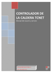
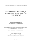
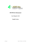
1
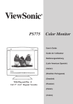
TCNet Boiler
Controller
User and Service Manual
Developed and assembled in Turkey.
Türkiye’de geliştirilmiş ve üretilmiştir.
TCNet Boiler Controller
User and Service Manual
Safety Instructions
Caution! Schock Hazard!
Risk of electrical schock which may cause serious injuries or death. Please
disconnect the mains before servicing this equipment.
Caution! Hot Surfaces!
The boiler assembly and/or the temperature sensors may be extremely hot!
Caution! Moving Parts!
Watch your hands while servicing the moving parts such as auger and grate
cleaning assembly which may cause serious injuries.
Caution!
This device is intended to be professionally installed. Incorrect installation and/or
operating parameters may cause dangerous conditions.
Please do not expose the control panel directly to
sunlight.
Please avoid any liquid contacts to control panel
and/or cable assemblies.
2
TCNet Boiler Controller
User and Service Manual
(This page is intentionally left blank)
3
TCNet Boiler Controller
User and Service Manual
Table of Contents
Safety Instructions ................................................................................................................................... 2
Overview to Control Panel ...................................................................................................................... 5
Quick Reference ...................................................................................................................................... 6
Starting and Stopping Your Boiler ....................................................................................................... 6
Setting up The Temperature of Boiler or Utility Water....................................................................... 6
Operation Menu ...................................................................................................................................... 7
Menu Structure ....................................................................................................................................... 9
User Preferences Menu........................................................................................................................... 9
Operation Mode ................................................................................................................................ 10
Weather Compensation .................................................................................................................... 10
Day-Night Compensation .................................................................................................................. 11
Date-Time .......................................................................................................................................... 12
Week Timer ....................................................................................................................................... 12
Internet Connectivity............................................................................................................................. 13
The Status Page ................................................................................................................................. 14
Adjust the Temperatures and Operation Mode From Internet ........................................................ 15
Setting up The Week Timer from Internet ........................................................................................ 16
Changing the Network Settings ......................................................................................................... 17
Turning On and Turning Off your Boiler From Internet .................................................................... 18
Clearing Errors From Internet ........................................................................................................... 18
Service Menu ......................................................................................................................................... 19
Boiler Setup ....................................................................................................................................... 20
Combustion Data ............................................................................................................................... 20
Ignition Data ...................................................................................................................................... 23
Circulation Data ................................................................................................................................. 23
Network Status .................................................................................................................................. 24
Pellet Refill......................................................................................................................................... 24
Digital Inputs ..................................................................................................................................... 25
Analog Inputs..................................................................................................................................... 25
Test Devices ....................................................................................................................................... 25
Factory Defaults ................................................................................................................................ 25
Error Log ............................................................................................................................................ 25
4
TCNet Boiler Controller
User and Service Manual
Overview to Control Panel
1.
2.
3.
4.
5.
6.
Power key.
Input key.
Menu navigation key.
Menu navigation key.
Decrease parameter key.
Increase parameter key.
5
TCNet Boiler Controller
User and Service Manual
Quick Reference
Starting and Stopping Your Boiler
Please hold the power key to either run or stop your boiler.
The power state will be highlighted when you press the power
key.
Setting up The Temperature of Boiler or Utility Water
Press the Input key to enter the Temperature Setup menu.
Press navigation keys to
highlight boiler temperature or utility
water temperature.
Press adjust keys to change
the temperature.
To return operation menu, navigate
to “<Return” with navigation keys and press Input key.
To jump User Preferences Menu, navigate to Next> and pres input key.
6
TCNet Boiler Controller
User and Service Manual
Operation Menu
The operation menu indicates current process values of your boiler. Large LCD display allows the
control panel to show almos all temperatures measured by sensors and the calculated output power.
1. Power state: Indicates the current power state of your boiler. When it set to RUN, boiler will
opeate if any heat demand. When it set to STOP, boiler will complete the current cycle of
process and jump to deflating and cleaning sequences immediately.
2. Flue Temperature: Indicates the flue gas temperature.
3. Output Power: Indicates the calculated output power of the boiler.
4. Status display: Indicates the current process of your boiler
- Ready/Idle: No operation or the boiler reached the set point temperature
- Flame check: In this state, boiler checks the sensor if any flame exists on the grate.
- Ignition: Boiler is performing ignition cycle.
- Heating: Boiler is in normal burning cycle.
- Cleaning: Boiler is either deflating the flame or cleaning the grate and internal flue gas
pipes.
5. Grate Display: In this are of screen, control panel shows the curent state of your boiler.
Idle/No operation
Flame check
Ignition Cycle
Boiler is operating at 20% or less of its rated power.
Boiler is operating at 20%-40% of its rated power.
Boiler is operating at 40%-60% of its rated power.
Boiler is operating at 60%-80% of its rated power.
7
TCNet Boiler Controller
User and Service Manual
Boiler is operating at 80%-100% of its rated power.
Boiler is either performing the deflating sequence or grate cleaning sequence.
6. Device Icons:
Auger is operating.
Blower is operating.
External fuel refilling system is operating.
I Ignition heater is operating.
C Cleaning mechanism is operating.
7. Utility water circuit status display:
water circuit.
This section indicates the measured temperature of the utility
icon indicates that the circulation pump of the utility water circuit is operating.
8. Building heating circuit status display:
This section indicates the building heating circuit’s data as same as
utility water circuit.
9. System clock in 24-hour format.
10. Measured weather temperature.
8
TCNet Boiler Controller
User and Service Manual
Menu Structure
TCNet controller has three menu schemes for quick setup, user preferences and the service settings.
The most common settings
are grouped together.
1. Temperature
Setup: Basic temperature
adjust of your boiler
2. User Preferences:
Operation mode, timer and
temperature compensation
options
3. Service Settings:
Advanced settings of your
boiler. This settings are
intended to be adjusted by
a service engineer.
User Preferences Menu
To enter the User Preferences menu, Press the
“Next>” with
Input key and navigate to
navigation keys than press the
input key again.
User Preferences menu has five settings.
9
TCNet Boiler Controller
User and Service Manual
Operation Mode
To change the operation mode press
adjust keys. Navigate to
<Return with
navigation keys
and press
Input key to return the
User Preferences menu.
There are three operation modes of your boiler.
Mode Building Heating
1
ON
Utility Water
ON
2
OFF
ON
3
ON
OFF
Both circulation pumps will operate according
to heat demand.
Only the utility water circuit’s circulation pump
will operate. (Summer mode)
Only the building heating circuit’s circulation
pump will operate. (Utility water is not
necessary or not available in the boiler system)
Weather Compensation
Your boiler is able to adjust the temperature setpoint according to the weather temperature.
To setup the weather compensation,
first navigate to temperature range
with
navigation keys and
select the temperature range with
adjust keys. After selecting
the temperature range, navigate to
Correction value and set the offset
temperature of your boiler for this
temperature range. To adjust another temperature range, navigate back to temperature range with
navigation keys and select the range that you want. After all settings have been completed,
navigate to <Return and press
Input key to return to the User Preferences Menu.
There are eleven temperature ranges for adjusting.
Range
-20 … -17:C
-16 … -13:C
-12 … -9:C
Adjust
-/+ 10:C
-/+ 10:C
-/+ 10:C
10
TCNet Boiler Controller
User and Service Manual
-8 … -5:C
-4 … -1:C
0 … 3:C
4 … 7:C
8 … 11:C
12 … 15:C
16 … 19:C
>20 :C
-/+ 10:C
-/+ 10:C
-/+ 10:C
-/+ 10:C
-/+ 10:C
-/+ 10:C
-/+ 10:C
-/+ 10:C
If the compensated temperature setpoint exceeds the temperature limits of the boiler, controller will
increase or decrease the setpoint in between minimum and maximum temperature limits.
Day-Night Compensation
Your boiler is olso able to adjust the temperature setpoint according to different time slices in a day.
To setup the day-night compensation,
first navigate to time slice with
navigation keys and select the
time slice with
adjust keys.
After selecting the time slice,
navigate to Correction value and set
the offset temperature of your boiler
for this time slice. To adjust another
time slice, navigate back to time slice
with
navigation keys and select the time slice that you want. After all settings have been
completed, navigate to <Return and press
Input key to return to the User Preferences Menu.
There are eight time slices to adjust.
00:00 – 02:59
03:00 – 05:59
06:00 – 08:59
09:00 – 11:59
12:00 – 14:59
15:00 – 17:59
18:00 – 20:59
21:00 – 23:59
If the compensated temperature setpoint exceeds the temperature limits of the boiler, controller will
increase or decrease the setpoint in between minimum and maximum temperature limits.
11
TCNet Boiler Controller
User and Service Manual
Date-Time
The controller panel has a realtime clock calendar.
To adjust the system time and date,
navigate to hour, minute, date,
month, year or day of week with
navigation keys.
Press
adjust keys to change. Controller
accepts 24-hour hh:mm time format
and dd/mm/yyyy date format.
Incorrect date setting may halt the
clock (i.e. 30/02/2011).
The realtime clock has a backup battery at the back side of the control panel. If your boiler resets the
date-time settings after AC mains power loss, replace the backup battery. The backup battery is
CR2032 type lithium battery. Please insert the battery with correct polarity. The overal life of backup
battery is about two years.
The chemistry of the battery may be harmful to the environment. Please dispose the old
battery properly according to the instructions on the battery’s package.
Week Timer
The week timer allows you to set three programs for each day of the week to turn on or turn off your
boiler.
To set up the week timer, first select
the desired day with
adjust
keys than navigate to ON/OFF
with navigation keys. If you select
OFF, all of three programs will be
ignored by the controller for that day.
Select the start-up and stop times
with
adjust the hour and minute with
<Return with
Menu.
navigation keys and
adjust keys. After all programs are completed, navigate to
navigation keys and press
Input key to return to the User Preferences
12
TCNet Boiler Controller
User and Service Manual
Internet Connectivity
The controller has an onboard Ethernet port to directly connect to the Internet or your local area
network.
The LAN connector of the boiler is depends on the boiler model. Please refer
to the instruction manual of your boiler fort he location of the LAN connector.
Use a straight patched network cable for connecting your boiler to your DSL
modem, router or computer.
The default IP address of your boiler is 192.168.1.127. If you have changed the IP address or enabled
the DHCP service, you may learn the controllers IP address from Service>Network Status menu.
To connect the control panel, your computer or device which has internet connectivity must be in
the same subnet.
Open your Internet browser software and type the IP address of your boiler.
If the network connection
is OK, you should see the
login window. The
username of the boiler is
“admin” and the password
is “boiler”
13
TCNet Boiler Controller
User and Service Manual
After login, you should see the status page of the boiler
The Status Page
All measured temperatures and the device status are shown on this page. CPU load indicates the
current utilization of the control panel’s processor.
14
TCNet Boiler Controller
User and Service Manual
Adjust the Temperatures and Operation Mode From Internet
Click the “Temperature Setup” on the menu box.
Adjust the temperatures and click “Submit” button.
If you don’t want to make any adjustments, click “Administration” from the menu and click the “Save
Settings to FLASH” button to make adjustmens permanent.
15
TCNet Boiler Controller
User and Service Manual
Setting up The Week Timer from Internet
Click the “Week Timer” on menu box.
Set up your desired start up and shut down times for each day.
If you don’t want to make any adjustments, click “Administration” from the menu and click the “Save
Settings to FLASH” button to make adjustmens permanent.
16
TCNet Boiler Controller
User and Service Manual
Changing the Network Settings
Click the “Network Configuration” on menu box.
Make all required changes on network configuration and click “Save Config” button.
Please note that the controller should reboot after changing the network settings and perform the
AC Power loss sequences at startup.
17
TCNet Boiler Controller
User and Service Manual
Turning On and Turning Off your Boiler From Internet
Click “Administration” on menu box.
Click “Turn On Boiler” button to turn on your boiler.
Click “Turn Off Boiler” button to turn of your boiler.
Clearing Errors From Internet
If you see any error messages on the status page, you may clear the error by clicking the “Clear
Errors” button on the Administration page.
18
TCNet Boiler Controller
User and Service Manual
Service Menu
Caution! This settings are intended to be adjusted by a well trained service
technician or a service engineer. Incorrect settings may cause dangerous
conditions.
To enter the Service menu, navigate to Service> with
and press
navigation keys
Input key.
Service Menu Structure
19
TCNet Boiler Controller
User and Service Manual
Boiler Setup
Max. Power kW
25
Min. Power kW
5
Feed rate gr/min
380
Efficiency %
91
Max auger Curr. A
0.5
Curr. Detect latency sec
2
Grate Open T s
190
The maximum power of the
boiler
The minimum power of the
boiler
The pellet feed amount for a
minute of the auger or other
fuel feeding system.
The total efficiency of the
boiler
The maximum allowable
current drawn by the auger
excitation motor.
The time delay for the auger
current limit alarm
The run time of the grate
open/close actuator.
Combustion Data
Fuel Energy kW/kg
4.88
Modulator
PID
Mod. Delta :C
10
Hysteresis :C
2
Feed Period :C
15
The energy of a kilogram of
used pellet. (Please refer to the
information on your pellet
package)
The power regulation metod of
the boiler. There are three
modes for power regulation.
(PID [Graph1], 5STEP [Graph2]
or fixed power [Graph3])
The power regulation to reduce
the power of the boiler.
Eg. : The boiler temp. 50 C
Mod.Delta : 10 C
Boiler begins to slow down
when it is reached to 40 C.
The temperature overlimit.
E.g :
The temp.of the boiler is : 50 C
If the hysteresis is set 2 C.
the boiler operates between
50-51 C. If it exceeds the 51 C
,it deflates the flame.
The fuel consumption to reach
the capacity :
E.g : If the feed period is set 15
it feeds 5 gr in every 15 sec.
If the feed period is set 20 it
feeds 7 gr.
If the feed period is set 25.
It feeds 9 gr.fuel in every 25 sec
20
TCNet Boiler Controller
User and Service Manual
Power and Fan speed settings for 5STEP modulation or Fixed power.
Mod1
Mod2
Mod3
Mod4
Mod5
Exh. Limit :C
5kW
10kW
15kW
20kW
25kW
Fan:
Fan:
Fan:
Fan:
Fan:
150
33
37
40
43
46
Maximum allowable flue
temperature. In case of flue
gases exceed the limit,
controller will reduce the
power to regulate the flue gas
temperature.
Graph 1 PID Modulation
21
TCNet Boiler Controller
User and Service Manual
Graph 2 5 Step Modulation
Graph 3 Fixed Power Regulation
Tuning the PID modulation:
-
If your boiler never reaches the setpoint, Increase the Mod1 Power level.
If your boiler exceeds the setpoint more than the hysteresis value, Decrease the Mod1
Power Level.
If your heating circuit(s) power demand is too low for the boiler (for example only utility
water heating in summer) you may decrease the Mod5 Power level to avoid overshoot
the temperature setpoint.
22
TCNet Boiler Controller
User and Service Manual
Graph 4 Feed Period
Ignition Data
Feed Time sec
Timeout min
Retries
Burn. Detect Temp :C
Burn. Detect Delta :C
Auger Filling min
First run
Fan Speed
60
10
3
100
7
3
0
50
[Graph5]
Graph 5 Burning Detection and Deflating Cycle
Circulation Data
Heating Circuit
Threshold
35
23
TCNet Boiler Controller
User and Service Manual
Hysteresis
2
Util. Water Circuit
Threshold
Hysteresis
35
2
Network Status
IP Address
192.168.1.127
Subnet Mask
255.255.255.0
Default Gateway
192.168.1.1
The IP address of the controller
The subnet mask of the controller
The default gateway address (DSL modem router
etc.)
Pellet Refill
Machine Type
Run duration (minutes)
None-> Auger -> Suction
10
The type of the refill system.
The run time of the refill
system in case of detection of
low pellet level from the
bunker.
24
TCNet Boiler Controller
User and Service Manual
Digital Inputs
IN0: OFF
IN1: OFF
IN2: OFF
IN3: OFF
IN4:OFF
IN5: OFF
IN6: OFF
IN7: OFF
The input signals of the
controller.
OFF : No signal / Open
ON: Signal / Close
Analog Inputs
T3 (boiler temp. Sensor)
LM (Lambda sensor)*
The measured values of the
Analog-to-digital converter of
T1 (Util. Water temp. Sensor)
PC (Photocell)*
the controller
T2 (Weather temp. Sensor)
TC (Flue temp. Sensor)
(*) Lambda sensor and photocell may not be implemented on your system.
Test Devices
Warning! This menu is only for testing the outputs of the boiler for a short time. Leaving
the boiler in Test Devices menu may cause dangerous conditions.
IGN
PUMPH
PUMPU
AUGER
CLEAN
REFILL
FAN1
FAN2
FAN3
Select the device with
navigation keys to test.
+ adjust key: RUN
_ adjust key: STOP
Factory Defaults
Restores all parameters to the Factory defaults.
Error Log
Controller stores the last five errors.
Record format is DD/MM/YYYY HH:MM – Error code
25