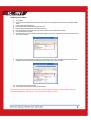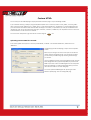
1
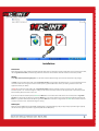
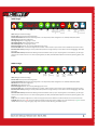
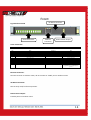
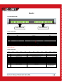
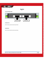
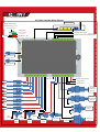
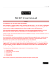
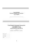
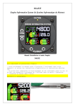
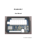
iDash User Manual
1
iDash Package Contents:
1x iDash unit
1x Wireless router
1x 4 wire iDash Power cable (4ft)
1x 2 wire wireless router Power cable (2ft)
2x 1 Amp replacement fuse
Software CD
*Lambda sensor, Lambda cable, 10 Amp replacement fuse, and mild Steele O2 bung, are included only if Lambda option is ordered
Testing Wireless Functionality:
It is a good idea to test the wireless functionality of your iDash unit before doing a full installation, so this is what we will do first.
Referring to Fig.2-iDash Left Side, connect the Red wire on the 4 pin Power Cable to 12[v] and the Black wire to ground, this will provide iDash
with power.
Referring to Fig.6-IDash Complete Wiring Diagram, connect the wireless router to iDash with the supplied ethernet cable and the supplied 2
wire Power cable. The ethernet cable should connect to the ethernet port marked with a “1” on the wireless router. Your iDash unit will supply
power to the wireless router through the 2 wire Power cable.
Power up iDash by apply 12v to the Red wire and Ground to the Black wire. Referring to Fig.4-iDash Front Side, the orange LED on the iDash
Ethernet connector should be light, this indicates that power for iDash and the wireless router is “ok” and also that there is a physical ethernet
connection between iDash and the wireless router.
The wireless router will automatically create an unsecured wireless network named “iDash”, with your tablet/smartphone/PC connect to the
“iDash” wireless network. In your browser enter “192.168.1.147” into the address bar, this will bring up the iDash homepage (see image
below). Once you are able to access the iDash homepage you can now begin a full installation.
2
Installation:
Placement:
iDash and the wireless router should be mounted inside the vehicle cabin. For the built in dual axis accelerometer to be accurate the Front Side,
refer to Fig.4-iDash Front Side, should be facing towards the direction of travel and iDash should be mounted as horizontal as possible.
Wiring:
Follow Fig.6-IDash Complete Wiring Diagram for an idea of the overall installation wiring. If you need more detail refer to Fig.2 to Fig.5.
The Black wire on the 4 wire Power Cable, refer to Fig.2-iDash Left Side, is the ground for the iDash electronics, it is a very important ground so
care must be taken to ensure a good connection. The best place to ground the Black wire is where your ECU is grounded or close to the
negative terminal of your battery.
The Red wire on the 4 wire Power Cable, refer to Fig.2-iDash Left Side should be connected to a 12[v] source that is “live” when vehicle
accessories power is “on” or when the engine is running. You do not want to directly connect it to the 12[v] terminal on your battery as it will
drain the battery when your vehicle is not in use.
If your iDash unit has the Lambda option, the Green and White wires on the 4 wire Power Cable needs to be connected, refer to Fig.2-iDash
Left Side. You need to take care where you ground the White wire, it carries large pulsed current and should be grounded far from where the
Black wire is grounded. Generally the best place to ground the White wire is the chassis or engine block. The Green wire should be connected
to a 12[v] source that is “live” only when the engine is running.
RPM Input:
iDash has a built in RPM pickup for Engine RPM, the RPM pickup is compatible with 0[v] to 5[v] or a 0[v] to 12[v] square wave signal. Typically
the low side of the ignition coil produces a signal compatible with the RPM pickup.
3
Wideband Oxygen sensor Installation (only if Lambda Option Purchased):
For all Oxygen sensor installations the sensor must be installed before the catalytic converter.
For normally aspirated engines the Wideband Oxygen sensor should be installed about 2ft from the engine exhaust port. For Turbocharged
engines the Wideband Oxygen sensor should be installed about 3ft from the engine exhaust port after the turbocharger. For Supercharged
engines the Wideband Oxygen sensor should be installed 3ft from the engine exhaust port. Installing the Wideband Oxygen sensor too close to
the engine exhaust port may overheat the sensor, installing the Wideband Oxygen sensor too far from the exhaust port may leave the sensor
too cool, both will cause damage to the sensor and lead to wrong measurements. iDash allows you to monitor the temperature of the
Wideband Oxygen sensor, if you notice the temperature is too hot or too cool you should change the location of the sensor.
The Wideband Oxygen sensor should be installed between the 10 o’clock and the 2 o’clock position, this will allow gravity to remove water
condensation from the sensor.
The Green wire on the 4 wire Power Cable supplies the heater inside the Wideband Oxygen sensor with 12[v] power, it is important that the
12[v] on the Green wire be “live” only when the engine is running. If the sensor is heated before the engine starts, condensation in the exhaust
system may move to the sensor and cause thermal shock to the sensor, if the sensor is left unheated in an active exhaust stream; carbon will
build up on the sensor and ruin the sensor.
iDash Usage:
iDash supports HTML, HTML5, and adobe flash. HTML is totally text based and is suitable for older devices with slower processors. HTML5 is
graphics based, it requires a modern device with fast processor running a browser that supports HTML5. Adobe Flash requires a modern device
with fast processor and supported by Adobe Flash.
iDash presents text and graphics through a built in webserver just like a “normal” website on the internet, there is no software to install for
display and configuration. For firmware updates, and viewing of saved datalogs; software must be installed onto a PC running the Windows
operating system.
iDash allows multiple devices to connect at the same time, you can mix and match upto different 5 devices at one time, you can also mix and
match HTML, HTML5, adobe flash across multiple simultaneously connected devices with the limitation that only one device can use the Adobe
Flash interface at a time. Refresh speed will drop with more devices connected, realistically 3 is the maximum number of devices you want to
connect at once before the refresh rate becomes noticeably slower.
Browser Compatibility:
For Windows machines; Google Chrome runs the smoothest and offers the best user experience, Firefox is a close second choice, Opera and
Internet Explorer offers the worst user experience. Be sure to use update your browser to the most recent version for the best experience
possible.
For devices such as tablets and smartphones, your browser choices are generally limited to what your device ships with. Between the HTML,
HTML5, and Adobe Flash interfaces you will be able to find a good user experience for your particular device.
4
HTML Usage:
Home
Previous Dash
Current Dash Selected
Next Dash
Add
Large
Gauge
Add
Medium
Gauge
Add
Small
Gauge
Remove
last Gauge
Save
current
Dash
Record to
iDash
memory
Download
iDash Memory
Home: Navigates to iDash homepage.
Previous Dash: Loads previous Dash configuration.
Current Dash Selected: Shows which Dash configuration is currently loaded, 3 Dash configurations are available; Dash0,Dash1,Dash2.
Next Dash: Loads next Dash configuration.
Add large Gauge: Adds a large gauge to screen.
Add medium Gauge: Adds a medium gauge to screen.
Add small Gauge: Adds a small gauge to screen.
Remove last gauge: Removes most recently added gauge from screen.
Save current Dash: Save current Dash configuration as a browser cookie. Cookies on your browser must be enabled for this feature to work.
Record to iDash memory: Datalog to memory onboard iDash, iDash has enough memory to store about 3 hours of datalogging @ 10 samples
per second.
Download iDash memory: Downloads the datalog stored onboard iDash memory to your computing device. For windows PC, you will “right
click” the icon and select “save as”. For other computing devices, the ability to download files depends on the device, Operating System, and
browser.
HMLT5 Usage:
Home
Previous Dash
Current Dash Selected
Next Dash
Add
Gauge
Remove
last Gauge
Save
current
Dash
Record to
iDash
memory
Download
iDash Memory
Graph
Draggable
Home: Navigates to iDash homepage.
Previous Dash: Loads previous Dash configuration.
Current Dash Selected: Shows which Dash configuration is currently loaded, 3 Dash configurations are available; Dash0,Dash1,Dash2.
Next Dash: Loads next Dash configuration.
Add Gauge: Adds a gauge to screen.
Remove last gauge: Removes most recently added gauge from screen.
Save current Dash: Save current Dash configuration as a browser cookie. Cookies on your browser must be enabled for this feature to work.
Record to iDash memory: Datalog to memory onboard iDash, iDash has enough memory to store about 3 hours of datalogging @ 10 samples
per second.
Download iDash memory: Downloads the datalog stored onboard iDash memory to your computing device. For windows PC, you will “right
click” the icon and select “save as”. For other computing devices, the ability to download files depends on the device, Operating System, and
browser.
Graph: Plots current Dash configuration as a Value vs Time graph. Some metrics will be auto scaled to make best use of screen real estate.
Draggable: When the pin is “red” colored this will automatically tile new gauges that are added to the screen. When the pin is “green” colored
this will allow the user to drag move gauges, drag move requires a browser with very good HTML5 support.
5
Adobe Flash Usage:
The Adobe Flash screen cannot be customized, it displays all the available metrics on screen at once. There are no controls on the Adobe Flash
screen.
Loading of the Adobe Flash screen can take upwards of 2 minutes for slower devices.
Available Metrics for Display and Datalogging:
Name
AFR1
LSU1T
AFR2
LSU2T
EGT1
EGT2
EGT3
EGT4
EGT5
EGT6
EGT7
EGT8
RPM
SRPM
MAP1
MAP2
FLT
IAT1
IAT2
FP
OP
GFY
GFX
Vin1
Vin2
DL
Full Name
AFR1
LSU1 Temperature
AFR2
LSU2 Temperature
Exhaust Gas Temperature 1
Exhaust Gas Temperature 2
Exhaust Gas Temperature 3
Exhaust Gas Temperature 4
Exhaust Gas Temperature 5
Exhaust Gas Temperature 6
Exhaust Gas Temperature 7
Exhaust Gas Temperature 8
Revolutions Per Minute
Shaft Revolutions Per Minute
Manifold Absolute Pressure 1
Manifold Absolute Pressure 2
Fluid Temperature
Intake Air Temperature 1
Intake Air Temperature 2
Fuel Pressure
Oil Pressure
Gforce Y axis
Gforce X axis
Voltage input 1
Voltage input 2
Datalog Status
Description
Air to Fuel Ratio measured by Wideband sensor 1
Temperature of Wideband sensor 1
Air to Fuel Ratio measured Wideband sensor 2
Temperature of Wideband sensor 2
Exhaust Gas Temperature measured by EGT probe 1
Exhaust Gas Temperature measured by EGT probe 2
Exhaust Gas Temperature measured by EGT probe 3
Exhaust Gas Temperature measured by EGT probe 4
Exhaust Gas Temperature measured by EGT probe 5
Exhaust Gas Temperature measured by EGT probe 6
Exhaust Gas Temperature measured by EGT probe 7
Exhaust Gas Temperature measured by EGT probe 8
Engine RPM
Shaft RPM
Boost/Vacuum sensor 1
Boost/ Vacuum sensor 2
Fluid Temperature
Intake Air Temperature sensor 1
Intake Air Temperature sensor 2
Fuel Pressure sensor
Oil Pressure sensor
Acceleration/Deceleration G Force
Cornering G Force
Analog Voltage Input 1
Analog Voltage Input 2
% of datalog memory full on iDash
Note
Requires Lambda Option Purchase
Normal temperature is 750[C] = 100%
Requires Lambda Option Purchase
Normal temperature is 750[C] = 100%
0[C] to 2500[F], 0[C] to 1400[C]
0[C] to 2500[F], 0[C] to 1400[C]
0[C] to 2500[F], 0[C] to 1400[C]
0[C] to 2500[F], 0[C] to 1400[C]
0[C] to 2500[F], 0[C] to 1400[C]
0[C] to 2500[F], 0[C] to 1400[C]
0[C] to 2500[F], 0[C] to 1400[C]
0[C] to 2500[F], 0[C] to 1400[C]
0[RPM] to 10000[RPM]
0[RPM] to 10000[RPM]
0[PSI] to 44[PSI], -30[Hg] to 88[Hg]
0[PSI] to 44[PSI], -30[Hg] to 88[Hg]
0[F] to 300[F], 0[C] to 150[C]
0[F] to 250[F], 0[C] to 125[C]
0[F] to 250[F], 0[C] to 125[C]
0[Hg] to 250[Hg], 0 to 150[PSI]
0[Hg] to 250[Hg], 0 to 150[PSI]
+ve = accel, -ve = Decel, -4[G] to +4[G]
+ve =Left turn, -ve=Right turn, -4[G] to +4[G]
0[v] to 5[v]
0[v] to 5[v]
There is enough memory for ~3hrs of storage
Sensor Calibration:
Some sensors need to be calibrated for maximum accuracy before using. Calibration is done through the Config.htm page. After you select the
type of calibration from the “Calibrate” drop down menu, press the “Save to iDash Memory” to perform the calibration.
Lambda Free Air Calibration: Using the known Oxygen concentration of Free Air, ~20.9%, you can calibrate the Wideband Oxygen sensor to
remove the effects of aging on the sensor. I do not recommend using Free Air calibration, it is only there because another brand of Wideband
controllers has made it a popular feature. As the Wideband sensor ages it only loses minor amounts of accuracy, more accuracy is typically lost
by users not following procedure than gained by users correctly following procedure. Follow the onboard screen prompt to ensure you have
properly performed the calibration procedure.
Lambda HW Calibration: This is for factory use only when installing a new Lambda module into iDash, end users should not use this.
EGT Calibration: Follow the onboard screen prompts to perform the calibration procedure.
MAP Calibration: Follow the onboard screen prompts to perform the calibration procedure.
Accelerometer Calibration: Follow the onboard screen prompts to perform the calibration procedure.
6
PC Software:
Software Installation:
Run “iDash_Deploy_x_xx.exe” from the included CDROM, this will start the windows software installation. This software is for the Windows
Operating System only. This will install 2 pieces of software; iDash Ethernet Bootloader and iDash Datalog Converter. You will also need to run
the “WINLOGSETUP_14Point7.exe” from the CDROM to install Winlog onto your computer.
iDash Ethernet Bootloader allows the updating of the iDash firmware via the Ethernet port.
The datalog file downloaded directly from iDash memory is compressed to conserve memory space on iDash and to reduce download time. The
iDash Datalog Converter will decompress the datalog file into a plain text format with each data field separated by a “,”. The decompressed file
can be read by a spreadsheet such as Microsoft Excel or by the included WinlogView datalog viewer.
Winlog is a 3rd party data visualization program, there are 2 software components to Winlog; Winlog which is a real-time data visualizer and
WinlogView which is a viewer for datalogs saved to disk. Because iDash already has real-time data visualizer via HTML, HTML5, Adobe Flash,
Winlog will not be used, but WinLogViewer will be used to view saved datalogs.
Firmware and Webserver Updating:
There are 2 software components to iDash; firmware and webserver. You can think of the iDash firmware as defining the function and the
webserver as defining the form or look.
Generally the firmware version on iDash has to match with the webserver version, you will be notified at the bottom of the Config.htm page in
red if there is a mismatch. If you do not see a warning message in red, then there is no mismatch.
Updating the Webserver:
At the bottom of the Config.htm page there is a link “Goto Webserver Update Page”, click the link. Browse to where the Webserver file holding
the update is and then click “upload”. This will take around 30 seconds to update.
After a firmware or webserver update you should clear your browser cookies and download a new set of settings to iDash; AFR Conversion,
RPM Multiplier, Pressure Units, etc…, you should also recalibrate your sensors.
7
Updating the Firmware:
1)
2)
3)
4)
5)
6)
7)
8)
9)
Turn off iDash
Unscrew the 4 screws holding the top lid of iDash, remove the lid. In the top right hand corner of iDash is a pushbutton labeled
“Reset”.
Power on iDash with the lid removed.
Run the “iDash Ethernet bootloader” program from your PC
Click the “File” button and browse to where the firmware file is
Click “Capture Target”, this will constantly send a firmware update request to iDash over the network.
Press the “Reset” button on iDash.
Once iDash is able to connect to the Ethernet Bootloader program, the status box will update with information similar to what is
seen in the picture below.
Click “Program” to begin the firmware update process, this will take about 1 minute to complete. Once the firmware update is
complete the status box will update with information similar to what is seen in the picture below.
10) Turn off iDash and secure the lid to iDash.
11) Power on iDash, now iDash will be running the new firmware
After a firmware or webserver update you may need to clear your browser cookies and download a new set of settings to iDash; AFR
Conversion, RPM Multiplier, Pressure Units, etc…, you may also need to recalibrate your sensors.
8
Custom HTML:
You can create your own HTML webpages to display information from iDash, doing so requires knowledge of HTML.
In your installation directory, probably “C:\Program Files\14Point7\iDash” there is a directory named “Custom_HTML”, in “Custom_HTML”
there is a directory named “HTML_Source”, in “HTML_Source” is a file named “Example.htm”. “Example.htm” is a simple webpage that gives
you all the essential code needed to fetch data from iDash and display it to a browser, it is expected that you make your modifications to the
“Example.htm” page. You can also edit the other htm pages; “index.htm”, “Html.htm”, “HTML5.htm”, and “Graph5.htm” but that is much more
involved and little or no code comments are available.
You can access the “Example.htm” page from the main screen through the
icon
Uploading Custom HTML files to iDash:
In the “Custom_HTML” directory there is a directory named “MPFS2”, in “MPFS2” is an executable “MPFS2.exe”, double click and run
“MPFS2.exe”.
The MPFS2 program will take webpages; compress them and upload it
to iDash.
Make sure your settings are the same as in the picture to the left and
click the “Generate and Upload” button, once the upload is complete
you can browse your HTML changes by connecting to iDash through
your browser.
There is 1 Megabyte of memory reserved for webpage storage, the stock
iDash webpage files take up approximately 600kb, so you have around
400kb of space to be creative. The MPF2Img2.bin file is the compressed
file of all the webpages, it is what gets uploaded to iDash, you should
check the file to make sure it is under 1 Megabyte.
You can also upload the MPFS2Img2.bin file by clicking the “Goto
Webserver Update page” link in the “Config.HTM” page.
9
RPM pickup:
For some RPM signals to read correctly and without noise, you may need to change the variable resistors on the iDash PCB. Open the iDash
enclosure, near the bottom center are two variable resistors, “RPM_Threshold” and “RPM_Hysteresis”. The default variable resistance
positions (default from 14Point7) will work for most RPM pickups. If iDash is not displaying RPM correctly, or if the reading is erratic then you
may need to adjust those variable resistors.
Variable Resistor-Min Position
Variable Resistor-Normal Position (default from 14Point7)
Variable Resistor-Max Position
Turn the variable resistor clockwise to go from Min Position to Max Position.
RPM Pickup Adjustment Procedure:
•
•
•
Set Both the RPM_Threshold and the RPM_Hysteresis variable resistors to the Min Position.
Slowly adjust the RPM threshold variable resistor clockwise towards the Max Position, stop when the RPM displayed by iDash is
correct. At this point the RPM readings may be erratic or noisy, that is taken care of by adjusting RPM_Hysteresis.
Slowly adjust the RPM_Hysteresis variable resistor clockwise towards the Max Position, stop when you notice that the RPM signal is
smooth enough to your liking.
You may need to go back and forth a few times between both variable resistors for the RPM to read correctly and smoothly. If you notice that
as you add more Hysteresis that the RPM displayed by iDash becomes incorrect or drops to 0; you will have to turn the RPM_Threshold variable
resistor a bit more clockwise towards max until you get the correct reading and then continue adjusting RPM_Hysteresis to remove noise.
10
Known Problems and Bugs:
If you save large dash configurations as browser cookie, this will bring up a “414 Request-URI Too Long: Buffer overflow detected” or “Data
expected but not there” error in your browser. The browser cookie gets transmitted to iDash each time a request for data is made to by your
browser, this is because all webservers are stateless machines and have no memory of the past so it relies on the browser cookie sent to it by
the browser to keep track of the past. If the browser cookie is too large it will overflow the memory buffer on iDash. To correct this error you
need to clear your browser cookies through your browser settings or use the “Clear All Cookies” button in the“Config.htm” page.
HMTL5 and the Adobe Flash interface are optimized for an AFR conversion of 14.7 for gasoline. Changing the AFR Conversion may result in the
AFR gauges looking awkward and unreadable. This does not affect the HTML interface.
On Apple devices, the last gauge in your saved dash configuration will not be correct, the workaround is to save an extra “dummy” gauge and
then delete the “dummy” gauge once the dash loads.
In some browsers the click dragging of gauges is not very precise.
Warranty:
14Point7 warrants this product to be free from defects for 2 years. Sensors if purchased from 14Point7 carry no warranty whatsoever.
Warranty does not cover user error and abuse.
Disclaimer:
14Point7 is liable for damages only up to the purchase price of its products. 14Point7 products should not be used on public roads.
11
Fig.1–iDash Top view
Front
Left
Right
Back
12
Left:
Fig.2-iDash Left Side
Power
Connector
Lambda
Sensor 1
Connector
Lambda
Sensor 2
Connector
Power Connector:
4
3
2
1
Pin #
1
2
3
4
Wire Color
Red
Black
Green
White
Name
System Power
System Ground
LSU Heater Power
LSU Heater Ground
Connects to
Switched 12[v]
Ground
Switched 12[v]
Ground to engine block or chassis
Note
“Switched” means 12v available only when engine is running
Make sure this is a solid ground.
Required only if Lambda module installed
Required only if Lambda module installed
Lambda Sensor 1 Connector:
If your iDash unit has Lambda module 1 installed, this connector connects iDash to Lambda sensor 1 via
supplied Lambda cable.
Lambda Sensor 2 Connector:
If your iDash unit has Lambda module 2 installed, this connector connects iDash to Lambda sensor 2 via
supplied Lambda cable.
13
Front:
I2C Barrel Connector
Fig.4-iDash Front Side
Screw Terminal A
Router Power Output
Ethernet
Connector
Screw Terminal A:
Pin 1
Pin #
1
2
3
4
5
6
7
8
9
10
11
12
Pin 2
Pin 3
Pin 4
Pin 5
Name
Not currently used
Not currently used
Not currently used
Not currently used
Not currently used
Not currently used
Not currently used
Not currently used
Not currently used
Lambda 2 Simulated Narrowband Output
Lambda 1 Simulated Narrowband Output
Lambda 2 Linear Output
Pin 6
Pin 7
Pin 8
Connects to
Stock ECU if required
Stock ECU if required
ECU/Datalogger
Pin 9
Pin 10
Pin 11
Pin 12
Note
for future expansion
for future expansion
for future expansion
for future expansion
for future expansion
for future expansion
for future expansion
for future expansion
for future expansion
0[v] to 1[v] output, switch point @ Lambda=1
0[v] to 1[v] output, switch point @ Lambda=1
0[v]@0.68[Lambda] linear to
5[v]@1.36[Lambda], equivalent to
0[v]@10[AFR] linear to 5[v]@20[AFR] for
gasoline
Ethernet Connector:
Connects to Port1 on wireless router, do not connect to “WAN” port on wireless router.
I2C Barrel Connector:
Not currently used, for future expansion.
Router Power Output:
Provides power to wireless router.
14
Back:
Fig.3-iDash Back Side
Screw Terminal B
Screw Terminal C
Screw Terminal B:
Pin 1
Pin 2
Pin #
1
2
3
4
5
6
7
8
9
10
11
12
Pin 3
Pin 4
Pin 5
Name
EGT 1 Positive
EGT 2 Positive
EGT 3 Positive
EGT 4 Positive
EGT Common Negative 1
EGT 5 Positive
EGT 6 Positive
EGT 7 Positive
EGT 8 Positive
EGT Common Negative 2
Map Sensor Input 1
Map Sensor Input 2
Pin 6
Pin 7
Pin 8
Pin 9
Pin 10
Connects to
14Point7 EGT Probe Red wire
14Point7 EGT Probe Red wire
14Point7 EGT Probe Red wire
14Point7 EGT Probe Red wire
Common Negative for EGT Probe 1-4, Blue wire
14Point7 EGT Probe Red wire
14Point7 EGT Probe Red wire
14Point7 EGT Probe Red wire
14Point7 EGT Probe Red wire
Common Negative for EGT Probe 5-8, Blue wire
14Point7 MAP Sensor White wire
14Point7 MAP Sensor White wire
Pin 11
Pin 12
Note
*
*
*
*
*
*
*
*
*
*
Optional
Optional
* Only “ungrounded junction” or “exposed junction” type EGT Probes can be used, using “grounded junction” type will damage iDash and
void your warranty!
Screw Terminal C:
Pin 1
Pin 2
Pin 3
Pin 4
Pin 5
Pin 6
Pin 7
Pin 8
Pin 9
Pin #
1
Name
RPM Input
Connects to
RPM input, tachometer or low side of ignition coil
2
3
4
5
6
7
8
9
10
11
12
Shaft RPM sensor Input
Fluid Temperature sensor Input
Air Intake Temperature sensor input 1
Air Intake Temperature sensor input 2
Fuel Pressure sensor input
Oil Pressure sensor input
Analog Input 1
Analog Input 2
Sensor Common Ground
5v Output
Lambda 1 Linear Output
14Point7 Shaft RPM sensor Blue wire
14Point7 Fluid Temperature sensor
14Point7 Air Intake temperature sensor Yellow wire
14Point7 Air Intake temperature sensor Yellow Wire
14Point7 Fuel Pressure Sensor
14Point7 Fuel Oil Sensor
14Point7 Shaft RPM Sensor Red wire
ECU/Datalogger
Pin 10
Pin 11
Pin 12
Note
RPM input, tachometer or low side
of ignition coil
0-5[v] only
0-5[v] only
Not currently used
Optional
0[v]@0.68[Lambda] linear to
5[v]@1.36[Lambda], equivalent to
0[v]@10[AFR] linear to
5[v]@20[AFR] for gasoline
15
Right:
Fig.5-IDash Right Side
RS232 Client
RS232 Host
RS232 Client:
Not currently used, for future expansion.
RS232 Host:
Not currently used, for future expansion.
16
Wireless Router
Engine block Ground /
Chassis Ground, required
only for Lambda
Ground
4
3
Switched 12v,
required only for
Lambda
2
1
Switched 12v
Lambda 2 Linear Output
Lambda 1 Simulated Narrowband Output
Lambda 2 Simulated Narrowband Output
Lambda Sensor 1
Lambda Sensor 2
Lambda 1 Linear Output
RPM Input
Analog Input 2
EGT 1
Analog Input 1
EGT 1
Air Intake
Temperature
Sensor 2
EGT 1
EGT 1
Ground
EGT 1
Air Intake
Temperature
Sensor 1
EGT 1
Ground
EGT 1
Oil Pressure
Sensor
EGT 1
White
White
Ground
12v
Ground
Ground
12v
Ground
MAP
Sensor
MAP
Sensor
Shaft RPM
Sensor
Fluid Temp
Sensor
Ground
Fuel Pressure
Sensor