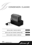
1
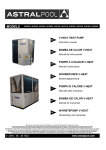
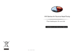
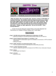
Air To Water Heat Pump
Thanks for Your Choice
MODEL: YASBP-78HL
YASBP-95HL
Air To Water Heat Pump
1. Safety Precautions
1
2. Packing List
2
3. Structure
4. Specifications
3
5. System Drawing
6. Installation
4
7. Controller
8. Maintenance
5
6
11
18
9. Trouble Shouting
19
10. Wiring Diagram
21
Air To Water Heat Pump
Air To Water Heat Pump
2.Packing list
3.Structure
● Outer Structure
Please verify that the following listed accessories are included in the
packaging.
If they are damaged or lost, please contact your local distributor or agent
immediately.
+
H
3
4
5
6
Installation & instruction manual:
7
It include basic product information,
guidance of proper usage methods
and maintenance.
X1
1
2
L
Water drainage pipe(1m)
X1
Drainage connection
Only horizontal discharge units have
it to connect the drainage pipe and
bottom plate.
X1
Anti-vibration rubber pads:
Put it under the four installation points
to reduce the vibration and noise produced during operation.
X4
Expansion screws:
Install it on the four points of the bottom
plate to fix the unit to the foundation.
2
X4
W
Only horizontal discharge units have
water drainage pipe to drain out the
condensed water from the bottom plate.
1. Fan and Motor
2.Maintenance Door
3.Wire Controller And
Waterproof Box
4.Water Outlet
5.Pressure Gauge
6.Power Supply
7.Water Inlet
Model
YASBP-78HL
YASBP-95HL
3
Demension
L
W
H
1010
370
615
1110
460
687
Air To Water Heat Pump
Air To Water Heat Pump
4.Specifications
5.System Drawing
Model
YASBP-78HL
YASBP-95HL
Heating capacity
KW
7.3
9.3
Heating power input
KW
2.1
2.3
Power supply
V/Ph/Hz
220/1/50
220/1/50
Rotary
Scroll
Compressor type
Compressor quantity
Fan power input
KW
Fan quantity
1
1
0.12
0.12
1
1
Fan Speed
Rpm
670
670
Noise level
dB[A]
54
58
Water Flow Volume
m3/h
1.5
2
Water connections
Inch
1
1
Water Pressure Drop
Kpa
Refrigerant
Unit dimensins(L/W/H)
mm
24
24
R410a
R410a
1010*370*615
1110*460*687
Defrost Mode
Evaporator
Measurement conditions:
Condenser
Outdoor air temp: 7℃/6℃,Inlet/ Outlet water temp: 40℃/45℃
Thermostatic
Expansion Valve
Filter
Filter
4
5
Air To Water Heat Pump
Air To Water Heat Pump
6.Installation
6. 1.The unit installation instruction
1. Please read the manual carefully before installation.
2. The installation location should be convenient for adjusting and repairing.
Enough space should be left for checking and repairing the unit.
3. The installation location should be far away from the places affected by
artificial strong electricity, magnetic field.
4.The unit should be installed in the indoor environment; if it is installed
outside environment, it is a must to built a cover for it.
5.There is no water flow switch when ex-works,if user need it, they should
install water flow switch by themselves. a water flow switch output has been
left on the controller , but two terminals of water flow switch were connected
when ex-works. so water flow switch alarm will not happen.
6.The vibration damping device should be installed to prevent the vibration
from the building.
7. Flexible connection must be used on water inlet and outlet, water
system supply and returned pipe. So is the recycle water pump, which
prevents vibration from spreading to the building.
8. Y - style filter should be installed on the water pump inlet of evaporator
and condenser to prevent the welding slag and the impurity from destroying
the unit.
9. An air discharge valve must be connected at the top of the water system
and drainage valve must be installed at the bottom of the water pipe of the
unit.
10. Please install the water pressure gauge and thermometer to make
care and maintenance easy.
11.The water pipe should be insulated well in order to prevent the energy
from losing and forming condensed water.
6.3.Lifting the unit
6.4.Space for installation
>40 0 mm
>5 00m m
Air inlet
>50 0 m m
Air outlet
>3 50 m m
6.2.The unit installation precaution
1. Please install the air discharge valve on the top of the water system.
2. Install the appropriate drainage valve at the bottom of the water system.
3. Be equipped with the expansion water tank to adapt the changing water
volume because of the changing water temperature in water system.
4. It is better for recycled water to use the softening water tap.
5. The bypass pipe should be reserved on the water supply pipe and
returned water pipe in order to wash the unit easily and avoid the melting
slag and impurity going into heat exchanger.
6. When connecting the pipe, absolutely don't permit to interchange the
outlet and inlet of the evaporator and condenson.
7. The water flow in evaporator and condenser should be the same as the
marked; absolutely prohibit from exchange water outlet and inlet, or the
unit will not run even will be destroyed.
8. The repairing and insulation of Y-style filter should made to be split
one, which is convenient to wash and repair for the system
9.Regarding to the water system, advise the client to check it every month.
6
6.5. Space for installation
1.The outdoor unit can be installed beside the balcony, on the roof, on the
ground or any other places where is convenient of installation and can
bear the weight of the unit.
2.a ventilated place
3.no heat radialization or other heat resource place
4.need to build a anti-snow shed
5.enough space should be left around the outdoor unit
6.no barrier beside the air inlet and air outlet
7.no strong wind at the air inlet
8.there should be drainage pipe for condensate draining
9.hot water tank should be install where running water is provided or near
to using side.
7
Air To Water Heat Pump
Air To Water Heat Pump
NOTE: It should be installed where can bear the weight of the unit and can
insulate noise and vibration.
If the unit is in a bad operating condition, such as in a place be of oil
-resource or poor water quality. This may lead to breakdown
6.8. Electric circuit connection processure.
1. see the follow figure, take off four screws from the maintenance panel and then
take off the panel as the instruction figure do.
6.6. Water pipe connection
1. The resistance of water pipe should be decrease as possible as we can.
2. All the pipeline should be clean, no rust dreg, avoid blocking the pipe. When
finished all the pipe and you should test all the water pipe work well. No leaking
and then pack insulation materials
3. Note: ductwork pressure testing should be made alone, it is not allowed to test
together with the unit
4. Expansion tank should be installed at the top of ductwork, the water surface in
the expansion tank need to be higher by 0.5m than the top of ductwork.
5. Water outlet outside the unit should install water flow switch, ensure that there
is water in the pipe when the unit are running. Controlling line of the water flow
switch should connect to terminal blocks accordingly into the control box, and
to be control together with the unit
6. It should be avoided that air lies in the water pipe, at the top of the pipe, it
should install a auto drain tap
7. By the side of water inlet and water outlet, thermometer and pressure gauge
should be installed, so that it will be check easily during the operation.
6.7 System installation drawing
Automatic
drain valve
Hot water outlet
B
C
2. Go in for the operation of wiring connection. Wring the connector of power
line under the unit loosely, then thread the power line through the connector
and enter into the unit. at last, wring the connector tightly. See the follow figure
B
3. Thread the power line through a rubber jacket under electrical box and to the
inner electrical box. See the follow figure.
Heat pump
Water tank
Cold water inlet
Pressure gauge
Thermometer
Bypass
sewage valve
Water flow switch
Soft connection
Valve
Check valve
Sewage valve
Water pump
4. Connect the power lines to the terminals according to the fixed phase. Live
line connect “L”, neutral line connect “N”, earth line connect “
”.See the
follow figure .
Terminal on water pump
Expansion
Y-style filter water tank
Attention: the pictures above is only for reference, the practical project must be
carried out by professionals according to the standard and design requirement.
8
Terminal on main power
9
Air To Water Heat Pump
Air To Water Heat Pump
7.Controller
5. If water pump is required, connect the water pump power line to the right
terminal in the electrical box. (note: water pump rated current <3A; if current
≥3A,must use AC contactor ).
The unit can be pre- programmed by the wire controller and will
then be run automatically.
6. After verifying the connection is right, the power can be on.
6.1 The appearance of wire controller and its key functions
Operation parameter
sequence
6.9. Run the unit
1.Check it before start the unit.
Check the piping system: check whether all the valve is open and the valve of
automatic control gorge is in a regularly range. Check whether the insulation
of pipes is good.
Check the power supply system: check whether the voltage is regular, any
parts are screwed tightly and the power is supplied as the wiring diagram.
Check whether ground line is connected well.
Check the unit: check whether all the screw on the unit is loose.
When switch on, check whether there are indicator malfunctions on main
control.
Connect the pressure gauge to the freon connection in order to measure the
system pressure when running the unit.
2.Try to run the unit
The compressor will start. Check whether the unit sounds unregularly by
hearing, switch off and check if it has. If it doesn’t have, keep it running, at the
same time pay attention to whether the cooling system pressure is regular.
And then check whether the power input and current corresponds to the
performance data in user manual. If not, please stop to check it.
The remote controller parameter has been set when ex-factory, don’t
adjust it at random. And it should be adjusted by professional personnel if
needed.
Regarding to the several connected modular units, the technical parameter
should adjusted by professional construction personnel.
3.Running
The following rules should be followed strictly when running the unit:
When the unit is running, keep the piping system and environment in a regular
state.
The sudden change of system and the environment can cause the motor
current change, When serious, it can exceed the rated current and can cause
negative consequences.
Ambient
temperature
Heating mode
Inlet temperature
Auxiliary electrical
heating
Data set mode
Outlet temperature
SET
Temperature displaying
mode
IN
ROOM
NO.
OUT
Data and error
number
TEMP
LCD Srceen
MIN
MIN
C
C
Start auxiliary
electrical heating
On/off switch
AUX
Change mode(This unit
will start under the
default mode.when
nothing is selected.)
Press these buttons separately to
scroll through water in, water out, coil
and outdoor air temperature .
Use this button and < >< >
button to set running parameter.
Press this button once to get you
into“set” parameter manual. Press
< > and < >button to increase or
decrease the data value.
Press <SET> button twice to
change to another parameter .If
no button is pressed for in 5
seconds, the screen will return to
the main manual.
6.2 Application range.
This intelligent wire controller can be used to control the air-cooled heat pump series. By
using it, you can choose single compressor system or two compressors system.
6.3 Initialization and standby state.
Initialization
IN N O .
SET
ROOM
OUT VALVE
MIN
HUM
ROOM
h
h
TEMP
TEMP
MIN
%
%
C F
C F
1
2
FAN AUTO
C
ON
OFF
Standby
M
SET AUX
M
Graph1-1
10
SET AUX
Graph1-2
11
Air To Water Heat Pump
Air To Water Heat Pump
current running mode.
7.4 Press ON/OFF button to turn on/off the heat pump.
ROOM
a. In the standby mode, press “SET” button to enter into the parameter setting page.( as
graph 4-1 shows)
b. Press“ ”or“ ”button to set the parameters. “00” stands for the water inlet temperature
setting in cooling mode. as the graph4-2 shows, “12 ℃” is real water inlet temperature.
c. After setting the water inlet temperature, press “SET” button to turn to the next setting
page.“01” stands for the water inlet temperature setting in heating mode. as the graph43 shows, “27 ℃” is real water inlet temperature. And press“
”or“
”button to choose
parameter you want
d. The screen will return to main page if you don't press any button within five seconds and
the screen display the water inlet temperature or water outlet temperature in the ON state
or environmental temperature in the OFF state.
f. In the ON state, you can see the current data of all kinds of parameters, but you can not
change it.
TEMP
M
C
ROOM
TEMP
SET AUX
C
Graph2
7.5 Mode selection.
SET AUX
M
C
a. In the ON or standby state, press“MODE”button to choose the heating or cooling mode
as the graph3-1 and 3-2 shows.
C
NO.
b. In the ON state the wire controller can display water inlet temperature, water outlet
temperature and its running mode
Parameter 00 : Water inlet
temperature during cooling
mode
Graph4-1
IN
OUT
IN
C
M
C
C
SET AUX
M
NO.
OUT
Heating
OUT
Parameter01: Water inlet
temperature during heating
mode
AUX
C
Graph4-3
SET AUX
7.7 Other parameters setting.
Graph3-2
Graph3-1
:this symbol is meant to be in a heating mode.
:this symbol is meant to be in a cooling mode.
the swimming pool heat pump parameter default setting is in the single heating mode, so as
long as you press the
button, the heating symbol will appear.
12
AUX
Graph4-2
C
VALVE
C
c. In the OFF state, the wire controller environmental temperature and current running
mode.
Cooling
C
b. In the standby state, the wire controller displays the environmental temperature and the
7.6 Temperature setting.
C
C
a. When you turn on wire controller, it will display the data full screen. Meanwhile, the wire
controller will get a communication connection with the heat pump. If the connection can
not be successful within ten seconds, that is to say, the connection failed. The heat pump
can only be control by its own emergency switch. On the contrary, if the connection can
be successful within ten seconds, the wire controller can also work as well as the heat
pump's own emergency switch.
13
Air To Water Heat Pump
Air To Water Heat Pump
NO.
VALVE
Parameter 08: Model
“0" stands for cooling only
“1" stands for heating and cooling machine
“2" stands for electrothermal machine
“3" stands for heating only
AUX
Graph5-7
7.8 Parameters display.
Parameter 02:
Defrosting cycle
NO.
VALVE
VALVE
MIN
AUX
NO.
C
Parameter 03: Initial
defrosting temperature
a. In the “ON” or “OFF” state, press “ ”or“ ”button, you can see all kinds of temperature
parameters.
b. You can see the water inlet/ outlet temperature, defrosting temperature sensor
1,defrosting temperature sensor 2 and environmental temperature.
c. If you don't press any button within five seconds, screen will return to main page and
display water inlet/outlet temperature in the “ON” and display the ambient
temperature in the “OFF” state.
AUX
OUT
IN
Graph5-1
Graph5-2
C
NO.
Parameter 04: Final
defrosting temperature
VALVE
NO.
VALVE
MIN
C
AUX
Parameter 05: End time
of defrosting
Graph5-3
NO.
AUX
C
C
C
a. In the standby state, press “SET” button to enter into parameters setting page as the
graph 4-1 shows.
b. Press “
”and“ ”button at the same time, when you hear “tick” sound, release the
buttons and press “
”or“
”button again to set the current page parameter as
graph 5-1 shows.
c. After setting it, press “SET” button to enter another parameters setting page, press
“
”or“
”button to set the parameter of the current page.
d. Repeat the above steps to alter other parameter setting. The screen will return to main
page if you don't press any button within five seconds and the screen display the water
inlet temperature or water outlet temperature in the ON state or environmental
temperature in the OFF state.
f. In the ON state, you can see the current data of all kinds of parameters, but you can not
change it.
Water inlet/outlet
temperature
C
C
AUX
Defrosting temperature
sensor 1
Graph6-1
AUX
Graph6-2
Graph5-4
VALVE
Parameter 06:
Number of system:
“1" stands for single system
“2" stands for double system
Defrosting temperature
sensor 2
VALVE
Parameter 07: Power
down memory function:
“0" stands for on
“1" stands for yes
Graph5-5
C
C
NO.
AUX
AUX
AUX
Ambient temperature
Graph6-3
AUX
Graph6-4
Graph5-6
14
ROOM
15
Air To Water Heat Pump
Air To Water Heat Pump
7.9 Fault and protection
Fault PP03:
Fault in defrosting
temperature sensor 1
a. When E1, E2, E3, E4, E8 faults happened, the wire controller will display fault code
accordingly. As the graphs show:
Fault EE01:
Fault in system 1
Fault PP04:
Fault in defrosting
temperature sensor 2
Graph8-3
AUX
Fault EE02:
Fault in system 2
Graph7-1
Graph8-4
Fault PP05:
Fault in ambient
temperature sensor
Graph7-2
Fault EE03:
Water flow fault
Fault EE04:
High/Low pressure
fault function
Graph7-3
Graph8-5
Graph7-4
Fault EE08:
Fault in communication connection
7.10 Defrosting
1 The condition of the entrance to defrosting.
When the unit heating continuously for 40 minutes, and condenser is frosting, at that
time, the defrosting system will run as long as Tp1(coil temperature ) ≤-3℃. As the
parameter 03 showed (Parameter 03 symbolizes coil temperature.
2. The condition to quit from defrosting.
When the Tp1( coil temperature)>13℃ or defrosting time get to 8 minutes. The
system will quit from defrosting.
7.11 Defrost process
Graph7-5
b. When P1, P2, P3, P4, P5, P7 protection take place, wire controller will display the
protection code accordingly. As the graphs show:
Fault PP01:
Fault water inlet
temperature sensor
Fault PP02:
Fault water outlet
temperature sensor
Graph8-1
1.The following process will happen when the defrosting condition is satisfied.
1) Compressor and outdoor fan stop.
2) 25 seconds later, four-way valve power off.
3) 30 seconds later, compressor will run
4) Water pump run normally..
2.When the exist condition of defrosting is satisfied, the following process will happen.
1) When the exist condition of defrosting is satisfied, defrosting stop, and compressor stop
running accordingly, but the outdoor fan start to run, 5 seconds later, four- way valve
power on.
2) After the fan run for 30 seconds, the system will recover to heating normally.
Graph8-2
16
17
Air To Water Heat Pump
Air To Water Heat Pump
7. Maintenance
8.
9. Trouble shouting
9.1
Failure
Possible causes
1. Power source failure
Before doing any maintenance cut off the power supply of the machine.
[1] Air Passage
To clean the air passage, take off the sound absorption hood and remove leaf and
dirt from the evaporator and air way. Clean the evaporator from dust, to keep it`s
performance high. There are two ways of cleaning the evaporator.
(1) Choose a detergent which is available in specialised trade and follow the
instructions of it`s user manual. Spray the detergent between the fins of the
evaporator, wait the stated time and wash it out with tap water.
(2) Use a pressure washer to clean the fins from dust.
Note: The fan can stand splash water. Be very cautious during washing the thin
fins, they can be easily bend.
[2] Water Cycle
To assure sufficient water flow volume, wash (or change) the water filter
regularly, depending on the pureness and the amount of the heating-circuit
water. To wash the water circuit inside the machine, choose a specialist company
to do the maintenance.
Avoid frozen water in the water cycle at any time, to prevent the water
components from cracking. When the ambient temperature lowers to less than
2℃ the heat pump must be switched on, to avoid freezing.
If the machine is switched off or there is a electrical power outage, the water has
to be drained to protect the system. There for open the drainage valves inside the
building to drainage the connection pipes. Open the circulation water drainage at
the heat pump. Open the drain screw below the water pump inside the heat pump.
Close the drains after all water went out.
[3] Disposal
To dispose the heat pump refer to the local regulations. Especially take care for
disposing the refrigerant and the compressor oil.
18
No running of the unit
The pump is running
without water
recycling or with high
noise
2. Loosened wiring
3. The power fuse has broke
1. Water leakage of the water
system
2. There is air in the system
3. the valves are not open
entirely
4. Filter blockage
Solutions
1. turn off the switch and
check the power source
2. find the caused and repair
3. change a new fuse
1. check the water supply
device and inject water
2. Discharge the air
3. open the valves completely
4. Wash the filter
1. check leakage and supply
1. refrigerant shortage
refrigerant
Low refrigerant capacity
2. bad water thermal insulation 2. Improve the insulation
while
3. bad heat elimination of air
3. wash the heat exchanger
compressors are running
heat exchanger
and improve condensing
4. Water flow shortage
4. Wash the filter
1. discharge unwanted
1. Excessive refrigerant
Over-high outlet
refrigerant
pressure of compressors 2. Bad heat elimination of air 2. Wash the heat exchanger
heat exchanger
and improve condensing
1. check leakage and supply
1. refrigerant shortage
refrigerant
2. filter or capillary blockage
2. change new filter or capillary
Over-low inlet pressure
3. wash the filter or discharge
of compressors
3. water flow shortage
the air in the system
4. Capillary in the expansion
4. change the expansion valve
valve cracks
1. examine the power source
1. power source failure
and eliminate the failure
2. compressor contactor
2. change the contactor
failure
3. loosened wiring
3. check and repair it
No running of
4. Compressor over loading
4. compressor over loading
compressors
protection
protection
5. wrong setting for inlet water
5. Reset it
temperature
6. Wash the filter or discharge
6. Water flow shortage
the air in the system
19
Air To Water Heat Pump
Air To Water Heat Pump
10. Wiring diagram
FAN
PUMP
AUXHEATER
R1 water inlet sensor
R2 water outlet sensor
R3 coil sensor
R4 ambient sensor
KM1 comp AC contactor
K1 pump relay
K2 fan relay
A1 main control board
A2 line controller
F1 pressure switch-low
F2 pressure switch-low
M1 compressor
M2 fan motor
V1 4 way valve
T1 To power supply
R4
R1R2 R3
A1
N
4-WAY VALVE2
F1 F2
SET
2. water switch damage
1. wash the filter or discharge
the air in the system
2. Change the switch
4-WAY VALVE1
A2
1. water flow shortage
2. Reset the temperature
COMP2
M
Low water flow
protection
2. Low setting value on
temperature
COMP1
AUX
CHILLER-300
Low water temperature
protection
1. water flow shortage
N N
The compressors are
running, but the unit
is not cooling/heating
MODEL: EARW085TTRF
L
No running of fan
motors
Solutions
1. Check the cause and
eliminate it
2. change the compressor
1. change the relay
2. change the fan motor
1. examine leakage and supply
refrigerant
2. change the tube-in-tube heat
exchanger
3. Change compressors
1. Wash the filter or discharge
the air in the system
V1
High noise of
compressor
Possible causes
1. Liquid refrigerant into the
compressor
2. compressor crash
1.Relay failure
2. fan motor destroyed
1. completely leakage of
refrigerant
2. Tube-in-tube heat exchanger
ruined
3. Compressors fault
KYOUT
MDOUT
GND
NET
GND
12V
KYIN
MDIN
GND
WATER
GND
FROST
GND
SYS
GND
12V
INWT
SENSOR
OURWT
SENSOR
PIPE1
SENSOR
PIPE2
SENSOR
ROOMT
SENSOR
Failure
To water pump
2
1
40Min
-3℃
13℃
8Min
1
0
3
20
21
T1
L
N
30-90Min
0--30℃
2-30℃
1-12Min
1-2
0-1
0-3
M2
45℃
S R
15-40℃
K1
12℃
K2
8-28℃
C
02
03
04
05
06
07
08
Value
M1
01
Water inlet temperature during
cooling mode
Water inlet temperature during
heating mode
Defrosting cycle
Initial defrosting temperature
Final defrosting temperature
End time of defrosting
Number of system
Power down memory function
Model
Range
COM
NO
00
Function
KM1
Parameter
COM
NO
9.2 Parameter