1
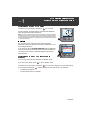
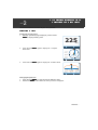
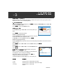
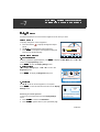
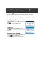
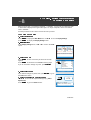
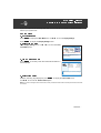
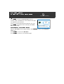
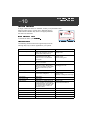
ST70 Pilot
Operating Guide
Welcome
Congratulations on having chosen a Raymarine ST70 Pilot
Controller. This gives you easy access to the important information you need to make your boating experience both safe
and enjoyable.
DODGE
TRACK
STANDBY
AUTO
+1
--1
--10
CANCEL
MENU
+10
ENTER
This Operating Guide
D10821-1
ST70 provides an adaptable, daylight-viewable color display
that you can customize to clearly show exactly what you
want.
No more, no less.
This Operating Guide tells you how to use an ST70 pilot, and describes how to switch on the
pilot, set it up and display the data you want, to best suit your style of operation.
This guide assumes that the pilot has been prepared for use in accordance with the
Commissioning Procedures in the ST70 Autopilot Controller / SmartPilot X Commissioning
Instructions.
Note: ST70 products include instruments and pilot controllers. This guide gives user instructions for the pilot controller only.
Information on using the ST70 Instrument is given in separate documentation accompanying the instrument.
Contents
Getting started
Switch on/off and introduction ...................................................................................... Card 1
Choosing the pilot view.................................................................................................. Card 2
Patterns
Choosing a navigation pattern....................................................................................... Card 3
Using special features
Using the Dodge feature................................................................................................ Card 4
Using Auto-Track ........................................................................................................... Card 5
Using Wind Vane mode ................................................................................................. Card 6
Setting your preferences
Setting the screen appearance ..................................................................................... Card 7
Choosing data units ....................................................................................................... Card 8
Clocks
Setting the correct local time ......................................................................................... Card 9
Alarms
Alarm events................................................................................................................ Card 10
Raymarine UK Ltd, Anchorage Park, Portsmouth, Hampshire PO3 5TD, United Kingdom
Tel: +44 (0) 23 9269 3611, Fax:+44 (0) 23 9269 4642
Raymarine Inc ,21 Manchester Street, Merrimack, New Hampshire 03054, USA
Tel: +1 603.881.5200, Fax: +1 603.864.4756
Part Number: 81289-1
Date: March 2008
www.raymarine.com
Important Information
WARNING: Product installation & operation
This equipment must be installed and operated in accordance with the
Raymarine instructions provided. Failure to do so could result in
personal injury, damage to your boat and/or poor product
performance.
WARNING: Navigational safety
Although we have designed this product to be accurate and reliable,
many factors can affect its performance. Therefore, it should serve
only as an aid to navigation and should never replace common sense
and navigational judgement. Always maintain a permanent watch so
you can respond to situations as they develop.
WARNING: Ensure Commissioning Procedures have been completed
If the ST70 Commissioning procedures have not been completed, your
instrument could be displaying misleading information. Before using
ST70, ensure that the Commissioning Procedures (in the ST70 Autopilot
Controller / SmartPilot X Commissioning Instructions) have been
successfully carried out.
EMC conformance
All Raymarine equipment and accessories are designed to the best industry standards for use in the
recreational marine environment.
The design and manufacture of Raymarine equipment and accessories assures compliance with the
appropriate Electromagnetic Compatibility (EMC) regulations, but correct installation is required to ensure
that performance is not compromised.
Information
The information in this guide is valid for ST70 Instruments and systems which have been installed and
commissioned in accordance with the correct Raymarine procedures. Relevant documents are:
• ST70 Instrument User Reference Manual (contains commissioning, maintenance & troubleshooting
procedures).
• ST70 Instrument Installation Manual.
• SeaTalk NG Reference Manual.
Handbook information
To the best of our knowledge, the information on in this operating guide was correct when it went to press.
However, Raymarine cannot accept liability for any inaccuracies or omissions.
In addition, our policy of continuous product improvement may change specifications without notice.
Therefore, Raymarine cannot accept liability for any differences between the product and the information
in this guide.
Waste Electrical and Electronic (WEEE) Directive
The WEEE Directive requires the recycling of waste electrical and electronic equipment.
Whilst the WEEE Directive does not apply to some of Raymarine's products, we support its policy
and ask you to be aware of how to dispose of this product.
The crossed out wheelie bin symbol, illustrated above, and found on our products signifies that this product
should not be disposed of in general waste or landfill.
Please contact your local dealer, national distributor or Raymarine Technical Services for information on
product disposal.
Copyright Raymarine 2008
Card
ST70 pilot - getting started
Switch on/off & introduction
1
Switching on your ST70 Pilot
To switch on your ST70 pilot, hold down
STANDBY
for 1 second.
N
TWS KTS
W
E
6.2
Depth M
S
14.8
M
SOG KTS
DODGE
TRACK
STANDBY
AUTO
+1
--1
--10
MENU
CANCEL
+10
ENTER
Important
Do not use the pilot until it has been commissioned as
described in the ST70 Autopilot Controller / SmartPilot X Commissioning Instructions.
If you power up and a CHOOSE LANGUAGE page is displayed,
the pilot has not been commissioned since it was installed, so
you need to carry out the commissioning procedure before
using the pilot.
Switching off an ST70 Pilot when in
Standby
D10925-1
Note: If power to a system to which ST70 pilot or instrument is connected is switched
centrally (e.g.from a central circuit breaker), the on/off condition of each individual instrument or pilot when system power is applied reverts to what it was when the system
power was last switched off. See the ST70 Autopilot Controller User Reference Guide
for system power protocol.
19.1
Language
English (UK)
Press ENTER to select
DODGE
TRACK
STANDBY
AUTO
+1
--1
--10
CANCEL
MENU
+10
ENTER
Dxxxxx-1
The pilot powers up and shows the page that was displayed
when the power was last switched off.
You can only switch off your pilot when in Standby mode.
If you are in Auto mode, press
STANDBY
to go to Standby mode.
To switch off your ST70 pilot, hold down
STANDBY
for 1 second, to display the count-down popup,
then continue to hold down
until the display counter reaches zero. At that point:
• The display goes blank.
• The pilot power down is complete.
STANDBY
continued ...
ST70 instrument - getting started
Switch on/off & introduction
Card
1
continued
Resolving problems
In the unlikely event that you experience problems using your ST70 pilot, refer to the troubleshooting procedures in the ST70 Autopilot Controller User Reference Guide.
If you need further assistance, please visit the Customer Support area of our web site at:
www.raymarine.com
As well as providing a comprehensive Frequently Asked Questions section and servicing
information, our web site gives e-mail access to the Raymarine Technical Support Department
and details of the locations of Raymarine agents, worldwide.
Telephone help line
If you do not have access to the world wide web, please call our help line.
In the USA, call:
•
+1 603 881 5200 extension 2444
In the UK, Europe the Middle East or the Far East, call:
•
•
+44 (0) 23 9271 4713 (voice)
+44 (0) 23 9266 1228 (fax)
Help us to help you
When requesting service, please quote the following product information:
• Equipment type.
• Model number.
• Serial number.
• Software version.
• Hardware version.
You can find out this information by running the About Display diagnostic function (described
in the ST70 Autopilot Controller User Reference Guide).
Card
2
ST70 Pilot - selecting the view
Selecting the Pilot View
Use these instructions to select the pilot view you want.
Selecting a view
Displaying the pilot views
1.
With any operational page displayed, press and hold
MENU to display Heading View.
225
2.
D10931-1
Mag
Press and hold MENU again to display 2D - Compass
Rose View.
N
19.1
TWS KTS
W
E
6.2
Depth M
S
14.8
M
D10935-1
SOG KTS
3.
Press and hold MENU again to display 3D - Isometric View.
N
M
19.1
Depth M
14.8
SOG KTS
D10930-1
TWS KTS
6.2
Changing the pilot view
1.
2.
Press and hold MENU to cycle through the different views.
Release the MENU button when the view you want is displayed.
continued ...
ST70 Pilot - selecting the view
Selecting the Pilot View
Card
2
continued
Card
ST70 Pilot - Patterns
3
Selecting a pattern
Selecting a pattern
Different patterns are available depending on whether the system is set up for power boat or
fishing boat. There are no sailboat patterns.
1. Go to Main Menu
With any operational page displayed, press MENU to display the Main Menu, then use < or > to
scroll to the Patterns option.
Press ENTER to show the Patterns menu.
Select option
At the Patterns page, use
want.
Main Menu
< or > to scroll to the pattern you
All Patterns
Pattern 1 (Fishing boat only)
D10929-1
Press ENTER to select the pattern.
Press ENTER to select.
Selecting Pattern 1 will select the most frequently used pattern of the most recent 10 patterns used.
Use < and > to scroll to Pattern 1 and press ENTER.
Pattern 2 (Fishing boat only)
Selecting Pattern 2 will select the second most frequently used pattern of the most recent 10
patterns used.
Press MENU, then use
< and > to scroll to Pattern 2 and press ENTER.
All Patterns
Pattern Settings
Direction
Radius
Use < and > to scroll to the required pattern, then press
ENTER to edit or CANCEL to exit.
When you select a pattern, the settings for that pattern will
be displayed. You can change the settings.
When the settings are as you require, press AUTO to
engage the pilot and start the pattern.
i
Port
0.3NM
Press ENTER to EDIT.
Press AUTO to engage.
The preset patterns and the settings you can specify are:
Pattern
Settings
Circle
Direction (port or starboard) and radius
Zigzag
Direction (port or starboard), Angle and Length
Cloverleaf
Direction (port or starboard)
Radius
continued ...
D10928-1
Press MENU, then use < and > to scroll to All Patterns and
press ENTER.
ST70 Pilot - patterns
Selecting a Pattern
Card
Pattern
Settings
Spiral
Direction (port or starboard)
Radius
Radius Increment
On Heading Radius
On Heading Increment
Circle against heading
Direction (port or starboard) and Distance
Figure of eight
Direction (port or starboard) and Radius
Pattern Search
Direction (port or starboard)
Width
Height
Increment Width
Increment Height
Box Search
Direction (port or starboard), Width, Height
180° Turn
Direction (port or starboard) and Radius
3
continued
Card
4
ST70 Pilot - using dodge
Using the Dodge feature
The Dodge feature allows you to leave your current mode and go to Standby in order to temporarily change course.
Once you have changed course you have the choice of continuing on the new course or
returning to your previous heading.
If your ST70 pilot is not connected to a compatible course computer, pressing DODGE will simply take the pilot to Standby.
Using Dodge in Auto mode
The DODGE popup will appear over whichever pilot view you
have currently selected.
Once you have finished steering manually you can:
• Press DODGE to return to the previous heading, or
• Press AUTO to continue on your new heading.
DODGE
N
follow last
DODGE
19.1 heading (300°)
W
E
follow this
6.2
AUTO
TWS KTS
Depth M
heading (272°)
S
14.8
M
SOG KTS
D10933-1
When in Auto mode, press DODGE.(requires a dodge compatible
chartplotter).
Using Dodge in Track mode
The DODGE popup will appear over whichever pilot view you
have currently selected.
DODGE
DODGE
19.1
TWS KTS
Once you have finished steering manually you can:
• Press DODGE to track from here to the next waypoint, or
• Press AUTO to return to the previous track.
Note: The Dodge when in Track mode feature on only available on compatible multifunction displays.
6.2
TRACK
Depth M
14.8
SOG KTS
N
Track from here
W
E
Resume current
Track
S
M
D10932-1
When in Track mode, press DODGE.
ST70 Pilot - using dodge
Using the Dodge feature
Card
4
continued
Card
5
ST70 Pilot – using special features
Using the Track feature
The Track mode feature enables you to instruct the pilot to steer to a series of waypoints,
comprising of a route generated by a chartplotter.
Using Track
Start with the SmartPilot in AUTO mode and your chartplotter following a route.
1. Press TRACK to enter Track mode.
2. Wait for the warning to sound.
N
TRACK
The display will show the bearing to the next planned
waypoint and the direction in which the boat will turn to reach
19.1 TURN TO
TWS KTS
W
this waypoint.
WAYPOINT
6.2
45°
E
001
Press TRACK to accept
S
M
D10919-1
SOG KTS
If it is safe for the boat to turn onto the new course, press the
TRACK button. The SmartPilot will turn the boat onto the
new course, and the display will show the heading required
to achieve the required track.
Note: The rate of turn when in Track mode is set using the TURN RATE calibration setting. Adjust this as appropriate for optimum comfort. If the boat is more than 0.3 nm from
the track, the Large Cross Track Error warning will sound.
TRACK
N
19.1 CHECK TURN
W
E
WAYPOINT
150° 001
6.2
TWS KTS
Press TRACK to accept
S
SOG KTS
As you approach each waypoint, at the preset arrival circle, an
alarm will sound and the Track popup will be displayed:
M
D10920-1
3.
Press TRACK to accept the new heading or CANCEL to return to the previous screen.
Skipping a waypoint
If you want to advance to the next waypoint before you have arrived at the target waypoint,
you can skip a waypoint by pressing TRACK for 1 second. The display will then show the
Waypoint Advance screen for the next waypoint. Check it is safe to turn, then press TRACK to
turn the boat towards the next waypoint.
Using Dodge while in Track mode
In Track mode you still have full control from the keypad. You can make a dodge maneuver by
pressing DODGE. Refer to “Using Dodge in Track mode” on page 9.
Leaving Track mode
You can leave Track mode at any time by:
• pressing AUTO to return to Auto mode.
• pressing STANDBY to steer manually in Standby mode.
ST70 Pilot – using special features
Using the Track feature
Card
5
continued
Card
6
ST70 Pilot – using special features
Using Wind Vane mode
When the SmartPilot is in Wind Vane mode it uses the wind angle as the primary heading reference. As changes in the true or apparent wind angle occur, it adjusts the locked heading to
maintain the original wind angle.
Selecting Wind Vane mode
Main Menu
Wind Vane Mode
Press ENTER to select.
D10827-1
You can select Wind Vane mode from either Standby or
Auto mode:
1. Steady the boat onto the required wind angle.
2. Press MENU, then use < and > to select Wind Vane
mode and lock the current wind angle. The display
shows the locked heading (e.g. 128°) and the wind
angle (e.g. WIND 145P indicates an wind angle of 145°
to port).
3. The SmartPilot will then adjust the boat’s heading to
maintain the locked wind angle.
Adjusting the locked wind angle
You can adjust the locked wind angle by using the 1, +1 , 10 and +10 buttons to change
course. For example, to bear away by 10° when the boat is on a starboard tack:
• press 10 to turn the boat 10° to port – the locked wind angle and locked heading will both
change by 10°.
• the autopilot will then adjust the locked heading as required to maintain the new wind
angle.
Note: Because turning the boat affects the relationship between the true and apparent wind angles, you should only use this
method to make minor adjustments to the wind angle. For major changes, return to Standby mode, steer onto the new heading,
then reselect Wind Vane mode. Refer to the ST70 Autopilot Controller User Reference Guide for the procedure for changing
the wind reference between True and Apparent.
Leaving Wind Vane mode
You can leave Wind Vane mode by:
• pressing AUTO to return to Auto mode.
• pressing STANDBY to return to manual control.
ST70 Pilot – using special features
Using Wind Vane mode
Card
6
continued
Card
ST70 pilot – setting your preferences
Setting the screen appearance
7
You can change the brightness of the screen, and the color scheme to use.
Brightness
Use these instructions to set the screen brightness to the level you want.
Quick Set Up
To quickly change the screen brightness:
N
a. Press and release
to display the brightness adjust
popup.
b. Use < or > to set the required screen brightness.
c. Press ENTER to accept the new brightness setting and
return to your operational page.
STANDBY
19.1
Brightness
TWS KTS
55%
6.2
Depth M Press ENTER to accept
S
14.8
Alternative method
M
D10936-1
SOG KTS
1. Go to Main Menu
With any operational page displayed, press MENU to display the Main Menu, then use < or > to
scroll to the Display Settings option.
Press ENTER to show the Display Settings menu.
2. Select option
At the Display Settings page, use < or
Brightness option.
> to scroll to the
Display Settings
Press ENTER to display the Brightness setup box.
Brightness
3. Set level
Use < or > to set the screen brightness, as required.
Press ENTER to save the selection and return to the Display
Settings menu.
Adjust the display brightness.
Press ENTER to select.
D10814-1
i
Brightness
100
%
To return to normal operation from the Display Settings
menu:
a. Press CANCEL to return to the Main Menu.
b. Press CANCEL again to return to your operational page.
< & > adjust brightness. CANCEL
i exits without saving.
Press ENTER to accept.
D10815-1
Returning to normal operation
continued ...
ST70 pilot – setting your preferences
Setting the screen appearance
Card
7
continued
Choosing colors
Use these instructions to set the screen colors for optimum viewing. You can choose from
three daytime and three night-time settings. If you have other compatible pilots or instruments
installed, these settings will be applied to them at the same.
1. Go to Main Menu
With any operational page displayed, press MENU, to display the Main Menu, then use
to scroll to the Display Settings option.
< or >
Press ENTER to show the Display Settings menu.
2. Go to Colors select box
At the Display Settings menu, use < or > to scroll to the Colours option.
Display Settings
Press ENTER to display the Colours select box.
Colours
3. Select option
At the Colours select box, use < or > to select the color
scheme that best suits your current viewing conditions.
Press ENTER to save the selection and return to the Display
Settings menu.
Select the display colour palette.
Press ENTER to select.
D10816-1
i
Colors
Day1
< & > adjust colour.
To return to normal operation from the Display Settings menu:
a. Press CANCEL to select the Main Menu.
b. Press CANCEL again to return to your operational page.
Press ENTER to accept
D9335-1
Returning to normal operation
i CANCEL exits without saving.
Card
8
ST70 Pilot – setting your preferences
Choosing data units
When an ST70 pilot is connected to SeaTalkng or SeaTalk2, you can use it to select the units
in which data is displayed throughout the system. A range of imperial, metric and nautical
units is available.
Use the procedure on this card to choose the units you want.
Choosing data units
1. Select Main Menu
Press MENU to display the Main Menu then use < or > to scroll to Display Settings.
Press ENTER to display the Display Settings menu.
2. Initial actions
At the Display Settings menu, use < or > to scroll to the Units
option.
Display Settings
Units
Change the default unit settings.
3. Units summary
Press ENTER to select.
Units
Speed
Distance
Depth
Wind Speed
Heading
Flow Rate
Temperature
If you do not want to change any units, press CANCEL.
i
4. Units select menu
If you want to change any of the units, press ENTER, to go to
the Units select menu.
5. Select the units you want to change
Use < or > to scroll to the required data type (e.g. Wind
Speed Units)
Press ENTER to go to the Units edit box.
KTS
NM
FT
KTS
M
G/H
o
C
These are your current settings.
Press ENTER to continue
D9439-1
Press ENTER to select the second Units summary page.
Wind Speed Units
KTS
Use < & > to adjust.
i CANCEL exits without saving.
Press ENTER to accept
D9442-1
Press ENTER to show a summary of the Units currently
applied.
D10839-1
i
continued ...
ST70 instrument – setting your preferences
Choosing data units
Card
8
6. Set the units
Use < or > to scroll to the required units.
Press ENTER to save your setting and return to the Units summary page.
Press ENTER to select the second Units summary page.
Press ENTER to go to the Units select menu.
If you want to set other units, repeat steps 5 and 6.
Returning to normal operation
When you have finished setting the units and the Units select menu is displayed:
a. If necessary, use < or > to scroll to the Continue option.
b. Press ENTER to return to your operational page.
continued
Card
9
ST70 Pilot – clocks
Setting the correct local time
If your ST70 pilot is not receiving GPS data, you can use this procedure to specify the local
time as your system time.
Set the time
1. Go to Main Menu
Press MENU to display the Main Menu then use < or > to scroll to Display Settings.
Press ENTER to display the Display Settings menu.
2. Select Time & Date
At the Display Settings menu, use < or > to scroll to the Time
and & Date option.
Display Settings
Time & Date
3. Time & Date summary
Time & Date
i
4. Select time offset
13:30
16/11/07
0.0
24-hour
dd/mm/yy
Time
Date
Time Offset
Time Format
Date Format
These are your current settings.
Press ENTER to continue
D10923-1
Press ENTER. A summary of the time and date information is
then displayed.
Press ENTER to select.
D10838-1
Change the default time and
i date settings.
With the summary page displayed, press ENTER to display the Time & Date menu.
Use < or > to scroll to the Set time offset option.
Note: If you want to change the time or date format, use the procedure described in the ST70 Autopilot Controller User Reference Guide.
continued ...
ST70 Pilot – clocks
Setting the correct local time
Card
9
continued
5. Set time offset
The time offset is the difference in time between GMT (time
at Longitude 0°) and local time.
Set time offset
-1.0
hrs
Use < or > to set the appropriate time offset for your area.
Press ENTER to accept the value and display the Time &
Date summary page.
Returning to operational page
Use < & > to adjust.
i CANCEL exits without saving.
Press ENTER to accept
With the Time & Date summary page displayed, press CANCEL to return to the Display Settings menu.
Press CANCEL to return to the Main Menu.
Press CANCEL to return to your operational page.
D9549-1
Press ENTER to display the Set time offset setup box.
Card
ST70 Pilot – alarms
Alarm events
10
Alarm indications
A range of alarm functions are available, to alert you to particular events.
When an alarm occurs, a popup box is displayed and an
audible alarm indication may sound. The popup identifies
the reason for the alarm.
AUTO
N
OFFCOURSE
If an alarm occurs
W
Steer to STARBOARD
E
6.2
To silence the alarm, press CANCEL.
Press CANCEL to silence alarm
M
Alarm events
D10938-1
S
SOG KTS
The following alarm functions are supported by the ST70,
although they may not all be applicable to your system.
Alarm
Description
Action
Calibration required
The pilot has not been fully calibrated. This will appear for a few
seconds after initial power-up.
Self-cancelling.
Change mode.
Off course
Vessel is off course by more than
the predetermined limit. May
appear in Auto, Track and Wind
Trim modes.
Change mode.
Change course.
Reduce heading error.
Route complete
Indicates completion of a route,
when in Track mode.
Change mode.
Large Cross Track Error
The cross track error (XTE) is
Change mode.
greater than 0.3nm. May appear
Data flagged as valid.
when in Track mode or when entering Track mode from any other
mode.
Loss of waypoint data
Wind shift
Apparent wind angle has changed
by more than 15 degrees.
Change mode.
Change course.
Reduction in change of wind angle.
Auto release
Safety alarm.
Auto release (SD)
Safety alarm.
Drive stopped
Safety alarm. A rudder stall condi- Change mode.
tion has persisted for more than a Reversal of drive demand.
predetermined time, and power has
been removed from the drive unit.
May appear in Auto, Track and
Wind Trim modes.
Seatalk 1 fail
Safety alarm.
Seatalk 2 fail
Safety alarm.
EEPROM corruption
Safety alarm.
No pilot
Safety alarm.
No compass
Safety alarm.
continued ...
Alarm
Description
Rate gyro fault
Safety alarm.
Current limit
Safety alarm.
Rudder feedback unit fault
Safety alarm.
Autolearn fail 1 (not carried
out)
Safety alarm.
Action
Autolearn fail 2 (manual inter- Safety alarm.
vention)
Autolearn fail 3 (compass or
drive error)
Safety alarm.
Autolearn fail 4
Safety alarm.
Autolearn fail 5
Safety alarm.
Autolearn fail 6
Safety alarm.
Turn rate too high
Safety alarm. Indicates an excessive turn rate when calibrating the
fluxgate compass. May appear in
Calibration mode.
Change calibration stage.
Reduce turn rate.
Low battery
No navigation data
Absence of one of the following:
Compass (Auto, Track and Wind
Trim modes).
XTE (Track mode).
Wind angle (Wind Trim mode)
MOB
Pilot start up
Waypoint advance
Waypoint advance Turn to
port
Waypoint advance Turn to
starboard
No wind data
No speed data
Drive short
Clutch short
Solenoid short
Indicates change of waypoint when Change mode.
in Track mode.
Accept new waypoint/leg.