1
Application ModuleX
User Guide
AX09-200
Application ModuleX
Application ModuleX
User Guide
AX09-200
Release 200
5/96
Copyright, Notices, and Trademarks
© Copyright 1994 by Honeywell Inc.
Revision 03 – May 1, 1996
While this information is presented in good faith and believed to be accurate,
Honeywell disclaims the implied warranties of merchantability and fitness for a
particular purpose and makes no express warranties except as may be stated in its
written agreement with and for its customer.
In no event is Honeywell liable to anyone for any indirect, special or consequential
damages. The information and specifications in this document are subject to
change without notice.
TotalPlant and TDC 3000 are U.S. registered trademarks of Honeywell Inc.
OpenUSE is a trademark of Honeywell Inc.
Other brand or product names are trademarks of their respective owners
Honeywell
Industrial Automation and Control
Automation College
2820 West Kelton Lane
Phoenix, AZ 85023
(602) 313-5669
ii
Application ModuleX User Guide
5/96
About This Publication
This publication is intended for Application ModuleX users—application developers and
administrators. It includes an overview of the Application ModuleX and describes its function in the
Honeywell TotalPlant environment. It addresses the security features of the Application ModuleX,
and includes an introduction and example of the use of OpenDDA functionality to access LCN data
from an application.
This publication is not intended to serve as a reference manual. The application developer should
refer to the OpenDDA publications for detailed reference material. The system administrator should
refer to the Application ModuleX System Administration manual for specific system administration
procedures, and the maintenance person should refer to Application ModuleX Service and
Application ModuleX Troubleshooting for reference information.
This publication supports AXM release R200 and TDC 3000X software releases R430 and later
R4xx versions, and R500 and later R5xx versions.
5/96
Application ModuleX User Guide
iii
iv
Application ModuleX User Guide
5/96
Table of Contents
SECTION 1 – OVERVIEW .......................................................................................... 1
1.1
Introduction.......................................................................................... 1
1.2
Application ModuleX Architecture .......................................................... 4
1.3
Application ModuleX System Configurations........................................... 7
SECTION 2 – SECURITY.......................................................................................... 13
2.1
HP-UX Security ................................................................................... 13
2.2
Physical and Procedural Security ......................................................... 15
2.3
LCN Security ...................................................................................... 16
SECTION 3 – FILE SYSTEM ..................................................................................... 21
3.1
Overview............................................................................................ 21
3.2
Directories .......................................................................................... 22
3.3
Files ................................................................................................... 23
SECTION 4 – PERFORMANCE MEASUREMENT...................................................... 27
4.1
Overview............................................................................................ 27
4.2
$RCVSTA(n) Parameter ...................................................................... 30
4.3
$RCVCNT(n) Parameter ...................................................................... 32
4.4
$XMITSTA(n) Parameter...................................................................... 34
4.5
$XMITCNT(n) Parameter...................................................................... 35
SECTION 5 – HIBERNATION .................................................................................... 37
5.1
Overview............................................................................................ 37
5.2
CL Support......................................................................................... 39
5.3
OpenDDA Support ............................................................................. 43
5.4
X-Side Support Tools.......................................................................... 44
SECTION 6 – CONFIGURATION OF DATA ACCESS PRIORITY .................................. 47
6.1
Introduction........................................................................................ 47
6.2
The xdaconfig..................................................................................... 50
5/96
Application ModuleX User Guide
v
Figures and Tables
vi
Figure 1-1
Figure 1-2
Figure 1-3
Figure 1-4
Figure 1-5
Figure 3-1
Figure 5-1
AXM Block Diagram ............................................................................ 1
Standalone Coprocessor Configuration............................................... 7
Minimum Network Configuration with a UXS ......................................... 8
Minimum Network Configuration with an MP-AXMST1........................... 9
Initial Setup and Maintenance Configuration ...................................... 11
Base File System Structure............................................................... 21
Relationship of CL Events and X-side Hibernation.............................. 38
Table 1-1
Table 1-2
Table 1-3
Table 3-1
Table 3-2
Table 3-3
Table 3-4
Table 3-5
Table 3-6
Table 3-7
Table 4-1
Table 4-2
Table 4-3
Table 4-4
Table 4-4
Table 4-5
Table 4-6
Table 5-1
AXM Five-Slot Module Configuration ................................................... 4
AXM Ten-Slot Module Configuration ................................................... 4
Function of AXM Components............................................................ 5
Key Directories ................................................................................ 22
Reference Configuration Files .......................................................... 23
Working Configuration Files.............................................................. 24
Data Files......................................................................................... 24
Executable Files .............................................................................. 25
Library Files ..................................................................................... 26
Modified HP-UX Files........................................................................ 26
Using the AXMPERF Schematic........................................................ 28
Using the DATACHNG Schematic ..................................................... 28
Elements of the $RCVSTA(n) Array................................................... 30
Elements of the $RCVCNT(n) Array................................................... 32
Elements of the $RCVCNT(n) Array................................................... 33
Elements of the $XMITSTA(n) Array .................................................. 34
Elements of the $XMITCNT(n) Array .................................................. 35
Event Data Structure........................................................................ 43
Application ModuleX User Guide
5/96
Acronyms
AXM...................................... Application ModuleX (Application Module with Extensions)
DAT ................................................................................................. Digital Audio Tape
LAN ................................................................................................Local Area Network
LCN ............................................................................................Local Control Network
OpenDDA ................................................................ (Open) Data Definition and Access
PCDE.............................................................................................. PC Data Exchange
PIN........................................................................................ Plant Information Network
SAM............................................................................. System Administration Manager
TCP/IP ..................................................Transmission Control Protocol/Internet Protocol
TDC ........................................................................................ Total Distributed Control
TPH ..................................................................................................Total Plant History
UCN...................................................................................... Universal Control Network
US ..................................................................................................... Universal Station
UXS ............................................. Universal StationX (Universal Station with Extensions)
WSI.............................................................................................. Workstation Interface
5/96
Application ModuleX User Guide
vii
References
Publication
Title
Publication
Number
Application ModuleX System
Administration
Binder
Title
Binder Number
AX11-200
Application ModuleX
TDC 2094/3094
Application ModuleX Service Manual
AX13-410/510
Application ModuleX
TDC 2094/3094
Application ModuleX Troubleshooting
AX13-200
Application ModuleX
TDC 2094/3094
viii
Application ModuleX User Guide
5/96
Section 1 – Overview
1.1
Introduction
What is the
Application ModuleX?
The Application ModuleX (AXM) is a major component of Honeywell’s
TotalPlant Open Solutions. It uses a dual-processor architecture—a
traditional Application Module (AM) combined with a powerful workstation
processor, which we will refer to as the coprocessor. The Application
Module provides reliability, security, and a link to the TDC 3000X process
control subsystem that may already exist at the customer’s plant, preserving
investment in process control hardware and software. The coprocessor
uses industry-standard, state-of-the-art workstation hardware and software,
providing an open environment for development and execution of advanced
process control programs and for acquisition of data for higher-level
production control functions. The coprocessor provides a link to the Plant
Information Network—an Ethernet LAN that can include PCs,
workstations, and mainframes, all contributing to the overall operation of
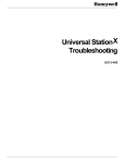
the plant. Figure 1-1 shows a block diagram of the AXM.
Figure 1-1
AXM Block Diagram
Plant Information
Network (PIN)
Co-Processor
(UNIX)
Software
HP-UX
X Application
LCN Server
Hard
Drive(s)
Communication
Interface
LCN
Node
Processor
AM
Local Control
Network (LCN)
- AM (CL)
- Points
- Custom Data
Segments
40000
Continued on next page
5/96
Application ModuleX User Guide
1
1.1
Introduction,
The control and
information domains
Continued
The collection of hardware and software that is most intimately involved in
the control of the process is referred to as the control domain. This includes
the traditional LCN and its nodes and control programs, the UCN and Data
Hiway and their controllers, and the field instrumentation infrastructure—
the sensors, valves, and other control elements.
The information domain includes the various processors connected to the
Plant Information Network (PIN)—PC, Macintosh, VAX, and mainframe
platforms, as well as UXS and AXM coprocessors. These computers use
data generated by the control domain for production management functions
such as unit cost and quality measurement, inventory control and inventory
cycle time analysis, scheduling, process optimization, and other production
management functions.
OpenUSE
The software “glue” that connects the control and information domains is
the Honeywell OpenUSE environment. It includes CL/AM enhancements,
security features, coprocessor development resources, and the standard
OpenDDA (Data Definition and Access)—the support software that allows
a coprocessor application program to access LCN data.
Open yet secure
In order to provide an environment that is both open and secure, Honeywell
has carefully chosen the areas to open. By embracing the Fieldbus
standard, Honeywell has opened up the instrumentation level so as to be
compatible with industry standard devices from a large number of vendors.
By adding a standard workstation with PIN interface as a coprocessor in the
US and AM (thereby creating the UXS and AXM), Honeywell has
provided users and third-party developers with a means to develop
powerful applications using standard languages, that run on standard
platforms, and that can use live process data.
While the field instrumentation level and the information domain level are
now open, the LCN and its process controllers are retained so as to
continue the security and reliability that are the hallmark of the TDC 3000X.
The “view of the process” and the “path to the valve” are not compromised
in the OpenUSE environment.
Continued on next page
2
Application ModuleX User Guide
5/96
1.1
X Windows
environment
Introduction,
Continued
Computers on the PIN can use the X Windows Client/Server environment.
This requires:
• A 5-10 Mbit Ethernet or Token Ring Local Area Network (the PIN)
• TCP/IP and X11.R5 (or later) software in both clients and servers
• Motif window manager software in all clients
The power and versatility of the X Windows environment allows a user on
a PIN device of a given platform (for example, a PC configured as an XServer ) to open a window and run an application in another PIN device that
is of a different platform (for example, an AXM whose coprocessor is
running HP-UX).
In X Windows convention, the client is the device running the application
and the device providing the screen, keyboard, and mouse services is the
server.
5/96
Application ModuleX User Guide
3
1.2
Application ModuleX Architecture
Chassis types
The AXM is available in three chassis configurations:
• Five-Slot Module—uses the K4LCN node processor, which has
hardware floating point support (R500)
• Five-Slot Module—uses the K2LCN node processor, and therefore does
not support hardware floating point
• Ten-Slot Module—uses the HMPU, which has hardware floating point
support
Five-Slot Module
configuration
The following table shows the configuration of the Five-Slot Module
versions of the AXM.
Table 1-1
AXM Five-Slot Module Configuration
Slot
Ten-Slot Module
configuration
Front
Rear
5
Optional Application Board
Optional I/O board
4
Hard Disk Drive Tray
3
(occupies two slots)
HDDT I/O
2
WSI2
WSI2 I/O
1
K2LCN/K4LCN
LCN I/O
The following table shows the configuration of the Ten-Slot Module
version of the AXM.
Table 1-2
AXM Ten-Slot Module Configuration
Slot
Front
Rear
10
Unusable slot
9
Unusable slot
8
Hard Disk Drive Tray
7
(occupies two slots)
HDDT I/O
6
WSI2
WSI2 I/O
5
Optional Application Board
Optional I/O board
4
Optional memory board
3
QMEM-4
2
LLCN
1
HMPU
LCN I/O
Continued on next page
4
Application ModuleX User Guide
5/96
1.2
Function of
components
Application ModuleX Architecture,
Continued
The following table lists the function and options for each of the
components listed in Tables 1-1 and 1-2.
Table 1-3
Function of AXM Components
Component
K4LCN
Function
Node processor used in Five-Slot Module AXM (R500).
Available with the following memory sizes:
• 4 Mw (Note: AXM R200 requires a minimum of 6 Mw)
• 8 Mw
• 16 Mw
Has hardware floating point support.
K2LCN
Node processor used in Five-Slot Module AXM. Available with
the following memory sizes:
• 4 Mw (Note: AXM R200 requires a minimum of 6 Mw)
• 8 Mw
Does not have hardware floating point support.
HMPU
Node processor used in Ten-Slot Module AXM. Has 2 Mw of
memory. Has hardware floating point support.
LLCN
LCN interface board (used only with HMPU version—this
function is built into the K2LCN and K4LCN)
LCN I/O
I/O paddleboard that provides connection to the LCN A and
LCN B cables.
QMEM-4
Memory board—provides 4 Mw additional memory. Used only
with HMPU version
WSI2
Workstation Interface board. Contains the coprocessor board.
Available with the following coprocessor memory options:
• 32 MB
• 64 MB
• 128 MB
• 256 MB
Available with the following coprocessor speed options:
• 64 MHz
• 100 MHz
WSI2 I/O
I/O paddleboard associated with the WSI2 board. Provides
interface to the PIN and to a console terminal or modem.
Continued on next page
5/96
Application ModuleX User Guide
5
1.2
Application ModuleX Architecture,
Function of
components
(continued)
Table Table 1-3
Continued
Function of AXM Components (continued)
Component
Hard Disk
Drive Tray
Function
Holds a primary hard disk drive and an optional hard disk drive.
Each drive can be either:
• 525 MB
• 1 GB
• 2 GB
This tray occupies two card slot positions.
HDDT I/O
I/O paddleboard associated with the hard disk drive tray.
Contains an optional SCSI interface connector that is not used
with AXM and that must have a cable terminator installed.
Coprocessor hardware
The coprocessor, a Hewlett-Packard Model 743 processor board, is
mounted on the WSI2 board. (This board is also used in the Release 200
Universal StationX.) The board is based on the Hewlett-Packard PA-RISC
chip (Precision Architecture-Reduced Instruction Set Computing). The
coprocessor is available in 64 MHz and 100 MHz versions, and with 32
MB, 64 MB, 128 MB, or 256 MB of memory.
Coprocessor software
The coprocessor operating system is version 9.05 of HP-UX. HP-UX is
based on UNIX System V. It includes many of the most popular
extensions from the University of California, Berkley, version of UNIX,
and provides full or partial compliance to numerous industry and
international standards. For more information about the HP-UX operating
system, refer to the Hewlett-Packard CD-ROM documentation.
6
Application ModuleX User Guide
5/96
1.3
Application ModuleX System Configurations
Introduction
The Application ModuleX can be used in a variety of ways. We will cover
a few configurations that we anticipate will be typical usage scenarios, but
they are not intended to represent all possible configurations.
Standalone
coprocessor
The standalone coprocessor configuration shown in Figure 1-2 is the
simplest configuration. Its characteristics are:
• Shipped with one or more applications preloaded and ready to run
• There is no Ethernet LAN (PIN) connection; therefore, there is no access
to external media, which impacts as follows:
– Data generated by an application cannot be used by other devices
– You cannot backup the hard disk
– You cannot load optional software or load software upgrades
• If the hard disk fails, it must be replaced with a new drive that has the
operating system and applications preloaded by the application supplier
unless you have the optional DAT drive and have the necessary tapes
• From a network security standpoint, this is the most secure configuration
because there is no PIN connection
• From a US or UXS on the LCN, you can activate CL that uses the
AMCL06 extension set to initiate AXM applications
Note: If the AXM is equipped with the optional DAT drive and a console
device, you can backup the disk and load software.
Figure 1-2
Standalone Coprocessor Configuration
No PIN
Connection
CD-Rom
DAT
A XM
Coprocessor
AM
LCN
51315
Continued on next page
5/96
Application ModuleX User Guide
7
1.3
Application ModuleX System Configurations,
Minimum network
configuration with UXS
Continued
If applications will be developed locally, or if access to a removable media
drive is required for backups, software installation, or other system
administration tasks, then a minimum of one other network-resident device
is required. This can be a UXS, as shown in Figure 1-3. The
characteristics are:
• The AXM and UXS are the only terminals on a point-to-point local LAN
• The absence of other devices on the LAN makes this configuration
secure from the standpoint of network security
• System administration tasks can be performed from the UXS by doing a
remote login (rlogin) to the AXM over the network and using SAM—a
system administration manager utility supplied with HP-UX
• The Digital Audio Tape (DAT) drive on the UXS can be used for hard
drive backups and for software installations and upgrades
• You can develop AXM applications from a window at the UXS while
logged into the AXM
• The UXS can be used as the console terminal of the AXM for initial
network configuration and for maintenance—this is accomplished by
connecting the UXS serial printer port to the AXM console port with a
null modem cable, and by using terminal emulation software in the UXS
(Kermit software is supplied with the UXS)
• From the UXS (or from any US or UXS on the LCN), you can activate
CL that uses the AMCL06 extension set to initiate AXM applications
Figure 1-3
Minimum Network Configuration with a UXS
Point-to-Point Ethernet LAN
CD-Rom
DAT
Coprocessor
A XM
AM
Coprocessor
DAT
UXS
LCN
US
LCN
51316
Continued on next page
8
Application ModuleX User Guide
5/96
1.3
Application ModuleX System Configurations,
Minimum network
configuration with MP–
AMXST1 workstation
Continued
This configuration is similar to the previous configuration except that the
UXS is replaced by the Honeywell Model MP-AMXST1 System
Administration and Development Station. This device is a workstation that
includes a DAT drive and CD-ROM drive. It is an option available from
Honeywell for application development and/or system administration. The
characteristics, which are similar to the previous configuration, are:
• The AXM and workstation are the only terminals on a point-to-point
local Ethernet LAN
• The absence of other devices on the LAN makes this configuration
secure from the standpoint of network security
• System administration tasks can be performed from the workstation by
doing a remote login (rlogin) to the AXM over the network and using
SAM—a system administration manager utility supplied with HP-UX
• The Digital Audio Tape (DAT) drive on the workstation can be used for
hard drive backups and for software installations and upgrades
• You can develop AXM applications from a window at the workstation
while logged into the AXM
• Using its serial port and terminal emulation, the workstation can be used
as the console terminal of the AXM for initial network configuration and
for maintenance as described for the previous configuration
• From a US or UXS on the LCN, you can activate CL that uses the
AMCL06 extension set to initiate AXM applications
• The MP-AXMST1 provides access to the HP CD-ROM documentation
Figure 1-4
Minimum Network Configuration with an MP-AXMST1
Point-to-Point Ethernet LAN
CD-Rom
DAT
A XM
Coprocessor
AM
LCN
MP-AXMST1 DAT
Workstation
CD-Rom
51317
Continued on next page
5/96
Application ModuleX User Guide
9
1.3
Application ModuleX System Configurations,
Expanded network
configuration
Continued
The preceding configurations are characterized by minimum Ethernet LAN
networks. In the standalone configuration, the AXM is not connected to a
LAN. In the minimum configurations with MP-AMXST1 workstation or
UXS, a single point-to-point LAN is used between the AXM and the
development/administration station. These are the simplest configurations,
and the most secure with respect to network access.
At the other extreme, the AXM can be connected to a complex Ethernet
LAN that functions as the Plant Information Network. In this environment,
the AXM can coexist on the PIN with multiple devices and platforms, such
as UXS, workstation, VAX, PC, Macintosh, and mainframe. With
appropriate software and configuration, these diverse devices can utilize and
exchange LCN data and use this data in plant and process management
applications.
Continued on next page
10
Application ModuleX User Guide
5/96
1.3
Application ModuleX System Configurations,
Initial setup and
maintenance
configuration
Continued
The AXM is shipped with networking enabled, but configured for
maximum security. Permissions for all services (in /usr/adm/inetd.sec) are
set to “deny.” Root is the only user allowed to log in, and this is allowed
only from the local console terminal. If the AXM is to be connected to the
Ethernet LAN, you must connect a local console terminal and then log in as
root and perform the necessary configuration changes. After the initial
configuration, authorized users can log in from the network and perform
system administration and development activities.
The console terminal connection may also be required for system
maintenance. If the network is down, the console is the only device from
which you can access HP-UX. The console is also the only device from
which you can observe the HP-UX boot process.
The console device can be a VT100 or a device doing VT100 emulation.
Honeywell recommends and supports the use of a UXS or the optional
Model MP-AMXST1 System Administration and Development Station.
Either of these devices can be connected to the AXM console port with a
serial null modem communications cable. Both are shipped with Kermit
software, which can provide the VT100 emulation.
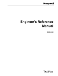
Figure 1-5
Initial Setup and Maintenance Configuration
Ethernet LAN
Null Modem Cable
9600 Baud Serial
Console
Device
CD-Rom
DAT
U XS or
VT100 or
Workstation
Coprocessor
AM
LCN
Where to find more
information
5/96
A XM
51318
The Application ModuleX Service manual contains instructions on
connecting the VT100-like terminal, UXS, or Model MP-AMXST1 System
Administration and Development Station to the console port of the AXM.
The Application ModuleX System Administration manual contains the
procedures to invoke Kermit and perform the required AXM configuration.
Application ModuleX User Guide
11
12
Application ModuleX User Guide
5/96
Section 2 – Security
2.1
HP-UX Security
Introduction
UNIX has long been touted for its security features. HP-UX is a UNIX
derivative and retains these security features. Part of this security derives
from the operating system architecture, which is designed to prevent any
program from corrupting any other program or the operating system itself.
Some important
categories
Some of the most important security categories of HP-UX are:
• File permissions
• Network security
• User security
• Audit files
These and other categories are covered in HP-UX System Security, which
is available in the HP CD-ROM documentation.
File permissions
Each file and directory can be set to allow or deny read, write, and execute
permission for each of the following:
• Owner
• Group
• Others
These permissions can be changed with the chmod (change file mode)
command. The owner and group can be changed with the chown and chgrp
commands, respectively.
Another command, chacl (change access control list), extends the
capabilities of the chmod command by allowing the user to allow or deny
file access to additional users and/or groups. Up to 13 additional sets of
permissions (called optional access control list entries) can be stored in the
access control list of the file.
Refer to the man pages and/or the HP CD-ROM documentation for detailed
information on the chmod, chown, chgrp, and chacl commands.
Continued on next page
5/96
Application ModuleX User Guide
13
2.1
HP-UX Security,
Continued
Network security
The file /usr/adm/inetd.sec allows you to allow or deny specific services to
individual users or groups of users. Examples of services are login, rlogin,
telnet, and ftp. Workstations are normally shipped with all of these
permissions set to “allow”—minimum security. The AXM, on the other
hand, is shipped with all permissions set to “deny” for maximum security.
You, the user, can relax this security and allow whatever level of access is
commensurate with the environment and mission of your AXM.
User security
HP-UX includes the traditional UNIX security features that are part of the
user management process. Each user has a login name, user ID, group ID,
and a password that is stored only in encrypted form. Passwords are not
stored anywhere in the system in plain text (unencrypted form). They are
encrypted using a highly secure technique. When a user logs in and enters
his password, it is encrypted and compared with the encrypted version
stored in the system. In high-security situations, it is important to
physically secure data transmission media between the user’s terminal and
the AXM to prevent interception of login sequences, which include the
password in plain test. It is also important to educate users on the types of
passwords to use (and the types to not use). It is also important to establish
procedures that require the users to change passwords periodically. Each
password can be set up with an aging factor—the number of days that it
remains valid. Before the period ends, the user must change to a new
password.
Audit Files
HP-UX provides the capability to audit computer use, both on an individual
and system-wide basis. You can configure the HP-UX system to audit
users, events, and system calls. You can use the System Administration
Utility (SAM) to set up the auditing functions. Refer to the HewlettPackard CD-ROM manual HP-UX System Security for additional
information about audit files.
14
Application ModuleX User Guide
5/96
2.2
Physical and Procedural Security
Physical security
Physical security involves protecting the system from damage or corruption
by human and environmental factors. Some examples of physical security
measures are:
• Fences, intrusion alarms, security guards
• Key locks, card access systems
• Fire alarms, sprinkler systems, automatic fire suppression systems.
• Secure off-site storage for backups, checkpoints, etc.
• Uninterruptible power supplies
Procedural security
You should define your security objectives and requirements and develop a
management-approved security policy. The policy should determine a set
of practices and procedures that are distributed and followed meticulously.
Some examples of security practices and procedures are:
• A procedure and schedule for backups and checkpoints
• Regulation and monitoring of login access and access to critical files and
directories
• A policy and schedule for changing passwords
• A policy requiring users to log off or use lock command when not at the
terminal
• A policy and procedure regarding audit use, review, and analysis
5/96
Application ModuleX User Guide
15
2.3
LCN Security
Overview
The TDC 3000X has a well-deserved reputation for reliability. Security
features are incorporated in the architecture and design of the AXM
hardware and software in order to preserve this reliability. These features
are designed to protect the LCN control environment from:
• X-side failures
• Intrusion by hackers or unauthorized users on the network
• Corruption while testing new software that is not fully debugged
• Human error
Topics to be covered
The security features of the AXM environment that will be covered are:
• AXM failover to AM
• Special directory for CL-initiated applications
• OpenDDA development using test data
• The global X-access switch
• The AMCL06$Store_XAccess call
• The XACCES external load module
AXM failover to AM
If an X-side failure occurs, the AM will continue to function as follows:
• The node status will go to WARNING.
• Page 2 of the Status Detail Display will display the message
WS Interface (OK -> WARNING):Work Station Interface In Process - Please wait
• CL applications that do not communicate with the X-side will continue to
function normally. These will be applications that do not use the calls in
the CL extension set AMCL06.
• CL applications that do communicate with the X-side using calls from the
AMCL06 set will get return statuses indicating errors. The specific
actions that take place when this occurs are handled in the CL
application, and therefore depend on how the application was coded.
Continued on next page
16
Application ModuleX User Guide
5/96
2.3
LCN Security,
Directory for CL-initiated
applications
Continued
Each CL-initiated application must have its executable file, or a symbolic
link to its executable file, in the directory /users/axm. It cannot be started
from CL if it is in any other directory. This directory is owned by the user
“axm” and the group associated with this directory is the group “axm.” The
permissions for this directory, as shipped, are:
Owner
Group
Other
rwx
rwx
--Application developers, when they are added to the system as users, will
normally be assigned to the group “axm.” Therefore, when a developer has
compiled and linked an application program, the permissions will allow him
to store the executable, or create a symbolic link to the executable, in
/users/axm. OpenDDA has an “Install” command option that will
automatically create the symbolic link.
If you wish to tighten security even further, you can modify the
permissions on /users/axm accordingly. For example, you can make
superuser the only user with write permission.
Using test data with
OpenDDA
OpenDDA (Data Definition and Access) provides the software tools that
allow an application to access LCN data (to read data, and with security set
properly, to write data.) An application that uses OpenDDA can be
compiled with test data imbedded in the program. The application can be
debugged off-line using this test data instead of on-line with live LCN data.
(The application can actually be developed and tested in a UXS or a
workstation; however, only the AXM can access live data.)
Continued on next page
5/96
Application ModuleX User Guide
17
2.3
LCN Security,
Continued
The global X-access
switch
The global X-access switch controls when an X-side application can write
LCN data. It is implemented by a Processor Status Data Point (PSDP)
parameter called $XACCESS which has three possible states:
• READONLY—The X-side can read but cannot write LCN data (default)
• RW_LCN_I—The X-side can read LCN data, but can write LCN data
only from applications that are initiated by CL on the LCN-side
• READWRIT—The X-side can read and write LCN data from CLinitiated and non-CL-initiated applications (this state cannot be set by any
means unless the external load module XACCES is loaded)
The state of the global X-access switch can be changed:
• From the keyboard with Engineer access
• From an LCN-side CL program (using a call available in AMCL06—the
global X-access switch cannot be changed by a normal CL write to a
parameter).
• An X-side application cannot change the global X-access switch;
however, a configuration file xaccess.cfg on the X-side provides the
restart value for the switch. The xaccess.cfg file is modifiable by the tool
xaccess, if the user has execute permission on the tool and read/write
permission on the configuration file (root only in both cases as shipped).
The configuration file xaccess.cfg is in the directory
/opt/TDC_Open/common/newconfig and the tool xaccess is in the
directory opt/TDC_Open/common/bin.
In all cases, the READWRIT state cannot be set unless the XACCES
external load module is loaded in the AM-side.
Sample session with
xaccess
The following is a sample session running the tool xaccess.
cd /opt/TDC_Open/common/bin
xaccess
XACCESS: Configuration::Read/writes by all applications allowed
0.
Read only
1.
Read/writes by LCN initiated applications allowed
2.
Read/writes by all applications allowed
Enter the new value for X to LCN access (0, 1, or 2): 2
Continued on next page
18
Application ModuleX User Guide
5/96
2.3
LCN Security
ATTENTION
Function of XACCES
5/96
Continued
ATTENTION—$XACCESS is not a checkpointed parameter. When the
AXM node personality is loaded, the restart state of $XACCESS is
determined solely by a value encrypted in the X-side file xaccess.cfg. (The
X-side must be running for the AXM node personality to load.) If the Xside is restarted while the node personality is running, state of $XACCESS
is not affected—it will remain in its current state.
The XACCES external load module, by its presence or absence, allows or
disallows writes of LCN data from non-CL-initiated X-side applications.
This is accomplished as follows:
• If XACCES is loaded, the READWRIT state of the global X-access
switch can be set by an Engineer from the keyboard, or by a CL call.
When the READWRIT state is set, non-CL-initiated applications are
allowed to write LCN data.
• If XACCES is not loaded, the READWRIT state cannot be set, and
therefore non-CL-initiated applications cannot write LCN data.
Application ModuleX User Guide
19
20
Application ModuleX User Guide
5/96
Section 3 – File System
3.1
Overview
This section presents an overview of the base file structure of the AXM. It
is not intended to be a complete listing of all files and directories in the
system. Its purpose is to identify the directories and files that are of special
interest in the AXM.
Discussion
Figure 3-1 shows the base file system structure.
Figure 3-1
Base File System Structure
root "/"
var
opt
hwiaclicense
opt
log
TDC_Open
DDA
TDC_Open
etc
users
opt
axm
hwiaclicense
TDC_Open
common
common
axm
common
share
LCN
bin
lib
pers
share
LCN
qlt
5/96
Application ModuleX User Guide
newconfig
54287
21
3.2
Directories
Summary of key
directories
Table 3-1 summarizes the key directories and lists the basic types of files in
each. The files indicated in the table are explained in greater detail in
subsequent tables.
Table 3-1
Key Directories
Directory
Contents
/var/opt/TDC_Open/common
Temporary and log files—includes
the CDS and LCN daemon log files
/opt/TDC_Open/common/bin
Executable files cds_hdr,
cdsdaemon, lcndaemon*, xaccess,
display_appls, kill_appls, and
xdaconfig
/opt/TDC_Open/common/lib
Libraries libcds.sl, libhiber.sl, and
liblxs.sl.
/opt/TDC_Open/common/newconfig
Contains reference copies of the
base configuration files and scripts
that are used at system startup
/opt/TDC_Open/common/share
Include files cds.h and cds_err.h,
axm_common.h and hiber.h
/opt/TDC_Open/common/share/LCN
Boot file boot_stub.bo
/opt/TDC_Open/axm/share/LCN/pers
Personality files
/opt/TDC_Open/common/share/LCN/qlt QLT files—files used for test
22
/etc/opt/TDC_Open/common
Contains the working copies of the
base configuration files and scripts
that are used at system startup
/etc
Scripts that run at startup
/users/axm
Executables, or symbolic links to
executables, for all CL-initiated
applications
/opt/DDA
See OpenDDA User’s Guide,
subsection 4.1
/opt/hwiaclicense
See License Installation and
Administration AXM
/var/hwiaclicense/log
See License Installation and
Administration AXM
Application ModuleX User Guide
5/96
3.3
Files
Configuration files
discussion
Certain key configuration files (reference copies) are stored in the directory
/opt/TDC_Open/common/newconfig. Working copies are placed in
/etc/opt/TDC_Open/common where they are actually used during startup. If
the user modifies any of the working files, it is easy to go back to the
original (reference) version.
Also, if Honeywell updates software, changes are placed only in the
reference copies to avoid overwriting the working files that the user may
have customized. Therefore, after an update, the user should check the files
in /opt/TDC_Open/common/newconfig to see if Honeywell has made any
changes, and should incorporate these changes in the working copies in
/opt/TDC_Open/common .
Reference
configuration files
The files in Table 3-2 reside in the /opt/TDC_Open/common/newconfig
directory.
Table 3-2
Reference Configuration Files
File
Purpose
personality.config
Indicates that the device is an AXM
personality.config.axm
Identifies personality files type and location
personality.config.axmk
Identifies K4LCN personality files type and
location
(R500)
rc
Reference copy of a script that is executed
on startup
tdc3krc
Reference script that starts the proper
daemon based on whether the device is an
AXM or a UXS and on what type of
coprocessor board it uses
xaccess.cfg
Configuration file that defines the asshipped restart state of the Global X-access
Switch (READONLY)
xdapriority.cfg
Configuration file that defines the asshipped number of communication channels
and Data Access servers reserved for high
priority requests.
(AXM R200)
Continued on next page
5/96
Application ModuleX User Guide
23
3.3
Files,
Working configuration
files
Continued
The files in Table 3-3 reside in the /etc/opt/TDC_Open/common directory.
Table 3-3
Working Configuration Files
File
Purpose
personality.config
This is a link to a file that contains the
personality files location and type (UXS or
AXM)
tdc3krc
Working copy of a script that starts the
proper daemon based on whether the
device is an AXM or a UXS and on what type
of coprocessor board it uses—normally a
copy of the reference script in
/opt/TDC_Open/common/newconfig
unless user has made changes to the
working copy
xaccess.cfg
Configuration file that defines the current
restart state of the Global X-access Switch—
the utility program xaccess modifies this file
xdapriority.cfg
Configuration file that defines the current
number of communication channels and
Data Access servers reserved for high
priority requests. The utility program
xdaconfig modifies this file.
(AXM R200)
Data files
Table 3-4
Data Files
File
Purpose
axmh*.*
All of the files that are required to load AXM
68020 processor based personality (resides
in /opt/TDC_Open/axm/share/LCN/pers)
axmk*.*
Files to load AXM 68040 processor based
personality (resides in
/opt/TDC_Open/axm/share/LCN/pers)
(R500)
qlt1.pi
Quality Logic Texts (QLTs) that are run on all
boards when the node software is loaded
(resides in
/opt/TDC_Open/common/share/LCN/qlt)
boot_stub.bo
Boot file that is used for UXS and AXM
(resides in
/opt/TDC_Open/common/share/LCN)
Continued on next page
24
Application ModuleX User Guide
5/96
3.3
Executables
Files,
Continued
All of these executables reside in the /etc/opt/TDC_Open/common/bin
directory
Table 3-5
Executable Files
File
Purpose
cds_hdr
A utility for Honeywell use only
cdsdaemon
Handles the initiation from CL of X-side
applications, and handles other functions for
Honeywell software
lcndaemon*
This is a message handler daemon that
performs the interface between the LCN
node processor and the HP-UX coprocessor
(there are three versions—the 743 version is
used by the AXM)
xaccess
A utility that allows the HP-UX root user to
change the restart state of the global Xaccess switch (refer to the topic “The global
X-access switch” in Section 2)
display_appls
An X-side utility that allows the user to display
information about CL-initiated X-side
applications.
(AXM R200)
kill_appls
(AXM R200)
xdaconfig
(AXM R200)
An X-side utility that allows the user to kill CLinitiated X-side applications, including
hibernating applications.
A configuration tool that allows the HP-UX
root user to adjust the number of
communication channels and the number of
Data Access servers reserved for high
priority requests.
Continued on next page
5/96
Application ModuleX User Guide
25
3.3
Files,
Libraries
Continued
These libraries reside in the /opt/TDC_Open/common/lib directory.
Table 3-6
Library Files
File
Modified HP-UX files
Purpose
libcds.sl
A library for Honeywell use only
libhiber.sl
liblxs.sl
Libraries used by OpenDDA applications
These are HP-UX files that are modified.
Table 3-7
Modified HP-UX Files
File
26
Purpose
/etc/rc
This is Honeywell’s modified version of the
HP-UX script that is executed each time HPUX boots up—one of its functions is to
execute tdc3krc which starts the appropriate
Honeywell daemons (lcndaemon,
cdsdaemon, and optionally, the license
servers)
/etc/services
Two entries are placed in this file—these
entries reserve communications ports for
lcndaemon and the cdsdaemon
/etc/passwd
A user “axm” is placed in this file, with a home
directory of /users/axm, which is created
during installation
/etc/group
A group “axm” is placed in this file
Application ModuleX User Guide
5/96
Section 4 – Performance Measurement
4.1
Overview
Introduction
There are four new Processor Status Data Point (PSDP) parameters
available as part of the AXM LCN-side functionality (the node personality).
Each of the four PSDP parameters is an array of 100 real-type elements.
These four PSDP parameters are:
• $RCVSTA(n)—Provides a set of statistics based on the average number
of data transfers (during a 15 second period) from the X-side to the
LCN-side
• $RCVCNT(n)—Provides a set of statistics based on the total number of
data transfers (during a 15 second period) from the X-side to the LCNside
• $XMITSTA(n)—Provides a set of statistics based on the average number
of data transfers (during a 15 second period) from the LCN-side to the
X-side
• $XMITCNT(n)—Provides a set of statistics based on the total number of
data transfers (during a 15 second period) from the LCN-side to the Xside
Accessing the
parameters from the
LCN side
Three methods that can be used to access the parameters are:
•
•
•
•
Accessing the
parameters from the
X side
Use the AXMPERF schematic (R500 only)
Use the DATACHNG schematic
Build a custom schematic
Access from CL
You can access these parameters from the X side using OpenDDA
applications or PC Data Exchange (PCDE). PCDE is an X-layer application
available from Honeywell that allows you to access LCN point.parameter
data from PCs and other devices located on the PIN.
Continued on next page
5/96
Application ModuleX User Guide
27
4.1
Overview
AXMPERF schematic
Continued
The following procedure can be used to view the PSDP statistics
parameters. NOTE: This schematic is available only on R500 or later.
Table 4-1
Using the AXMPERF Schematic
Step
DATACHNG schematic
Action
1
Press the [SCHEM] button
2
Enter AXMPERF and then press [ENTER]
3
Select “SPECIFY AXM” box and enter number of desired node after
$PRSTS in entry port
4
Press [ENTER] and all implemented values will be displayed (live data)
The following procedure can be used to view the PSDP statistics
parameters. NOTE: The Toolkit set of schematics (TLK1) must be copied
to the HM. The procedure is covered in the LCN Guidelines manual.
Table 4-2
Using the DATACHNG Schematic
Step
Action
1
Press the [SCHEM] button
2
Enter DATACHNG and then press [ENTER]
3
Select an empty box on the left and enter the name of the desired
parameter in the form: $PRSTSnn.xx where nn is the node
number and xx is the parameter name.
For example, to display the second element of the $RCVSTA(n) array
(average number of transmissions) for AXM node 19, enter:
$PRSTS19.$RCVSTA(2)
4
Custom schematic
Press [ENTER] and the value will be displayed (live data)
The PSDP performance parameters can be used directly in schematics by
using the Add Value command and specifying the parameter as shown in
the following example:
$PRSTS19.$RCVSTA(2)
CL access
You can access the PSDP performance parameters from CL by transferring
them to CDS parameters. The following example shows how this can be
done.
Continued on next page
28
Application ModuleX User Guide
5/96
4.1
Overview
Continued
Programming example
CL V41.11
Line
1
2
3
4
5
6
7
8
9
10
11
12
13
14
15
16
17
18
19
20
21
22
23
24
25
26
27
28
29
30
31
32
33
34
*******
5/96
Loc
PERFSTAT
08/01/94 08:54:42:5467
Page
1
Text
------------------------------------------------------------------------------- THIS PROGRAM SHOWS HOW TO ACCESS PROCESSOR STATUS DATA POINT PARAMETERS
-- IN AM/CL. YOU MUST FIRST SET UP A PARAMETER LIST CONTAINING THE PARAMETERS
-- YOU WISH TO MONITOR. NEXT YOU NEED A CDS TO CREATE A PARAMETER FOR THE
-- THE NODE NAME ($PRSTSXX). USE THE CDS TO ALSO CREATE PARAMETERS FOR EACH
-- PERFORMANCE VALUE.
-----------------------------------------------------------------------------PACKAGE
PARAM_LIST PERFPARM
PARAMETER $RCVSTA : NUMBER ARRAY (1..100) --AVERAGE NUMBER OF TRANSMISSIONS
END PERFPARM
CUSTOM
PARAMETER NODE_PRF : PERFPARM
VALUE $PRSTS19
-- PROCESSOR STATUS DATA POINT
-- NODE 19 IS AN AM NODE
PARAMETER R_VALUES : NUMBER ARRAY (1..100)
END CUSTOM
BLOCK PERFSTAT (POINT PERFSTAT; AT GENERAL)
-----6
40
74
108
TRANSFER THE PERFORMANCE PARAMETERS TO THE CDS PARAMETERS. ONCE YOU HAVE
THEM IN THE CDS PARAMETERS, THEY BECOME NORMAL POINT.PARAMETERS.
FOR EXAMPLE, YOU COULD PUT THEM IN A HISTORY GROUP.
AT A MINIMUM THEY WILL APPEAR TOGETHER ON THE CDS PAGE OF THE POINT.
THE ASSIGNMENT STATEMENTS BELOW COULD BE REPLACED BY A FOR LOOP.
SET
SET
SET
SET
R_VALUES(1)
R_VALUES(2)
R_VALUES(3)
R_VALUES(4)
=
=
=
=
NODE_PRF.$RCVSTA(1)
NODE_PRF.$RCVSTA(2)
NODE_PRF.$RCVSTA(3)
NODE_PRF.$RCVSTA(4)
END PERFSTAT
END PACKAGE
No errors detected
Application ModuleX User Guide
29
4.2
$RCVSTA(n) Parameter
Discussion
Table 4-3
The $RCVSTA(n) parameter is an array of 100 real-type numbers that
provides a set of statistics based on the average number of data transfers
(during a 15 second period) from the X-side to the LCN-side.
Elements of the $RCVSTA(n) Array
Array Element
Contents
n=1
Average size of messages received by the LCN-side from the X-side during the 15second sampling period (bytes)
n=2
Average number of messages received by the LCN-side from the X-side during the 15second sampling period (messages per second)
n=3
Average number of errors on messages received by the LCN-side from the X-side during
the 15-second sampling period (errors per second)
n=4..21
Spare elements allocated to communication between the X-side and the LCN-side
n=22..30
Spare elements allocated to data access
n=31..40
Allocated to events
n=41..50
Allocated to file transfer
n=51..70
Reserved for future expansion
n=71
Average number of on-node CDS read requests received by the LCN-side from the Xside for locally resident CDS segments during the 15-second sample period (requests per
second)
n=72
Average number of off-node CDS read requests received by the LCN-side from the Xside for externally resident CDS segments during the 15-second sample period (requests
per second)
n=73
Average number of on-node CDS write requests received by the LCN-side from the Xside for locally resident CDS segments during the 15-second sample period (requests per
second)
n=74
Average number of off-node CDS write requests received by the LCN-side from the Xside for externally resident CDS segments during the 15-second sample period (requests
per second)
Continued on next page
30
Application ModuleX User Guide
5/96
4.2
$RCVSTA(n) Parameter,
Continued
Discussion, continued
Table 4-3
n=75
Average number of words in on-node CDS read requests received by the LCN-side from
the X-side for locally resident CDS segments during the 15-second sample period (words
per second)
n=76
Average number of words in off-node CDS read requests received by the LCN-side from
the X-side for externally resident CDS segments during the 15-second sample period
(words per second)
n=77
Average number of words in on-node CDS write requests received by the LCN-side from
the X-side for locally resident CDS segments during the 15-second sample period (words
per second)
n=78
Average number of words in off-node CDS write requests received by the LCN-side from
the X-side for externally resident CDS segments during the 15-second sample period
(words per second)
n=79-100
5/96
Elements of the $RCVSTA(n) Array, continued
Spare elements allocated to CDS transfer
Application ModuleX User Guide
31
4.3
$RCVCNT(n) Parameter
Discussion
Table 4-4
The $RCVCNT(n) parameter is an array of 100 real-type numbers that
provides a set of statistics based on the total number of data transfers
(during a 15 second period) from the X-side to the LCN-side.
Elements of the $RCVCNT(n) Array
Array Element
Contents
n=1
Total size of messages received by the LCN-side from the X-side during the 15-second
sampling period (bytes)
n=2
Total number of messages received by the LCN-side from the X-side during the 15second sampling period
n=3
Total number of errors on messages received by the LCN-side from the X-side during the
15-second sampling period
n=4..21
Spare elements allocated to communication between the X-side and the LCN-side
n=22..30
Spare elements allocated to data access
n=31..40
Allocated to events
n=41..50
Allocated to file transfer
n=51..70
Reserved for future expansion
n=71
Total number of on-node CDS read requests received by the LCN-side from the X-side for
locally resident CDS segments during the 15-second sample period
n=72
Total number of off-node CDS read requests received by the LCN-side from the X-side for
externally resident CDS segments during the 15-second sample period
n=73
Total number of on-node CDS write requests received by the LCN-side from the X-side for
locally resident CDS segments during the 15-second sample period
n=74
Total number of off-node CDS write requests received by the LCN-side from the X-side for
externally resident CDS segments during the 15-second sample period
Continued on next page
32
Application ModuleX User Guide
5/96
4.3
$RCVCNT(n) Parameter,
Continued
Discussion, continued
Table 4-4
n=75
Total number of words in on-node CDS read requests received by the LCN-side from the
X-side for locally resident CDS segments during the 15-second sample period
n=76
Total number of words in off-node CDS read requests received by the LCN-side from the
X-side for externally resident CDS segments during the 15-second sample period
n=77
Total number of words in on-node CDS write requests received by the LCN-side from the
X-side for locally resident CDS segments during the 15-second sample period
n=78
Total number of words in off-node CDS write requests received by the LCN-side from the
X-side for externally resident CDS segments during the 15-second sample period
n=79..100
5/96
Elements of the $RCVCNT(n) Array, continued
Spare elements allocated to CDS transfer
Application ModuleX User Guide
33
4.4
$XMITSTA(n) Parameter
Discussion
Table 4-5
The $XMITSTA(n) parameter is an array of 100 real-type numbers that
provides a set of statistics based on the average number of data transfers
(during a 15 second period) from the LCN-side to the X-side.
Elements of the $XMITSTA(n) Array
Array Element
n=1
Average size of messages sent from the LCN-side to the X-side during the 15-second
sampling period (bytes)
n=2
Average number of messages sent by the LCN-side to the X-side during the 15-second
sampling period (messages per second)
n=3
Average number of errors on messages sent by the LCN-side to the X-side during the 15second sampling period (errors per second)
n=4..20
n-21
Spare elements allocated to communication between the X-side and the LCN-side
Average number of point.parameters sent by the LCN-side to the X-side and received by
the LCN-side from the X-side during the 15-second sampling period (point.parameters
per second)
n=22..30
Spare elements allocated to data access
n=31..40
Allocated to events
n=41..50
Allocated to file transfer
n=51..70
Reserved for future expansion
n=71
n=72..100
34
Contents
Average number of host task initiation requests sent from the LCN-side to the X-side
during the 15-second sample period (requests per second)
Spare elements allocated to CDS transfer
Application ModuleX User Guide
5/96
4.5
$XMITCNT(n) Parameter
Discussion
Table 4-6
The $XMITCNT(n) parameter is an array of 100 real-type numbers that
provides a set of statistics based on the total number of data transfers
(during a 15 second period) from the LCN-side to the X-side.
Elements of the $XMITCNT(n) Array
Array Element
Contents
n=1
Total size of messages sent from the LCN-side to the X-side during the 15-second
sampling period (bytes)
n=2
Total number of messages sent by the LCN-side to the X-side during the 15-second
sampling period
n=3
Total number of errors on messages sent by the LCN-side to the X-side during the 15second sampling period
n=4..20
n-21
Spare elements allocated to communication between the X-side and the LCN-side
Total number of point.parameters sent by the LCN-side to the X-side and received by the
LCN-side from the X-side during the 15-second sampling period
n=22..30
Spare elements allocated to data access
n=31..40
Allocated to events
n=41..50
Allocated to file transfer
n=51..70
Reserved for future expansion
n=71
n=72..100
5/96
Total number of host task initiation requests sent from the LCN-side to the X-side during
the 15-second sample period
Spare elements allocated to CDS transfer
Application ModuleX User Guide
35
36
Application ModuleX User Guide
5/96
Section 5 – Hibernation
5.1
Overview
ATTENTION
What is hibernation?
This feature requires AXM and OpenDDA release R200.
Hibernation is a cooperative functionality involving CL/AM and OpenDDA.
Hibernation is available in OpenDDA R200 and later, and requires LCN
R431 or R500 or later.
Hibernation allows a CL-initiated OpenDDA application to suspend
execution after invocation and initialization, and remain in memory. While
in hibernation, CL can periodically activate the task to do some processing
and then resume hibernation. CL can also cause the application to gracefully
terminate.
What will be covered
Advantages of
hibernation
This section will provide an overview of hibernation functionality and
associated tools. The specifics are covered in the following documents:
• CL/AM Reference Manual, Appendix I (AMCL06 Extension)
• OpenDDA Reference Manual , R200, Section 6 (OpenDDA Execution
Statements)
CL-initiated X-side applications that are initiated with the call
AMCL06$Execute_Task_With_Wait execute until they terminate normally
or exit with an error. The CL program uses one AXM CL queue slot while
the X-side application is executing.
By contrast, an application that uses hibernation remains in memory
between executions. This offers the following advantages.
• Initialization (reading in from disk, resolving external data, and so forth)
is performed only once.
• Data remains persistent between executions.
• The CL does not use an AXM CL queue slot while the application is
hibernating.
Continued on next page
5/96
Application ModuleX User Guide
37
5.1
Overview,
Event relationships
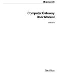
Figure 5-1
Continued
The following diagram shows the relationship between CL events and
execution of an X-side application that hibernates. It will be useful to refer
to this diagram while reading the remainder of this section.
Relationship of CL Events and X-side Hibernation
CL
CL Active
Initiate_Task
CL Suspended
Application id
CL Active
CL Active
CL Suspended
CL Suspended
(Application id)
CL Suspended
Hibernation
Application Code
EXEC DDA HIBERNATE EVENT
Hibernation
Activate_Task
(Application id)
CL Active
CL Active
EXEC DDA INITIALIZE
Initialize, Resolve External
References, etc.
EXEC DDA HIBERNATE EVENT
Activate_Task
CL Active
CL Active
X-side
Application
Application Code
EXEC DDA HIBERNATE EVENT
Terminate_Task
(Application id)
Termination Code
EXEC DDA TERMINATE
CL Active
38
Hibernation
Application ModuleX User Guide
54125
5/96
5.2
CL Support
Supporting functions
The following background CL calls are available in the AMCL06 set in
LCN release R431 and later:
• AMCL06$Initiate_Task—Initiates an OpenDDA application capable of
hibernating and receiving background CL events.
• AMCL06$Activate_Task—Sends an activate event to a CL-initiated
hibernating OpenDDA application.
• AMCL06$Terminate_Task—Sends a terminate event to a CL-initiated
hibernating OpenDDA application, providing a graceful shutdown of the
application.
• AMCL06$Get_Hiber_Task_Status—Obtains the current status of a CLinitiated hibernating OpenDDA application capable of receiving
background CL events.
Continued on next page
5/96
Application ModuleX User Guide
39
5.2
CL Support ,
Initiate_Task
Continued
The background CL subroutine AMCL06$Initiate_Task is used to initiate a
new instance of an OpenDDA application. After the call is made, the
background CL suspends execution and enters a wait condition until the
OpenDDA application has initiated and entered hibernation. The user
provides an application name, and once the application has entered
hibernation, a unique application id is returned to the CL block. The CL
should store this application id in a CDS parameter or other point.parameter
and then complete the execution of the CL block. The application id
returned from the subroutine is needed to subsequently activate
(AMCL06$Activate_Task) and terminate (AMCL06$Terminate_Task) the
application.
Syntax of the AMCL06$Initiate_Task subroutine:
SUBROUTINE AMCL06$Initiate_Task
(Ret_Status
: OUT NUMBER;
Det_Status
: OUT NUMBER;
Appl_ID
: OUT STRING;
Cmd_Line
: IN STRING;
X_Task_Timeout
: IN TIME;
Req_Timeout
: IN TIME)
-------
Return status of the call
Detailed return status
Application identifier
X-side application command line
X-side timeout value
LCN-side timeout value
Refer to Appendix I of the CL/AM Reference Manual for more information
about the functionality of the call and for definition of the arguments.
Activate _Task
The background CL subroutine AMCL06$Activate_Task is used to send an
activate event to a CL-initiated hibernating OpenDDA application. After the
call is made, the background CL suspends execution and enters a wait
condition until the OpenDDA application receives and processes the event,
presumably executes for a while, and subsequently returns to hibernation.
The user provides an application id (obtained from AMCL06$Initiate_Task)
and an event string which is passed to the OpenDDA application.
Syntax of the AMCL06$Activate_Task subroutine:
SUBROUTINE AMCL06$Activate_Task
(Ret_Status
: OUT NUMBER;
Det_Status
: OUT NUMBER;
Appl_ID
: IN STRING;
Event_String
: IN STRING;
X_Task_Timeout
: IN TIME;
Req_Timeout
: IN TIME)
-------
Return status of the call
Detailed return status
Application identifier
String passed to application
X-side timeout value
LCN-side timeout value
Refer to Appendix I of the CL/AM Reference Manual for more information
about the functionality of the call and for definition of the arguments.
Continued on next page
40
Application ModuleX User Guide
5/96
5.2
CL Support,
Terminate_Task
Continued
The background CL subroutine AMCL06$Terminate_Task is used to send a
terminate event to a CL-initiated hibernating OpenDDA application. This
provides a graceful shutdown of a hibernating OpenDDA application. After
the call is made, the background CL suspends execution and enters a wait
condition until the OpenDDA application has received and processed the
event, and terminated its execution. The user provides an application id
(obtained from AMCL06$Initiate_Task) and an event string which is passed
to the OpenDDA application.
Syntax of the AMCL06$Terminate_Task subroutine:
SUBROUTINE AMCL06$Terminate_Task
(Ret_Status
: OUT NUMBER;
Det_Status
: OUT NUMBER;
Appl_ID
: IN STRING;
Event_String
: IN STRING;
X_Task_Timeout
: IN TIME;
Req_Timeout
: IN TIME)
-------
Return status of the call
Detailed return status
Application identifier
String passed to application
X-side timeout value
LCN-side timeout value
Refer to Appendix I of the CL/AM Reference Manual for more information
about the functionality of the call and for definition of the arguments.
Continued on next page
5/96
Application ModuleX User Guide
41
5.2
CL Support,
Get_Hiber_Task_
Status
Continued
The background CL subroutine AMCL06$Get_Hiber_Task_Status is used
to obtain specific information about a single entry in the X-side hibernating
queue. It can be used to obtain information about a known application or to
get information about a current hibernating task in the hibernating queue to
display on a schematic.
To obtain information about a known application, this subroutine accepts as
input an application id (obtained from AMCL06$Initiate_Task) of an
OpenDDA hibernating application. It will return information about the
hibernating application, including the associated index number in the
hibernating queue.
To get information about a current hibernating task in the hibernating queue
to display on a schematic, this subroutine accepts as input an index
identifier. It will return information about the hibernating application for the
given index in the hibernating queue.
The following is the syntax of the AMCL06$Get_Hiber_Task_Status
subroutine:
SUBROUTINE AMCL06$Get_Hiber_Task_Status
(Ret_Status
: OUT NUMBER;
-Det_Status
: OUT NUMBER;
-Task_Status
: OUT NUMBER;
-Cmd_Line
: OUT STRING;
-Point_Name
: OUT STRING;
-Block_Name
: OUT STRING;
-Time_Initiated
: OUT TIME;
-Time_Activated
: OUT TIME;
-Appl_Priority
: OUT NUMBER;
-X_PID
: OUT NUMBER;
-Appl_ID
: IN OUT STRING; -Index
: IN OUT NUMBER; -Req_Timeout
: IN TIME)
--
Return status of the call
Detailed return status
hibernating or running
X-side application command line
Point initiating X-side application
CL name initiating X-side application
HP-UX time application initiated
HP-UX time application last activated
current HP-UX priority
X-side process identifier
X-side application identifier
Index into X-side hibernating queue
LCN timeout value
Refer to Appendix I of the CL/AM Reference Manual for more information
about the functionality of the call and for definition of the arguments.
42
Application ModuleX User Guide
5/96
5.3
OpenDDA Support
Supporting function
The OpenDDA Execution Statement HIBERNATE EVENT causes the
application to suspend execution awaiting an event initiated from CL. The
application suspends execution during execution of the HIBERNATE
EVENT statement, before the event data and status are returned. Either of
the CL calls AMCL06$Activate_Task or AMCL06$Terminate_Task can
cause the application to leave hibernation and resume execution. When the
application resumes execution, it completes the HIBERNATE EVENT
statement execution and returns and event data and status to the application.
Syntax:
EXEC DDA HIBERNATE EVENT,
EVENT_DATA=evt_data,
STATUS=exec_status;
evt_data
The variable evt_data is a structure that returns information to the
application as it exits hibernation as a result of an AMCL06$Activate_Task
or AMCL06$Terminate_Task call and resumes execution of code. The
information returned is listed in the following table.
Table 5-1
Event Data Structure
Field
Reference
5/96
Description
event_type
An integer code that represents the type of the event
(ACTIVATE, TERMINATE, or NO_EVENT)
event_status
The status associated with the event function
point_name
The entity that initiated the wakeup call
event_block
Name of the block that activated/terminated the
application
init_block
Name of the block that initiated the application
event_time
The HP-UX time when the event occurred
init_time
The LCN time when the application was initiated
event_string
The CL event string
For more information about the EXEC DDA HIBERNATE EVENT call, refer to
Section 6 of the OpenDDA Reference Manual.
Application ModuleX User Guide
43
5.4
X-Side Support Tools
Introduction
Two of the utilities provided by Honeywell in the HP-UX directory
/opt/TDC_Open/common/bin are used to enable the user to view
information about all CL-initiated X-side applications and kill any of these
applications—particularly useful for those in hibernation. The two utilities
are:
• display_appls
• kill_appls
display_appls
This is a command line tool used to obtain specific information about all
CL-initiated X-side applications. By default, it will display a short version
of output, although an option [-l] allows display of additional information.
Syntax:
display_appls [-l]
Applications are listed in two categories:
• SYNCHRONOUS APPLICATIONS WITH TERMINATION—Lists
tasks initiated by AMCL06$Execute_Task_With_Wait
• SYNCHRONOUS APPLICATIONS WITH HIBERNATION—Lists
tasks initiated with AMCL06$Initiate_Task
For each task listed, the following information is displayed:
• command line
• initiating point name
• initiating CL block name
• application status (hibernating or running)
• HP-UX process id
When the long version is requested by using the -l option, the following is
also displayed:
• application id (for hibernating applications only)
• time initiated
• time activated (for hibernating applications only)
• current HP-UX priority
For additional information about this utility, see Appendix I of the CL/AM
Reference Manual.
Continued on next page
44
Application ModuleX User Guide
5/96
5.4
X-Side Support Tools,
kill_appls
Continued
The X-side tool kill_appls is a command line tool used to abort CLinitiated X-side applications. It can only be executed by a user while a
member of the “axm” group This tool can kill
• one or all CL-initiated X-side applications associated with a point,
• one or all instances of the same application name, or
• applications that are either running or hibernating.
The tool is especially useful for killing X-side applications that can
hibernate, because an application that is in hibernation cannot be killed by
aborting the CL or inactivating the point to which the CL is attached.
Syntax:
There are two ways to invoke this tool. One way is to specify the
application name, and the other way is to specify the associated point.
The syntax when specifying the application name is
kill_appls -A application_name {-i application_id | -p process_id | -a}
The syntax when specifying the point name is
kill_appls -P point_name {-i application_id | -p process_id | -a}
One of the following three switches is required:
-i application_id Application identifier assigned when the
application is initiated by the
AMCL06$Initiate_Task call.
-p process_id
HP-UX process id.
-a
If used with the application_name
argument, all executions of the application
will be aborted. If used with the
point_name argument, all X-side
applications associated with the point will be
aborted.
NOTE: All options are case-sensitive.
For additional information about this utility, see Appendix I of the CL/AM
Reference Manual.
5/96
Application ModuleX User Guide
45
46
Application ModuleX User Guide
5/96
Section 6 – Configuration of Data Access Priority
6.1
Introduction
ATTENTION
This feature requires AXM release R200.
AXM services
There are a number of services available in the AXM. These included Data
Access and File Access. Some of these services can take very long periods
of time to complete an associated action. To ensure that resources are
available for high priority control actions, Honeywell has added
functionality in AXM release R200 that allows the user to configure Data
Access priority.
Application class
There are two basic classes of applications:
• High priority control applications.
• Low priority information level applications
High priority control
applications
These control applications often have stringent timing requirements for
reading and writing LCN data. They are involved in closed loop control
strategies and often, but not always, transfer smaller amounts of data.
Therefore, they need access to the LCN for bringing in reasonable amounts
of data, but the "path to the valve" must be available when needed.
Low priority information
level applications
These applications typically have more relaxed requirements for access to
the LCN for reading/writing of data. They tend to bring in a large amounts
of data for functions such as data collection (TPH), PC desktop viewing
(PCDE), or background types of applications. These are not control
applications, can often tolerate a little more variability in their access to the
LCN, and often do not write any data back to the LCN. These applications
can therefore take a great deal of time to complete actions and use a great
deal of channels and memory in the AM-side of the AXM to serve the large
data access requests.
Continued on next page
5/96
Application ModuleX User Guide
47
6.1
Introduction,
Continued
Configuration goals
The configuration functionality is provided to allow the user to “tune”
certain configuration settings to match up with the mix of application types
executing in an AXM. The following are the ultimate goals:
• Assure a clean "path to the valve" for the control applications coexisting
in the same AXM with applications used for gathering data for
information applications.
• Do not allow any type of platform service that can take very long period
of time (like File Services) to be able to block control application
requests.
• Provide sufficient low priority resources so that low priority requests are
not blocked out indefinitely.
Resources
There are two resources that the user can manage:
• Data access channels
• Data access servers
Data access channels
There are only a limited number of channels available for interfacing
between the AM-side and X-side. You must assure that a portion of these
resources are set aside for use by control applications when needed.
In an AXM with control applications coexisting with a large number of
noncontrol applications, the potential exists for the noncontrol applications
to consume all the available channels, use them for long time period tasks,
and therefore lock out control applications from running within an
allowable, deterministic, and repeatable time period.
To ensure that this will not happen, AXM R200 will allow the user to
configure the AXM to set aside a defined number of the data access
channels for high priority actions only. Then the only contention for these
channels will be between high priority control applications (such as
OpenDDA programs running at Control and RCasEnb data priority levels).
Low priority tasks will then have to share the remaining channels with other
noncontrol applications (for example, PCDE, OpenDDA programs running
at NoControl Data Priority levels, TPH collectors, and programs using
platform file services).
Continued on next page
48
Application ModuleX User Guide
5/96
6.1
Introduction,
Data access servers
Continued
The second resource to manage is the data access servers (and associated
AM-side pool memory used during the execution of these requests). Even
when applications are prioritized as high or low for determination of access
to data access channels, we must then be concerned about priority with
multiple queued requests against the data access servers. To support this,
AXM R200 will allow the user to configure the AM-side to set aside a
defined number of data access servers to service high priority requests only.
In addition, requests from the X-side can make data access requests with an
associated priority. The result is that even within the scope of high/low
classes, there is the capability to allow priorities within these classes. For
example, OpenDDA NoControl applications have a higher priority within
the low class of requests than, for example, an application such as PCDE.
Therefore, if a large number of requests are being queued for data access,
the servers will take care of the OpenDDA applications first. This allows for
some level of "jumping to the front of the line" within the priority classes.
Summary
5/96
AXM R200 allows a user to customize an AXM’s data access priority. The
user can ensure that a defined number of channels, data access servers, and
corresponding pool memory, have been set aside to service high priority
requests. The result is that after a node has demonstrated a defined
operational characteristic for various load configurations, the user can have
a good sense of assurance that this will be repeatable behavior. This will be
the case even if, for example, a large number of PC desktop users should
decide to call up Excel spreadsheets that use PCDE for access to LCN data,
and thereby demand a great deal of AXM resources.
Application ModuleX User Guide
49
6.2
The xdaconfig Configuration Tool
Files
The configuration of the priority of the Data Access paths through the Xlayer are defined in a configuration file xdapriority.cfg that is located in
/etc/opt/TDC_Open/common. The configuration file defines the number of
channels reserved for high priority requests as opposed to low priority
requests. The file also defines the number of Data Access servers assigned
to high priority requests as opposed to low priority requests. As shipped
from Honeywell in the AXM, the xdapriority.cfg file is set to four high
priority DA servers and 10 high priority channels. For UXS, the file is set
to zero for both high priority servers and channels.
Configuration tool
A configuration tool is provided to adjust these two priority related
configuration items. The tool, xdaconfig, is in the directory
/opt/TDC_Open/common/bin. The tool is a command line tool that asks the
user for the number of channels reserved for high priority requests (0 to 20)
and for the number of Data Access servers reserved for high priority
requests (0 to 4). The remaining channels and Data Access servers are then
assigned to low priority.
Discussion
For security, the configuration file is not a text file. In addition, the
configuration file and the configuration tool have their access restricted to
system administrators only (root level).
Low priority requests cannot be serviced by a high priority queue or by a
high priority Data Access serve; however, high priority requests can be
serviced by a low priority queue and servers. Therefore, if no DA servers
are configured for high priority, setting the number of high priority
channels to the minimum (0) and the number of Data Access servers to a
minimum (0) effectively sets all the DA servers to service both high and low
priority requests with the requests prioritized within a single queue.
ATTENTION
Whenever the configuration file is changed, the LCN personality must be
reloaded or the entire AXM must be restarted in order for the changes to
take effect.
Continued on next page
50
Application ModuleX User Guide
5/96
6.2
The xdaconfig Configuration Tool,
Sample session
Continued
The following is a sample session utilizing the Data Access configuration
tool.
$ cd /opt/TDC_Open/common/bin
$ xdaconfig
***
THE CURRENT DATA ACCESS CONFIGURATION ARE
Number of DA servers for HIGH
Number of channels reserved for HIGH
***
= 4
= 10
Do you want to update the configuration file? (Y or N) Y
Please enter the number of DA servers for ‘HIGH’ priority (0 to 4 or N) 3
Please enter the number of channels reserved for ‘HIGH’ priority (0 to 20 or N) 8
---
THE UPDATED DATA ACCESS CONFIGURATION ARE --Number of DA servers for HIGH
= 3
Number of channels reserved for HIGH
= 8
DA CONFIGURATION COMPLETE
$
5/96
Application ModuleX User Guide
51
52
Application ModuleX User Guide
5/96
Index
$
Data Definition and Access 2
DATACHNG schematic 27, 28
DDA 2
display_appls 44
$RCVCNT(n) 27, 32
$RCVSTA(n) 27, 30
$XACCESS 18
$XMITCNT(n) 27, 35
$XMITSTA(n) 27, 34
F, G
A, B
about audit files. 14
AMCL06 18
AMCL06$Activate_Task 39, 40
AMCL06$Get_Hiber_Task_Status 39, 42
AMCL06$Initiate_Task 39, 40
AMCL06$Terminate_Task 39, 41
Application ModuleX Architecture
Chassis types 4
Coprocessor hardware 6
Coprocessor software 6
Five-Slot Module configuration 4
Function of components 5
Ten-Slot Module configuration 4
axm group 17
AXMPERF schematic 27
C
File system
Configuration files discussion 23
Continued on next page 25
Data files 24
Discussion 21
Executables 25
Modified HP-UX files 26
Reference configuration files 23
Summary of key directories 22
Working configuration files 24
Function of AXM components 5
H
Hibernation 37
Advantages 37
CL Support 39
OpenDDA Support 43
HP-UX 6
I, J
chacl 13
chgrp 13
chmod 13
chown 13
Components of the AXM 5
configuration files 23
Configurations
Expanded network configuration 10
Minimum network configuration with MP–
AMXST1 workstation 9
Minimum network configuration with UXS 8
Standalone coprocessor 7
Where to find more information 11
control domain 2
coprocessor 6
information domain 2
K, L, M, N
kill_appls 45
O
OpenDDA 2
OpenUSE 2
D, E
Data Access Priority 47
Introduction 47
xdaconfig 50
5/96
Application ModuleX User Guide
53
Index
P, Q, R
xdapriority.cfg 50
PA-RISC 6
Performance measurement
Accessing the parameters from the LCN side 27
AXMPERF schematic 28
Custom schematic 28
DATACHNG schematic 28
Introduction 27
Programming example 29
Plant Information Network 2
Processor Status Data Point 27
PSDP 27
S
security 13
Physical 15
Procedural 15
Security—HP-UX
Audit Files 14
File permissions 13
important categories 13
Introduction 13
Network security 14
User security 14
Security—LCN
AXM failover to AM 16
Directory for CL-initiated applications 17
Function of XACCES 19
Overview 16
The global X-access switch 18
Topics to be covered 16
Using test data with OpenDDA 17
T, U, V
TotalPlant 1
W
WSI2 board 6
X, Y, Z
X Windows environment 3
X-access switch 18
XACCES external load module 19
xdaconfig 50
Sample session 51
54
Application ModuleX User Guide
5/96
READER COMMENTS
Honeywell's IAC Automation College welcomes your comments and suggestions to improve future editions
of this and other publications.
You can communicate your thoughts to us by fax, mail, or toll-free telephone call. We would like to
acknowledge your comments; please include your complete name and address.
BY FAX: Use this form and fax to us at (602) 313-4108.
BY TELEPHONE: In the U.S.A., use our toll-free number 1*800-822-7673 (available in the 48
contiguous states except Arizona; in Arizona dial 1-602-313-5558).
BY MAIL: Use this form; detach, fold, tape closed, and mail to us.
Title of Publication:
Publication Number:
Writer:
Application ModuleX User Guide
Issue Date:
AX09-200
Jim Kennedy
COMMENTS: ___________________________________________________________
_______________________________________________________________________
_______________________________________________________________________
_______________________________________________________________________
_______________________________________________________________________
_______________________________________________________________________
_______________________________________________________________________
_______________________________________________________________________
RECOMMENDATIONS:___________________________________________________
_______________________________________________________________________
_______________________________________________________________________
_______________________________________________________________________
_______________________________________________________________________
_______________________________________________________________________
_______________________________________________________________________
_______________________________________________________________________
NAME ________________________________________________ DATE ___________
TITLE _________________________________________________________________
COMPANY _____________________________________________________________
ADDRESS ______________________________________________________________
CITY _________________________________ STATE ___________ ZIP ___________
(If returning by mail, please tape closed; Postal regulations prohibit use of staples.)
5/96
Communications concerning technical publications should be directed to:
Automation College
Industrial Automation and Control
Honeywell Inc.
2820 West Kelton Lane
Phoenix, Arizona 85023
FOLD
FOLD
From:
NO POSTAGE
NECESSARY
IF MAILED
IN THE USA
FIRST CLASS
PERMIT NO. 4332
Cut Along Line
BUSINESS REPLY MAIL
PHOENIX, ARIZONA
POSTAGE WILL BE PAID BY ....
Honeywell
Industrial Automation and Control
2820 West Kelton Lane
Phoenix, Arizona 85023
Attention: Manager, Quality
FOLD
Additional Comments:
FOLD
Industrial Automation and Control
Honeywell Inc.
16404 North Black Canyon Highway
Phoenix, Arizona 85023-3033
L
Helping You Control Your World
Industrial Automation and Control
Honeywell Inc.
16404 North Black Canyon Highway
Phoenix, Arizona 85023-3033
L
Helping You Control Your World