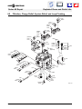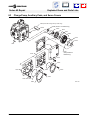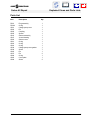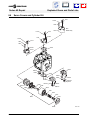
1
CONTENTS
saue
Series 42
Axial Piston
Pumps
Repair Manual
CONTENTS
saue
Series 42 Repair
Introduction
1. Introduction
1.1
Using This Manual
This manual provides "Major Repair" procedures for
the Series 42 variable displacement pumps.
Minor Repairs are those which can be performed
without removing the side cover. These repairs may
be performed without affecting the unit warranty and
are outlined in the Series 42 Service Manual (BLN10093).
Major Repairs are those repairs that require the
removal of the side cover. These repairs are to be
performed only by Sauer-Sundstrand Authorized Service Centers and / or original equipment manufacturers who have been adequately trained by SauerSundstrand to perform these repairs.
1.2
Performing major repairs on the Series 42 products
may affect the unit warranty status, thus the factory
should be consulted prior to undertaking such repairs.
These repair procedures, when used in conjunction
with the procedures in the Series 42 Service Manual,
provide complete service and repair information for
Series 42 products. It is necessary to have the
Service Manual on hand to complete major repairs.
Safety Precautions
Always consider safety precautions before beginning a service procedure. Protect yourself and others from injury.
The following general precautions should be taken into consideration whenever servicing a hydrostatic system.
Loss of Hydrostatic Braking Ability
WARNING
When Series 42 units are used in vehicular
hydrostatic drive systems, the loss of hydrostatic drive line power in any mode of operation (e.g. acceleration, deceleration or “neutral” mode) may cause a loss of hydrostatic
braking capacity. A braking system which is
independent of the hydrostatic transmission
must, therefore, be provided which is adequate
to stop and hold the system should the condition develop.
Disable Work Function
WARNING
Certain service procedures may require the
vehicle / machine to be disabled (wheels raised
off the ground, work function disconnected,
etc.) while performing them in order to prevent
injury to the technician and bystanders.
Copyright 1997, Sauer-Sundstrand Company.
All rights reserved. Contents subject to change. Printed in U.S.A.
F100 003
2
Fluid Under High Pressure
WARNING
Use caution when dealing with hydraulic fluid
under pressure. Escaping hydraulic fluid under pressure can have sufficient force to penetrate your skin causing serious injury. This
fluid may also be hot enough to burn. Serious
infection or reactions can develop if proper
medical treatment is not administered immediately.
Flammable Cleaning Solvents
WARNING
Some cleaning solvents are flammable. To
avoid possible fire, do not use cleaning solvents in an area where a source of ignition may
be present.
Personal Safety
WARNING
Proper safety equipment, including safety
glasses, should be used at all times.
CONTENTS
saue
Series 42 Repair
Introduction
Contents
1. Introduction .................................................................................................................................................2
1.1 Using This Manual ................................................................................................................................ 2
1.2 Safety Precautions ...............................................................................................................................2
1.3 Symbols Used in Sauer-Sundstrand Literature .................................................................................... 4
1.4 Ordering Replacement Parts and Service ............................................................................................ 4
2. General Instructions ................................................................................................................................... 5
3. Disassembly ................................................................................................................................................ 6
4. Subassembly Repair and Inspection ...................................................................................................... 12
4.1 Cylinder Kit ......................................................................................................................................... 12
4.2 Servo Piston ....................................................................................................................................... 14
4.3 Valve Plate and Servo Covers ............................................................................................................ 17
4.4 Shaft Assembly ................................................................................................................................... 18
4.5 Swashplate and Swashplate Bearings ............................................................................................... 19
4.6 Charge Pump Group .......................................................................................................................... 20
4.7 Charge Pump Cover, Seal Carrier, and Control Linkages .................................................................. 21
5. Reassembly ...............................................................................................................................................22
6. Exploded View Parts Drawings ................................................................................................................ 32
6.1 Shaft Options ......................................................................................................................................32
6.2 Filtration, Charge Relief, System Relief, and Loop Flushing .............................................................. 34
6.3 Charge Pump, Auxiliary Pads, and Servo Covers .............................................................................. 36
6.4 Control Options .................................................................................................................................. 38
6.5 Servo Piston, Swashplate, and Bearings ........................................................................................... 40
6.6 Servo Covers and Cylinder Kit ........................................................................................................... 42
6.7 Nameplate .......................................................................................................................................... 43
3
CONTENTS
saue
Series 42 Repair
1.3
1.4
Introduction
Symbols Used in Sauer-Sundstrand Literature
DANGER! May result in injury.
Lubricate with hydraulic fluid.
May result in immediate or premature damage.
Apply grease / petroleum jelly.
Reusable part
Apply locking compound.
Nonreusable part, use a new part.
Inspect for wear or damage.
Non-removable item
Clean area or part.
“OR” in drawing – either option may exist.
Be careful not to scratch or damage.
Measurement required.
Note correct orientation.
Flatness specification
Mark orientation for reinstallation.
Parallelism specification
Torque specification
External hex
Press in.
Internal hex
Pull out with tool.
Torx head
Use installation sleeve / cone (bullet).
Ordering Replacement Parts and Service
To ensure the best performance, order genuine SauerSundstrand replacement parts. See BLN-2-41668
(28 cc) or BLN-2-41691 (41 cc) for listings of available
service parts and service kits for Series 42 units.
To order parts, contact Sauer-Sundstrand Extended
Customer Service (ECS) at (515) 239-6078, fax
(515) 239-6230, or your nearest Authorized Service
Center.
Some service parts may be available only in kits,
while other parts may be available on an individual
basis.
Sauer-Sundstrand provides a complete repair service for its products. Contact any Sauer-Sundstrand
Authorized Service Center for details. Sauer-Sundstrand Authorized Service Center locations are listed
in BLN-2-40527, or Publication SAW (Id. No. 698266).
4
CONTENTS
saue
Series 42 Repair
General Instructions
2. General Instructions
Remove the Pump!
Inspect for System Contamination!
Prior to performing major repairs on the Series 42
pump, remove the pump from the vehicle. Chock the
vehicle to prohibit movement. Be aware that hydraulic fluid may be under high pressure and / or hot.
Inspect the outside of the pump and fittings for
damage.
Inspect the pump for system contamination. If contamination is found, or is known to be present, all
components of the pump should be fully disassembled,
cleaned, and inspected using Series 42 Service
Manual (BLN-10093) in conjunction with this manual.
Replace the O-rings and Gaskets!
Mark the Orientation!
Using a permanent or dye marker, mark the side of
the housing that has the neutral adjustment tie bolt
(G053) sticking out, as illustrated below. Make the
mark directly on the housing (not the servo cover).
Keep it Clean!
Cleanliness is a primary means of assuring satisfactory pump life, on either new or repaired units. Clean
the outside of the pump thoroughly before disassembly. Take care to avoid contamination of the system
ports. Cleaning parts by using a clean solvent wash
and air drying is usually adequate.
As with any precision equipment, all parts must be
kept free of foreign materials and chemicals. Protect
all exposed sealing surfaces and open cavities from
damage and foreign material. If left unattended, the
pump should be covered by a protective layer of
plastic.
It is recommended that all O-rings and gaskets be
replaced. Lightly lubricate all O-rings with clean petroleum jelly prior to assembly.
Lubricate all Moving Parts!
During reassembly, all parts which have relative
motion between two surfaces should be coated with
a film of clean hydraulic oil. This will help to lubricate
these surfaces during start-up. For fluid quality requirements, refer to bulletin BLN-9887.
Orient the Pump!
For major repair, place the transmission in a stable
position with the input shaft pointing upwards, as
illustrated above. It may be necessary to secure the
pump to prevent personal injury and allow bolts to be
adequately torqued.
Front Face
Left Face
Top Face
Bottom Face
Right Face
Rear Face
E100 110E
Pump Face Orientations
5
CONTENTS
saue
Series 42 Repair
Disassembly
3. Disassembl
1. Remove the 'B' Pad Cover Plate (4.5 in. dia.,
G085, p. 11) or Auxiliary Pump, if Present.
Note: Record or mark the auxiliary pump or 'B'
pad cover plate orientation for reassembly
purposes. 'A' pad cover plate (3.5 in. dia.)
removal is not necessary for major repair.
Remove the auxiliary pump or 'B' pad cover plate
bolts (2) using a 3/4 in. hex wrench or 3/8 in. internal
hex wrench.
F091
Remove the O-ring from the auxiliary pump or cover
plate.
2. Remove the Case Drain Plug.
Using a 9/16 in. internal hex wrench (28 cc) or a 5/8
in. internal hex wrench (41 cc), remove the case drain
plug (F091) or corresponding hose to relieve the
formed vacuum that may prevent the removal of the
input shaft.
3. Remove the Seal Carrier Retaining Ring.
Rotate the pump so that the input shaft points upwards.
Use a flat head screwdriver to remove the seal carrier
retaining ring (F096). Some earlier production models may contain an internal snap ring that requires a
large pair of internal snap ring pliers for removal.
28 cc: 9/16 in.
41 cc: 5/8 in.
E100 114
Unit in Upright Position
F096
C020
Screwdriver Pry
Point
C017
4. Remove the Seal Carrier Assembly.
It may be necessary to use a flat head screwdriver
along the raised surface of the seal carrier to remove
the seal carrier assembly (C020) as shown at right.
Since only friction is holding the input shaft in place,
it may be possible (but difficult) to ease seal carrier
removal by lifting on the shaft.
It is advised that the shaft lip seal (C018, p. 21) be
replaced on all major repairs. Press the seal from the
carrier. Remove and discard as outlined on page 21.
Remove and discard the O-ring (C017) from the seal
carrier or housing.
6
E100 115E
Seal Carrier Removal
CONTENTS
saue
Series 42 Repair
Disassembly
5. Remove the Shaft Assembly.
Grip the splines of the input shaft and lift the shaft
assembly from the unit.
6. Remove the Side Cover Bolts.
The six (6) side cover bolts (F007) may be removed
using a Torx T-30 wrench.
Shaft Assembly
7. Remove the Side Cover.
The side cover may be press fit to the housing and
(F2) contains swashplate bearings that are under
load. To remove the side cover, it is necessary to
press the swashplate down using the handle of a
clean rubber mallet as illustrated at right. Apply force
towards the center of the pump on the side cover end
of the swashplate. If the side cover does not disengage from the housing, it may be necessary to first tap
the side cover with a dead blow as indicated at right
to separate the side cover from the gasket.
E100 116E
Shaft Removal
Push
Rubber
Mallet
F008
F2
F007
Dead
Blow
Point
T-30
Dead Blow
Point
E100 118E
Side Cover Removal
7
CONTENTS
saue
Series 42 Repair
Disassembly
8. Remove the Cylinder Kit.
Lift the exposed end of the swashplate (B011) and
slide the cylinder kit (N001) from the housing.
Note: Be careful not to scratch or damage the
top or bottom surface of the cylinder kit. Place
the cylinder kit in a clean environment.
9. Remove the Swashplate.
To remove the swashplate (B011) through the side
cover opening it is necessary to tilt the swashplate at
an angle as it is pulled from the swashplate needle
bearing (B010).
Lift
B011
N001
10. Remove the Swashplate Needle Bearing Assembly.
Reach through the side cover opening and slide the
swashplate needle bearing and carrier (B010) from
the servo piston bearing cavity. It may be necessary
to rotate the servo piston (G100, p. 10) so that the
bearing may be removed.
11. Remove the Valve Plate.
Lift the valve plate (N006) from the housing. It may be
necessary to use a small flat head screwdriver to
loosen the valve plate from the pump housing.
Note: Be sure not to scratch or damage either
surface of the valve plate. Be careful not to nick
the valve plate when it breaks loose from the
housing. Place the valve plate in a clean environment.
12. Remove the Valve Plate Timing Pin.
The valve plate timing pin (F006) is located at the
bottom of the side cover interface. Slide the pin out of
the housing.
E100 119E
Cylinder Kit Removal
B010
B011
E100 120
Swashplate Removal
Note: It is easy to confuse the valve plate
timing pin and gerotor cover orientation pin
(G065, p. 11). The timing and orientation pins
are dimensionally identical, except in length.
The valve plate timing pin length is 15.89 mm
(0.625 in.) and the gerotor cover orientation
pin measures 12.70 mm (0.500 in.). Do not
interchange these pins on reassembly!
N006
F006
Valve Plate Removal
8
E100 121
CONTENTS
saue
Series 42 Repair
Disassembly
D082
D081
Step 13, Control and Control Linkage Removal,
is not necessary unless the servo piston is
going to be removed or the unit has experienced contamination.
13. Control and Control Linkage Removal
FNR and NFPE Controls, page 38.
FNR (D004; electric three position) and NFPE (D060;
non-feedback proportional electric) style controls do
not need to be removed for major repair unless
contamination is suspected (see Series 42 Service
Manual, BLN-10093 for more information).
T-30
D003
D002
T-30
3/16 in.
D080
D070
E001
Manual and Electrical Displacement Controls.
For MDC (D070) models, remove the alignment plug
(D003) using a 3/16 in. internal hex wrench.
MDC and EDC (D080) modules may be detached by
removing the seven (7) mounting bolts (D002, D081,
D082) with a Torx T-30 wrench. It may be necessary
to lightly tap on the steel body of the control with a
rubber mallet to loosen it from the housing.
Remove the control gasket (E001).
Note: The holes in the control gasket act as
regulating orifices. Refer to the appropriate
Service Parts List and your order code to
determine the correct replacement gasket.
The summing link (D011), feedback link (D012), and
neutral adjustment link (D013) must be removed.
Take note of the manner in which the parts are
assembled and the way in which the summing link
engages the control spool.
Remove the summing link by sliding it off the feedback link.
E100 112
Control Removal
D011
D010
D012
4 mm
D013
Remove the linkage pivot screw (D010) using a 4 mm
internal hex wrench.
Slide the feedback link towards the servo piston to
disengage the neutral adjustment link. All linkages
should now be removed.
E100 113
Control Linkage Removal
9
CONTENTS
saue
Series 42 Repair
Disassembly
14. Remove the Tie Bolt Side Servo Cover.
Remove the servo cover (M001) that does not have
the neutral adjustment tie bolt (G053) sticking out of
the center. Use a Torx T-30 wrench to remove the five
(5) servo cover bolts (L005). Also remove the servo
cover gasket (F009).
L005
M001
F009
T-30
L001
15. Remove the Servo Adjustment Seal Nut.
Using a 13 mm or 17 mm six point socket, remove and
discard the servo adjustment nut (G060). Use a 5 mm
or 7 mm hex wrench to hold the tie bolt (G053) for
removal.
Note: Once a servo adjustment seal nut has
been removed, it should be discarded and
replaced because it will lose its sealing properties.
16. Remove the Other Servo Cover and Piston.
Remove the five (5) servo piston bolts (L005) with a
Torx T-30 wrench. Pull the remaining servo cover
(L001) and attached servo piston (G100) from the
pump. After the servo cover and piston have been
removed from the pump, remove the servo cover
from the servo piston tie bolt (G053).
G053
5 mm
or 7 mm
E100 122
Servo Cover Removal
G052
F002
If none of the following statements are true, the
rest of section 3, Disassembly, may be skipped.
Otherwise continue with step 17.
•
The input shaft does not demonstrate
spalling from the rear needle bearing, as
illustrated on page 18.
•
•
No contamination has entered the pump.
The unit does not demonstrate any charge
pump problems.
17. Remove the Charge Pump Cover.
Rotate the pump so that the charge pump cover
(G001) is pointing upwards as illustrated on page 11.
Using a T-45 wrench, remove the seven (7) bolts
(G036, 6 bolts on 'B' pad units) that attach the charge
pump cover to the pump housing. It may be necessary to tap the cover with a rubber mallet to loosen it
from the housing.
18. Remove the Charge Pump Cover Gasket.
Remove and discard the charge pump cover gasket
(G030, p. 11).
10
G100
G060
B010
B013
13 mm
or 17mm
E100 123
Servo Piston Removal
CONTENTS
saue
Series 42 Repair
19. Remove the Gerotor Cover.
Two O-rings (G022, G023) accompany the gerotor
cover (G020) removal. Early models with an 'A' pad
option may contain a third O-ring (G021, p. 36).
20. Remove the Gerotor Assembly.
The gerotor assembly (G010) may remain in the
gerotor cover (G020) upon disassembly.
Disassembly
9/16 in.
3/4 in.
G090
G085
G036
G080
Units not containing an integral charge pump will not
have a gerotor assembly present.
21. Remove the Defeat Plug (no charge pump
units only).
Units without an integral charge pump may contain a
charge pump defeat plug (F020). Excluding early
production models, the defeat plug is tapped to use
an M6 threaded bolt for removal. All servo cover and
control bolts have an M6 thread. Remove by pulling
from the unit. Remove and discard the defeat plug Oring (F020A).
T-45
G001
G030
22. Remove the Drive Coupling and Drive Pin.
Remove the drive coupling (G005) from the pump.
Take care to not lose or drop the drive pin (G002) into
the unit.
G023
Some 41 cc units may contain a washer style spacer
(G005) under the drive coupling that requires removal.
G020
Units without an integral charge pump will not contain
a drive pin.
G010
23. Remove the Alignment and Orientation Pins.
Three pins are present at the interface. Two large
pins (G075) align the charge pump cover. A third and
smaller pin (G065) orients the gerotor cover. It is
possible that the gerotor orientation pin may remain
in the gerotor cover on removal. Units without charge
pumps will not contain the third (smaller) orientation
pin. It may be difficult to remove the pins due to a
vacuum formed in the cavity.
G022
F020A
G005
F020
G002
G075
G005
(Some 41 cc only)
G065
G075
Note: Be careful to not drop any of the pins into
the unit.
24. Remove the Shaft Needle Bearing.
As needed, press the shaft needle bearing (F002, p.
10) from the housing. If a press is not available, it is
possible to use an appropriately sized socket and
extension to press the bearing from the housing.
E100 111E
Charge Pump and Cover Removal
Protect the charge pump surface from damage during this procedure.
11
CONTENTS
saue
Series 42 Repair
Subassembly Repair and Inspection
4. Subassembly Repair and Inspection
4.1
Cylinder Kit
The cylinder kit (N001), also referred to as the 'rotating group', is comprised of nine (9) pistons, with a
swiveling brass 'slipper' attached to each piston. The
slipper retainer (F028) holds the pistons (F029) upright and aligned with the corresponding cylinder.
The slipper retainer pivots on a ball guide (F027)
which transfers the downward force of the slippers
and pistons to three hold down pins (F025). The hold
down pins then transfer the downward force to the
cylinder block spring (F022), and eventually to the
cylinder block (F020).
F029
F028
F027
F026
F025
Disassemble the Cylinder Kit.
Remove the pistons from the cylinder kit. The pistons
and bores are not selectively fitted, so it is usually not
necessary to replace the pistons in their original
bores. However, units with high hours may begin to
develop wear patterns, and it is advisable to replace
the pistons into the original bores if at all possible.
N001
F020
F021
Remove the ball guide (F027). The three hold down
pins (F025) may now be removed. A retainer ring
(F026) is used to hold the pins in the upright position.
Due to prior assembly, the retainer ring will be resting
at the bottom of the cylinder block (F020). It may be
necessary to use a packing hook to remove the ring.
F022
F023
F024
E100 124
Cylinder Kit Disassembly
Inspect the Cylinder Block.
First look at the bottom of the cylinder block (F020).
The running surface, or face which contacts the valve
plate, should be smooth and free of nicks and burrs.
No scratches or grooves noticeable to the touch are
allowed, as these may drastically affect the flow of the
unit. Running face flatness should be flat to 0.002 mm
(0.000079 in.) TIR convex for 28 cc and 41 cc cylinder
blocks. Maximum inside cylinder bore diameters
should be 14.30 mm (0.5631 in.) for 28 cc cylinder
blocks and 16.14 mm (0.6353 in.) for 41 cc cylinder
blocks. Minimum cylinder block height is 50.00 mm
(1.968 in.) for 28 cc blocks and 55.88 mm (2.200 in.)
for 41 cc blocks when measured as illustrated at right.
F020
Minimum
Cylinder Block
Height:
28 cc:
50.00 mm
1.968 in.
41 cc:
55.88 mm
2.200 in.
Running Face Flatness
28 cc:
41 cc:
Flat to 0.00201 mm TIR Convex
(Flat to 0.000079 in. TIR Convex)
Cylinder Block Minimum Height
12
P100 362E
CONTENTS
saue
Series 42 Repair
Inspect the Rotating Group Pistons / Slippers
Look for any discoloration on the pistons (F029).
Holding a white piece of paper behind each piston
helps to indicate discolorations. Discolored pistons
indicate that the unit was subjected to excessive
temperature and should not be reused. The slippers
may now be inspected for signs of excess wear or
damage. The minimum slipper foot thickness is 3.33
mm (0.131 in.) for 28 cc models and 3.68 mm (0.145
in.) for 41 cc models. Slipper end play should be
0.152 mm (0.006 in.) or less for 28 cc and 41 cc
models. Discard and replace all piston assemblies if
brass slippers are scored, excessively rounded at the
edges, or detached from the piston.
Subassembly Repair and Inspection
Maximum
End Play:
Minimum
Slipper Foot
Thickness:
28 cc:
3.33 mm
(0.131 in.)
41 cc:
3.68 mm
(0.145 in.)
Slipper
F029
E100 125E
Rotating Group Piston
If Needed, Fully Disassemble the Cylinder
Block.
Note: This step is not necessary for most
normal repairs and should not be performed
unless internal damage is suspected or the
pump has become contaminated (contamination may remain in the spring cavity). Be careful not to scratch or damage the cylinder block
during this process.
Compress the cylinder block spring (F022) and remove the spiral retaining ring (F024), outer washer
(F023), spring, and inner washer (F021). Visual inspection of the cylinder block, spring, and washers
should indicate minimal wear. Replace if cracks or
damage are present. Reassemble in the reverse
order.
Reassemble the Cylinder Kit.
A light coating of hydraulic fluid should be used to
coat all parts prior to reassembly. Place the retainer
ring (F026, p. 12) in the cylinder block (F020) so that
it sits approximately 1/8 in. below the top surface.
Insert the three hold down pins (F025) and make sure
that they sit squarely in their respective grooves.
Replace the ball guide (F027). Insert the slipper
retainer (F028) containing the slippers and pistons
(F029). Once the entire cylinder block has been
reassembled, check to be sure that the ball guide sits
squarely on all three pins. The retainer ring should
still remain approximately 1/8 in. below the top of the
cylinder block.
28 cc:
41 cc:
0.152 mm
(0.006 in.)
F020
F021
F022
F023
F024
E100 126
Cylinder Block Disassembly
E100 127
Assembled Cylinder Kit
Note: Be sure to install the slipper retainer
(F028) so that it mates correctly with the ball
guide (F027; concave side of the slipper retainer against the ball guide).
13
CONTENTS
saue
Series 42 Repair
4.2
Subassembly Repair and Inspection
Servo Piston
Inspect the Servo Piston.
Inspect the housing and housing servo bore to ensure no piston ring fragments were deposited during
servo piston removal. Remove and discard the piston
rings (G052) and O-rings (G051) from the servo
piston.
X2
G100
G053
G051
G052
Piston ring and O-ring installation procedures are
outlined in section 5, Reassembly.
Measure Servo Piston Torque to Turn
Check to see that the servo piston (G100) is correctly
adjusted. Holding the servo piston stationary in one
hand, measure the torque required to twist the neutral
adjustment tie bolt (G053) after break away. 28 cc
and 41 cc model servo piston tie bolts use a 5 mm and
7 mm hex wrench, respectively. The torque to turn the
tie bolt must be 0.23 Nm (2 in•lbf) and above for 28 cc
units, 0.68 Nm (6 in•lbf) and above for 41 cc units, and
1.13 Nm (10 in•lbf) or above models with NFP controls. The servo piston torque to turn must meet
the minimum specifications in each direction of
rotation.
13 mm or
17 mm
E100 135
Servo Piston Inspection
G059
13 mm or
17 mm
24 mm
G058
G057
G054
When testing the torque to turn, the large nut (G057)
is permitted to turn, but the upper spring guide (G054)
should not turn. This may be unavoidable in some
instances.
If the servo piston does not meet the above requirements, it is necessary to loosen the nuts and repeat
the adjustment procedure outlined in Adjustment of
Servo Piston Torque to Turn on page 16 until the
desired results are achieved. Several attempts may
be necessary before correctly setting the piston assembly.
G060
G055
G056
5 mm
or 7 mm
G053
G050
E100 156
Servo Piston Components
14
CONTENTS
saue
Series 42 Repair
Subassembly Repair and Inspection
Complete Piston Disassembly
Contamination or damaged parts may require
the complete disassembly of the servo piston.
It is not necessary to completely disassemble
the servo piston assembly if only torque to turn
adjustment is desired.
G059
13 mm or
17 mm
24 mm
Holding the tie bolt with a 5 mm or 7 mm wrench,
tighten the small nut until the spring compresses
enough to relieve all pressure from the snap ring
(G059).
Remove and discard the snap ring.
G057
G054
G055
Remove the nuts (G058, G060) from the tie bolt
(G053) using a 13 mm or 17 mm hex wrench and a 24
mm hex wrench.
Replace and hand tighten the small nut (G058).
G058
G056
5 mm
or 7 mm
G053
G050
Remove the spring assembly.
If necessary, disassemble the spring assembly. Remove the two nuts (G058, G057), upper and lower
spring guides (G054, G056), spring (G055), and tie
bolt (G053). NFP models may also contain shims that
must be reused during reassembly.
E100 156
Servo Piston Components
Wash all parts in a clean solvent wash and allow
them to air dry.
15
CONTENTS
saue
Series 42 Repair
Piston Reassembly
Place the lower spring guide (G056) on the tie bolt
(G053). Notice that the lower spring guide has a
distinguishing counter bore on one side.
Place the spring (G055) over the tie bolt.
Subassembly Repair and Inspection
G059
13 mm or
17 mm
24 mm
G058
G057
G054
Place the upper spring guide (G054) on the tie bolt.
Install the large servo nut (G057) on the tie bolt and
run it down by hand until it contacts the upper spring
guide. Hand tighten the nut against the upper spring
guide.
Run the small nut (G058) down the tie bolt until it
loosely contacts the large servo nut.
G055
G056
5 mm
or 7 mm
G053
Place the assembly into the servo piston body (G050).
Compress the piston assembly so that the snap ring
may be inserted. If a press is not available, it is
possible to compress the spring by tightening the
nuts on the tie bolt. It may be necessary to temporarily
insert a spacer between the top spring guide and
nuts.
Install a new snap ring (G059) into the piston.
Release the piston assembly from the compressed
position so that all of the pressure now lies on the
snap ring, and the tie bolt is free to spin.
Set the piston assembly on a flat surface with the tie
bolt pointing upwards.
Adjustment of Servo Piston Torque to Turn
Ensure that both nuts (G057, G058) are loose and the
entire spring load is resting on the snap ring.
Hold the large nut stationary using a 24 mm hex
wrench and hand tighten the tie bolt by turning the
stud CCW until it is finger tight.
While holding the large nut stationary, use a 5 mm or
7 mm hex wrench to tighten (CCW) the tie bolt until
the spring has just begun to compress.
Back off (CW) the the tie bolt approximately 1/16 turn.
This will serve as an approximation for setting the
servo piston torque.
While holding the large nut stationary with, torque the
smaller nut to 20-27 Nm (15-20 ft•lbf).
Measure servo piston torque to turn as outlined on
page 14. Readjust if torque specifications are not
met. When attempting fine adjustment, back the
small nut off slightly, turn both nuts on the tie bolt
(G053) together, and then retorque the small nut
while holding the large nut stationary.
16
G050
E100 156
Servo Piston Components
CONTENTS
saue
Series 42 Repair
4.3
Subassembly Repair and Inspection
Valve Plate and Servo Covers
Inspect the Valve Plate.
Valve plate thickness (N006) should be no less than
4.97 mm (0.196 in.) for 28 cc model valve plates and
3.86 mm (0.152 in.) for 41 cc model valve plates.
Appearance should be flat and smooth on both the
running face and the bottom. Parallelism for 28 cc
and 41 cc model valve plates should be 0.0249 mm
(0.00098 in.) or less. Valve plate flatness should
measure flat to 0.0038 mm (0.00015 in.) convex for
28 cc and 41 cc models. A magnetic particle inspection is recommended to detect cracks. Cracks are not
allowed on any surface of the part.
Run a fingernail or pencil tip across the diameter of
the sealing land surface (see illustration at right). No
deep or outstanding grooves are allowed, as these
may cause a decrease in pump flow. Lap (to within
specification) or replace if grooves or nicks are present.
Minimum Thickness:
28 cc: 4.97 mm (0.196 in.)
41 cc: 3.86 mm (0.152 in.)
Parallelism:
28 cc: 0.0249 mm (0.00098 in.)
41 cc: 0.0249 mm (0.00098 in.)
Flatness (maximum convex):
Flat to:
28 cc: 0.0038 mm (0.00015 in.)
41 cc: 0.0038 mm (0.00015 in.)
N006
P100 366E
Valve Plate Specifications
N006
Clockwise (CW) and counter-clockwise (CCW) valve
plate orientations are shown at right and may be
distinguished by the direction of the dominant 'fish
tails'.
Inspect the mating surfaces of the valve plate and
housing for any possible contamination, as even a
few thousandths of an inch of contamination may be
cause for low pump flow.
Inspect the Servo Covers.
Inspect the servo covers (M001, L001) to ensure that
the gasket mating surfaces are clean and smooth. No
scratches are allowed on the mating surfaces. Clean
as necessary. Discard and replace the servo cover
gaskets.
Sealing Land
Surface
P100 367E
Valve Plate Inspection
CCW
N006
CW
P100 372
Valve Plate Orientations
M001
L001
Tie
Bolt
Hole
Servo Cover Inspection
E100 134E
17
CONTENTS
saue
Series 42 Repair
4.4
Subassembly Repair and Inspection
Shaft Assembly
Inspect the Input Shaft.
Check to see that the input shaft (C001) and its
splines are straight and free of damage or heavy
wear. Inspect the shaft surface where it meets the
shaft seal. If a groove is formed that may let dirt into
or hydraulic fluid out of the unit, replace the shaft.
Inspect the surface where the rear shaft bearing
(F002, p. 24) contacts the shaft (see right). If spalling
is present, replace the shaft and rear shaft needle
bearing. Clean the sealing area with a nonabrasive
material, if necessary. Lubricate the shaft with a light
coating of hydraulic fluid.
C018
C001
E100 131
Input Shaft Inspection
Inspect the Shaft Roller Bearing.
Rotate the shaft roller bearing (C003) to check for
smoothness. If a contaminated or damaged bearing
is suspected, clean with a solvent and re-lubricate
with hydraulic fluid. If the problem is not remedied by
cleaning, replace the bearing.
If either the shaft or roller bearing are to be
replaced, disassemble and reassemble the
shaft assembly as outlined below.
C003
E100 132
Shaft Roller Bearing Inspection
Remove the Shaft Snap Ring.
Using a pair of external snap ring pliers, remove the
snap ring (C002) from the shaft (C001).
For reinstallation purposes, note the direction of the
chamfer on one side of the roller bearing (C003). The
chamfer (illustrated at right) should face the center of
the pump.
C002
C003
Chamfer
C001
Press the roller bearing from the shaft. Be sure to
press only on the inner race of the bearing to prevent
bearing damage.
Reassemble the Shaft.
Press the roller bearing (C003) on the shaft (C001) so
that the chamfer will eventually face the center of the
pump. Be sure to press only on the inner race of the
bearing.
Replace the shaft snap ring (C002) using a pair of
external snap ring pliers. Make sure that the snap ring
is fully seated in its respective groove.
18
E100 117E
Complete Shaft Disassembly
CONTENTS
saue
Series 42 Repair
4.5
Subassembly Repair and Inspection
Swashplate and Swashplate Bearings
Inspect the Three (3) Swashplate Bearings.
Do not remove the large swashplate needle bearings! They are non-serviceable items. The third
swashplate needle bearing (B013) is serviceable.
Rotate all three bearings to check for smoothness. If
a contaminated bearing is suspected, clean with a
solvent and re-lubricate with hydraulic fluid. When
the swashplate / servo piston needle bearing (B013)
is replaced, press the bearing from the carrier (B010)
and press a new bearing into the carrier while maintaining the same orientation. The numbered face of
the bearing should rise 0.00 to 0.38 mm (0.015 in.)
above the surface of the carrier as illustrated at right.
Ensure that the numbered face of the bearing contacts the the press to minimize damage to the bearing
during insertion.
Inspect the Swashplate.
The swashplate (B011) surfaces should appear
smooth and even on the journal (curved) surfaces.
Raised surfaces are never allowed. Minimum
swashplate bearing surface thickness (illustrated at
right) should be 25.58 mm (1.007 in.) for 28 cc models
and 25.015 mm (0.985 in.) for 41 cc models. It is
normal for one side of the flat surface of the swashplate to appear to have more wear than the other.
However, the surface should be smooth and wear
depth should not be noticeable to the touch. Thickness equality (side to side) should be no more than
0.0508 mm (0.002 in.) for 28 cc and 41 cc models.
The slipper running face flatness for 28 cc and 41 cc
models (flat running face) should be 0.0254 mm
(0.001 in.) or less. Inspect the rest of the swashplate
for signs of damage or abnormal wear.
B010
B013
E100 133
Swashplate Bearing Inspection
0.00 to
0.38 mm
(0.015 in.)
B013
B010
Letters
This
Side
P100 365E
Swashplate Needle Bearing (B013) Press Depth
B011
P100 368
Swashplate Thickness Inspection
19
CONTENTS
saue
Series 42 Repair
4.6
Subassembly Repair and Inspection
Charge Pump Group
Inspect the Gerotor Assembly.
Check to see that the upper and lower surfaces of the
gerotor (G010) are free of nicks and grooves. Inspect
the mating surfaces of the matched parts to see that
they fit snugly and create a tight seal. Inspect the
keyway for major wear. It is normal and acceptable
for a small indentation from the drive pin (G002) to be
present.
Measure gerotor tip clearance (illustrated at right) for
wear by replacing the gerotor assembly in the gerotor
cover (G010). Seat the inside component of the
gerotor assembly into the gerotor cover and align the
assembly so that one of the tips fully engages a valley
in the outer ring. Using a feeler gage, measure the
clearance of the opposite tip. Clearance should be
0.127 mm (0.005 in) or less.
G023
G022
G015
G020
Tip
Clearance
Keyway
G010
Replace the gerotor if it demonstrates any of the
above wear. The gerotor assembly is machined as a
matched pair and should only be replaced as such.
Inspect the Gerotor Cover.
If still present, separate the charge pump O-rings
(G022, G023, [G021, p. 36]) from the gerotor cover.
Check to see that the gerotor cover (G020) is free of
nicks and scratches. The drive coupling journal bearing (G015) is located on the inside diameter of the
small bore of the gerotor cover. The drive coupling
(G005) should fit the journal bearing with a relatively
close fit. If the coupling has worn through the bearing
and into the gerotor cover, replace the bearing, cover,
and drive coupling (G005). If the fit is excessively
loose, press the old journal bearing from the gerotor
cover. Press a new journal bearing into the cover
from the cavity side. The bearing should be pressed
into the gerotor so that it lies 12.88 mm (0.507 in.)
from the bottom (cavity side) of the gerotor cover as
diagramed at right.
Inspect the Drive Coupling and Drive Pin.
The drive coupling (G005) internal splines should be
straight and free of damage on both ends. Check for
wear on the top and bottom surfaces. Replace if
worn. Inspect the drive pin (G002) to see that the
edges are not rounded and that it is true. If wear is
present, replace the drive pin.
The spacer (G005 also) is present only on some 41
cc models. Inspect the spacer for excessive wear and
replace as necessary.
G005
G002
41 cc Units Only
E100 129E
Charge Pump Group Inspection
G020
CW
CCW
P100 363
Gerotor Cover Orientations
G020
G015
Journal Bearing Installation
20
12.88 mm
(0.507 in.)
P100 364
CONTENTS
saue
Series 42 Repair
4.7
Subassembly Repair and Inspection
Charge Pump Cover, Seal Carrier, and Control Linkages
Inspect the Charge Pump Cover.
Clean the sealing surface of the charge pump cover
(G001, p. 36). Ensure all gasket residue or foreign
material is removed. The gasket mating surface of
the charge pump cover should be free of nicks or
scratches.
Inspect the Seal Carrier.
Remove the seal (C018) from the seal carrier (C020).
Inspect the seal carrier for damage. The seal carrier
should be free of scratches and nicks. Press a new lip
seal to the bottom of the seal carrier. A sealant (e.g.
Loctite High Performance Sealant #59231) may be
applied on the outside diameter of the new lip seal
prior to installation. This aids in preventing leaks
caused by damage to the seal bore in the seal carrier.
Lubricate the inside diameter of the shaft seal with
petroleum jelly. Discard and replace the O-ring (C017).
Note: Be sure that the seal is correctly oriented
for installation. The 'open' side of the seal
(exposing the retaining spring) will eventually
face the inside of the pump.
C017
C018
C020
Press Seal
to bottom of Seal Carrier
E100 130E
Seal Carrier Inspection
D011
D010
Inspect the Control Linkages.
Inspect the control linkages (D011, D012, D013) for
excessive wear or any bending. Check to see that the
mating surfaces of the control and the housing are
clean.
D012
D013
E100 128
Linkage Inspection
21
CONTENTS
saue
Series 42 Repair
Reassembly
5. Reassembly
If the charge pump cover (G001) and rear shaft
bearing (F002) were not previously removed,
skip to step 10.
1. Replace the Rear Shaft Needle Bearing.
Position the housing with the charge pump face
downwards. Press a new rear shaft bearing (F002)
into the housing. The bearing must be pressed from
the inside of the housing towards the outside, with the
numbers on the bearing (flat side) pointing towards
the center of the pump. Top bearing surface height
should be 2.35 mm (0.092 in.) to 2.85 mm (0.112 in.)
above the housing surface as indicated below.
2. Replace the Alignment and Orientation Pins.
Place the two charge pump cover orientation pins
(G075) in their correct bores. They may not sit completely at the bottom of their bores because of air
pressure formed in their cavity. This is not a problem.
Place the gerotor cover orientation pin (G065) in its
respective hole. The gerotor orientation pin will not be
present on units not containing charge pumps (G010).
Note: Make sure that all the pins are in the
appropriate holes as illustrated at the right. Be
sure that none of the pins fall into the cavity of
the pump, as this may cause severe damage
to the unit on start-up.
3. Replace the Charge Pump Defeat Plug.
For units containing a charge pump defeat plug
(F020), place a new O-ring (F020A) on the plug and
replace it. All charge pump defeat plugs, excluding
early production units, are tapped to accept an M6
threaded bolt. Servo cover and control bolts (L005)
have an M6 thread.
Base
2.35 - 2.85 mm
(0.092 - 0.112 in.)
G090
3/4 in.
91 - 111 Nm
(67 - 82 ft•lbf)
9/16 in.
37 - 50 Nm
(27 - 37 ft•lbf)
G085
G080
G036
T-45
36 - 43 Nm
(26 - 32 ft•lbf)
G001
G030
G023
G022
G020
G010
F020A
F020
Measurement
Area
Keyway
G005
G002
G075
G005
(Some 41 cc only)
G065
F002
G075
Letters
This Side
Housing
Side View
Top View
Installation Height of Rear Shaft Needle Bearing
22
E100 149E
P100 369E
Charge Pump and Cover Replacement
CONTENTS
saue
Series 42 Repair
4. Replace the Drive Coupling and Drive Pin.
Make sure that the drive coupling (G005) is oriented
with the smaller end facing up and that the drive pin
is fully seated (units without charge pumps will not
have a drive pin).
Some 41 cc units contain a washer style spacer
under the drive coupling.
Reassembly
G090
3/4 in.
91 - 111 Nm
(67 - 82 ft•lbf)
9/16 in.
37 - 50 Nm
(27 - 37 ft•lbf)
G085
G080
G036
Note: Different couplings (G005) accompany
different charge pump cover pads (G001).
5. Replace the Gerotor Assembly.
Lubricate and place the gerotor assembly (G010) on
the drive coupling (G005). The gerotor keyway should
engage the drive pin (G002). Units without a charge
pump will not contain a gerotor assembly.
6. Replace the Gerotor Cover.
Place the gerotor cover (G020) over the gerotor
assembly (G010) and rotate until the cover engages
the orientation pin (G065).
Note: If the gerotor cover does not sit flat,
check the orientation pin height. It is easy to
confuse the valve plate timing pin and gerotor
orientation pin. The timing and orientation pins
are dimensionally identical, except in length.
The valve plate timing pin length is 15.89 mm
(0.625 in.) and the gerotor cover orientation
pin measures 12.70 mm (0.500 in.).
7. Replace the Gerotor Cover O-rings.
Discard and replace the two gerotor cover O-rings
(G022, G023). Earlier 'A' pad style pumps may contain a third O-ring [G021, p. 36].
8. Replace the Charge Pump Cover Gasket.
If necessary, clean the housing / charge pump cover
interface using a solvent to produce a good gasket
sealing surface. Replace the charge pump cover
gasket (G030). There is only one possible orientation
for the gasket. Ensure there is no contamination on
the housing's rear (charge pump) face.
T-45
36 - 43 Nm
(26 - 32 ft•lbf)
G001
G030
G023
G022
G020
G010
F020A
F020
Keyway
G005
G002
G075
G005
(Some 41 cc only)
G065
G075
9. Replace the Charge Pump Cover.
If necessary, clean the charge pump cover (G001)
sealing surface with a solvent to produce a good
gasket sealing surface. Replace the charge pump
cover. There is only one orientation in which that the
cover will fit and allow all of the bolt holes to line up.
Replace the seven (7) bolts (G036; 6 for 'B' pad
styles) and torque to 36-43 Nm (26-32 ft•lbf) using a
T-45 Torx wrench.
E100 149E
Charge Pump and Cover Replacement
23
CONTENTS
saue
Series 42 Repair
10. Replace the Servo Piston Rings and O-rings.
Position the pump housing so that the charge pump
face is pointing downward. Lubricate the piston rings
(G052) with a liberal coating of hydraulic fluid. Place
a new O-ring (G051, p. 40) on each side of the servo
piston (G100). Place a new piston ring only on the tie
bolt (G053) end of the servo piston.
Reassembly
G052
F002
G100
Note: Replacement piston rings should be
lubricated with hydraulic fluid prior to installation. It is important to not twist or stretch the
piston rings too much, as looseness may cause
piston ring damage when reinstalling the servo
piston. Do not distort the piston rings any more
than is necessary. After installing a piston ring,
allow it to contract for a few minutes prior to
inserting the piston into the housing.
Bearing
Cavity
B010
B013
11. Replace the Servo Piston.
Make sure the servo gasket (F009) is against the
attached servo cover (L001). Slide the servo piston
through the corresponding housing bore, inserting
the non-tie bolt end first as illustrated at right.
Check to be sure that the cavity for the servo piston
/ swashplate needle bearing faces the center of the
housing.
Push the piston through the housing just far enough
so that the other piston ring may be installed, but do
not let the tie bolt end piston ring pass completely
though its bore.
Note: Make sure that the servo piston tie bolt is
pointing in the direction previously marked on
the housing.
Do not slide the piston through the housing
further than is necessary to install the second
piston ring. Sharp edges on the interior servo
bore will damage the first piston ring. The
piston rings must be discarded and replaced
every time this occurs or if the servo piston is
removed from the unit. Use two hands to
prevent the piston from sliding too far through
the housing during installation.
Place the second new piston ring on the servo piston.
Allow the piston ring a few minutes to 'relax'.
Push the servo piston back through the bore so that
the tie bolt sticks back out of the housing and the
piston is approximately flush with the housing. Do not
allow the first piston ring to show again.
Check again to ensure that the tie bolt (G053) faces
the direction that was marked on disassembly.
24
G053
5 mm or 7 mm
Servo Piston Replacement
E100 136E
CONTENTS
saue
Series 42 Repair
12. Replace the Servo Covers and Gaskets.
Place a new gasket (F009) over the tie bolt (G053)
and replace the corresponding servo cover (L001).
Spin the servo cover down as far as possible and then
slide the piston deeper into the housing so that the
servo cover is holding the gasket against the housing.
Reassembly
L005
M001
F009
T-30
15 - 17.5 Nm
(11 - 13 ft•lbf)
L001
Note: Be sure not to nick or damage the servo
cover on the housing when 'spinning' the servo
cover down the tie bolt.
Correctly position the gasket between the servo
cover and the housing.
Insert and hand tighten the five (5) servo cover bolts
(L005).
Replace the second servo cover (M001) and a new
gasket (F009). Insert and hand tighten the five (5)
servo cover bolts.
Torque both sets of servo cover bolts to 15-17.5 Nm
(11-13 ft•lbf) using a Torx T-30 wrench (L005).
G060
13 mm or 17 mm
Seal side inwards.
Torque after making neutral adjustments.
E100 137E
Servo Cover Replacement
13. Replace the Adjustment Seal Nut.
Run the adjustment seal nut (G060) down the servo
piston tie bolt using a 13 mm or 17 mm wrench until
the sealing face touches the servo cover; do not
completely torque at this time.
Note: Neutral setting adjustments must be
made to any pump that is disassembled. The
seal nut must be torqued as outlined in the
Series 42 Service Manual (BLN-10093), once
neutral adjustments have been made.
25
CONTENTS
saue
Series 42 Repair
14. Replace the Control Module.
Rotate the unit so that the control face is accessible.
Manual and Electrical Displacement Controls.
Replace the summing link (D011), feedback link
(D012), and neutral adjustment link (D013). First
combine the center pin of the feedback link with the
mating bore of the neutral adjustment link. Insert the
end of the feedback link containing the hole into the
servo piston slot. The neutral adjust link should mate
with the control neutral adjust screw (D014). Insert
the linkage pivot screw (D010) and torque to 8-15 Nm
(6-11 ft•lbf). Replace the summing link. It may be
necessary to rotate the control spool (D90) so that the
summing link fork engages the flats on the control
spool as illustrated at right.
Reassembly
Summing Link, D011
Pivot Screw, D010
Feedback Link, D012
4 mm
8 - 15 Nm
(6 - 11 ft•lbf)
Neutral Adjust Link, D013
Note: The summing link should be free to move
(although spring loaded), and the feedback
link should not move.
Check to ensure that the mating housing and control
surfaces are clean and free of old gasket material.
Clean the surfaces with a solvent, if necessary. Place
a new gasket (E001, p. 27) on the control module
(D070, D080).
Note: Since the control gaskets act as regulating orifices, check the Service Parts Manual
(28 cc, BLN-2-41668; or 41 cc, BLN-2-41691)
and your order code to confirm that the correct
control gasket is being used.
E100 145E
Control Linkage Replacement
Feedback link
must enter slot in
servo piston
D014
Pivot screw
D90
Slot in "neutral" adjust link
must engage groove in
adjusting screw
Fork on summing link
must engage flats on
control spool
Control Linkage Cutaway
26
E100 146E
CONTENTS
saue
Series 42 Repair
Reassembly
EDC Models (Electrical Displacement Control)
Replace the control module (D080). The pin from the
summing link (D011, p. 26) should mate with the bore
on the control module. Replace the seven (7) bolts
(D081, D082) and torque to 15-17.5 Nm (11-13 ft•lbf)
using a Torx T-30 wrench.
Note: The pin on the summing link must engage the bore on the control module for proper
control operation (see right).
MDC Models (Manual Displacement Control)
Correct alignment of the MDC control with respect to
the housing allows for only a 0.005 in. window of
error, and therefore is crucial. Inaccurate alignment
may be cause for either the inability to set neutral or
an off-center neutral. The 'play' between the control
and bolts must be set exactly. For exact positioning,
place the MDC alignment tool (see diagram below)
over the exposed summing link pin. Slide the MDC
over the tool while engaging the tool with the slot in
the MDC cam, and allow it to pass through the
unplugged hole on the front of the MDC. Replace
and torque the bolts and alignment plug (D003) as
outlined on page 28. Remove the tool. Using this
procedure in conjunction with the appropriate tool
allows for the correct alignment of the MDC.
3/16 in.
11 - 13.5 Nm
(8 - 10 ft•lbf)
D082
D081
D003
D002
D080
D070
E001
All MDC / EDC
Bolts: T-30
15 - 17.5 Nm
(11 - 13 ft•lbf)
E100 148E
MDC / EDC Replacement
6.97 mm dia.
-0.05
(0.2744 in.
-0.002)
6 mm dia.
(0.236 in.)
~ 100 mm
(3.94 in.)
16 mm
(0.63 in.)
20 mm
(0.79 in.)
Machined from Mild Steel
5.06 mm dia.
+0.05
(0.1992 in.
+0.002)
Summing
link pin
MUST enter
the slot or
bore!
P100 370
MDC Alignment Tool
MDC
EDC
E100 147E
Control Pin Alignment
27
CONTENTS
saue
Series 42 Repair
If the special tool or means to manufacture the tool
are not available, it is possible to locate the approximate position of the pin by creating an imaginary
circle at the correct location, as indicated at right. The
point at which the imaginary circle contacts the slot in
the cam is the approximate suggested contact point
of the summing linkage pin. When engaging the pin
in the cam slot, it may be necessary to use a screwdriver to hold back the linkage.
Note: The pin on the summing link must engage the slot on the control module for proper
control operation (see p. 27). The above listed
procedure serves only as an approximation of
cam / summing linkage pin adjustment. Exact
and crucial adjustments may only be made
using the MDC alignment tool shown on page
27.
Reassembly
Point of
Contact
Summing
Link Pin
Imaginary Circle
MDC Cam
P100 371E
Summing Link Pin Alignment with MDC Cam
Replace the seven (7) bolts (D002, p. 27).
Finger tighten the control mounting bolts and then
back off each bolt one turn. Adjust the control position
so that the summing link (D011, p. 26) pin is aligned
as outlined above, and torque to 15-17.5 Nm (11-13
ft•lbf) using a Torx T-30 wrench. Replace the cover
plug (D003, p. 27) and torque to 11-13.5 Nm (8-10
ft•lbf) using a 3/16 in. internal hex wrench.
15. Replace the Valve Plate Timing Pin.
Place the timing pin (F006) so that it sticks out roughly
1/16" out beyond the interface of the side cover (F2,
p. 30) and housing.
Note: The valve plate timing pin and the gerotor
orientation pin are dimensionally similar, except in length. The valve plate timing pin length
is 15.89 mm (0.625 in.) and the gerotor orientation pin measures 12.70 mm (0.500 in.) in
length.
16. Replace the Valve Plate.
Ensure the housing and mating valve plate (N006)
are free of contamination. The valve plate should
easily press by hand back into place over the shaft
needle bearing (F002) and engage the timing pin
(F006). Lubricate the top surface of the valve plate
with a coating of hydraulic fluid.
Note: Cleanliness is extremely crucial during
the reassembly process. Contamination of only
a few thousandths of an inch under the valve
plate may cause poor pump operation.
28
N006
F006
Valve Plate Replacement
E100 138
CONTENTS
saue
Series 42 Repair
Reassembly
17. Replace the Swashplate Needle Bearing.
The servo piston bearing cavity (p. 24) should face
the center of the pump.
Insert the swashplate needle bearing and carrier
(B010) so that the letters on the bearing will face the
swashplate (center of the pump) when assembled.
18. Replace the Swashplate.
Lubricate the bearing surfaces and underside of the
swashplate with hydraulic oil. Tilt and insert the
swashplate (B011) into the pump housing so that the
swashplate engages the needle bearing (B010, located in the servo piston bearing cavity, p. 24).
B010
B011
E100 139
Swashplate Replacement
19. Insert the Cylinder Kit.
Check the top and bottom of the cylinder kit (N001) to
make sure that they are free of contamination.
Lift
Make sure that all three hold down pins (F025, p. 12)
meet the retainer ring squarely, to ensure proper
shaft insertion.
Apply a liberal coating of hydraulic oil to the top and
bottom surfaces of the cylinder kit.
B011
Lift the exposed end of the swashplate (B011) and
insert the cylinder kit.
Visually center the cylinder kit over the valve plate. It
should be possible to see through to the charge pump
cover by looking through the swashplate, cylinder kit,
and input shaft needle bearing (F002, p. 24).
N001
E100 140E
Cylinder Kit Replacement
29
CONTENTS
saue
Series 42 Repair
Reassembly
20. Replace the Side Cover.
Place a new gasket (F008) on the side cover (F2).
Push
Hold the side cover against the corresponding housing face.
Press down on the swashplate (B011) and align the
swashplate with its respective bearing. Insert two
longer M6 threaded bolts (not provided) into the
'corner' holes of the side cover and housing to act as
alignment guides. Lightly tap on the side cover until it
is flush with the housing. Remove the guide bolts and
replace the six (6) side cover bolts (F007).
Note: Be sure that the swashplate does not
interfere with the side cover or swashplate
bearing. Movement of any bearing during side
cover replacement may cause damage to the
unit.
Rubber
Mallet
F008
F2
F007
Torque the side cover bolts to 15-17.5 Nm (15-17.5
ft•lbf) using a Torx T-30 wrench. Torque the bolts in
a counter clockwise pattern, starting in the lower left
hand corner.
21. Insert the Shaft Assembly into the Pump.
Visually check once again to ensure that the cylinder
kit (N001) and shaft needle bearing (F002) are aligned.
T-30
15 - 17.5 Nm
(11 - 13 ft•lbf)
E100 141E
Side Cover Replacement
The cylinder kit hold down pins (F025, p. 12) should
fit squarely in their grooves.
Seat the shaft assembly in the housing. It may be
necessary to grip the input shaft splines with a pair of
slotted joint pliers to help twist until it is fully seated.
Shaft Assembly
E100 143E
Shaft Replacement
30
CONTENTS
saue
Series 42 Repair
22. Cover the Shaft Splines.
Use plastic or an installation sleeve (bullet) to cover
the shaft splines and protect the new shaft seal.
Reassembly
F096
C020
23. Insert the Seal Carrier and O-ring.
Ensure a new shaft lip seal has been pressed into the
seal carrier (C020) as outlined on page 21. Lubricate
the inside diameter of the seal with petroleum jelly.
C017
Place the O-ring (C017) into the housing. Insert the
seal carrier into the housing.
It may be necessary to use a large socket to straddle
the shaft and press the seal carrier completely down.
F091
Note: Be careful not to pinch or damage the Oring on insertion.
24. Insert the Seal Carrier Retaining Ring.
Ensure that the seal carrier retaining ring (F096) is
fully seated in its groove.
Remove the plastic or installation sleeve (bullet).
25. Replace the Case Drain Plug, if Removed.
Using a 9/16 in. internal hex wrench (28 cc) or a 5/8
in. internal hex wrench (41 cc), replace the case drain
plug (F091). Torque to 95-135 Nm (70-100 ft•lbf) for
28 cc units and 122-257 Nm (90-190 ft•lbf) 41 cc
models.
28 cc: 9/16 in.
95 - 135.5 Nm
(70 - 100 ft•lbf)
41 cc: 5/8 in.
122 - 257 Nm
(90 - 190 ft•lbf)
E100 144
Seal Carrier Replacement
26. Test the ‘Torque-to-Turn’.
With the unit assembled (without auxiliary pumps),
apply a torque to the input shaft and rotate. With the
swashplate at 0°, the torque required to turn the
shaft after break-away for well oiled assemblies
must be 8.5 Nm (75 in•lbf) or less for 28 cc units and
12.4 Nm (110 in•lbf) or less for 41 cc units. Readings
greater than these values may indicate internal problems.
27. Replace the Auxiliary Pump or Cover Plate if
Previously Removed.
Replace the O-ring (G080, p. 22)). Replace the cover
plate (G085) or auxiliary pump. Insert and torque the
two (2) bolts (G090, p. 22) using a 9/16 in. hex
wrench, a 3/4 in. hex wrench or a 3/8 in. internal hex
wrench. Torque values should be 37-50 Nm (27-37
ft•lbf) for 'A' pads and 91-111 Nm (67-82 ft•lbf) for 'B'
pads.
28. Adjust the Unit Settings.
Make the necessary adjustments to the unit, including neutral adjustments, as outlined in the Series 42
Service Manual (BLN-10093).
31
CONTENTS
saue
Series 42 Repair
Exploded Views and Parts Lists
6. Exploded View Parts Drawings
6.1
Shaft Options
F096
C020
C017
C018
C006
C005
C002
C003
C001
C006
C001
C001
E100 150
32
CONTENTS
saue
Series 42 Repair
Exploded Views and Parts Lists
Parts List
Item
Description
C001
C002
C003
C005
C006
C017
C018
C020
F096
Shaft
Retaining ring
Roller bearing
Shaft Assembly
Key
O-ring
Lip seal
Shaft seal carrier
Retaining ring
Qty.
1
1
1
1
1
1
1
1
1
33
CONTENTS
saue
Series 42 Repair
6.2
Exploded Views and Parts Lists
Filtration, Charge Relief, System Relief, and Loop Flushing
F086
F086A
F043
F043A
(RFAF)
F040
F042
(RFBF)
F040
F042
F043
F043A
F043
F043A
(Suction)
F040
F042
K001
F091
F091A
F041
G040
G040A
G041
G043
G042
F010
(Optional)
K001A
K001B
K001C
G043
G042
G041
G040A
G040
F060A
F060
H005
F094
F070
F051
F050A
F050
F094
F091A
F051
K001
J005
F062
F061
F063
F060A
F060
F093
F091
F093A
F093
F050A
F050
F093A
N002A
N002
34
K001A
K001B
K001C
E100 151E
CONTENTS
saue
Series 42 Repair
Exploded Views and Parts Lists
Parts List
Item
Description
F010
F040
F041
F042
F043
F043A
F050
F050A
F051
F060
F060A
F061
F062
F063
F070
F086
F086A
F091
F091A
F093
F093A
F094
G040
G040A
G041
G041
G042
G043
H005
J005
K001
K001
K001A
K001B
K001C
N002
N002A
Control filter screen
Remote filter adapter
Filter adapter gasket
Screw
Plug
O-ring
Plug
O-ring
Loop flushing spool assembly
Plug
O-ring
Spring
Poppet
Shim kit
Pipe Plug
Plug
O-ring
Plug
O-ring
Plug
O-ring
Plug
Plug assembly
O-ring
Shim kit
Nut
Spring
Charge relief poppet
System Check Relief valve
System Check Relief valve
Bypass valve assembly
Plug assembly
O-ring
Backup ring
O-ring
Plug
O-ring
Qty.
1
1
1
7
1
1
1
1
1
1
1
1
1
1
1
1
2
2
2
2
2
2
1
1
1
1
1
1
1
1
2
2
2
2
2
1
1
35
CONTENTS
saue
Series 42 Repair
6.3
Exploded Views and Parts Lists
Charge Pump, Auxiliary Pads, and Servo Covers
F020 (Some No Charge Pump Units Only)
G005 (Some 41 cc Models Only)
F020A
G005
G010
G075
G015
G002
G020
G022
G065
G030
G075
G023
G001
G021
(Early Production
Models Only)
G001
G036
G080
G001
G036
G085
G090
G090
G036
G080
G085
36
E100 152E
CONTENTS
saue
Series 42 Repair
Exploded Views and Parts Lists
Parts List
Item
Description
F020
F020A
G001
G002
G005
G005
G010
G015
G020
G021
G022
G023
G030
G036
G065
G075
G080
G085
G090
Plug assembly
O-ring
Charge pump cover
Pin
Coupling
Spacer
Gerotor assembly
Journal bearing
Gerotor cover
O-ring
O-ring
O-ring
Charge pump cover gasket
Screw
Pin
Pin
O-ring
Cover plate
Screw
Qty.
1
1
1
1
1
1
1
1
1
1
1
1
1
7
1
2
1
1
2
37
CONTENTS
saue
Series 42 Repair
6.4
Exploded Views and Parts Lists
Control Options
D039
D038
D037
D081
D003
D003A
D017
D080
D082
D019
D016
D002
OR
D017
D056
D040
D010
D012
E001
D070
D011
D013
F036
D004
F035
F034
D081
E001
G060
D081
Earlier models may
not contain E001.
D060
E001
D014
D90
D015
D91
D92
D032A
D032
D91
D032A
D032
38
E100 153E
CONTENTS
saue
Series 42 Repair
Exploded Views and Parts Lists
Parts List
Item
Description
D002
D003
D003A
D004
D010
D011
D012
D013
D014
D015
D016
D017
D019
D032
D032A
D037
D038
D039
D040
D056
D060
D070
D080
D081
D082
D90
D91
D92
E001
F010
F034
F035
F035
F035A
F036
G060
Screw
Plug
O-ring
Three Position Control (FNR)
Screw
Control summing link
Control feedback link
Neutral adjust link
Neutral adjust screw
Seal nut
Washer
Control handle
Nut
Plug
O-ring
NSS cam
NSS control nut
NSS cover
Neutral Start Switch (NSS)
Solenoid assembly
Control assembly
Control assembly
Control assembly
Screw
Screw
Spool assembly
Control backlash spring
Control spring adapter
Control gasket, no orifice
Control filter screen
Control spool cover gasket
Control spool cover
Plug
O-ring
Screw
Seal nut
Qty.
7
1
1
1
1
1
1
1
1
1
1
1
1
1
1
1
1
1
1
1
1
1
1
4
3
1
1
1
1
1
1
1
1
1
2
1
39
CONTENTS
saue
Series 42 Repair
6.5
Exploded Views and Parts Lists
Servo Piston, Swashplate, and Bearings
G059
G101
(includes
2 each)
G052
G058
G057
G051
G101
(includes
2 each)
G054
G055
G056
G100
(includes
G101)
G053
G100
(includes
G101)
F030
F091
G051
F091A
F030A
F035
G050
F035A
F089
F1
F002
B010
B013
B011
F094
F006
F008
F094
F045A
F010
G052
F045
F007
F2
40
E100 154E
CONTENTS
saue
Series 42 Repair
Exploded Views and Parts Lists
Parts List
Item
Description
B010
B011
B013
F002
F006
F007
F008
F010
F030
F030A
F035
F035A
F045
F045A
F089
F091
F091A
F094
F1
F2
G051
G052
G050
G053
G054
G055
G056
G057
G058
G059
G100
G101
Cam follower bearing assembly
Swashplate
Needle bearing
Needle bearing
Pin
Screw
Side cover gasket
Control filter screen
Plug
O-ring
Plug
O-ring
Plug
O-ring
Plug
Plug
O-ring
Plug
Housing assembly
Side cover assembly
O-ring
Piston ring
Piston
Tie bolt
Spring guide
Spring
Spring guide, deep
Nut
Nut
Snap ring
Servo piston
Servo piston ring kit
Qty.
1
1
1
1
1
6
1
1
1
1
1
1
1
1
1
2
2
2
1
1
2
2
1
1
1
1
1
1
1
1
1
1
41
CONTENTS
saue
Series 42 Repair
6.6
Exploded Views and Parts Lists
Servo Covers and Cylinder Kit
L010
L010A
L005
NFP
Models Only
L001
L010A
L010
L005
L001
L010A
L010
L025
L020
L005
F009
L001
M001
N002A
N002
F009
M020
M025
M001
M010A
M010
M005
M010A
F025
F029
F026
F028
M005
M010
F020
F027
F021
F022
F023
F024
N001
N006
42
E100 155E
CONTENTS
saue
Series 42 Repair
Exploded Views and Parts Lists
Parts List
Item
Description
F009
F020
F021
F022
F023
F024
F025
F026
F027
F028
F029
L001
L005
L010
L010A
L020
L025
M001
M005
M010
M010A
M020
M025
N001
N002
N002A
N006
Servo cover gasket
Cylinder block
Special washer
Cylinder block spring
Special washer
Retaining ring
Hold down pin
Hold down pin retainer
Slipper retainer guide
Slipper retainer
Piston assembly
Servo cover
Screw
Plug
O-ring
Set screw
Nut
Servo cover
Screw
Plug
O-ring
Set screw
Nut
Cylinder kit
Plug
O-ring
Valve plate
6.7
Qty.
2
1
1
1
1
1
3
1
1
1
9
1
5
1
1
1
1
1
5
1
1
1
1
1
1
1
1
Nameplate
saue
Ames, Iowa, U.S.A.
Model Code
Neumünster, Germany
Typ
42L28 - C - ANN1 - 01 ANA - 2CNB - NN - NN - N
N - N - NNN - NNN
Model
Number
Serial
Number
Model No.
Ident Nr
428 2051
Ames, Iowa, U.S.A.
Germany
A–
93 – 23 Neumünster,
– 67890
Model Code
Typ
Model Code
Identification
Number
Serial No.
Fabr Nr
MADE IN U.S.A.
Place of Manufacture
43
CONTENTS
saue
Series 42 Repair
Notes
44
Notes
CONTENTS
saue
Series 42 Repair
Notes
Notes
45
CONTENTS
saue
Hydraulic Power Systems
SAUER-SUNDSTRAND Hydraulic Power Systems - Market Leaders Worldwide
SAUER-SUNDSTRAND is a world leader in the design and
manufacture of Hydraulic Power Systems. Research and
development resources in both North America and Europe
enable SAUER-SUNDSTRAND to offer a wide range of
design solutions utilizing hydraulic power system
technology.
SAUER-SUNDSTRAND specializes in integrating a full
range of system components to provide vehicle designers
with the most advanced total-design system.
SAUER-SUNDSTRAND is Your World Source for
Controlled Hydraulic Power Systems.
Heavy Duty Axial Piston
Pumps and Motors
Heavy Duty Bent Axis
Variable Motors
Cartridge Motors/
Compact Wheel Drives
Medium Duty Axial Piston
Pumps and Motors
Microcontrollers and
Electrohydraulic Controls
Hydrostatic Transmission
Packages
Open Circuit Axial Piston Pumps
Gear Pumps and Motors
Genuine Service Parts
Worldwide Service Support
SAUER-SUNDSTRAND provides comprehensive worldwide service for its
products through an extensive network of Authorized Service Centers
strategically located in all parts of the world.
Look to SAUER-SUNDSTRAND for the best in WORLDWIDE SERVICE.
Genuine Parts
Original
Ersatzteile
saue
RM-SPV42 E • 7/97 • 300 094
BLN-10094 • July 1997
SAUER-SUNDSTRAND COMPANY
2800 East 13th Street
Ames IA 50010 • U.S.A.
Phone: (515) 239-6000 • FAX: (515) 239-6618
SAUER-SUNDSTRAND GMBH & CO.
Postfach 2460 • D-24531 Neumünster
Krokamp 35 • D-24539 Neumünster • Germany
Phone: (04321) 871-0 • Fax: (04321) 871 465