1
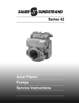
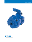
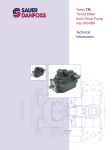
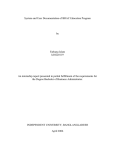
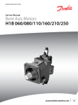
MAKING MODERN LIVING POSSIBLE
Service Manual
Closed Circuit Axial Piston Pumps
Series 42 4T
powersolutions.danfoss.com
Service Manual
Series 42 4T Pumps
Revision history
Table of revisions
2
Date
Changed
Rev
November 2014
Danfoss layout
BA
September 2010
New Back Page
AC
March 2010
Fix Osaka address
AB
July 2008
First edition
AA
11042614 • Rev BA • November 2014
Service Manual
Series 42 4T Pumps
Contents
Introduction
General description
Technical specifications
Pressure measurement
Initial Start-Up Procedure
Fluid and Filter Maintenance
Troubleshooting
Adjustments
Minor repair
Overview..............................................................................................................................................................................................5
Warranty.............................................................................................................................................................................................. 5
General instructions........................................................................................................................................................................ 5
Remove the unit.......................................................................................................................................................................... 5
Keep it clean..................................................................................................................................................................................5
Replace all O-rings and gaskets............................................................................................................................................. 5
Secure the unit............................................................................................................................................................................. 5
Safety precautions............................................................................................................................................................................6
Unintended machine movement..........................................................................................................................................6
Flammable cleaning solvents................................................................................................................................................. 6
Fluid under pressure.................................................................................................................................................................. 6
Personal safety............................................................................................................................................................................. 6
Symbols used in Danfoss literature............................................................................................................................................7
Ordering replacement parts and service................................................................................................................................. 7
Basic design........................................................................................................................................................................................ 8
System diagram................................................................................................................................................................................ 9
System schematic.......................................................................................................................................................................... 10
System specifications................................................................................................................................................................... 11
System parameters........................................................................................................................................................................11
Hydraulic fluid parameters......................................................................................................................................................... 12
Required tools................................................................................................................................................................................. 13
Port locations and pressure gauge installation.................................................................................................................. 13
Ports and pressure gauges......................................................................................................................................................... 13
General...............................................................................................................................................................................................14
Start-up procedure........................................................................................................................................................................ 14
Recommendations........................................................................................................................................................................ 15
Overview........................................................................................................................................................................................... 16
System operating hot...................................................................................................................................................................16
System response is sluggish...................................................................................................................................................... 16
System will not operate in either direction.......................................................................................................................... 17
System will not operate in one direction.............................................................................................................................. 17
Neutral difficult or impossible to find.....................................................................................................................................18
Overview........................................................................................................................................................................................... 19
Displacement limiter adjustment............................................................................................................................................ 19
Conversions................................................................................................................................................................................ 21
Pump neutral adjustment...........................................................................................................................................................21
Control neutral adjustment for MDC and EDC....................................................................................................................22
Standard procedures.................................................................................................................................................................... 24
Remove the pump....................................................................................................................................................................24
Keep it clean............................................................................................................................................................................... 24
Inspect for system contamination......................................................................................................................................24
Replace the O-rings and gaskets.........................................................................................................................................24
Lubricate all moving parts.....................................................................................................................................................24
EDC Spool, linkage, and neutral adjustment screw...........................................................................................................24
Removal........................................................................................................................................................................................24
Installation...................................................................................................................................................................................25
11042614 • Rev BA • November 2014
3
Service Manual
Series 42 4T Pumps
Contents
FNR controls.....................................................................................................................................................................................26
Removal of FNR modules.......................................................................................................................................................27
Installation of FNR modules..................................................................................................................................................27
System Check Relief (SCR) valves)............................................................................................................................................28
Removal........................................................................................................................................................................................28
Inspection....................................................................................................................................................................................29
Replacement.............................................................................................................................................................................. 29
Servo piston covers and NFPH control orifices................................................................................................................... 30
Disassembly................................................................................................................................................................................30
Assembly......................................................................................................................................................................................31
Shafts.................................................................................................................................................................................................. 32
Remove rear shaft.....................................................................................................................................................................33
Remove front shaft (with seal carrier)............................................................................................................................... 33
Remove front shaft (without seal carrier)........................................................................................................................ 33
Inspect shafts............................................................................................................................................................................. 33
Install rear shaft......................................................................................................................................................................... 33
Install front shaft (with seal carrier)....................................................................................................................................33
Install front shaft (without seal carrier).............................................................................................................................33
Port locations and torque chart
Fastener, plug and port locations and gauge installation.............................................................................................. 36
Fastener size and torque chart..................................................................................................................................................36
Plug size and torque chart..........................................................................................................................................................36
4
11042614 • Rev BA • November 2014
Service Manual
Series 42 4T Pumps
Introduction
Overview
This manual includes information for the installation, maintenance, and minor repair of Series 42 axial
piston closed circuit pumps. It includes a description of the unit and its individual components,
troubleshooting information, and minor repair procedures.
Performing minor repairs requires you remove the unit from the vehicle/machine. Thoroughly clean the
unit before beginning maintenance, or repair activities. Since dirt and contamination are the greatest
enemies of any type of hydraulic equipment, follow cleanliness requirements strictly. This is especially
important when changing the system filter and when removing hoses or plumbing.
A worldwide network of Danfoss Global Service Partners (GSPs) is available for major repairs. Danfoss
trains and certifies GSPs on a regular basis. You can locate your nearest GSP using the distributor locator
at www.sauer-danfoss.com. Click on the Sales and Service link.
Warranty
Performing installation, maintenance, and minor repairs according to the procedures in this manual does
not affect your warranty. Major repairs requiring the removal of a unit’s rear cover or front flange voids
the warranty unless done by a Danfoss global service partner.
General instructions
Follow these general procedures when repairing Series 42 variable displacement closed circuit pumps.
Remove the unit
Prior to performing minor repairs, remove the unit from the vehicle/machine. Chock the wheels on the
vehicle or lock the mechanism to inhibit movement. Be aware that hydraulic fluid may be under high
pressure and/or hot. Inspect the outside of the pump and fittings for damage. Cap hoses after removal to
prevent contamination.
Keep it clean
Cleanliness is a primary means of assuring satisfactory pump life, on either new or repaired units. Clean
the outside of the pump thoroughly before disassembly. Take care to avoid contamination of the system
ports. Cleaning parts with a clean solvent wash and air drying is usually adequate.
As with any precision equipment, you must keep all parts free of foreign material and chemicals. Protect
all exposed sealing surfaces and open cavities from damage and foreign material. If left unattended,
cover the pump with a protective layer of plastic.
Replace all O-rings and gaskets
Danfoss recommends replacing all O-rings, gaskets, and seals when servicing. Lightly lubricate all O-rings
with clean petroleum jelly prior to assembly.
Secure the unit
11042614 • Rev BA • November 2014
5
Service Manual
Series 42 4T Pumps
Introduction
For repair, place the unit in a stable position with the shaft pointing downward. It is necessary to secure
the pump while removing and torquing end covers, controls, and valves.
Safety precautions
Always consider safety precautions before beginning a service procedure. Protect yourself and others
from injury. Take the following general precautions whenever servicing a hydraulic system.
Unintended machine movement
W
Warning
Unintended movement of the machine or mechanism may cause injury to the technician or bystanders.
To protect against unintended movement, secure the machine or disable/disconnect the mechanism
while servicing.
Flammable cleaning solvents
W
Warning
Some cleaning solvents are flammable. To avoid possible fire, do not use cleaning solvents in an area
where a source of ignition may be present.
Fluid under pressure
W
Warning
Escaping hydraulic fluid under pressure can have sufficient force to penetrate your skin causing serious
injury and/or infection. This fluid may also be hot enough to cause burns. Use caution when dealing with
hydraulic fluid under pressure. Relieve pressure in the system before removing hoses, fittings, gauges, or
components. Never use your hand or any other body part to check for leaks in a pressurized line. Seek
medical attention immediately if you are cut by hydraulic fluid.
Personal safety
W
Warning
Protect yourself from injury. Use proper safety equipment, including safety glasses, at all times.
6
11042614 • Rev BA • November 2014
Service Manual
Series 42 4T Pumps
Introduction
Symbols used in Danfoss literature
WARNING may result in injury
Tip, helpful suggestion
CAUTION may result in damage to product or
property
Lubricate with hydraulic fluid
Reusable part
Apply grease / petroleum jelly
Non-reusable part, use a new part
Apply locking compound
Non-removable item
Inspect for wear or damage
Option - either part may exist
Clean area or part
Superseded - parts are not interchangeable
Be careful not to scratch or damage
Measurement required
Note correct orientation
Flatness specification
Mark orientation for reinstallation
Parallelism specification
Torque specification
External hex head
Press in - press fit
Internal hex head
Pull out with tool – press fit
Torx head
Cover splines with installation sleeve
O-ring boss port
Pressure measurement/gauge location or
specification
The symbols above appear in the illustrations and text of this manual. They are intended to communicate
helpful information at the point where it is most useful to the reader. In most instances, the appearance
of the symbol itself denotes its meaning. The legend above defines each symbol and explains its purpose.
Ordering replacement parts and service
Danfoss provides a complete repair service for its products. Contact any Danfoss Global Service Partner
for details.
To ensure the best performance, use genuine Danfoss replacement parts. To order parts, contact Danfoss
Extended Customer Service (ECS) at (515) 239-6078, fax (515) 239-6230, or your nearest Global Service
Partner.
Some service parts may be available only in kits, while other parts may be available on an individual basis.
See publication 520L0589 Series 42 PV 41cc Service Parts Manual or 520L0590 Series 42 PV 28cc Service
Parts Manual for listings of available service parts and service kits for Series 42 units.
11042614 • Rev BA • November 2014
7
Service Manual
Series 42 4T Pumps
General description
Basic design
S42 Pumps are advanced hydrostatic units for medium power applications with maximum loads of 415
Bar [6020 psi] (41 cm3) and 350 Bar [5075 psi] (51 cm3). You can combine these pumps with a suitable
Danfoss motor or other products in a system to transfer and control hydraulic power.
The Series 42 variable displacement pump is a compact, high power density unit, using the parallel axial
piston/slipper concept in conjunction with a tiltable swashplate to vary the pump’s displacement..
Reversing the angle of the swashplate reverses the flow of fluid from the pump, and reversing the
direction of rotation of the motor output. Series 42 pumps provide an infinitely variable speed range
between zero and maximum in both forward and reverse.
Series 42 pumps use a cradle swashplate design with a hydraulic servo control cylinder. Control is
provided through a compact servo control system. A variety of servo controls are available. These include
mechanically- or electrically-actuated feedback controls, hydraulic or electric proportional controls, and a
three-position electric control. These controls feature low hysteresis and responsive performance.
28/32/41/51 cm3 cross-sectional view
Swashplate
Slipper
Piston
Cylinderblock
block
Cylinder
Roller bearing
Charge pump
Valve plate
8
11042614 • Rev BA • November 2014
Service Manual
Series 42 4T Pumps
General description
System diagram
Charge Pressure
Control Pressure
System Pressure
Low Loop Pressure
Filter
Charge Pump
Suction
Screen
Suction/Case Drain/
System Return
Bypass Check
Heat Exchanger
Reservoir
Control Handle
Servo Control
Cylinder
Swash Plate
Displacement
Control Spool
Cylinder Block
Assembly
Charge Pressure
Relief Valve
Input
Shaft
Valiable
Displacement
Pump
Brake release
control valve
Loop
Flushing
Valve
Gear box
Motor
Motor displacement
control valve
Loop
Flushing
Valve
Motor
11042614 • Rev BA • November 2014
P106 147E
Charge check/
HPRV valve
Gear box
9
Service Manual
Series 42 4T Pumps
General description
System schematic
4T axial piston pump
M6
L1
L2
Front
Rear
M5
M4
M4
M5
M2
Gearbox
B
M1 A
M6 C
Motor
M1
D
M2
Motor
Gearbox
P107 820E
The illustration above shows a schematic of a 4T axial piston pump. System ports A,C and B,D connect to
the high pressure work lines. Return fluid is received from its inlet port and discharged through the outlet
port. Flow direction is determined by swashplate position. You can read system port pressure through
ports M1 and M2. The pump has two case drains (L1 and L2) to ensure there is lubricating fluid in the
system. This schematic includes a manual displacement control. For other control schematics see the
related control section.
10
11042614 • Rev BA • November 2014
Service Manual
Series 42 4T Pumps
Technical specifications
System specifications
General specifications
Pump type
In-line, axial piston, positive displacement pumps including cradle swashplate
and servo control
Direction of input rotation
Clockwise or counterclockwise
Recommended installation position
Pump installation recommended with control position on the top or side.
Consult Danfoss for non conformance guidelines. The housing must always be
filled with hydraulic fluid.
Other system requirements
Independent braking system, suitable reservoir and heat exchanger.
Hardware features
Pump configuration
Integrated Tandem Pump
Displacement cm3/rev [in3/rev]
41 [2.50] x 2
Weight kgf [lbf]
MDC: 76 [168]
51 [3.11] x 2
NFPH: 72 [158]
Mass moment of inertia
kg•m2 [lbf•ft2]
0.0072 [0.0054]
0.0076 [0.0056]
Type of front mounting flange
(SAE flange size per SAE J744)
2 Bolt SAE C, (4 additional bolt holes available)
Port connections
SAE-twin ports, radial, opposite side ports
System pressure regulation
bar [psi]
210-415 [3045-6020]
Displacement limiters
Option
Input shaft options
Splined
Auxiliary mounting pad
(SAE pad per SAE J744)
SAE A (9 tooth, 11 tooth, 13 tooth)
SAE B (13 tooth)
Control options
MDC, NFPH, EDC, FNR
Loop flushing
NONE
210-325 [3045-4715]
System parameters
Case pressure
Continuous pressure bar [psi]
3.4 [50]
Maximum pressure (cold start) bar [psi]
10.3 [150]
Pressure limits
Displacement cm3/rev
41
51
Rated pressure bar [psi]
350 [5075]
325 [4713]
Maximum pressure bar [psi]
415 [6017]
350 [5075]
Speed limits
Displacement cm3/rev
41
Minimum speed min-1 (rpm)
500
Rated speed at maximum displacement min-1 (rpm)
3200
11042614 • Rev BA • November 2014
51
2900
11
Service Manual
Series 42 4T Pumps
Technical specifications
Speed limits (continued)
Maximum speed at maximum displacement min-1 (rpm)
3450
3400
41
51
none
Charge pump displacement and setting pressure
Charge pump
Internal cm3/rev [in3/rev]
—
none
Charge relief valve
settings bar [psi]
Standard
20 [290]
Optional
14-24 [203-340]
Theoretical flow
Displacement cm3/rev
41
51
Theoretical flow at rated speed l/min [US gal/min]
131 [34.6]
148 [39.1]
Check / high pressure relief valve
Options
No relief valve / check only
Relief valve / check
Settings bar [psi]
-
210-415 [3045-6020] or by setting available
210, 250, 280, 300, 325, 345, 360, 385, 415
Hydraulic fluid parameters
Fluid temperature range
Minimum
-40 °C [-40 °F]
Intermittent, cold start
Maximum continuous
104 °C [220 °F]
-
Maximum
115 °C [240 °F]
Intermittent
Fluid cleanliness level
Required fluid cleanliness level
ISO 4406 Class 22/18/13
Fluid viscosity
Minimum
7.0 mm2/s (cSt)
Intermittent
Recommended operating range
12-60 mm2/s (cSt)
-
Maximum
1600 mm2/s (cSt)
Intermittent, cold start
12
11042614 • Rev BA • November 2014
Series 42 4T Pumps
Service Manual
Pressure measurement
Required tools
You can perform the service procedures in this manual using common mechanic’s hand-tools. Calibrate
gauges frequently to ensure accuracy. Use snubbers to protect pressure gauges.
Port locations and pressure gauge installation
On pumps with non-feedback controls, the positions of the case drains may vary.
Ports and pressure gauges
Proper service and diagnosis may require pressure measurement at various points in the hydraulic circuit.
The Series 42 pump has several locations at which to take these measurements. The following illustration
shows the locations of the various gauge ports. The table shows the recommended gauge size and the
fitting size for each port.
Gauge ports
Gauge port
Pressure measured
Recommended gauge size
O-ring boss
28 cc
41 / 51 cc
M1 & M2
System pressure for ports A and B
600 bar [8700 psi]
9/16/-18
9/16/-18
M4 & M5
Servo pressure
60 bar [870 psi]
9/16-18
9/16-18
L1 & L2
Case pressure
35 bar [510 psi]
1-1/16-12
1-5/16-12
4T gauge ports
M4
M2
M5
B system pressure
(D on other side)
M1
A system pressure
(C on other side)
L2 (L1 on other side)
P107 818E
11042614 • Rev BA • November 2014
13
Service Manual
Series 42 4T Pumps
Initial Start-Up Procedure
General
Follow this procedure when starting-up a new Series 42 installation or when restarting an installation in
which the pump has been removed.
W
Warning
Unintended movement of the machine or mechanism may cause injury to the technician or bystanders.
To protect against unintended movement, secure the machine or disable/disconnect the mechanism
while servicing.
Prior to installing the pump, inspect for damage incurred during shipping. Make certain all system
components (reservoir, hoses, valves, fittings, heat exchanger, etc.) are clean prior to filling with fluid.
Start-up procedure
1. Connect the pump to the prime mover. Ensure that pump shaft is properly aligned with the shaft of
the prime mover.
C
Caution
Incorrect shaft alignment may result in damage to drive shaft, bearings, or seal which can cause
external oil leakage.
2. Fill the reservoir with recommended hydraulic fluid. Always filter fluid through a 10 micron absolute
filter pouring into the reservoir. Never reuse hydraulic fluid.
3. Fill the main pump housing with clean hydraulic fluid. Pour filtered oil directly into the upper most
case drain port.
4. Fill the inlet line leading from the pump to the reservoir. Check the inlet line for properly tightened
fittings and be certain it is free of restrictions and air leaks.
5. To ensure the pump stays filled with oil, install the case drain line in the upper most case drain port.
6. Install a gauge at port M2 to monitor system pressure during start up.
Follow recommendations in the vehicle/machine operator’s manual for prime mover start up
procedures.
7. While watching the pressure gauge at M2, jog the prime mover or run at the lowest possible speed
until system pressure builds to normal levels (minimum 11 bar [160 psi]). Once system pressure is
established, increase to full operating speed. If the pump does not maintain system pressure, shut
down the prime mover, determine cause, and take corrective action. Refer to Troubleshooting on
page 16.
8. Operate the hydraulic system for at least fifteen minutes under light load conditions.
9. Check and adjust control settings as necessary after installation. Refer to Adjustments on page 19.
10. Shut down the prime mover and remove the pressure gauge. Replace plug at port M2.
11. Check the fluid level in the reservoir; add clean filtered fluid if necessary.
The pump is now ready for operation.
14
11042614 • Rev BA • November 2014
Service Manual
Series 42 4T Pumps
Fluid and Filter Maintenance
Recommendations
To ensure optimum life of Series 42 products, perform regular maintenance of the fluid and filter.
Contaminated fluid is the main cause of unit failure. Take care to maintain fluid cleanliness when
servicing.
Check the reservoir daily for proper fluid level, the presence of water, and rancid fluid odor. Water in the
fluid may be noted by a cloudy or milky appearance or free water in the bottom of the reservoir. Rancid
odor indicates the fluid has been exposed to excessive heat. Change the fluid immediately if these
conditions occur. Correct the problem immediately.
Change the fluid and filter per the vehicle/machine manufacturer’s recommendations or at these
intervals:
Change the fluid more frequently if it becomes contaminated with foreign matter (dirt, water, grease,
etc.) or if the fluid is subjected to temperature levels greater that the recommended maximum.
Dispose of used hydraulic fluid properly. Never reuse hydraulic fluid.
Change filters whenever the fluid is changed or when the filter indicator shows that it is necessary to
change the filter. Replace all fluid lost during filter change.
Fluid and filter change intervals
Sealed reservoir
2000 hours
Breather reservoir
500 hours
11042614 • Rev BA • November 2014
15
Service Manual
Series 42 4T Pumps
Troubleshooting
Overview
This section provides general steps to follow if you observe certain undesirable system conditions. Some
of the items are system specific. Always observe the safety precautions listed in the introduction of this
manual. If standard troubleshooting procedures do not remedy the problem, contact a Danfoss Global
Service Partner.
System operating hot
Item
Description
Action
Oil level in reservoir
Insufficient hydraulic fluid will not meet the
cooling demands of system.
Fill the reservoir to the proper level with clean
hydraulic oil.
Heat exchanger (if equipped)
The heat exchanger is not sufficiently cooling the
system.
Check the air flow and input air temperature for
the heat exchanger. Clean, repair, or replace the
heat exchanger as necessary.
Bypass valve
A partially activated bypass valve may result in heat Verify that the bypass valve is fully closed and that
generation within the system.
the valve is seating properly. Repair or replace it as
necessary.
SCR (System Check / Relief) Valves
A partially activated SCR valve or SCR valves with
relief settings too low may result in heat
generation within the system.
Verify that the SCR valve is seating properly and is
at the correct relief setting. Repair or replace it as
necessary.
Oil filters
Clogged oil filters may result in an insufficient
supply of cool oil to the system.
Inspect the oil filters and verify that they are still
operable. Replace them if necessary.
Machine load
Excessive loads or extreme duty cycles could result
in the pump and/ or motor operating at speeds
and pressures beyond system design limitations.
Verify that the machine is operating within the
parameters for which it was designed. If necessary,
reduce the load on the machine.
Item
Description
Action
Reservoir oil level
There is an insufficient amount of hydraulic fluid,
resulting in an inadequate supply for the system
loop.
Fill the reservoir to the proper level with clean
hydraulic fluid.
Input control signal
(linkage, current, or pressure)
The pump is receiving a faulty control signal: (MDC Verify that the input signal is correct and identical
- binding or broken linkage; EDC - faulty or
in both directions.
inadequate electrical signal; HDC - blocked or
incorrectly orificed control lines).
Pump control
A damaged pump control or control spool will not
correctly transmit the control input signal to the
pump.
Verify that the pump’s control is operating properly
and that the control spool is not damaged or worn
and moves freely within its bore. Clean, repair, or
replace it as necessary.
Bypass valve
A partially activated bypass valve will cause cross
port leakage.
Verify that the bypass valve is closed and that the
valve is seating properly. Clean, repair, or replace it
as necessary.
SCR (system check / relief) valves
One or both of the SCR valves may be binding
within their bores.
Verify that the SCR valves operate freely. Repair or
replace them as necessary.
Charge pressure (in neutral)
Low charge pressure resulting from a damaged
charge pump or low charge pressure relief valve
setting. Charge pressure may be insufficient to
recharge the system loop.
Inspect the charge pump for damage and verify
the charge pressure relief valve setting. Repair or
replace it as necessary.
Charge pressure (in stroke)
There is low charge pressure resulting from internal Repair or replace the component or components
leakage within the system.
within the system causing the internal leakage.
System response is sluggish
16
11042614 • Rev BA • November 2014
Service Manual
Series 42 4T Pumps
Troubleshooting
Item
Description
Action
Servo pressure
There is insufficient pressure differential across the
servo piston.
Check servo pressures at port M4 and M5 to verify
sufficient pressure delta. Verify that the servo
supply and drain paths are unobstructed and that
any orifices are of the correct size and free of
debris. Clean, repair, or replace as necessary.
Charge pump
The charge pump has been damaged or installed
with the incorrect rotational orientation.
Verify that the charge pump is in good working
order and that it is correctly installed. Repair or
replace it as necessary.
System will not operate in either direction
Item
Description
Action
Oil level in reservoir
There is an insufficient amount of hydraulic fluid,
resulting in an inadequate supply for the system
loop.
Fill the reservoir to the proper level with clean
hydraulic oil.
Input control signal
(linkage, current, or pressure)
The pump is receiving a faulty control signal: (MDC Verify that the input signal is correct and identical
- binding or broken linkage; EDC - faulty or
in both directions. Adjust, clean, repair, or replace
inadequate electrical signal; HDC - blocked or
the input device as necessary.
incorrectly orificed control lines).
Oil filters
Clogged oil filters may result in an insufficient
supply of oil to the system.
Inspect the oil filters and verify that they are still
serviceable. Replace them as necessary.
Bypass valve
A partially activated bypass valve may result in a
cross port leakage.
Verify that the bypass valves are closed and that
the valves are seating properly. Clean, repair, or
replace them as necessary.
Charge pressure
(in neutral)
Charge pressure may be insufficient to recharge
the system loop.
Inspect the charge pump for damage and verify
that the charge pressure relief valve is at the proper
setting. Repair or replace it as necessary.
Charge pressure
(in stroke)
Low charge pressure resulting from internal
leakage within the system.
Repair or replace the component or components
within the system causing the internal leakage.
Servo pressure
There is an insufficient pressure differential across
the servo piston.
Check servo pressures to verify sufficient pressure
delta. Verify that the servo supply and drain paths
are unobstructed and that any orifices are of the
correct size and free of debris. Clean, repair, or
replace them as necessary.
Charge pump
The charge pump is damaged or has been installed Verify that the charge pump is in good working
with the incorrect rotational orientation.
order and that it is correctly installed. Repair or
replace it as necessary.
SCR (system check / relief) valves
The SCR valves are malfunctioning or improperly
set.
Verify that the SCR valves are operating and
properly set. Repair or replace them as necessary.
Displacement limiters
The displacement limiters may be improperly
adjusted such that the servo piston is prevented
from moving in one direction.
Verify that the displacement limiters are adjusted
to the proper setting.
Item
Description
Action
Input control signal (linkage, current, or
pressure)
The pump is receiving a faulty control signal: (MDC Verify that the input signal is correct and identical
- binding or broken linkage; EDC - faulty or
in both directions. Adjust, clean, repair, or replace
inadequate electrical signal; HDC - blocked or
the control module as necessary.
incorrectly orificed control lines).
SCR (System Check/Relief) valves
The SCR valves are malfunctioning or improperly
set.
System will not operate in one direction
11042614 • Rev BA • November 2014
Verify that the SCR valves are operating properly.
Repair or replace them as necessary.
17
Service Manual
Series 42 4T Pumps
Troubleshooting
Item
Description
Action
Pump control
A damaged or biased pump control may be
sending a signal commanding the pump to stroke
only in one direction.
Verify that the pump’s control is functioning
properly. Repair or replace it as necessary.
Servo pressure
The drain or supply path to one side of the servo
piston may be blocked.
Verify that the servo supply and drain paths are
unobstructed and that any orifices are of the
correct size and free of debris. Clean or repair them
as necessary.
Displacement limiters (if equipped)
The displacement limiters may be improperly
adjusted such that the servo piston is prevented
from moving in one direction.
Verify that the displacement limiters are adjusted
properly.
Item
Description
Action
Input control signal (linkage, current, or
pressure)
The pump is receiving a faulty control signal: (MDC Verify that the input signal is correct and identical
- binding or broken linkage; EDC - faulty or
in both directions. Adjust, clean, repair, or replace
inadequate electrical signal; HDC - blocked or
control module as necessary.
incorrectly orificed control lines).
System pressure
With no input signal to the control, a pressure delta Readjust pump neutral setting. Refer to Pump
may exist between the two sides of the working
neutral adjustment on page 21.
loop.
Servo pressure
With no input signal to the control, a pressure delta Readjust the control neutral setting. Refer to
may exist across the servo piston.
Control neutral adjustment for MDC and EDC on
page 22.
PCP pressure (EDCs only)
With no input signal to the control, a pressure
difference may exist across the control spool.
Neutral difficult or impossible to find
18
11042614 • Rev BA • November 2014
Replace the EDC.
Service Manual
Series 42 4T Pumps
Adjustments
Overview
This section offers instruction on how to perform adjustments to the Series 42 pump. Read through the
entire procedure before beginning any service activity. Refer to Port locations and pressure gauge
installation on page 13 for location of gauge ports and suggested gauge size.
Displacement limiter adjustment
You may adjust displacement limiters to achieve a desired maximum flow rate. For Series 42 pumps,
displacement limiters are available on one or both sides of the servo piston.
Accurate adjustment of the displacement limiters requires the use of a test stand capable of measuring
system flow output from both the A and B output ports.
1. Mount the pump onto the test stand.
2. Loosen the displacement limiter seal lock nut (L025), but do not remove it.
3. Start the prime mover and place the pump into full stroke in one direction. Note the system output
flow from either the A or B system port.
4. Adjust the displacement limiter adjustment screw (L020) until the desired output flow is reached.
Turning the displacement limiter adjustment screw clockwise decreases the maximum output flow
setting. Turning the displacement limiter adjustment screw counter clockwise increases the
maximum output flow setting.
W
Warning
WARNING
The seal nut lock nut must be retorqued after every adjustment and the limiter screw must have full
thread engagement in the servo piston cover to prevent unexpected changes in operating conditions
and to prevent external leakage during unit operation.
The pump achieves maximum flow when the displacement limiter does not contact the servo piston
while the unit is in full stroke. One full turn of the displacement limiter adjustment screw results in
approximate flow output changes per the table.
5. Once you achieve the proper output flow, torque the displacement limiter seal lock nut (L025) to
20-26 N•m [15-19 lbf•ft] while holding the position of the adjustment screw (L020).
11042614 • Rev BA • November 2014
19
Service Manual
Series 42 4T Pumps
Adjustments
6. If required, repeat this procedure using the opposite displacement limiter to set the output flow in
the other direction.
Displacement limiters
L020
Displacement
limiter
4 mm
L025
Displacement
limiter seal
lock nut
13 mm
20-26 N•m
[15-19 lbf•ft]
L001
Servo
piston
cover
RIGHT SIDE VIEW (M4)
M020
Displacement
limiter
4 mm
M025
Displacement
limiter seal
lock nut
13 mm
20-26 N•m
[15-19 lbf•ft]
M001
Servo
piston
cover
LEFT SIDE VIEW (M5)
Displacement limiter adjustment
20
Size
Displacement change per turn
41 cm3
5.0 cm3/rev [.31 in3/rev]
11042614 • Rev BA • November 2014
Service Manual
Series 42 4T Pumps
Adjustments
Conversions
Changes to the displacement limiter settings are conversions to the pump. Change the nomenclature on
the specification tag to reflect the alterations of the unit. Refer to 520L0637 Series 42 Technical
Information Manual, Model Code Supplement, or contact your Danfoss representative for the appropriate
nomenclature.
Pump neutral adjustment
Zero output flow from the pump defines the neutral condition. To attain zero output flow, the pump
must achieve both mechanical neutral and control neutral conditions. Mechanical neutral is the condition
when the swashplate is at zero angle without any signal input from the control. Set mechanical neutral
prior to setting control neutral.
W
Warning
To prevent injury, disable the machine: raise wheels off the ground or disconnect the mechanism..
1. Disable the control input to the pump by equalizing the pressures on both ends of the pump servo
piston. To accomplish this, connect an SAE‑06 hose between servo gauge ports, M4 and M5.
2. Install pressure gauges in gauge ports M1 and M2 to measure system pressure.
3. Start the prime mover and run at normal operating speed.
4. Loosen the pump neutral adjustment seal lock nut (T060) in the center of the servo cover on the right
side of the pump.
5. Turn the adjustment screw (T015) clockwise until one of the gauges registers an increase in system
pressure. Mark the position of the adjustment screw. Turn the screw counterclockwise until the other
gauge registers an increase in system pressure. Mark the position of the adjustment screw. Turn the
adjustment screw clockwise to a position halfway between the marks. The system pressure gauges
should indicate equal pressures.
6. While holding the adjustment screw in position, torque the seal lock nut (T060). Torque to 31-50 N•m
[23-37 lbf•ft].
7. Stop the prime mover and remove the hose between gauge ports M4 and M5. Remove the pressure
gauges in gauge ports M1 and M2. Reinstall the plugs in the gauge ports.
8. Proceed to the control neutral adjustment section on the next page.
Pump neutral adjustment screw
T060
Pump mechanical
neutral adjustment
seal lock nut
See table
See table
T015
Pump neutral
adjustment screw
See table
See table
E100002E
MDC Shown
11042614 • Rev BA • November 2014
21
Service Manual
Series 42 4T Pumps
Adjustments
Neutral adjustment gauge port readings
M1 / M2
M1 / M2
M1 / M2
P101259
Frame size cm3
41/51
Control
MDC/EDC
NFP
Lock nut mm
17
17
Servo adjust screw mm [in]
7
7
Lock nut torque N•m [lbf•ft ]
31-50 [23-37]
31-50 [23-37]
Control neutral adjustment for MDC and EDC
Control neutral adjustment aligns the pump swashplate and the control spool so that a zero angle
control setting provides a zero degree swashplate setting. Perform this adjustment whenever you adjust
or move any part of the control or swashplate mechanism or after you adjust the pump neutral setting.
W
Warning
The following procedure requires the vehicle/machine to be disabled (wheels raised off the ground, work
function disconnected, etc.) while performing the procedure in order to prevent injury to the technician
and bystanders.
1. Disconnect the external control linkage (for MDC) or control signal input (for EDC) from the pump.
2. Install pressure gauges in the servo gauge ports M4 and M5 to measure pressure on the pump servo
piston.
3. Start the prime mover and run at normal operating speed.
4. Loosen the control neutral adjustment seal lock nut (D015).
5. Turn the adjustment screw (D014) clockwise until one of the gauges registers an increase in pressure
on the servo piston. Mark the position of the adjustment screw. Turn the screw counterclockwise until
the other gauge registers an increase in pressure on the servo piston. Mark the position of the
adjustment screw. Turn the adjustment screw clockwise so that it is midway between the marks.
Adjustment screw movement produces constant change for both directions, so both the pressure
gauges should indicate nearly equal pressures.
6. While holding the adjustment screw (D014) in position, torque the seal lock nut (D015) to 31-50 N•m
[23-37 lbf•ft].
7. Stop the prime mover and remove the pressure gauges. Remove the plugs in the gauge ports.
22
11042614 • Rev BA • November 2014
Service Manual
Series 42 4T Pumps
Adjustments
8. Connect the external control linkage (for MDC) or control signal input (for EDC) to the pump.
Reconnect the work function.
Control neutral adjustment screw
D014
MDC / EDC neutral
adjustment screw
5 mm
D015
MDC / EDC neutral
adjustment seal lock nut
17 mm
31-50 N•m [23-37 lbf•ft]
E100003E
EDC Shown
Equalization of pressure gauges using pump neutral adjustment screw
M3 / M4
M3 / M4
M3 / M4
P101 270E
11042614 • Rev BA • November 2014
23
Service Manual
Series 42 4T Pumps
Minor repair
Standard procedures
Remove the pump
Prior to performing certain minor repairs on the Series 42 pump, it may be necessary to remove the
pump from the machine. Chock wheels of vehicle to prohibit movement. Be aware that hydraulic fluid
may be under high pressure and may be hot. Inspect the outside of the pump and fittings for damage.
Keep it clean
Cleanliness is a primary means of assuring satisfactory pump life, on either new or repaired units. Clean
the outside of the pump thoroughly before disassembly. Take care to avoid contamination of the system
ports. Clean parts using a clean solvent wash and air dry.
As with any precision equipment, keep all parts free of foreign materials and chemicals. Protect all
exposed sealing surfaces and open cavities from damage and foreign material. If left unattended, cover
the pump with a protective layer of plastic.
Inspect for system contamination
Inspect the pump for system contamination. If you find contamination, fully disassemble, clean, and
inspect all components of the pump. Pump warranty will be voided unless disassembly and rebuild are
performed by a Danfoss Global Service Provider.
Replace the O-rings and gaskets
Danfoss recommends you replace all O-rings and gaskets. Lightly lubricate O-rings with clean petroleum
jelly prior to assembly.
Lubricate all moving parts
During reassembly, coat all moving parts with a film of clean hydraulic oil. This will help to lubricate these
parts during start-up. For fluid quality requirements, refer to bulletin 520L0463 Hydraulic Fluids and
Lubricants, Technical Information.
EDC Spool, linkage, and neutral adjustment screw
It may be necessary to remove the control spool, control linkage, and control neutral adjustment screw
for cleaning and to change the O-rings or the seal lock nut.
Removal
1. Clean the external surface of the pump.
2. Use a T30 Torx to remove the screws (D002). Remove control modules from pump. Remove and
discard gaskets (E011).
Note control linkage assemblies, and the way the summing links engage the control spool flats.
3. Remove the summing links (D011) by sliding them off the feedback link. Using a 4mm internal hex
wrench, remove the summing link pivot pin (D010). Slide the feedback link (D012) towards the servo
piston to disengage the neutral adjustment link (D013). Remove all linkages.
4. Remove plugs (D032). Note the orientation of the control spools (D90) and which side of the pump
the springs (D91) are located. Remove control spools, washers and springs.
5. Remove the seal nuts (D015) and neutral adjustment screws (D014). Note position of adjustment
screws for reassembly.
24
11042614 • Rev BA • November 2014
Service Manual
Series 42 4T Pumps
Minor repair
Installation
1. Install adjustment screws (D014) to position previously noted. Install lock nuts (D015). Do not tighten
the nuts. After pump is installed on machine, refer to Control neutral adjustment for MDC and EDC on
page 22 for control neutral adjustment procedure.
2. Lubricate and install spools (D90), washers (D92) and springs (D91), noting proper orientation. Install
the two side bore plugs and torque to 65 N•m [48 lbf•ft].
3. Combine the center pin of the feedback links (D012) with the mating bore of the neutral adjustment
links (D013). Insert the end of the feedback links into the servo piston slots. Mate the neutral
adjustment links with the control neutral adjustment screws (D014). Insert the linkage pivot screws
(D010) and torque to 12 N•m [9 lbf•ft]. Install the summing links (D011). It may be necessary to rotate
the control spools so that the summing link forks engage the flats on the control spools.
4. Install new gaskets (E011). Install controls.
11042614 • Rev BA • November 2014
25
Service Manual
Series 42 4T Pumps
Minor repair
5. Install screws (D002). Torque to 16 Nm [12 lbf•ft].
MDC / EDC spool and linkage
T30
D002
16 Nm
[12 lbf•ft]
T30
D002
16 Nm
[12 lbf•ft]
FD01
RD01
E011
E011
D011
D011
D012
D012
D010
4 mm
D013
D010
4 mm
D015
17 mm
D014
5 mm
D032A
D032
D091 7/8 inch
65 Nm
D092
[48 lbf•ft]
D090
D013
F035A
F035
6 mm
65 Nm
[48 lbf•ft]
F035A
F035
6 mm
65 Nm
[48 lbf•ft]
D090
D092
D091
D132A
D132
65 Nm
7/8 inch
[48 lbf•ft]
D015
17 mm
D014
5 mm
P107 778E
FNR controls
FNR controls are non-feedback type controls. The FNR controls consist of external, solenoid-actuated
spool valves mounted on the pump housing.
It may be necessary to remove the FNR controls to clean the ports and replace the O-rings, however the
controls themselves are not serviceable.
26
11042614 • Rev BA • November 2014
Service Manual
Series 42 4T Pumps
Minor repair
Removal of FNR modules
1. Clean the pump and control housings.
2. Use a 4 mm internal hex to remove screws (D081). Remove the control modules from the pump
housing.
3. Remove and discard the O-rings (FD01A) from the control ports. Examine the ports for cleanliness.
4. Use a 4 mm internal hex to remove screws (D180). Remove plates (D043) and (D143).
5. Remove and discard gaskets (D044).
6. If necessary, remove plugs (D032) and (F035). Remove and discard O-rings (D035A) and (D032A).
The spools are solid; other than plugging the bores, they do not provide any function.
7. Unless leaking fluid, adjusting screws (D014) and lock nuts (D015) do not need to be removed.
Other than plugging the bores, adjusting screws do not provide any function.
Installation of FNR modules
1. If previously removed, install spools (D090). Lubricate and install new O-rings (D032A), and (F035A).
Install plugs (D032) and (F035). Torque to 65 Nm [48 lbf•ft].
2. If previously removed, install adjusting screws (D014) and locknuts (D015). Torque locknuts to 40 Nm
[30 lbf•ft].
3. Clean the sealing surfaces on the controls and housing.
4. Install gaskets (D044). Install plates (D043) and (D143). Use a 4 mm internal hex to install screws
(D180). Torque to 16 Nm [12 lbf•ft].
5. Using petroleum jelly, lubricate and install O-rings (FD01A) to bottom of controls.
11042614 • Rev BA • November 2014
27
Service Manual
Series 42 4T Pumps
Minor repair
6. Install control modules. Use a 4 mm internal hex, install screws (D081). Torque to 16 N•m [12 lbf•ft].
FNR Minor Repair
D081
4 mm
16 N•m
[12 lbf•ft]
FD01
D081
4 mm
16 N•m
[12 lbf•ft]
RD01
FD01A
FD01A
D180
4 mm
16 N•m
[12 lbf•ft]
D043
D180
4 mm
16 N•m
[12 lbf•ft]
D043
D044
D044
D014
5 mm
40 N•m
[30 lbf•ft]
D015
17 mm
D090
F035A
D032A
D032
6 mm
65 N•m
[48 lbf•ft]
F035
6 mm
65 N•m
[48 lbf•ft]
F035A
F035
6 mm
65 N•m
[48 lbf•ft]
D032A
D032
6 mm
65 N•m
[48 lbf•ft]
D090
D014
6 mm
D015
17 mm
40 N•m
[30 lbf•ft]
P107 779E
System Check Relief (SCR) valves)
The System Check Relief valve assembly performs the charge check, high pressure relief, and loop bypass
functions. You may remove this assembly for cleaning and replacement of O-rings.
Removal
1. Using a 1 inch wrench or an 8 mm internal hex, remove the valve seat plugs (K001) from the pump
housing. Remove and discard the O-rings and backup rings (K008, K009, and K010).
28
11042614 • Rev BA • November 2014
Service Manual
Series 42 4T Pumps
Minor repair
2. Remove the SCR valve assemblies (H005/J005).
If SCR valve does not have a bypass plunger, skip steps 3 and 4.
3. Use a snap ring pliers to remove retaining ring (K005).
4. Remove bypass plunger (K002) and O-rings (K006). Discard O-rings.
Inspection
Inspect the valves and mating seats in the valve seat plugs (K001) for damage or foreign material.
The SCR valves (H005/J005) are not serviceable; replace as a complete unit.
Replacement
If SCR valve does not have a bypass plunger, skip steps 6 and 7.
1. Lubricate and install O-rings (K006) onto bypass plunger.
2. Install bypass plunger (K002). Install snap ring (K005).
3. Install new outer O-ring (K008), backup ring (K009), and inner O-ring (K010) on each valve seat plug.
4. Verify that the conical springs are properly retained on the check poppets/relief valves (H005/J005).
Install the check poppet/relief valve assemblies into the pump housing. Ensure that the valve
assembly moves freely in its bore.
11042614 • Rev BA • November 2014
29
Service Manual
Series 42 4T Pumps
Minor repair
5. Using a 1 inch wrench or an 8 mm internal hex, install the valve seat plugs or valve seat/bypass plugs
into the pump housing and torque to 82 N•m [60 lbf•ft].
System check relief valve components
82 N•m
K001
[60 lbf•ft] 1 inch
K005
K002
K006
K008
K009 K008
K010
K009
K010
K001
8 mm
82 N•m
[60 lbf•ft]
J015
H003
H015
J005
82 N•m
[60 lbf•ft]
H003
K001
1 inch
K005
H005
K010
K009
K008
K001
K006
8 mm
K002
82 N•m
[60 lbf•ft]
K010
K009
K008
P107 780E
Servo piston covers and NFPH control orifices
You can remove the servo piston covers to replace the gasket or to clean or replace the NFPH control
orifices.
Disassembly
1. Use a 13 mm or 17 mm wrench to remove locknuts (T060).
30
11042614 • Rev BA • November 2014
Service Manual
Series 42 4T Pumps
Minor repair
2. Using a T-30 Torx, remove the servo cover screws (L005/M005).
W
Warning
Unintended vehicle movement hazard: When you remove the right side servo piston cover, adjust
neutral and control neutral after reinstalling the pump. Refer to Pump neutral adjustment on page 21
and Control neutral adjustment for MDC and EDC on page 22.
3. Remove servo piston covers (L001/M001).
To remove the right side servo cover turn the neutral adjusting screws (T015)clockwise until cover
can be turned off without interference from housing.
4. Remove gaskets (F009). Clean gasket sealing surfaces.
5. If so equipped, NFPH orifice plugs (E051 and E052) are located beneath the servo covers. If necessary,
use a 3 mm internal hex to remove the orifices and clean them.
Assembly
1. If previously removed, replace the NFPH orifice plugs (E051, E052). Torque to 2-4 Nm [1.5-3 lbf•ft].
2. Install new gaskets (L002/M002).
3. On the right side, thread the servo piston cover (L001) onto the neutral adjustment screw. Then, while
holding the cover, turn the neutral adjustment screw (T015) counter-clockwise to run the cover down
the screw threads.
4. Using a T30 Torx driver, install the servo piston cover screws (L005/M005). Torque to 16 N•m [12 lbf•ft]
in the pattern shown.
Bolt torque pattern
TORQUE BOLTS IN ORDER INDICATED
2
3
4
1
5
Torque this
screw first
and last
P101585
5. Use an 8 mm wrench to secure neutral adjusting screw. Install a new seal lock nut (T060) onto the
neutral adjustment screw (T015). Do not torque at this time.
6. Perform pump neutral adjustment and control neutral adjustment procedures. Refer to Control
neutral adjustment for MDC and EDC on page 22.
Removal of the servo covers may change the position of optional displacement limiters; readjust if
necessary (see Displacement limiter adjustment on page 19).
Wrench size for locknut (T060) and neutral adjust screw (T015)
Frame size cm3
41/51
Control
MDC/EDC
NFPE/NFPH
Lock nut (T060)
17 mm
17 mm
Neutral adjust screw (T015)
7 mm
7 mm
11042614 • Rev BA • November 2014
31
Service Manual
Series 42 4T Pumps
Minor repair
Servo piston covers
F009
L001
M001
F009
16 Nm [12 lbf•ft]
M005
T30
16 Nm [12 lbf•ft]
T060
13 mm
T30
L005
T060
13 mm
L005
T30
16 Nm [12 lbf•ft]
L001
T015
Neutral adjust screw
F009
F009
16 Nm [12 lbf•ft]
T30
M005
P107 781E
M001
Removing NFPH orifirces - single pumps shown
E051
NFPH orifice
3 mm
2-4 N•m
[1.5-3 lbf•ft]
E052
NFPH orifice
3 mm
2-4 N•m
[1.5-3 lbf•ft]
E100026E
Shafts
Orient housing so shaft to be replaced is on top. Do not move the pump until the shaft has been replace.
32
11042614 • Rev BA • November 2014
Service Manual
Series 42 4T Pumps
Minor repair
Remove rear shaft
1. Remove retaining ring (C012). Remove bearing (C009).
2. Pull shaft (C006) from housing. If necessary, use a snap ring pliers to pull shaft.
C
Caution
Do not damage machined surfaces of pump when removing shaft.
Remove front shaft (with seal carrier)
1. Remove retaining ring (F096). Remove shaft seal carrier (C020).
2. Remove shaft seal carrier (C020). Remove and discard O-ring (C017).
3. Press seal out of carrier and discard it.
4.
Remove shaft with bearing from housing.
5. If replacing bearing, use a snap-ring pliers to remove retaining ring (C002 or C010). Remove roller
bearing (C003 or C008).
Remove front shaft (without seal carrier)
1.
Remove shaft with bearing from housing.
2. If replacing bearing, use a snap-ring pliers to remove retaining ring ( C010). Remove roller bearing
(C008).
Inspect shafts
Check to see that the shaft and its splines are straight and free of damage or heavy wear. Inspect the
shaft sealing surface. Replace the shaft if a groove exists at the sealing land. Clean the sealing area
with a nonabrasive material.
Install rear shaft
1. Lubricate and install bearing (C009) onto shaft (U001).
2.
Install shaft with bearing into housing.
C
Install retaining ring (C012).
Caution
Do not damage machined surfaces of pump when removing shaft.
Install front shaft (with seal carrier)
1. Lubricate and install bearing (C003) onto shaft.
2.
Use a snap ring pliers to install retaining ring (C002). Install shaft with bearing into housing.
3. Lubricate and install seal (C018) into seal carrier (C020). Lubricate and install O-ring (C017).
4. Install seal carrier into housing. Install retaining ring (F096).
Install front shaft (without seal carrier)
1. Lubricate and install roller bearing (C008).
11042614 • Rev BA • November 2014
33
Service Manual
Series 42 4T Pumps
Minor repair
2.
Install shaft with bearing into housing. Install retaining ring (C010).
Replace shafts
Rear shaft
Front shafts
F096
C012
C020
C010
C009
C017
C008
C018
C002
C003
C006
C005
C001
P107 782E
34
11042614 • Rev BA • November 2014
Service Manual
Series 42 4T Pumps
Minor repair
Seal carrier assembly
C017
C018
C020
Seal carrier shown
with the inside
facing up
11042614 • Rev BA • November 2014
Press seal to bottom of carrier
P107 783E
35
Service Manual
Series 42 4T Pumps
Port locations and torque chart
Fastener, plug and port locations and gauge installation
The following table shows the fastener, plug and port locations and gauge sizes needed.
Port information
Port identifier
Port size
Wrench size
Pressure obtained
Gauge size, bar [psi]
L1, L2
1 5/16-12 UNF-2B
15 mm internal hex
Case drain
10 [100]
M1, M2
9/16-18 UNF
7 mm internal hex
System pressure
600 [10,000]
M4, M5
9/16-18 UNF
7 mm internal hex
Servo pressure
50 [1000]
System ports
Port identifier
110 Split flange boss, thread M12 x 1.75
A
1 1/16-12 UN-2B
B
1 1/16-12 UN-2B
Fastener size and torque chart
Item
Fastener
Wrench size
Torque
D081
EDC/MDC kit screws (not shown)
1/2 inch
16 N•m [12 lbf•ft]
B002
Side cover screws
13 mm
16 N•m [12 lbf•ft]
D002
Control cover screws
T30 Torx
16 N•m [12 lbf•ft]
L020
Displacement limiter adjustment screws
4 mm
N/A
M005
Servo cover screws
T30 Torx
16 N•m [12 lbf•ft]
T060
Seal nut
13 mm
23 Nm [17 lbf•ft]
Plug size and torque chart
Item
O-ring plug
Wrench size
Torque
D032
3/4-16 UNF
7/8 inch
65 N•m [48 lbf•ft]
D035
3/4-16 UNF
5/16 inch
82 Nm [60 lbf•ft]
F093
9/16-18 UNF
1/4 inch
35 N•m [26 lbf•ft]
L010
9/16-18 UNF
11/16 inch
35 N•m [26 lbf•ft]
K001
3/4-16 UNF
1 inch or 8 mm internal hex
82 Nm [60 lbf•ft]
F030
3/4-16 UNF
7/8 inch
65 N•m [48 lbf•ft]
F035
3/4-16 UNF
6 mm internal hex
82 Nm [60 lbf•ft]
36
11042614 • Rev BA • November 2014
Service Manual
Series 42 4T Pumps
Port locations and torque chart
Fastener, plug and Port locations
L010
M4
F093
M2
D002
F035
M005
K001
F030
D032
L010
M5
T060
L020
L020
T060
B
(D on other side)
B002
F093
M1
11042614 • Rev BA • November 2014
K001
A (C on other side)
L2 (L1 on other side)
P107 776E
37
Service Manual
Series 42 4T Pumps
38
11042614 • Rev BA • November 2014
Service Manual
Series 42 4T Pumps
40
11042614 • Rev BA • November 2014
Products we offer:
•
•
•
•
•
•
•
•
•
•
•
•
•
•
•
•
Bent Axis Motors
Closed Circuit Axial Piston
Pumps and Motors
Displays
Electrohydraulic Power
Steering
Electrohydraulics
Danfoss Power Solutions is a global manufacturer and supplier of high-quality hydraulic and
electronic components. We specialize in providing state-of-the-art technology and solutions
that excel in the harsh operating conditions of the mobile off-highway market. Building on
our extensive applications expertise, we work closely with our customers to ensure
exceptional performance for a broad range of off-highway vehicles.
We help OEMs around the world speed up system development, reduce costs and bring
vehicles to market faster.
Danfoss – Your Strongest Partner in Mobile Hydraulics.
Hydraulic Power Steering
Go to www.powersolutions.danfoss.com for further product information.
Integrated Systems
Wherever off-highway vehicles are at work, so is Danfoss. We offer expert worldwide support
for our customers, ensuring the best possible solutions for outstanding performance. And
with an extensive network of Global Service Partners, we also provide comprehensive global
service for all of our components.
Joysticks and Control
Handles
Microcontrollers and
Software
Open Circuit Axial Piston
Pumps
Orbital Motors
Please contact the Danfoss Power Solution representative nearest you.
PLUS+1® GUIDE
Proportional Valves
Sensors
Steering
Transit Mixer Drives
Comatrol
www.comatrol.com
Schwarzmüller-Inverter
www.schwarzmuellerinverter.com
Local address:
Turolla
www.turollaocg.com
Valmova
www.valmova.com
Hydro-Gear
www.hydro-gear.com
Daikin-Sauer-Danfoss
www.daikin-sauer-danfoss.com
Danfoss
Power Solutions (US) Company
2800 East 13th Street
Ames, IA 50010, USA
Phone: +1 515 239 6000
Danfoss
Power Solutions GmbH & Co. OHG
Krokamp 35
D-24539 Neumünster, Germany
Phone: +49 4321 871 0
Danfoss
Power Solutions ApS
Nordborgvej 81
DK-6430 Nordborg, Denmark
Phone: +45 7488 2222
Danfoss
Power Solutions
(Shanghai) Co., Ltd.
Building #22, No. 1000 Jin Hai Rd
Jin Qiao, Pudong New District
Shanghai, China 201206
Phone: +86 21 3418 5200
Danfoss can accept no responsibility for possible errors in catalogues, brochures and other printed material. Danfoss reserves the right to alter its products without notice. This also applies to
products already on order provided that such alterations can be made without changes being necessary in specifications already agreed.
All trademarks in this material are property of the respective companies. Danfoss and the Danfoss logotype are trademarks of Danfoss A/S. All rights reserved.
11042614 • Rev BA • November 2014
www.danfoss.com
© Danfoss A/S, 2013