1
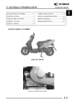
AEON MOTOR CO.,LTD
OVERLAND-125/180
SERVICE MANUAL
CONTENTS
1.
INFORMATION………………………………………... 2
2.
MAINTENANCE…………………….………………… 6
3.
ENGINE REMOVAL AND INSTALLATION…………
16
4.
ENGINE LUBRICATION AND COOLING SYSTEM..
17
5.
CYLINDER HEAD & VALVES……………………….. 26
6.
CYLINDER & PISTON………………………………... 37
7.
TRANSMISSION SYSTEM…………………………… 46
8.
FRONT WHEEL, SUSPENSION AND STEERING…..
9.
REAR WHEEL SYSTEM……………………………… 68
10.
FENDERS AND EXHAUST PIPE…………………….. 79
11.
ELECTRICAL SYSTEM………………………………. 81
12.
TROUBLE SHOOTING………………………………..
1
57
88
1. INFORMATION
1.1 Safety
1.2 Notes
1.3 Specifications
1.4 Serial number
1.5 Torque valve
1.1
Safety
GASOLINE
Gasoline is extremely flammable and is explosive under certain condition. Do not smoke or
allow sparks or flames in your work area.
CARBON MONOXIDE
Never run the engine in a closed area. The exhaust contains poisonous carbon monoxide gas
that may cause loss of consciousness and lead to death.
BATTERY ELECTROLYTE
The battery electrolyte contains sulfuric acid. Protect your eyes, skin and clothing. If you come
into contact with the electrolyte, flush the area thoroughly with water. If you get the electrolyte
in your eyes, flush with water and contact a doctor immediately.
HOT PARTS
Engine and exhaust pipe become very hot and remain hot for one hour after the engine is run.
Wear insulated gloves before handling these parts.
USED ENGINE /GEAR OIL
Used engine oil and gear oil may cause skin disease after repeated contact with the skin for
long periods. Keep out of reach of children.
1.2 NOTES
All information, illustrations, directions and specifications included in this publication are base
on the latest product information available at the time of approval for printing.
No part of this publication may be reproduced without written permission.
2
1.3 SPECIFICATION
ENGINE
Air Cleaner
Transmission
180
Air-Cooled 4-syroke
with Oil Cooler
169 cc
61×57.8mm
9.1:1
6.2 Nm@6300 min-1
MIKUNI 180
C.D.I Electronic
Electrical & Kick-Start
Wet crankcase with lobes
pump
AE-9
Automatic(C.V.T. system)
Overall Length
Overall Width
Overall Height
Wheel Base
Dry Weight
Fuel Tank Capacity
1790mm
970mm
1200mm
1050mm
156kg
8.0 liter
Front
Rear
Double wishbone
Swing Arm
Front
Rear
Drum
Disc
Front
Rear
21” × 7” - 10”
22” × 10” - 8”
Type
Displacement
Bore and Stroke
Compression
Maximum Power
Carburetor
Ignition
Starting
Lubrication
CHASSIS
SUSPENSION
BRAKES
TIRES
*Specifications subject to change without notice.
3
1.4 SERIAL NUMBER
The frame serial number is stamped on the front frame.
And stick a bar code paper to cover it.
The engine number is stamped under the crankcase.
4
1.5 TORQUE VALUES
STANDARD
5mm bolt and nut
6mm bolt and nut
8mm bolt and nut
10mm bolt and nut
12mm bolt and nut
5 N.m (3.5 lbs.ft)
10 N.m (7.2 lbs.ft)
22 N.m (16 lbs.ft)
35 N.m (25 lbs.ft)
55 N.m (40 lbs.ft)
ENGINE
Cylinder head nut
Spark plug
Cylinder head bolt
Alternator bolt
28 N.m (20.7 lbs.ft)
12 N.m (8.9 lbs.ft)
20 N.m (14.8 lbs.ft)
8 N.m (5.9 lbs.ft)
FRAME
Handlebar upper holder bolt
Throttle housing cover screw
Steering shaft nut
Steering shaft holder bolt
Wheel rim bolt
Tie rod lock nut
King pin nut
Handlebar lower holder nut
Front wheel bolt
Front axle nut
Front brake arm nut
Rear brake arm nut
Rear axle nut
Rear wheel bolt
Exhaust muffler mounting bolt
Engine hanger bolt
Rear axle holder bolt
Swingarm pivot nut
Rear shock absorber mounting nut
24 N.m (17.7 lbs.ft)
4 N.m (2.9 lbs.ft)
50 N.m (36.9 lbs.ft)
33 N.m (24 lbs.ft)
18 N.m (13.3 lbs.ft)
35 N.m (25.8 lbs.ft)
40 N.m (29 lbs.ft)
40 N.m (29.5 lbs.ft)
24 N.m (17.7 lbs.ft)
60 N.m (44 lbs.ft)
4 N.m (3.0 lbs.ft)
7 N.m (5.2 lbs.ft)
60 N.m (44.3 lbs.ft)
24 N.m (17.7 lbs.ft)
30 N.m (22.1 lbs.ft)
30 N.m (22 lbs.ft)
90 N.m (65 lbs.ft)
90 N.m (65 lbs.ft)
45 N.m (33 lbs.ft)
5
2. Maintenance
2.1
2.2
2.3
2.4
2.5
2.6
2.7
2.8
2.9
2.10
2.11
2.12
2.13
2.14
Maintenance data
Maintenance schedule
Fuel tube
Throttle operation
Throttle cable adjustment
Air cleaner
Spark plug
Idle speed
Drive chain
Brake system
Wheels and tires
Steering system
Toe-in
Gear oil
2.1 MAINTENANCE DATA
SPECIFICATION
SPARK PLUG
0.6-0.7mm
NGK C7HSA or CR7HSA
5-10mm
1800rpm
10~20mm
15-25mm
21×7-10 / 22×10-8
3±0.3psi (0.15 kgf/cm2)
5±10mm
Spark plug cap
Recommended spark plugs
Throttle lever free play:
Idle speed
Brake lever free play:
Drive chain slack
Front/rear tire size
Front/rear tire pressure
Toe-in
TORQUE VALUES
12-19 N.m
35-43 N.m
SPARK PLUG
TIE-ROD LOCK NUT
ENGINE OIL
SAE 15W-40
Viscosity:
GEAR LUBRICATION OIL
SAE 85W-140
Viscosity:
6
2.2 MAINTENANCE SCHEDULE
The maintenance intervals in the follow table is based upon average riding, condition. Riding
in usually dusty areas, require more frequent servicing.
Service Item
Initial Service
(First 30 hours)
Every 100 hours
ENGINE OIL
R
R
GEAR OIL
R
Every 200 hours
Every 300 hours
R
FUEL FILTER
R
AIR VLEAN
FILTER
R
ENGINE OIL
FILTER
C
CARBURETOR
I
SPARK PLUG
C
VALVE GAP
A
IGNITION
TIMING
A
CHAIN
A
BATTERY
I
DRIVE
BATTERY
I
CLUTCH
I
THROTTLE
OPERATE
I
TIRE
PRESSURE
Check before riding each time
BRAKE
SYSTEM
Check before riding each time
NUTS/BOLTS
A: Adjust
C: Clean
T
I: Inspection
R: Replace
7
T: Tighten
2.3 FUEL TUBE
Inspect the fuel lines for deterioration,
damage or leakage and replace if necessary.
2.4 THROTTLE OPERATION
Inspect for smooth lever operation, full opening
and automatic full closing in steering positions.
Inspect for deterioration, damage, cuts and
nicks, or kink in the throttle cable, replace it if
necessary.
Check the throttle lever, free play should be
not more than 5-10 mm at the tip of the
throttle lever.
Disconnect the throttle cable at the upper end.
Lubricate the cable with commercially
lubricant to prevent premature wear.
8
2.5 THROTTLE CABLE ADJUSTMENT
Slide the rubber cap of the adjuster off the
throttle housing, loosen the lock nut and adjust
the free play of the throttle lever by turning the
adjuster on the throttle housing. Inspect the free
play of the throttle lever.
2.6 AIR CLEANER MAINTENANCE
(1) Loosen the screw and remove the air
cleaner from carburetor.
(2) Disassemble the air cleaner cover and body.
(3) Remove the air cleaner element and screen..
(4) Install the new one.
(5) Assemble the air cleaner body and cover
and re-attach to the carburetor with screw.
9
2.7 SPARK PLUG
The spark plug is located at the front of the
engine.
(1) Disconnect the spark plug cap and remove
the spark plug
(2) Visually inspect the spark plug electrode
for wear or cranks in insulator. Replace if
needed.
(3) The center electrode should have square
edges and the side electrode should have a
constant thickness.
(4) Discard the spark plug if there is apparent
wear or if the insulator is cracked or
chipped.
(5) Measure the gap with a wire-type feeler
gauge and adjust if necessary by carefully
bending the side electrode.
SPARK PLUG GAP: 0.6~0.7 mm
RECOMMENDED REPLACEMENT PLUG:
NGK CR7HSA
(6) Check the sealing washer and replace with a
new one if damaged.
(7) With the sealing washer attached thread the
spark plug in by hand to prevent cross
threading. Tighten the spark plug. TORQUE:
12-19 N-m
2.8 IDLE SPEED SETTING
(1) Inspect and adjust the idle speed after all
other engine maintenance items have been
performed and are within specifications.
The engine must be warm for accurate idle
speed inspection and adjustment.
(2) Warm up the engine for about ten minutes
and connect a tachometer.
(3) Turn the throttle stop screw as required to
obtain the specified idle speed.
IDLE SPEED: 1700 ± 100 rpm
10
2.9 DRIVE CHAIN ADJUSTMENT
Stop ATV and shift transmission into neutral.
Inspect the chain slack midway between the
sprockets. The standard is 10-25 mm (5/8-1
inch).
If needed remove the chain protective cover
and adjust the chain slack.
Loosen the axle holder lock nut then adjust the
drive chain slack by turning the adjusting nut.
Tighten the axle holder lock nut.
Torque = 90N.m (65 Ft. lbs)
When the drive chain becomes very dirty, it
should be removed, cleaned and lubricated with
the specified lubricant.
Clean the drive chain with kerosene and wipe it
dry.
Inspect the drive chain for possible wear or
damage.
Replace the chain, if it is worn excessively or
damaged.
Inspect the sprocket teeth, if it has excessive
wear or damage, replace if needed.
Use a commercial chain lubricant to lubricate
the drive chain, replace and adjust the slack as
described above.
11
2.10 BRAKE SYSTEM ADJUSTMENT
Inspect the front brake lever and cable for
excessive play or other damage.
Replace or repair if necessary.
Measure the free play of the brake lever at the
end of the lever. The standard is 10~20 mm.
Adjust the free play of the front brake lever by
turning the adjuster on the brake lever
assembly.
Inspect the rear brake lever and cable for
excessive play or other damage.
Replace or repair if necessary.
Measure the free play of the brake lever at the
end of the lever. The standard is 10-20 mm.
Adjust the free play of the rear brake lever by
turning the adjuster on the rear axle.
BRAKE SHOE WEAR
Front Brake
Release the front wheel and inspect the brake
lining thickness. Service Limit: 2.0mm (0.08
inch), if either lining is worn beyond the
service limit, replace both brakes shoes.
12
2.11 WHEELS AND TIRES
Inspect the tire surface for cuts, nails or other
sharp objects.
Check the tire pressure at cold tire conditions.
The standard tire pressure is 3psi.
(0.15kgf/cm2 )
2.12 STEERING SYSTEM
Check the free play of the steering shaft with
the front wheels, turned straight ahead. When
there is excessive play, inspect the tie-rod,
kingpin bushing and ball joint.
Steering shaft holder bushing
Remove the front fender.
Remove the steering shaft holder and check the
steering shaft bushing for wears or damage.
If the bushing is worn or damaged, change a
new one.
Grease the steering shaft bushing and install the
parts in the reverse order of removal.
Torque: steering shaft holder bolt: 33N.m ( 24
Ft. lbs)
13
2.13 TOE-IN
Park the vehicle on level ground with the front
wheels facing straight ahead.
Mark the centers of the tires to indicate the axle
center height.
Measure the distance between the marks.
Carefully move the vehicle back, let the wheels
turn 180° so the marks on the tires are aligned
with the axle center height.
Measure the distance between the marks.
Calculate the difference in the front and rear
measurements.
Toe-in: 5±10 mm
If the toe-in is out of standard, adjust it by
changing the length of the tie-rods equally by
turning the tie-rod while holding the ball joint.
Tighten the lock nuts.
Torque: 35-43 N.m
14
2.14 GEAR OIL MAINTENANCE
Gear oil needs to be changed every 200 hours.
There is a gear oil drain hole bolt at the rear of
the engine.
(STEP1)
Unscrew this drain hole bolt and let the dirty oil
flow out, catching the oil in a proper container
for later disposal.
(STEP2)
Reinstall the drain hole bolt an tightness.
(STEP3)
Fill with new gear oil through the oil fill hole
located on the engine case beside the gear box.
15
3.1 ENGINE REMOVAL AND INSTALLATION
ENGINE SHOULD ONLY BE REMOVED IN THE CONDITIONS OF NECESSARY
REPAIRS OR ADJUSTMENT TO THE TRANSMISSION AND COMBUSTION SYSTEM
ONLY!
3.2 ENGINE REMOVAL
Remove the front, rear rack, and handle bar.
Remove the footrest.
Remove the spark plug cap from the spark plug.
Remove the exhaust muffler.
Disconnect the carburetor cable by unscrew two
screws on top of the carburetor.
Disconnect the wire connectors. There are three
connectors for carburetor auto-choke, starter
motor and generator respectively.
Remove the engine hanger bolts over the engine.
Remove the engine and air cleaner together.
3.2 ENGINE REPLACEMENT
Engine installation is essentially the reverse
order of removal.
The torque of engine hanger bolt is 30 Nm
Route the wires and cable properly in reverse
order of removal.
16
4. LUBRICATION
4.1 Service Information
4.2 Trouble Shooting
4.3 Engine Oil Level
4.4 Engine Oil & Filter Change
4.5 Oil Pump Removal /Installation
4.1 SERVICE INFORMATION
GENERAL
This section describes inspection and replacement of the engine oil, oil filter screen and
assembly of the oil pump.
Fill the oil pump with clean oil when reassembling the pump.
SPECIFICATIONS
Engine Oil Capacity
Engine Oil Recommendations
0.8-1.0 Liters /
Viscosity: (SAE 15W-40)
API Service classification: SF-SG
17
OIL PUMP
STANDARD
Cover-to-rotor clearance
Rotor tip clearance
End clearance
SERVIC
---------------0.01-0.10
TORQUE VALUE
Oil Drain Bolt
20~30 N.m (14.8~22.1 lbs.ft)
4.2 THROTTLE SHOOTING
Oil level too low / high oil consumption
Normal oil consumption.
External oil leaks.
Oil not changed often enough.
Worn piston rings.
Faulty heat gasket.
Oil contamination
Worn piston rings.
Faulty heat gasket.
Oil or filter not changed often enough.
4.3 ENGINE OIL LEVEL
Place the engine on the level plane.
Check the oil level with the oil level gauge,
but do not screw it in when making this
check.
18
LIMIT
0.12
0.12
0.2
4.3 ENGINE OIL LEVEL
Add the recommended oil up to the upper
level if the oil level is below or near
lower level line on the gauge.
LOWER LEVEL
UPPER LEVEL
4.4 ENGINE OIL & FILTER CHANGE
Remove the oil filter cap and the oil drain bolt.
NOTE: drain the oil while the engine is warm to
ensure complete draining.
OIL DRAIN
Remove the oil filter cap, spring and oil filter
screen.
OIL FILTER SCREEN
OIL FILTER
Check the O-ring for damage or fatigue.
Install a new oil filter screen and spring then
install the cap.
SPRING
19
O-RING
Install the oil drain bolt with sealing washer.
TORQUE: 20~30 N.m (14.8~22.1 lbs.ft)
Fill the crankcase with recommended oil.
ENGINE OIL CAPACITY: 1.2 liter at draining.
OIL DRAIN
Install the oil filter cap.
Install the oil level gauge.
Start the engine and let it idling for 2 or 3
minutes.
Stop the engine and check that the oil level at the
upper line on the gauge. Make sure there are no
oil leaks.
4.5 OIL PUMP REMOVAL
Remove the fan cover ass’y.
OIL FILTER
CAP
FAN COVER ASS’Y
Remove the cooling fan composition.
COOLING FAN COMPOSITION
20
Remove the A.C.G generator ass’y.
Remove the left crankcase cover.
Remove the starting clutch outer and gear ass’y.
Remove the flange bolts and oil separator.
21
Remove the oil pump chain and oil pump driven
sprocket.
Remove the oil pump ass’y.
Disassemble the oil pump.
INSPECTION
Measure the oil pump rotor-to-body clearance.
SERVICE LIMIT: 0.12 mm
22
Install the oil pump shaft and measure the pump
rotor tip clearance.
SERVICE LIMMIT: 0.12 mm.
Remove the oil pump shaft and measure the
pump and clearance.
SERVICE LIMMIT: 0.2 mm.
4.5 OIL PUMP ASS’Y / INSTALLATION
Install the outer rotor, inner rotor and oil pump
shaft onto the body.
NOTE: Pour a drop of clean engine oil inside
the oil pump.
Install the oil pump ass’y
23
Install the oil pump driven sprocket and oil
pump chain.
Install the oil separator.
Install the starting clutch outer and gear ass’y.
Install the new gasket, dowel pins and right crankcase cover.
24
Install the A.C.G generator ass’y
Install cooling fan composition
Install fan cover
25
5. CYLINDER HEAD / VALVES
5.1 SERVICE INFORMATION
5.2 TROUBLESHOOTING
5.3 CAMSHAFT ASS’Y REMOVAL
5.4 CYLINDER HEAD REMOVAL
5.5 CYLINDER HEAD INSTALLATION
5.1 SERVICE INFORMATION
GENERAL
This section describes the maintenance of cylinder head, valves, camshaft and the other parts.
The engine must be removed from the frame to service cylinder head.
Camshaft lubrication oil is fed to the cylinder head through an oil orifice in the engine case.
Before installing the cylinder head be sure the orifice is not clogged and the gasket, O-ring and
dowel pins are in place.
SPECIFICATIONS
ITEM
Cylinder compression
Cam lobe height
Rocker arm I.D.
Rocker arm shaft O.D.
Valve spring free length
Valve stem O.D.
Valve guide I.D.
Stem-to-guide clearance
Valve seat width
IN
EX
STANDARD
12±0.5 kg/cm2
25.965/27.195
25.810/27.20
10.000-10.018
9.972-9.987
32.3
35.0
SERVICE LIMIT
--------25.57/26.7
25.40/26.80
10.10
9.91
31.2
34.1
IN
EX
IN/EX
IN
EX
IN
EX
4.975-4.990
4.955-4.970
5.000-5.012
0.010-0.037
0.030-0.057
1. 0
1.0
4.90
4.90
5.30
0. 08
0.10
1. 8
1.8
IN
EX
TORQUE VALUES
Cylinder head bolts
Camshaft holder flange nuts
Tappet adjusting nut
8~12 N.m (5.9~8.9 lbs.ft)
20~24 n-m (14.8~17.8 lbs.ft)
9~12 n-m (6.6~8.9 lbs.ft)
26
5.2 TROUBLE SHOOTING
Engine top-end problems usually affect engine performance. These problems can be diagnosed
by a compression test, or by tracing engine noise to the top end with a sounding rod or
stethoscope.
Low compression valve
Incorrect valve adjustment.
Worn or damaged valve seats.
Burned or bent valve.
Incorrect valve timing.
Weak valve spring.
Cylinder head
Leaking or damaged head gasket.
Warped or cracked cylinder head.
Faulty cylinder or piston
Excessive noise
Incorrect valve adjustment
Sticking valve or broken valve spring.
Worn or damaged rocker arm or camshaft.
Worn or damaged cam chain.
Worn or damaged cam chain tensioner.
Worn cam sprocket teeth.
Excessive smoke
Damaged valve stem seal.
Faulty cylinder or piston rings.
27
5.3 CAM SHAFT ASS’Y REMOVAL
Remove the rubber tube of gas waste recovery.
Remove the cylinder head cover.
Remove the air cleaner and carburetor.
Remove the inlet pipe ass’y.
Remove the shroud compositions.
Relax the cam chain adjuster screw.
28
Remove the screw and O-ring and tighten the
cam chain-adjusting bolt with clockwise
direction.
Remove the nuts and washers
Remove the camshaft holder and dowel pins.
Relax the camshaft gear from cam chain and
remove the camshaft.
INSPECTION
Inspect the cam lobes surface and height of cam
lobes for wear or damage.
SERVICE LIMIT: IN:25.57/26.18 mm
EX:25.41/26.02 mm
29
Inspect the camshaft and bearings for wear or
damage and replace them if necessary.
Screw a 5 mm bolt into the rocker arm shaft
threaded end. Pull on the bolt to remove the
shafts and rocker arms.
Inspect the camshaft holder, rocker arms and
rocker arm shafts for wear or damage.
Measure the I.D. of each rocker arm.
SERVICE LIMIT: 10.10 mm
Measure the O.D. of each rocker arm shaft.
SERVICE LIMIT: 9.91 mm
30
5.4 CYLINDER HEAD REMOVAL
Remove the flange bolts and cylinder head.
Remove the cylinder head gasket and dowel
pins.
Remove the cam chain guide.
CYLINDER HEAD DISASSEMBLY
Remove the valve cotters, spring retainers and
valve springs with a valve spring compressor.
31
INSPECTION
Clean off all carbon deposits from the combustion and check the spark plug hole and valve
area for cracks.
Measure the cylinder head diagonally for warp
with a straight edge and feeler gauge.
Measure the free length of the inner and outer
valve springs.
SERVICE LIMITS: Inner 31.2 mm
Outer 34.1 mm
Inspect each valve for turning, burning,
scratches or abnormal stems wear.
Check the valve movement in the guide.
32
Measure and record each valve stem O.D.
SERVICE LIMITS: 4.90 mm
Measure and record the valve guide I.D.
SERVICE LIMITS: IN / EX 5.30 mm
Calculate the stem-to-guide clearance.
SERVICE LIMITS: IN 0.08 mm
EX 0.10 mm
NOTE: If the stem-to-guide clearance exceeds
the service limits, determine if a new guide with
standard dimensions would bring the clearance
within tolerance.
If so, replace guides as necessary and ream to fit.
If the valve guide is replaced, the valve seat
must be refaced.
CYLINDER HEAD ASS’Y
Lubricate each valve stem with oil.
Insert the valves into the guides.
Install the valve springs, retainers and the
cotters.
NOTE: To prevent loss of tension, don’t
compress the valve springs more than necessary.
INSTALLATION
Install the new gasket and dowel pins.
33
Install the cam chain guide.
Install the cylinder head.
CAMSHAFT ASS’Y INSTALLATION
Install the rocker arms and rocker arm shafts
into the camshaft holder.
Align the “T” mark on the flywheel with the
index mark on the alternator cover by turning
the flywheel counter-clockwise.
34
Position the camshaft gear with cam chain so
that its “I” mark aligns with the cylinder head
surface and the circle hole towards the front.
Install the dowel pins and camshaft holder.
Tighten the washers and nuts.
Torque: 20 N.m (14.8 lbs.ft)
Adjust the clearance between the rocker arm
and valve stem by applying a feeler gauge.
STANDARD VALVE: 0.08 mm
Relax the cam chain-adjusting bolt with counterclockwise direction and install the o-ring and
screw.
35
Install the cylinder head cover.
CYLINDER HEAD COVER
36
6. CYLINDER AND PISTON
6.1 SERVICE INFORMATION
6.2 TROUBLESHOOTING
6.3 CYLINDER REMOVAL
6.4 PISTON REMOVAL
6.5 CYLINDER INSTALLATION
6.1 SERVICE INFORMATION
GENERAL
Camshaft lubrication oil is fed to the cylinder head through an oil orifice in the cylinder head
and engine case. Before installing the cylinder head be sure the orifice is not clogged and the
gasket, O-ring and dowel pins are in place.
SPECIFICATION
ITEM
Cylinder
STANDARD
SERVICE LIMIT
52,400-52,410/
61,730-61,740
52.50/
61.830
Taper
----------
0.10
Out of round
----------
0.10
Warp across top
----------
0.10
I.D.
Piston
Piston O.D.
52,370-52,390
61,700-61,720
52,3/
61,63
Piston pin
Piston pin bore
15.002-15.008
15.04
Piston rings
Piston pin O.D.
14.994-15.000
14.960
0.002-0.014
0.02
TOP
0.015-0.050
0.12
SECOND
0.015-0.050
0.12
Groove Clearance
TOP/SEC
0.10-0.25
0.5
Piston ring end gap
OIL
0.2-0.7
----------
Cylinder-to-piston clearance
0.0005-0.1025
0.1
Connecting rod small end I.D.
15.010-15.028
15.06
Piston-to-pin clearance
Piston ring
TORQUE VALUES
Cylinder head bolts
Camshaft holder flange nuts
Tappet adjusting nut
8~12 N.m (5.9~8.9 lbs.ft)
20~24 N.m (14.8~17.7 lbs.ft)
9~12 N.m (6.6~8.9 lbs.ft)
37
6.2 TROUBLESHOOTING
Low or unstable compression
Worn cylinder or piston rings.
Overheating
Excessive carbon build-up on piston or combustion chamber wall.
Knocking or abnormal noise
Worn piston and cylinder.
Excessive carbon build-up.
Excessive smoke
Worn cylinder, piston, or piston rings.
Improper installation of piston rings
Scored or scratched piston or cylinder wall.
Damaged valve stem seal.
38
6.3 CYLINDER REMOVAL
Remove the cylinder head.
Remove the cylinder.
Remove the cylinder gasket and dowel pins.
Clean off any gasket materials from the cylinder
surface.
NOTE: Be carefully not to damage the gasket
surface.
39
6.4 PISTON REMOVAL
Stuff a shop towel into the crankcase.
Remove the piston pin clip with needle nose
pliers.
NOTE: Do not allow the clip fall into the
crankcase.
Remove the piston pin from the piston.
Remove the piston.
Spread each piston ring and remove it by lifting
up at a point opposite the gap.
INSPECTION
Inspect the cylinder walls for scratches or wear.
40
Measure and record the cylinder I.D. at three
levels in both an X and Y axis. Take the
maximum reading to the cylinder wear.
SERVICE LIMITS: 0.10 mm
Calculate cylinder taper at three levels in an X
and Y-axis. Take the maximum reading to
determine the out-of-round.
SERVICE LIMITS: 0.10 mm
Inspect the top of the cylinder for warp.
SERVICE LIMITS: 0.10 mm
PISTON / PISTON RING INSPECTION
Measure the piston ring-to-groove clearance.
SERVICE LIMITS: TOP 0.12 mm
SECOND 0.12 mm
41
Inspect the piston for wear or damage.
Insert each piston ring into the cylinder and
measure the ring end gap.
NOTE: Push the rings into the cylinder with the
top of the piston to be sure they are squarely set
in the cylinder,
SERVICE LIMITS: TOP 0.5 mm
SECOND 0.5 mm
Measure the piston pin O.D.
SERVICE LIMIT: 14.960 mm
Measure the piston pin O.D.
SERVICE LIMIT: 15.04 mm
42
Calculate the piston-to-piston pin clearance.
SERVICE LIMITS: 0.02 mm
Measure the connecting rod small end I.D.
SERVICE LIMITS: 15.06 mm
6.5 PISTON &
PISTON RING INSTALLATION
Clean the piston ring grooves thoroughly and
install the piston ring with the marks facing up.
NOTE: Don’t interchange the top and second
rings. Avoid piston and piston ring
damage during installation.
Space the piston ring end gaps 120 degrees
apart.
43
PISTON INSTALLATION
Install the piston with it’s “IN” mark on the
intake valve.
Install the piston pin with new pin clips.
Do not align the piston pin clip end gap with the
piston cutout.
NOTE: do not allow the clip to fall into the
crankcase.
6.6 CYLINDER INSTALLATION
Clean any gasket material from the crankcase
surface.
NOTE: Be carefully not to damage the gasket
surface.
Install the dowel pins a new gasket.
44
Coat the cylinder bore and piston rings with
engine oil and install the cylinder.
NOTE: Avoid piston rings damage cylinder bore
during installation. Do not allow the cam chain
fall into the crankcase.
Install the cylinder head.
45
7. TRANSMISSION & KICK STARTER
7.1 SERVUCE INFORMATION
7.2 TROUBLE SHOOTING
7.3 C.V.T DISASSEMBLY
7.4 KICK STARTER DISASSEMBLY
7.5 KICK STARTER ASSEMBLY
7.6 C.V.T ASSEMBLY
7.1 SERVICE INFORMATION
If the drain tube ass’y fills with water, the tube should be drained.
SPECIFICATIONS
ITEM
STANDARD (mm)
SERVICE LIMIT (mm)
Driven the width
19.8-20.2
19.0
Weight roller O.D.
15.0-15.02/17.0-17.02
14.6/16.6
Movable drive face I.D.
27.98-28.0
28.03
Drive face collar I.D.
24.06-24.09
24.098
Drive face boss O.D.
23.96-23.98
23.92
Clutch outer I.D.
124.8-125.2
125.5
Clutch weight lining thickness --------------
1.5
Driven face spring length
164.0
TORQUE VALUES
Clutch outer nut
Drive face nut
168.4-169.4
55 N-m (40.6 lbs.ft)
55 N-m (40.6 lbs.ft)
46
7.2 TROUBLE SHOOTING
Engine starts but can’t travel
Worn driven belt.
Worn clutch lining.
Damaged driven face spring.
Low engine power
Worn driven belt.
Worn weight roller.
Dirty driven face.
47
7.3 C.V.T DISASSEMBLY LH
CRANKCASE COVER REMOVAL
C.V.T INLET DUCT
Relax the band screw and remove the C.V.T
inlet duct.
Remove the air cleaner case.
AIR CLEANER CASE
Remove the bolts and LH crankcase cover.
LH CRANKCASE COVER
48
Remove the gasket and dowel pins.
Clean off any gasket material from L crankcase
surface.
GASKET
DOWEL PINS
FLANGE NUT
LH CRANKCASE SURFACE
C.V.T REMOVAL
Relax the flange nut, and remove the drive face.
DRIVE FACE
Relax the flange nut.
Remove the drive pulley ass’y and driven belt.
FLANGE NUT
FLANGE BELT
Remove the drive face boss and movable driven
face ass’y.
DRIVE FACE BOSS
MOVABLE DRIVEN FACE
49
DRIVE PULLEY
Remove the ramp plate and weight roller set.
Relax the special nut and remove the driven
plate composition and driven face spring.
INSPECTION
Inspect the driven belt for wear, tears or
damage. Measure the width of driven belt.
SERVICE LIMIT:19.0 mm
Inspect the weight roller for wear or damage
and replace them if necessary.
Measure the O.D. of weight rollers.
SERVICE LIMIT:14.6/16.6 mm
50
Measure the I.D. of movable driven face.
SERVICE LIMIT:28.03mm
Inspect the drive face collar for wear or
damage.
Measure the I.D. of drive face collar.
SERVICE LIMIT:24.098 mm
Inspect the drive face boss for wear or damage.
Measure the O.D. of drive face boss.
SERVICE LIMIT:23.92 mm
Inspect the clutch outer for wear or damage.
Measure the I.D. of clutch outer.
SERVICE LIMIT:125.5 mm
Inspect the clutch weight set for wear or
damage.
Measure the thickness of clutch weight lining.
SERVICE LIMIT:1.5mm
51
Measure the length of driven face spring.
SERVICE LIMIT:164.0 mm
Inspect the driven face ass’y and replace them
if necessary.
7.4 KICK STARTER DISASSEMBLY
Remove the LH crankcase cover.
Remove the kick starter.
KICK STARTER
LH CRANKCASE COVER
Remove the ex. Circle-clip and washer from
kick starter spindle composition.
EX. CIRCLIP
52
Remove the kick-starter spindle ass’y.
Remove the kick-starter idle gear ass’y
Remove the kick spindle bush.
STARTER SPINDLE ASS’Y
INSPECTION
Inspect the kick-starter spindle composition for
wear or damage.
Inspect the kick-starter return spring for
fatigue or damage.
Inspect the kick-starter spindle bush for wear of
damage.
STARTER IDLE GEAR ASS’Y
KICK SPINDLE BUSH
KICK RETURN SPRING
Inspect the kick driven gear and spring for
wear or damage.
KICK DRIVEN SPRING
53
7.5 KICK-STARTER ASSEMBLY
Install the kick driven gear and spring.
Install the kick spindle bush, return spring and
spindle ass’y.
Install the kick-starter.
KICK STARTER
7.6 C.V.T ASSEMBLY
Assemble the driven face ass’y, spring and
driven plate.
54
Assemble the movable drive face, weight
roller set and drive face.
Install the movable drive face ass’y and boss.
DRIVE FACE BOSS
MOVABLE DRIVEN FACE
Install the drive face and kick starter ratchet.
FLANGE NUT
DRIVE FACE
Install the driven belt and driven pulley ass’y.
FLANGE NUT
DRIVEN BELT
55
DRIVE PULLEY
Install the dowel pins and gasket.
GASKET
DOWEL PIN
Install the LH crankcase cover.
LH CRANKCASE COVER
Install the air cleaner case and C.V.T ducts.
56
8. FRONT WHEEL, SUPENSION AND STEERING
8.1 PARTS DRAWING
8.2 TROUBLESHOOTING
8.3 HANDLEBAR
8.4 THROTTLE HOUSING
8.5 FRONT WHEEL
8.6 FRONT BRAKES
8.7 STEERING SYSTEM
8.8 FRONT SUSPENSION
8.1 PARTS DRAWING
57
58
8.2 TROUBLESHOOTING
HARD STEERING
Faulty tire
Steering shaft holder too tight
Insufficient tire pressure
Faulty steering shaft bushing
Damaged steering shaft bushing
FRONT WHEEL WOBBLING
Faulty tire
Worn front brake drum bearing
Bent rim
Axle nut not tightened properly
BRAKE DRAG
Incorrect brake adjustment
Sticking brake cable
STEERS TO ONE SIDE
Bent tie rods
Wheel installed incorrectly
Unequal tire pressure
Bent frame
Worn swing arm pivot bushing
Incorrect wheel alignment
POOR BRAKE PERFORMANCE
Brake shoes worn
Worn brake drum
Brake lining oily, greasy or dirty
Improper brake adjustment
FRONT SUSPENSION
Loose front suspension fastener
Binding suspension link
HARD SUSPENSION
Faulty front swing arm bushing
Improperly installed front swing arms
Bent front shock absorber swing rod
SOFT SUSPENSION
Wear front shock absorber springs
Worn or damage front swing arm bushing
59
8.3 HANDLEBAR SYSTEM
Removal
Remove the handlebar cover by unscrew two fix
screws.
Remove the throttle lever housing on the right
handlebar. Remove brake lever bracket
assembly.
Remove the handlebar switch on the left handle
bar. Remove rear brake lever bracket ass’y.
Remove the bolts attaching the handlebar upper
holder. Remove the handlebar.
60
Installation
Install the switch housing. Tighten two screws
securely.
Install the throttle lever housing, and brake lever
bracket ass’y.
61
8.4 THROTTLE HOUSING
Disassembly
Unscrew the screws on the throttle housing
cover.
Remove throttle housing cover and gasket.
Disconnect throttle cable from the throttle arm
and remove from the throttle housing.
Assembly is in the reverse order of disassembly.
8.5 FRONT WHEEL
Remove
Raise the front wheels off the ground by placing
a jack or other support under the frame.
Remove the front wheel nuts, washer and
wheels.
Installation
Install and tighten the four-wheel nuts torque:
60 N.m (44 lbs.ft ) Remember put a cotter pin in
the castle nut.
8.6 FRONT BRAKES
Front brake inspection
Remove the front wheel
Remove the brake drum.
Measure the brake lining thickness. The
minimum limit: 1.5 mm
If they are thinner than the minimum limit,
replace the brake lining.
62
Measure the brake drum inner diameter.
The maximum limit: 111 mm.
Turn the inner race of each bearing with fingers.
The bearings should turn smoothly and quietly.
If the race does not turn smoothly or quietly,
remove and discard the bearings.
Brake panel removal
Disconnect the brake cable from the brake arm.
Remove the brake panel from the knuckle.
Remove brake arm and cam.
Remove return spring.
Remove indicator plate and felt seal.
63
Install Brake panel
Apply grease to the brake cam and anchor pin
and install the cam in the brake panel.
Soak the felt seal in the engine oil and install the
seal on the brake cam.
Install the brake arm on the cam by aligning the
punch mark and the groove on the cam.
Tighten the brake arm bolt and nut.
Torque : 4-7 N.m
Install the return spring.
Install the brake panel on the knuckle.
Connect the brake cable to the brake arm.
Install the brake arm cover
Tighten the screws securely
Position the brake shoes in their original
locations and install the brake shoe spring.
Install the brake drum and front wheel.
Install the castle nut and cotter pin.
64
8.7 STEERING SYSTEM
Remove the kingpin and Tie-rod
Remove the front wheels and brakes plates.
Remove the four self-lock nuts from the tie-rod
ball joints and take off the two tie-rods.
Remove the cotter pin on the kingpin.
Unscrew the bolt and remove the kingpin.
Tie-rod inspection
Inspect the tie rod for damage or bending.
Inspect the ball joint rubbers for damage, wear
or deterioration. Turn the ball joints with fingers.
The ball joints should turn smoothly and quietly.
Kingpin inspection
Inspect the kingpin for damage or cracks.
65
Steering shaft removal
Remove the handle bar cover and handle bar.
(see page 58)
Remove the front fender. (see page 72)
Remove handlebar lower holder.
Unscrew steering shaft holder bolt, remove
steering shaft holder.
Take off the cotter pin below steering shaft.
Unscrew the steering shaft fix out below shaft.
Pull steering shaft carefully.
Steering shaft holder inspection
Remove the steering shaft.
Remove the bushing from the shaft.
Inspect the bushing for damage or wear, replace
if necessary.
Measure the bushing inner diameter.
Maximum limit: Ø39.5 mm
Steering shaft inspection
Inspect the steering shaft for damage or cracks.
Installation of steering shaft
Apply grease to the holder. Install the holder
and oil seal tighten with the nuts.
Torque : 33 N.m(24 lbs-ft)
66
8.7 STEERING SYSTEM
Installation of steering shaft
Install the steering shaft nut and tighten it.
This nut is under this steering shaft.
Torque : 50 N.m (37 lbs.ft)
Installation of Tie-rod
Install the tie-rod on the wheel side.
Installation is in the reverse order of removal.
67
9. REAR WHEEL SYSTEM
9.1 PARTS DRAWING
9.2 TROUBLESHOOTING
9.3 REMOVE REAR WHEEL AND REAR BRAKE
9.4 DRIVE MECHNISM
9.5 REAR BRAKE AND WHEEL INSTALLATION
9.1 Parts Drawings
9.2 Troubleshooting
68
Bad Brake Performance
Vibration or wobble
Brake Drag
Hard Suspension
Soft Suspension
Brake shoes are worn
Bad brake adjustment
Brake lining are oily, greasy or dirty
Brake drums are worn
Brake arm setting is improperly engage
Axle is not tightened well
Bent rim
Axle bearings are worn
Faulty tires
Rear axle bearing holder is faulty
Incorrect brake adjustment
Sticking brake cam
Sticking brake cable
Bent damper rod
Faulty swing arm pivot bushing
Wear shock absorber damper
Wear shock absorber spring
9.3 REMOVE REAR WHEEL & REAR BRAKE
Loosen the cotter pin, and wheel nuts, raise the
rear wheel off the ground by placing a support
under the frame.
Release the wheel and wheel hub.
Brake Parts & Location
Handlebar
Rear Brake Cable
Front Brake Cable*2
Front Brake
Foot Brake Padal
Hydraulic Cylinder Driving Rod
Brake Pump
Wire
Connector
Rear Brake
Caliper
Rear Brake Oil Tube
69
The cable connectsto
the left side brake
lever.
The cable connects
to wire connector
for front brake
function.
Hydraulic Cylinder
Driving Rod
The rear brake
cable fixing set
Brake Pump
Brake Oil Tank
Left Side
Brake Lever
Right Side
Brake Lever
70
Wire Connector
The cable connects to
front brake drum.
Brake Oil Tube
Rear Brake
Caliper
71
The Brake Adjustment
Pan
Phillips Bolts (93100-05016-K), Plain Washer(94101-0514010-K), Nylon Lock Nut(90350-05000-K)
10 sets
Hex Flange Bolt (96000-08012-K) × 4
STEP.1) Take off the right side footwell for adjustment.
72
×
Rear Brake Cable
Fixing Set
STEP.2) Take off the rear brake fixing set and the bolt of brake pump.
Hydraulic Clyinder Driving Rod
Adjusting Bolt
73
STEP.3) The setup of the adjusting nut of the brake pump:
1)The brake pedal should be in the highest location under the function of the returning
spring.
2)The adjusting nut changes the distance between the brake pump and the hydraulic
cylinder driving rod. Make the nut touch the surface of the rod and revolve 1 circle
(360°), then confirm the nut location and spin the rod till the nut is locked.
3)Notice: If adjust the nut over 1 circle, it might result in the brake pump malfunction
and jam the brake.
STEP.4) Drain the air in the brake oil tube in order to prevent the brake pump
malfunction in power delivering.
1).Open the brake oil tank, lose the drain screw of the brake caliper without braking
motion. It functions normal if the brake oil could drain automatically, please try this for
couple times for confirmation. If it doesn’t work, please be back to STEP 3. and
decrease the distance until the oil could run out normally.
2). Press on the brake pedal or the brake lever for several times then hold press,
release the drain screw and lock it on immediately until no air bubble in the brake oil.
Be careful for the splashing oil when operating.
74
Adjusting
Screw
Brake Cable
G
Adj
Rear Brake
Cable Fixing Set
Gap(2~3mm)
STEP.5) Install the rear brake cable fixing set & adjust the brake cable.
1).Spin the gap adjuster on the left lever till the shortest position.
2).Adjust the adjusting screw and keep the gap being 2-3 mm.
Front / Rear Brake
Ratio Distribution.
Front Brake
Balance Adjustment
STEP.6) Wire Connector Adjustment:
1).The distribution of front / rear brake force on left lever.
75
2).The balance adjustment of left / right front brake.
Left / Right Front Brake
Balance Adjuster.
STEP.7) The brake balance adjuster on right lever.
76
9.4 DRIVE MECHNISM
Removal and inspection.
Remove the rear wheel and the rear brake.
Remove the skid plate under swing arm.
Remove the drive chain cover.
Disassemble the chain retaining clips and master link. Remove the chain.
Disassemble the driven sprocket, axle and
sprocket collar.
Check the driven sprocket for damage or wear.
Replace if necessary.
Let the rear axle lie in V-blocks and check the
runout.
The runout limit is 0.5 mm.
Check the turning of inner race of bearing with
77
fingers. The bearings should turn smoothly and
quietly. Replace if necessary.
Also check that the bearing outer race fits tightly
in the axle holder. Replace if necessary.
NOTE: Replace the bearings in pairs.
Installation
Add grease to the dust seal lips and install dust
seals. Assemble the rear axle and the driven
sprocket.
Assemble the drive chains on the driven sprocket. Assemble the master link and retaining clip.
NOTE: The retaining clip direction.
Install the drive chain cover.
Assemble the chain under cover.
Install the skid plate.
Install the drive chain cover.
78
10. FENDER AND EXHAUST PIPE
10.1 REAR FENDER REMOVAL
Pull the “Seat Release Bar” to take off the seat.
This seat release bar is under the right side of the
rear fender.
Procedure for rear fender removal:
Remove the rear rack and seat.
Unscrew the four bolts, which connect the front
fender and rear fender.
Unscrew the four screws, which connect the rear
fender and frame.
Unscrew the six screws, which connect with
footrest plate. Pull the rear fender backward so the
rear fender can be removed.
10.2 FRONT FENDER REMOVAL
After remove the rear fender, remove the two
front fender mounting bolts from front frame.
Remove the fuel tank cap.
79
Remove the mounting bolts and nuts from the
front fender and footrest plate.
10.3 EXHAUST PIPE REMOVAL
You must wait at least 15 minutes after turn off
the engine. You need to remove the seat, rear
fender and footrest plate, before you take off the
exhaust pipe. Unscrew the two exhaust pipe
bolts that fixed with engine.
NOTE: Do not service the exhaust pipe while
they are hot.
Remove the exhaust pipe bolts mounting on the
frame below the rear fender.
Remove the exhaust pipe carefully.
10.4 EXHAUST PIPE INSTALLATION
Installation is the reverse order of removal.
Torque: Exhaust muffler bolts 30 N.m (22 lbs.ft)
NOTE: After installation, check entire system to
make sure that there are no exhaust leaks.
80
11. ELECTRICAL SYSTEM
11.1 TROUBLESHOOTING
11.2 IGNITION COIL
11.3 IGNITION TIMING
11.4 ALTERNATOR EXCITER COIL
11.5 BATTERY CAUTION
11.6 BATTERY VOLTAGE
11.7 CHARGING
11.8 ELECTRIC STARTER
11.9 LIGHT BULBS REPLACEMENT
11.10 WIRING DIAGRAMS
11.1 Troubleshooting
ENGINE STARTS BUT STOPS
IMPROPER IGNITION TIMING
FAULTY SPARK PLUG
NO SPARK AT PLUG
ENGINE STOP SWITCH AT LEFT OR
RIGHT POSITION
GEARSHIFT BAR IS NOT AT NEUTRAL
POSITION
FAULTY IGNITION COIL
FAULTY GENERATOR
FAULTY CDI UNIT
POORLY CONNECTED:
Between CDI and ignition coil
Between alternator and CDI unit
Between CDI and engine stop switch
Between ignition coil and spark plug
Between generator and CDI unit
ENGINE STARTS BUT RUNS
POORLY
IGNITION PRIMARY CIRCUIT
Faulty generator
Faulty CDI unit
Faulty alternator
Loosen contacted terminals
Faulty ignition coil
IGNITION SECONDARY CIRCUIT
Faulty plug
Loosen contacted spark plug wire
IMPROPER IGNITION TIMING
81
Faulty generator
Faulty CDI unit
CHARGING SYSTEM FAILURE
LOOSE, BROKEN OR SHORTED WIRE.
FAULTY ALTERNATOR
FAULTY IGNITION SWITCH
INTERMITTENT ENGINE POWER
LOOSE BATTERY CONNECTION
LOOSE CHARGING SYSTEM CONNECTION
STARTER MOTOR WILL NOT TURN
DEAD BATTERY
FAULTY IGNITION SWITCH
LOOSE OR DISCONNECTED WIRE
STARTER MOTOR AND ENGINE TURN, FAULTY IGNITION SYSTEM
BUT ENGINE DOES NOT START
FAULTY ENGINE STOP SWITCH
ENGINE PROBLEMS
HEAD LIGHT DO NOT WORK
THE SWITCH DO NOT PUSH TO THE “ON”
POSITION
THE LIGHT BULB IS BURN OUT, NEED BE
REPLACED
11.2 IGNITION COIL
Remove the spark plug cap from the spark plug.
Disconnect the ignition coil primary wire.
Measure the primary coil resistance.
STANDARD: 0.1-0.30Ω
Measure the secondary coil resistance with the spark
plug cap in place.
STANDARD: 7.4-11 KΩ
11.3 IGNITION TIMING
The ignition advance is 13°±1°/4000rpm
The capacitive discharge ignition(CDI) system is factory pre-set and does not require
adjustment.
82
11.4 ALTERNATOR EXCITER COIL
Remove the seat/ rear fender and front fender. (see page 72) disconnect the exciter coil wire.
Measure the resistance between the yellow or white or green wire and ground.
STANDARD : 467-700Ω
Electrolyte is poisonous. Drink large quantities of water or milk and call a physician if
swallowed.
11.5 BATTERY CAUTION
The battery gives off explosive gases; keep sparks, flames and cigarettes away. Provide
adequate ventilation when charging or using the battery in an open area. The battery contains
sulfuric acid (electrolyte). Contact with skin or eyes may cause severe burns. Wear protective
clothing and a face shield. Electrolyte is poisonous. Drink large quantities of water or milk
and call a physician if swallowed.
11.6 BATTERY VOLTAGE INSPECTION
Battery is under the seat; you can see this
battery after removing the seat.
Measure the battery voltage using a voltmeter.
VOLTAGE: Fully charged :
Undercharged :
13.1 V
Below 12.0 V
BATTERY REMOVAL
Remove the seat, then you can see the battery.
Disconnect the negative cable and then the
position cable and remove the battery.
BATTERY INSTALLATION
Install the battery in the reverse order of
removal. After installing the battery, terminals
with clean grease.
83
11.7 CHARGING
Connect the charge positive cable to the battery
positive terminal. Connect the charge negative
cable to the battery negative terminal. Using
0. 9A charging current about 5 hours. (Normal
charging) Or using 4A charging current about
1 hour. (Quick charging) Keep flames and spark
away from a battery being charged. Quick
charging should be limited to an emergency;
normal charging is preferred.
11.8 ELECTRIC STARTER
Information
A weak battery may be unable run the starter
motor quickly enough.
If the battery voltage is enough while the engine
is not cranking, the starter motor may be
damaged.
Troubleshooting
Starter motor turns slowly
Weak battery.
Poorly connected starter motor cable.
Faulty starter motor.
Poorly connected battery ground cable.
Starter motor will not turn
Engine stop switch at left or right position.
Gearshift bar is not at neutral position.
Check for a blown fuse near battery.
Make sure that the battery is fully charged and in good condition.
84
11.9 LIGHT BULBS REPLACEMENT
Remove inside two bolts on both sides of the head
light cover.
Remove the headlight bulb and position light.
Remove the position light bulb.
Change the new one and install to the headlight seat.
Press and turn left to remove the bulb.
85
Change a new bulb and reinstall.
Install the bulb seat to headlight seat.
Tighten inside two bolts.
TAIL
LIGHT
Remove taillight lens by removing the two
nuts.
Replace taillight lens and secure with two
nuts.
86
11.10 WIRING DIAGRAMS
87
12.TROUBLE SHOOTING
12.1 Engine does not start
12.2 Poor Performance at low and idle speed
12.3 Poor Performance at high speed
12.4 Loss of power
12.5 Poor handling
12.1Engine does not start
Possible Causes
No fuel in fuel tank
Clogged float valve
Clogged fuel tank cap breather hole
N.G
Check Fuel Flow to Carburetor
OK
N.G
Spark Test
Weak or No Spark
OK
N.G
Cylinder Compression Test
Low Compression
Faulty Spark Plug
Fouled spark Plug
Faulty CDI unit
Faulty Alternator
Faulty engine stop switch
Poor connection / Broken or shorted wires
Broken or shorted ignition coil
Worn cylinder and/or piston rings
Damaged cylinder head gasket
OK
Start The Engine
N.G
Engine starts - Stops
OK
Remove spark Plug
And Inspect
Auto choke off or damaged
Auto choke power wire
disconnected
Improper adjustment of air screw
Carburetor flooded
Improper adjustment of air screw
Fuel/Air mixture ratio to rich
Auto choke stuck or damaged
Air cleaner dirty
N.G
Wet plug
88
12.2 Poor Performance at Low / Idle Speed
Check Ignition Timing
N.G
Possible Causes
Faulty CDI Unit or Pulse generator
N G.
Improper Air Screw adjustment
OK
Check Carburetor and
Air Screw Adjustment
OK
Check for intake pipe leak
N.G
Deteriorated insulator O-Ring
OK
Preform Spark
Plug Test
N.G
Weak or Intermittent
Spark
89
Loose or disconnected ignition system wires
Faulty spark plug, carbon fouled or wet
Faulty alternator
Faulty CDI unit
Faulty ignition switch
Faulty ignition coil
Faulty pulse generator
Broken or shorted spark plug wire
Faulty engine stop switch
12.3 Poor performance at high speed
Possible cause
Faulty CDI unit or Pulse generator
N.G.
Check Ignition Timing
OK
Check Fuel Flow to Carburetor
N.G.
Fuel Flow
Restricted
OK
Remove Carburetor check
for clogged jets
Lack of fuel in tank
Clogged fuel line
Clogged fuel valve
Clogged fuel filter
Clogged fuel tank breather hose
N.G
Clean jets with high pressure air gun
clogged
OK
Check Air
Clean Element
N.G
Clean or Replace air clean element
Dirty
90
12.4 Loose of power
Raise wheels off of
ground and Spin by hand
N.G
Does not spin freely
OK
Check Tire Pressure
N.G
Low tire pressure
Brake dragging – Adjust brake
Drive chain too tight
Damaged wheel bearing
Wheel bearings need lubricated
Punctured tire
Faulty tire pressure value
OK
Accelerate Lightly
N.G
Engine speed does
Not increase
OK
Check Ignition
Timing
Fuel / Air mixture ratio to rich or lean
Clogged air cleaner element
Clogged exhaust muffler
Fuel flow restriction
Lack of fuel in tank
Clogged fuel valve
Clogged fuel filter
Clogged fuel tank breather hose
Faulty CDI unit
Faulty pulse generator
N.G
OK
Test Cylinder
Compression
Leaking head gasket
Worn Cylinder and/or piston rings
N.G
Low pressure
OK
Check
Carburetor
Clean fuel jets
Clean float valve
N.G
Clogged
OK
Check Spark
Plug
N.G
Fouled or Discolored
OK
Check for Engine
Overheating
N.G
Overheating
Wrong fuel type
Fuel/Air Ratio mixture to lean
Use of poor quality or old fuel
Excessive carbon deposits in combustion
chamber
N.G
Worn piston and/or cylinder
Fuel/Air Mixture ratio to lean
Wrong fuel type
Ignition timing to advanced
Excessive carbon deposits in combustion
chamber
OK
Accelerate or
Run at High
Speed
Clean/Re-gap spark plug
Faulty spark plug
Spark plug is incorrect heat range
Knocks
91
12.5 Poor Handing
Possible Causes
Steering feels heavy
Damaged steering bearing
Damaged steering shaft bushing
Bent steering shaft
N.G
OK
One wheel is wobbling
N.G
OK
Vehicle pulls to one side
Bent rim
Improperly installed wheel hub
Excessive wheel bearing play
Bent swing arm
Bent frame
Excessive wear of swing arm
bushing
Bent Axle
Bent tie-rod
Incorrect tie-rod adjustment
Rear tire pressure incorrect
Improper wheel alignment
Bent frame
N.G
92