1
!!!!!!!!!!!!!!!!!!!!!!!!!!!!!!!!!!!!!"#$$%&"'()!*&#+,"-.!.%&/'"%!$(0,()!!!!!!!!!!!!!!!!!!!!!!
TABLE OF CONTENTS
Rev. 08/03
• WARRANTY
• COMMERCIAL UNIT INSTALL GUIDELINES
• OWNERS MANUALS & INSTALL INSTRUCTIONS
• CONCERNS
• REPAIR PROCEDURES
• PARTS BY UNIT LINE
• SCHEMATICS: WIRING, PLUMBING & VAC
• MISCELLANEOUS SPECIFICATIONS
ProAir
Warranty Procedures
1.
The repair facility must contact ProAir by calling 574 264 5494 or 800 338 8544, asking
for the customer service department. The following information is required: ProAir serial
number and model number, vehicle identification number (VIN), mileage, retail purchase
date, and retail customer’s name. The installers of ProAir’s air conditioning units apply
an installation sticker to the passenger-side door jamb. The information on this sticker
tells what model unit was installed, the unit’s serial number, date of installation, and the
installers’ assigned numbers. This information is very helpful when requesting warranty
parts or technical assistance.
2.
Describe the problem or type of warranty repair needed. Our customer service specialists
are trained on ProAir’s units and can aid you in diagnosing the problem.
3.
If parts are needed, ProAir reserves the right to supply any and all warranty parts.
4.
All warranty parts are shipped on a memo (no-charge) billing and are sent the same day if
possible. An authorization number accompanies the replacement parts. Also noted on the
memo billing is our labor allowance for the repair; labor allowances are based on
ProAir’s flat-rate standards multiplied by the repair facility’s standard retail labor rate.
All defective parts shall be returned to ProAir; shipping charges—by the most economical method—may be added to the cost of the repair. No warranty claims will be
paid without the return of defective parts.
5.
Warranty claims submitted to ProAir must include the following: ProAir authorization
number, ProAir serial number, vehicle serial number, mileage, and authorized labor
amount. ProAir does not pay tax or miscellaneous shop supplies. All claims must be
submitted within 180 days of the date of repair, and all parts must be returned in order to
receive payment on these warranty claims.
6.
ProAir reserves the right to deny any claims without the proper documentation or claims
that were for improper repairs. Service management is responsible for implementing
controls to eliminate improper or unnecessary repairs and providing accurate information
on the claims. This includes a complete and clear description of the vehicle’s concern and
required repairs.
ProAir
28731 County Road 6
Elkhart, Indiana 46514
574 264 5494
800 338 8544
\\PROAIR\SYS\Engine\CommProdServManual2002\WarrantyProcedures.doc
COMMERCIAL UNITS
INSTALLATION
GUIDELINES
This manual contains general guidelines for the service/installation
of ProAir/frigiking commercial, mobile heating and heat/cool
equipment.
This manual has been prepared for the use of trained personnel
who are familiar with the service/installation of mobile heating and
heat/air conditioning systems as described in the manual. Do not
attempt service/installation based solely on the information in this
manual.
COMMERCIAL GUIDELINES
I. EVAPORATORS:
A. Suspended unit must be bolted with lock-nut and washer using a grade 5 bolt minimum.
B. Units mounted to a shelf or “sitting: on a platform can be held in place with a self-tapping screw.
(#10 minimum)
C. Must have a sufficient amount of airflow area around unit. Minimum 60 square inches intake area.
D. Drain hose at constant downward slide.
E. Ducting: no wire reinforced duct hose behind instrument panel. Use plastic only.
F. Elbows/clamps used at 90 degrees bends. Kazoo valves should be used to ensure proper condensation
drainage in all draw through systems.
II. CONDENSERS:
A. Suspended units must be bolted with lock-nut or nut and washer using a 5/16” diameter grade 5 bolt
minimum.
B. Radiator units can be mounted with self-tapping screws. Make sure proper quantity and size screws are
utilized (2 screws per mounting bracket supplied), recommend #10 screws.
C. Condensers on skirts must be away from exhaust and engine heat a minimum of 4”. Airflow must be from
outside of vehicle. See Fig. 1.
D. Install in a manner so as not to re-circulate hot air. See Fig. 2.
E. Maximum distance of radiator mount condenser from OEM radiator is 1” (minimum distance is ½”).
F. Care should be taken when mounting condenser under belly of vehicle. Splash guards/protective shields
may need to be used depending on mount location.
FIG.1
105 CONDENSER
FIG. 2
DRIVESHAFT
EXHAUST
105 CONDENSER
DRIVESHAFT
SIDE AIR INLET
AIRFLOW
AIRFLOW
III. MOUNT AND COMPRESSORS:
A. Refer and follow mount sheet supplied wit each respective kit.
B. Locking devices such as lock-nuts, lock washers, or lock-tite must be used on all fastener positions
(refer to mount sheet).
C. Belts should be adjusted to specification of belt size/style.
D. Belt alignment must be checked with straight edge. Adjustments should be made and checked when
applicable.
E. Compressors must be checked to ensure oil has been added. Additionally, some compressors are shipped
dry, regardless of markings or tags indicating oil amount. Check all compressors!
IV. A/C HOSES:
A. Routing of hose must meet minimum 4” bend radius
specification.
B. Route no closer that 4” from “HOT” surfaces (exhaust,
EGR tubes and wrapped with heat tape).
C. Hose in abrasion areas where they may be subject to
chaffing must be protected with convoluted tubes.
D. Any sharp edge that contacts hose should be protected
with trim lock.
E. Hoses that pass through metal, plastic, aluminum must be
protected by a grommet. Grommet must snap in place or be
secured with screws. If grommet is not available, use
trimlock.
F. All hoses must be supported by linestakes. Linestake must
be positioned every 12” to 16” but no more than 24”. Hose must
be held together with ty-raps if linestakes are more than 16” apart.
See Fig. 3.
V. HEATER HOSES:
A. Routing of hoses must meet minimum 4” bend radius specification.
B. Route no closer that 4” from “HOT” surfaces
(exhaust EGR tube etc.) Hoses closer than 4” must be wrapped
in heat tape.
C. Hose in abrasion area where they may be subject to chafing
must be protected with convoluted tubing.
D. Any sharp edge that contacts hose should be protected with
trimlock.
E. Hoses that pass through metal, plastic, aluminum must be
protected by a grommet. Grommet must snap in place or
secured with screws. If a grommet is not available, use trimlock.
F. Hose clamps must be positioned properly as shown in Fig. 4.
G. Torque wormgear clamps at 30 in/lb.
H. Wyes should be used when tying into OEM heater lines.
See accompanying illustration for plumbing schematic.
LINESTAKES 12” TO 16” APART
FIG. 3
LINESTAKES 1” TO 24” APART
PUT A TRAP IN BETWEEN
FIG. 4
VI. ELECTRICAL
A. Route wiring no closer than 4” from “HOT” surfaces (exhaust, EGR tube, etc.).
B. All wire harnesses will be in convoluted tubing.
C. All crimped terminations must be crimped with stake-on brand or ratcheted type crimpers.
D. All exterior crimped connections will be covered with shrink tube. Electrical tape may be used on
interior crimped connections.
E. Crimps will be visually inspected for proper insertion of wires into connection point and also tested for
integrity of crimp.
F. All battery connections will be coated with a corrosive inhibitor.
G. All other exterior connections will be coated with a dielectric grease.
ELECTRICAL CONTINUED ON NEXT PAGE.
H. All “plug together” connections that do not have positive locking
mechanisms will be tie wrapped. See Fig. 5.
I. All relays will be screwed in place with harness exiting from bottom of relay.
J. SAE wire GA/AMP/RUN chart. (Refer to Section XI, Table A).
See chart for wire size, amp draw, etc.
K. Chart on electrical fittings. (Refer to Section XI, Table B).
L. Wire guidelines to follow when harness not available:
1. Do not duplicate colors in system.*
2. Appropriate gauge wire for each application is indicated
in the chart.
3. Refer to electrical guidelines stated above.
*Red w/wht-Power 12!, Pink-Ign, Blue-Clutch, Balck-Ground,
Yellow-Low, Red-Medium, Orange-High.
M. Circuit protection (Circuit breaker, fuse, etc.), if not supplied
must be used between device and power supply, battery or ignition.
Fig. 5
VII. CHARGING
A. System will need proper oil and refrigerant per manufacturer specifications.
B. System should be evacuated to 29” of mercury for 30 minutes.
C. Finished system should be leak checked with an approved leak detector.
VII. FITTINGS
A. All fittings will be a bead lock style.
B. All crimping should be to SAE J20634 specifications.
C. All o-rings will be lubricated with mineral oil.
D. All fittings must be torqued to proper torque specifications. (See Section XI, Table C.)
IX. FINISH SECTION
A. Final inspection checklist will be filled out.
B. Any warranty documents need to be completed.
C. All documentation needs to either 1. Stay with the unit, or 2. Be routed to proper authority at the place
of installation.
D. Kits that have trim pieces (i.e. covers/plenums), that are installed by the installer must be checked for fit,
finish and proper attachment.
E. Make sure there are no other customer requirements necessary for completion of installation.
X. ACCESSORIES
A. CABLES:
-Cables to be run through firewall with grommet.
-Cables to be run as straight as possible.
-All attachment points of cable ends to utilized push pins.
-Cable adjustment devices to be checked and adjusted as required.
ACCESSORIES CONTINUED ON NEXT PAGE
B. CONTROL HEAD:
-Verify electrical installation of control head. (Refer to electrical requirement.)
-Check functions of control head such as free movement of cable controls and proper function
of electrical controls.
-Make sure switch is mounted securely and switch appearance (i.e. switch position) is acceptable
to customer.
C. VALVES:
-Manual water valves to be mounted in accessible location.
-Refer to hose sections for clamping practices.
-Push/pull water valves to be adjusted so valve can be totally shut off.
-Solenoid valves to be mounted either inside of vehicle or in engine compartment.
Do not install to under belly of vehicle. Refer to Electrical/Refrigerant/Fitting Guidelines.
D. BOOSTER PUMPS:
-Follow the illustration for pump installation and plumbing schematic.
-Follow booster pump instruction included with the booster pump install kit or consult factory.
-Any questions, consult the factory.
BOOSTER PUMP REQUIREMENTS FOR COMMERCIAL VEHICLES
Required on:
1. All diesel vehicles.
2. All gas vehicles w/overhead units and hoses longer that 20’.
3. All gas vehicles w/floor units and hoses longer than 30’.
MAIN HEATER
AUX
HTR
TO
REAR
UNIT
TO DASH
PUSH LINE
BOOSTER PUMP
ENG.
WATER VALVE
OEM ENGINE
AUX HTR
FROM DASH
WATER FLOW SCHEMATIC
RET LINE
XI. TABLES
TABLE A.
CONDUCTOR SIZING TABLE - MAXIMUM 10% VOLTAGE DROP @ 12VDC
GAUGE SIZE
MET
.5mm²
.8mm²
1.0mm²
2.0mm²
3.0mm²
5.0mm²
8.0mm²
13.0mm²
19.00mm²
TABLE B.
ENG
20
18
16
14
12
10
8
6
4
CURRENT DRAW IN AMPERES
1
2
3
4
5
6
7
8
9
10
15
20
25
30
40
50
60
70
80
100
MAX LGTH OF SAEJ 1128 CONDUCTOR (in feet) FROM POWER SOURCE TO DEVICE. (See ground circuit note in lgth determining process.)
107
53
36
27
21
18
15
13
12
11
7
172
86
57
43
34
29
25
21
19
17
11
9
261
130
87
65
52
43
37
33
29
26
17
3
10
413
207
138
103
83
69
59
52
46
41
28
21
17
14
651
326
217
163
130
109
91
81
72
65
43
33
26
22
16
1043 521
348
261
208
174
149
130
116
104
70
52
42
35
26
21
17
1653 827
551
413
331
276
236
207
184
165
110
83
66
55
41
33
28
24
21
2892 1446 954
723
578
482
413
362
321
289
193
145
116
96
72
58
48
41
36
29
4170 2085 1390 1043 834
695
596
521
463
417
278
209
167
139
104
83
70
60
52
42
APPLICATION CRITERIA FOR USE OF MULTIPLE CONDUCTORS WITHIN TERMINAL (OR CONNECTORS)
TERMINAL SIZE
18 GA
16 GA
14 GA.
12 GA.
10 GA.
ALLOWABLE CONDUCTOR
COMBINATION
1-18 GA.
2-20 GA.
1-16 GA/
2-18 GA
1-14GA.
2-16A GA.
3-18 GA.
1-12 GA.
2-14 GA.
3-16 GA.
4 OR 5-18 GA.
1-10 GA.
2-12 GA.
3-14 GA.
4 OR 5-16 GA.
TABLE C.
FITTING TORQUE SPECIFICATIONS
TUBE O.D.
¼”
3/8”
½”
5/8”
¾”
tube “O”
THREAD SIZE
7/16”
5/8”
¾”
7/8”
1 1/16”
1” - 14
FITTING SIZE
STANDARD
4
6
8
10
12
FTO
METRIC
M-14
M-16/M-18
M-20/M-22
M-24
M-27
N/A
FT/LB
6 +/- 1
12 +/- 1
18 +/- 2
24 +/- 3
31 +/- 2
30 +/- 3
30 +/- 3
!!!!!!!!!!!!!!!!!!!!!!!!!!!!!!!!!!!!!"#$$%&"'()!*&#+,"-.!.%&/'"%!$(0,()!!!!!!!
OWNERS MANUALS:
• 105, 925, 935
• 526/552
INSTALLATION INSTRUCTIONS:
• 106 Roof Mount Condenser
• 400 Series Heaters
• 901 Heaters
OWNER’S
MANUAL
105, 925, 935
AUXILIARY UNITS
ProAir, LLC
28731 County Road 6
Elkhart, IN 46514
574-264-5494
Revised January, 2003
2
!"#$%&'#$%&(#%)*+,-./%01+213
TABLE OF CONTENTS
Owners Information……..….……………..Page 3
Specifications……….…..………..………..Page 4
925 Cool Only……………….……………Page 5
935 Heat/Cool…………….….……………Page 6
105 Condenser…………………….………Page 7
Unit Placement…………………….………Page 8
105 Unit Installation………………….……Page 9
Electrical Connections……….……..………Page 10
Wiring Schematic……..……….…..…….…Page 11
925 c/o and 935 h/c Unit Installation..….….Page 12
Maintenance/Troubleshooting………...……Page 13
Warranty……………………………….…..Page 14
Refrigerant Charge Amounts………….…..Page 15
2
3
!"#$%&'#$%&(#%)*+,-./%01+213
Owners Information
Thank you for choosing ProAir, LLC auxiliary unit for your automotive needs. All ProAir
systems have been designed and manufactured to provide our customers with superior
performance, outstanding durability and service. Each component is chosen from the
latest technology and highest quality available.
ProAir, LLC has been a manufacturer and installer of auxiliary heat/cool units to the
specialty vehicle market for over 20 years. The emphasis has been on quality and service
from the very beginning. ProAir is the leader in innovation, response to customer
requirements and customer service.
CUSTOMER SATISFACTION IS OUR NUMBER ONE PRIORITY!
3
4
!"#$%&'#$%&(#%)*+,-./%01+213
SPECIFICATIONS
925 COOL ONLY
24,000 BTU / 366 CFM
16” long x 10.25” wide x 6.75” high
9 amp current draw @ 13.5 volts
935 HEAT / COOL
32,000 BTU / 650 CFM Cooling
35,000 BTU / 650 CFM Heating
17.5” long x 13.25” wide x 9.25” high
18 amp current draw @ 13.5 volts
105 CONDENSER
40,000 BTU / 2-11” Axial fans
Dryer w/sightglass and Hi/Lo Pressure Switch
Fan Motors 12 volt Weather Proof
Current Draw=17 amps @ 13.5 volts
4
5
!"#$%&'#$%&(#%)*+,-./%01+213
925 COOL ONLY
KEY
1
2
3
4
5
6
7
8
PART NUMBER
06 000 032
01 000 048
05 000 022
11 000 008
06 000 035
06 000 031
11 000 138
03 000 014
DESCRIPTION
Case Top
Thermostat, non-adjustable
Thermal expansion valve
Louver
Case front
Housing
Blower motor assembly
Coil
5
6
!"#$%&'#$%&(#%)*+,-./%01+213
935 HEAT/COOL
5
5
6
P/N 66 000 087 frigiking, 935 h/c roof mt
P/N 66 000 046 Power Pak, 99-935 vert
1
5
6
2
3
4
P/N 66 000 004 frigiking, power pak 98-935 h/c
KEY
1
2
3
4
5
6
PART NUMBER
68 000 006
03 000 045
68 000 024
07 000 338
01 000 206
01 000 073
01 000 071
01 000 048
DESCRIPTION
Blower Assembly, SPAL double w/seals
Coil, Heat/Cool
Valve, expansion block R-134a 2 ton
Pan, drain roto cast
Harness, wire (P/N 66 000 087)
Harness SPAL Blower motor (P/N 66 000 004)
Harness, 960 blower (P/N 66 000 046)
Thermostat, non adjustable w/12” cap tube
6
7
!"#$%&'#$%&(#%)*+,-./%01+213
105 CONDENSER
2
1
6
7
3
5
4
KEY
PART NUMBER
DESCRIPTION
1
2
3
4
5
6
7
03 000 025
06 000 336
11 000 147
60 000 398
05 000 099
01 000 070
06 000 335
Coil, condenser
Mounting bracket, stainless steel
Fan, 11” puller W/P hi-output
Hose assembly
Drier bottle
Switch, high-low pressure
Mounting bracket, dryer bottle, stainless steel
7
8
!"#$%&'#$%&(#%)*+,-./%01+213
ProAir AUXILIARY UNIT
DASH EVAPORATOR
COMPRESSOR
105 CONDENSER
REMOTE UNIT
A/C HOSES
8
9
!"#$%&'#$%&(#%)*+,-./%01+213
105 UNIT INSTALLATION
UNIT ATTACHMENT: The unit must be
attached to the steel framework of the vehicle.
The condenser must be bolted to the vehicle
frame with a grade 8 bolt, lock washer and nut
or a locking nut. The bolt diameter should be a
minimum of four bolts per condenser is required.
FRAME/OUTRIGGER. BOLT THE
CONDENSER TO THE
FRAME/OUTRIGGER
WITH A GRADE 5 BOLT, LOCK WASHER
AND NUT, (OR LOCKNUT). MINIMUM
BOLT DIAMETER IS 5/16”.
REFRIGERANT CONNECTIONS: The condenser
has two connection points, one is the #8MIO on the
condenser and the other is a #6MI on the drier bottle.
The #8MIO is the inlet from the compressor. The
#6MIO is the outlet to the evaporator. These are o-ring
fittings, and should be lubricated with 2 or 3 drops of
mineral oil before connecting to the hoses.
OUT TO THE
EVAPORATOR
IN FROM OEM COMPRESSOR
9
10
!"#$%&'#$%&(#%)*+,-./%01+213
ELECTRICAL CONNECTIONS
ELECTRICAL CONNECTIONS: The red/white 12ga. wire from the relay is a positive 12 volt
connection and should be hooked to the positive post on the battery. This circuit must be protected with a
20 amp fuse, or manual reset circuit breaker. The ring terminal with the two black wires, (1-14ga and 112 ga.), is the ground wire for the condenser and must be hooked to the vehicle frame with either a bolt
and nut or a self tapping screw. On the drier bottle there is a pressure switch. This pressure switch has
two wires, a blue 14ga wire goes to the thermostat. If required, the 14 ga. blue/white wire goes to the
OEM compressor clutch. NOTE: If the clutch wire is longer than 20 feet, a clutch relay must be used so
a voltage drop does not occur. All additional wiring must be rated for the voltage and system application
so failure does not occur. Refer to Commercial Guidelines. See wiring diagram on next page.
10
11
!"#$%&'#$%&(#%)*+,-./%01+213
11
12
!"#$%&'#$%&(#%)*+,-./%01+213
925 COOL/ONLY and 935 HEAT/COOL
UNIT MOUNTING: The 925 and 935 case is
supplied with integral mounting legs. These are to be
screwed or bolted to the vehicle structure. The case
must be mounted with the front ½” higher than the
rear, (for proper drainage). The air intake must be a
minimum of 60 square inches of free area. The
opening used to mount the unit must be large enough
to also remove the unit, (7x16x1/4” for the 925 and
9 ½ x 19 ¼” for the 935). After the unit is
mounted to the vehicle structure and properly
positioned, torque the bolts in the case mounting
brackets to 20 ft/lb.
935 DRAIN CONFIGURATION
DRAIN HOSE: Drain hose(s) must be secured to the
nipples with worm gear type clamps. Torque these
clamps to 30 in/lb maximum. Drain hose(s) must be
routed in a manner to provide a constant downward
slope of ¼” per foot. Use elbows as needed to
prevent kinks in the hose. The kazoo valve provided
in the kit must be installed on the end of the drain line.
This will prohibit dirt, etc. from entering the
evaporator.
HOSE INSTALLATION: Install theproper size
o-rings on the fittings, lubricate with 2 or 3 drops of
mineral oil, and connect the refrigerant hose to the unit.
Tighten the liquid line to 12 ft/lb. and suction line
to 20 ft/lb. Connect the heater hoses to the unit and secure
with worm gear hose clamps tightened to 90 in/lb.
When routing the hoses to appropriate area, support
them with a linestake every 12” to 18”. The minimum
bend radius when routing the hoses is 4”. Hoses must
be protected from tub thru and all hot surfaces. Refer
to Commercial Guidelines.
ELBOW MAY BE NEEDED TO
PREVENT KINKING AT BENDS.
Kazoo Valve(s)
925 DRAIN
CONFIGURATION FOR
SINGLE DRAIN
APPLICATION
NOTE: HOT WATER FLOW MUST BE OFF WHEN THE AIR CONDITIONER IS ON.
12
13
!"#$%&'#$%&(#%)*+,-./%01+213
PREVENTIVE MAINTENANCE
In order to keep your air conditioning system operating at peak performance, a routine maintenance
schedule must be followed.
!
Annually: The system should be checked and serviced at a qualified service center.
TROUBLESHOOTING
!
!
!
Familiarize yourself with your system’s components, wiring, plumbing and controls.
Check that the appropriate switch(s) for the mode you are trying to select, is in the “on” position.
Refer to the following Troubleshooting Charts:
PROBLEM
System not blowing, or fan not blowing.
System not cooling/ Compressor not on.
System not heating.
CAUSE
SOLUTION
Blown fuse.
If OK check for…
No voltage to switch.
If OK check for…
No voltage to motor.
If OK check for…
Improper ground.
If OK…
Replace fuse, check wires for short.
Refrigerant level low.
If OK check for…
Clutch not engaging.
If OK check for…
Hot water flow into evaporator.
If OK check for…
Blockage in system.
Find and fix leak, add refrigerant.
No water flow to heater.
Water valves not opening.
Vacuum actuator not operating.
Check electrical supply and wires.
Check wires for loose connection.
Tighten or reground motor.
Replace motor.
Check voltage to clutch.
Refer to heating system troubleshooting.
Replace defective parts. Contact ProAir
Service Rep.
Check for kinds in hoses.
Check vacuum actuator or cable.
Check vacuum lines and replace.
13
14
!"#$%&'#$%&(#%)*+,-./%01+213
ProAir
1-Year/12,000-Mile
Limited Warranty
1. ProAir warrants every heating and cooling unit produced by ProAir and used in a commercial or
specialty vehicle to be free from defects in material and workmanship under normal use for a period of
twelve (12) months or twelve thousand (12,000) miles, whichever comes first.
2. If a repair or adjustment under the warranty is required, the product should be taken to an authorized
ProAir service center or, if possible, taken to the original installer. The owner’s registration certificate
should be presented.
3. The repairing service center must contact ProAir by calling 574 264 5494 or 800 338 8544, asking for the
customer service department and describing the type of warranty repair needed. If warranty parts are
needed, ProAir reserves the right to replace them. No warranty claims will be paid without the return
of defective parts to ProAir.
4. If the ProAir service center is too far away, the customer may find a repairing facility nearby and contact
ProAir. We will attempt to allow the repair facility authorization to address the concern.
5. This warranty does not cover any product which has been subject to misuse, neglect, alteration, accident,
improper installation, or improper maintenance, or which has been repaired outside of an authorized
ProAir service center in any way so as to affect adversely its performance or reliability. This warranty
does not cover material or labor used in normal maintenance services or the replacement of service items.
Normal wear of service items shall not be considered defects under this warranty. This warranty does not
cover customer lost time, vehicle towing, vehicle rental, or lodging.
6. This warranty does not include consequential damages, and ProAir shall not be responsible for any such
damages. ProAir does not make and does not authorize any person to make for it any warranty other
than the foregoing warranty. Such other warranties, if any as may be imposed or implied by law, are
limited in duration to the duration of this written warranty.
7. Some states do not allow limitations on how long an implied warranty lasts, nor do they allow the
exclusion or limitation of incidental or consequential damages, so the above limitation or exclusion may
not apply. This warranty gives specific legal rights, and other rights which vary from state to state.
8. This warranty does not cover loss of refrigerant unless the loss is a direct result of a defect covered by this
warranty.
14
15
!"#$%&'#$%&(#%)*+,-./%01+213
REFRIGERANT CHARGE AMOUNTS
925 W/1/4’ OF HOSES (A/C - ½”, 5/16”
935 W/14’ OF HOSES (A/C - ½”, 5/16”)
12oz R-134A
16oz R-134A
3oz. OIL
4oz. OIL
105/106 CONDENSER ADDED TO SYSTEM (A/C 13/32”, 5/16”) ADD 16oz R-134a AND 3OZ OF
OIL TO 925/935 AMOUNTS.
NOTE: FOR EACH ADDITIONAL 10’ OF LIQUID LINE ADD 3oz OF R134a and .75 OIL.
LIQUID LINES LONGER THAN 25’ YOU MUST CONSULT THE FACTORY FOR CHARGE
AMOUNTS. DIFFERENT SIZE (DIAMETER) HOSES, CONSULT FACTORY FOR CHARGE
AMOUNTS.
CAUTION: USE ONLY THE EXACT OIL SPECIFIED BY THE COMPRESSOR
MANUFACTURER. USE OF OILS OTHER THAN THOSE SPECIFIED WILL VOID THE
WARRANTY!
15
OWNER’S
MANUAL
526/552
COOL ONLY and HEAT /COOL
ProAir, LLC
28731 County Road 6
Elkhart, IN 46514
574-264-5494
Revised January, 2003
!"#$!!"%&'()*+,%-.(/.0
TABLE OF CONTENTS
Unit Installation…………..………….Page 3
Water Line Connections……………..Page 4
Electrical Connections………………..Page 5
Wiring Schematic..……….…………Page 6
Troubleshooting……………………….Page 7
Warranty………………………………Page 8
2
!"#$!!"%&'()*+,%-.(/.0
UNIT INSTALLATION: The cargo box unit has two mounting
brackets. These brackets are located one on each side of the unit.
The cargo box unit must be attached to steel beams or supports
with at least on 5/16” grade 8 bolt at each mounting bracket.
Use lock washers and nuts or lock nuts on each bolt.
Install the proper size o-rings on the fittings, lubricate with
2 or 3 drops of mineral oil, and connect the refrigerant hoses
to the unit. Tighten the liquid line to 12ft/lb and the suction line
to 20ft/lb. Connect the heater hoses to the secure with worm
gear hose clamps tightened to 30 in/lb.
GRADE 8, BOLT NUT
AND WASHER.
(A LOCKNUT MAY BE
USED IN LIEU OF A
LOCKWASHER/NUT
COMBINATION.)
When routing the hoses to the appropriate area, support them
with a linestake every 12” to 18”. The minimum bend radius
when routing the hoses is 4”. Hoses must be protected from
rub thru and all hot surfaces.
The drain hose must be clamped at all connection points with the
clamps provided. They should be torqued to 15 in/lb. The drain
hose must be routed at a constant downward slope of at least ¼”
per foot. Be sure and use the elbows and tees provided.
The provided Kazoo valve must be installed on the end of the drain
line. This will prohibit dirt, etc. from entering the evaporator.
KAZOO VALVE
USE THE DRAIN CONFIGURATION BEST SUITED TO YOUR APPLICATION.
USE TEES AND ELBOWS AS REQUIRED.
3
!"#$!!"%&'()*+,%-.(/.0
WATER LINE CONNECTIONS:
A water valve either manual, vacuum
or electrically operated, must be used
to control the water flow when the
air conditioner has been turned on.
PROPER CLAMP INSTALLATION
TO WATER
VALVE
NOTE:
HOT WATER FLOW MUST BE TURNED OFF WHEN THE A/C IS TURNED ON
FOR MAXIMUM COOLING.
4
!"#$!!"%&'()*+,%-.(/.0
ELECTRICAL CONNECTIONS: The electrical hook-up consists of two main harnesses. The first
two three pin flat connectors. These connectors hook to the mating plugs on the power pak. The
remaining black wire gets hooked to the two black wires from the blower motors. This harness can then
be routed along with the hoses to the engine compartment, and then thru the firewall to the dash area.
The relay harness gets mounted under the hood by the battery. The long section with the orange
yellow/white and orange/white wires get routed thru the firewall to the switch area along with the main
harness. The yellow wire in the main harness gets hooked to the switch. The red wire in the main
harness gets hooked to the M terminal on the switch. The orange wire in the main harness gets hooked
to the orange wire in the relay harness. The orange/white wire from the relay harness gets hooked to the
H terminal on the switch. The yellow/white wire from the relay harness gets hooked to the C terminal on
the switch.
The black wire from the relay harness gets hooked to a good chassis ground. The red wire from the
relay harness with the ring terminal gets hooked to the positive post on the battery. The remaining B
terminal on the switch gets hooked to an ignition source. This wire must be protected with a 15 amp
protection device, i.e. fuse, circuit breaker, etc. This source must be able to handle a fifteen amp load.
If you’re unsure, consult the factory! REFER TO SCHEMATIC ON THE NEXT PAGE.
5
NOTE:
!"#$!!"%&'()*+,%-.(/.0
6
!"#$!!"%&'()*+,%-.(/.0
TROUBLESHOOTING
!
!
!
Familiarize yourself with your system’s components, wiring, plumbing and controls.
Check that the appropriate switch(s) for the mode you are trying to select, is in the “on” position.
Refer to the following Troubleshooting Charts:
PROBLEM
System not blowing, or fan not blowing.
System not cooling/ Compressor not on.
System not heating.
CAUSE
SOLUTION
Blown fuse.
If OK check for…
No voltage to switch.
If OK check for…
No voltage to motor.
If OK check for…
Improper ground.
If OK…
Replace fuse, check wires for short.
Refrigerant level low.
If OK check for…
Clutch not engaging.
If OK check for…
Hot water flow into evaporator.
If OK check for…
Blockage in system.
Find and fix leak, add refrigerant.
No water flow to heater.
Water valves not opening.
Vacuum actuator not operating.
7
Check electrical supply and wires.
Check wires for loose connection.
Tighten or reground motor.
Replace motor.
Check voltage to clutch.
Refer to heating system troubleshooting.
Replace defective parts. Contact ProAir
Service Rep.
Check for kinds in hoses.
Check vacuum actuator or cable.
Check vacuum lines and replace.
!"#$!!"%&'()*+,%-.(/.0
ProAir
1-Year/12,000-Mile
Limited Warranty
1. ProAir warrants every heating and cooling unit produced by ProAir and used in a commercial or
specialty vehicle to be free from defects in material and workmanship under normal use for a period of
twelve (12) months or twelve thousand (12,000) miles, whichever comes first.
2. If a repair or adjustment under the warranty is required, the product should be taken to an authorized
ProAir service center or, if possible, taken to the original installer. The owner’s registration certificate
should be presented.
3. The repairing service center must contact ProAir by calling 574 264 5494 or 800 338 8544, asking for
the customer service department and describing the type of warranty repair needed. If warranty
parts are needed, ProAir reserves the right to replace them. No warranty claims will be paid without
the return of defective parts to ProAir.
4. If the ProAir service center is too far away, the customer may find a repairing facility nearby and
contact ProAir. We will attempt to allow the repair facility authorization to address the concern.
5. This warranty does not cover any product which has been subject to misuse, neglect, alteration,
accident, improper installation, or improper maintenance, or which has been repaired outside of an
authorized ProAir service center in any way so as to affect adversely its performance or reliability. This
warranty does not cover material or labor used in normal maintenance services or the replacement of
service items. Normal wear of service items shall not be considered defects under this warranty. This
warranty does not cover customer lost time, vehicle towing, vehicle rental, or lodging.
6. This warranty does not include consequential damages, and ProAir shall not be responsible for any
such damages. ProAir does not make and does not authorize any person to make for it any warranty
other than the foregoing warranty. Such other warranties, if any as may be imposed or implied by law,
are limited in duration to the duration of this written warranty.
7. Some states do not allow limitations on how long an implied warranty lasts, nor do they allow the
exclusion or limitation of incidental or consequential damages, so the above limitation or exclusion may
not apply. This warranty gives specific legal rights, and other rights which vary from state to state.
8. This warranty does not cover loss of refrigerant unless the loss is a direct result of a defect covered by
this warranty.
8
106 ROOF MOUNT CONDENSER
INSTALLATION INSTRUCTIONS
ProAir, LLC
28731 County Road 6
Elkhart, IN 46514
574-264-5494
Revised February 2003
!"#$%&&'$(&)*+$,*-+.//.+,&*$,*-+%)0+,&*The first step is to unpack the condenser and mounting brackets
Remove the two ¼”-20 bolts and the lock washers at each side of the condenser case.
Use the same bolts and lock washers to mount a bracket on each side. Position the
brackets as shown with the bolts through the elongated holes. Torque the bolts to 20 ft/lbs.
The typical roof mounted unit will look like the illustration at right below. The fans are
up and air flow enters through the back side an exits out through the fans. This
configuration will give you the greatest efficiency.
Mount the condenser to the vehicle with three bolts per bracket. Bolts must be Grade 5
or better. Use lock washers on each bolt.
Electrical connections: The blue wires are the positive connection, and the black wires
are the negative ground. The blue positive wires must be fused with a circuit protective
device capable of handling 15 amps at 13.5 volts.
The fitting on the left is the outlet to the evaporator.
The fitting on the right is the inlet from the compressor.
If the condenser is mounted underneath the vehicle (upside down as shown below).
The fitting on the left remains the outlet to the evaporator and the fitting on the
right is still the inlet from the compressor.
OUTLET TO
EVAPORATOR
INLET FROM
COMPRESSOR
OUTLET TO
EVAPORATOR
INLET FROM
COMPRESSOR
2
400 SERIES HEATERS
INSTALLATION
INSTRUCTIONS
ProAir, LLC
28731 County Road 6
Elkhart, IN 46514
574-264-5494
Revised March 2003
!""#$%&'%(#)*+'&,,&')-*#)*+'(./')-*+
CAUTION: BEFORE PUNCHING OR DRILLING ANY HOLE IN PANELS, DASH, FLOORBOARDS OR FIREWALL. BE
SURE OTHER SIDE IS CLEAR OF COMPONENTS, LINES, WIRE HARNESSES OR OTHER OBSTRUCTIONS. WHEN
ROUTING HOSES, AVOID KINKS, SHARP EDGES, HIGH TEMPERATURE SURFACES AND INTERFERENCE WITH ANY
LINKAGE COMPONENTS. USE TY-RAPS, GROMMETS AND HOSE CLAMPS WHERE NEEDED TO KEEP HOSES
PROPERLY SECURED TO AVOID FUTURE DAMAGE. REFER TO COMMERCIAL INSTALLATION GUIDELINES.
HEATER INSTALLATION: The 400 series heaters are
designed to be mounted in a variety of positions. The
requirements are a protected area with free air access to
intake vents, and space for proper hose routing.
Screw the heater to the floor through the brackets on each side.
Be sure the screws do not hit any other components below
the floor. Drill two 7/8” diameter holes through the floor in a
convenient spot, making sure there are no obstructions on the
other side. If possible, the holes should be on the same side as
the hose connections on the heater. Install a grommet into place
at each hole.
Place a worm gear screw type clamp onto each hose and connect
the hoses to the nipples on the heater. Tighten the screw clamps
to 30 in/lb. Route the hoses down through the floor holes and
seal around the hoses with silicone sealant.
HOSE CLAMP SCREWS
SHOULD BE ACCESSIBLE
FROM THE FRONT OF THE
UNIT.
2
!""#$%&'%(#)*+'&,,&')-*#)*+'(./')-*+
ELECTRICAL CONNECTIONS: Make sure the heater is grounded to the vehicles chassis through direct mounting to vehicle sheet
metal with a black ground wire. Remove the paint and/or use a star washer at the attaching point if necessary to make a good
connection. Protect the insulation on the wires wherever they go through panels, etc.; by means of grommets or by sheathing on
wires. Do no t rely on the wire insulation alone. Make sure the vehicles wires connected to the heater leads are heavy enough to carry
the current requirements of the heater. The maximum amperage draw, with the motor running at high speed can be determined by
checking the amp draw chart below. The minimum wire gauge should follow set standards. Circuit protection must be added to the
power wire. Please refer to the amp draw chart i.e.; fuse, circuit breaker, etc.
See the following page for wiring schematic.
AMP DRAW @ 13.5V
420
32
432/435/465
4.9 - HI
465/475
10.0 - HI
455
16.0 - HI
UNDERSEAT HEATER 7.0 - HI
3
!
NOTES:
PLASTIC
PLASTIC
PLASTIC
!""#$%&'%(#)*+'&,,&')-*#)*+'(./')-*+
4
!
NOTES:
!""#$%&'%(#)*+'&,,&')-*#)*+'(./')-*+
5
!""#$%&'%(#)*+'&,,&')-*#)*+'(./')-*+
WATER FLOW: The correct water flow path is out of the engine block into a water control flow valve, (if required), out of the
valve and into the lower core fitting, out of the top core fitting and into the engine water pump fitting. If the water control flow valve
is marked to indicate flow direction be sure to follow this instruction. If core fittings are at the same level, either fitting can be the
inlet. Since the heaters are not equipped with an air bleed valve, air locks can be avoided by holding the outlet end of the discharge
hose above the radiator level and run the engine. When a solid stream of coolant is coming out of the hose, connect it to the water
pump fitting. Check coolant level in radiator and add more as necessary.
Avoid sharp bends or kinks in the water hose, as they cause restricted water flow rate. Fasten the hoses to the chassis or body at a
point close to the heater core fittings so the core nipples do not have to support the weight of the hoses. Use linestakes and ty-raps to
support the hoses per the Commercial Guidelines. Make sure the remote control mechanism for the variable flow valve is adjusted to
allow the valve operating lever to move from fully open to the fully closed position. ProAir recommends installing some type of
water valve i.e.; manual, electric or cable controlled. This will stop the flow of hot water in warm weather.
BOOSTER PUMP REQUIREMENTS:
Required on:
1. All diesel powered vehicles.
2. All gas powered vehicles w/over head unit with
hoses longer than 20’.
3. All gas powered vehicles w/floor unit with hoses
longer then 30’.
See the following page(s) for plumbing schematic(s).
6
!""#$%&'%(#)*+'&,,&')-*#)*+'(./')-*+
7
!""#$%&'%(#)*+'&,,&')-*#)*+'(./')-*+
8
NOTE:
!""#$%&'%(#)*+'&,,&')-*#)*+'(./')-*+
9
!""#$%&'%(#)*+'&,,&')-*#)*+'(./')-*+
10
!""#$%&'%(#)*+'&,,&')-*#)*+'(./')-*+
11
!""#$%&'%(#)*+'&,,&')-*#)*+'(./')-*+
12
!""#$%&'%(#)*+'&,,&')-*#)*+'(./')-*+
INSTALLATION AND MAINTENANCE CHECKLIST
ELECTRICAL: Make sure the heater is grounded to the vehicle chassis through mounting direct to vehicle sheet metal with ground
wire. Remove paint and/or use star washers at attaching point if necessary to make a good connection. Protect insulation on wires
going through panels, etc; by means of grommets or by sheathing on wires. Do no rely on the wire insulation alone. Make sure
vehicle wires connected to heater leads are heavy enough to carry the current requirements of the heater. Too light a lead wire results
in excessive voltage drop thereby reducing the output of the heater motor.
WATER FLOW: Avoid sharp bends or kinks in the water hose, as they cause restricted water flow rates. Fasten the hoses to the
chassis or body at a point close to the heater core fittings so the core nipples do not have to support the weight of the hoses.
AIRFLOW: Be sure all air dampers operate freely through extreme positions. Avoid sharp bends or kinks in the duct hoses.
Insulate warm air ducts or hoses that are exposed to the ambient air stream. Caulk any cold air leaks at the heater mounting surfaces
and clearance holes for hoses, bolts, etc.
GENERAL: If the heater is equipped with an air intake filter, keep it clean. If possible, periodically brush or vacuum the core face.
A clean core is a must for maximum heat transfer. Prior to the heating season, check blower operation on high and low speeds. Check
control operations. Check water and air hoses. Replace any worn parts. If replacing water hoses, prevent air locks by bleeding as
outlined above.
13
!""#$%&'%(#)*+'&,,&')-*#)*+'(./')-*+
ProAir
1-Year/12,000-Mile
Limited Warranty
1. ProAir warrants every heating and cooling unit produced by ProAir and used in a commercial or specialty
vehicle to be free from defects in material and workmanship under normal use for a period of twelve (12)
months or twelve thousand (12,000) miles, whichever comes first.
2. If a repair or adjustment under the warranty is required, the product should be taken to an authorized ProAir
service center or, if possible, taken to the original installer. The owner’s registration certificate should be
presented.
3. The repairing service center must contact ProAir by calling 574 264 5494 or 800 338 8544, asking for the customer service department and describing the type of warranty repair needed. If warranty parts are needed,
ProAir reserves the right to replace them. No warranty claims will be paid without the return of defective
parts to ProAir.
4. If the ProAir service center is too far away, the customer may find a repairing facility nearby and contact
ProAir. We will attempt to allow the repair facility authorization to address the concern.
5. This warranty does not cover any product which has been subject to misuse, neglect, alteration, accident,
improper installation, or improper maintenance, or which has been repaired outside of an authorized ProAir
service center in any way so as to affect adversely its performance or reliability. This warranty does not cover
material or labor used in normal maintenance services or the replacement of service items. Normal wear of
service items shall not be considered defects under this warranty. This warranty does not cover customer lost
time, vehicle towing, vehicle rental, or lodging.
6. This warranty does not include consequential damages, and ProAir shall not be responsible for any such
damages. ProAir does not make and does not authorize any person to make for it any warranty other than the
foregoing warranty. Such other warranties, if any as may be imposed or implied by law, are limited in duration
to the duration of this written warranty.
7. Some states do not allow limitations on how long an implied warranty lasts, nor do they allow the exclusion or
limitation of incidental or consequential damages, so the above limitation or exclusion may not apply. This
warranty gives specific legal rights, and other rights which vary from state to state.
8. This warranty does not cover loss of refrigerant unless the loss is a direct result of a defect covered by this
warranty.
14
901 HEATERS
INSTALLATION INSTRUCTIONS
ProAir, LLC
28731 County Road 6
Elkhart, IN 46514
574-264-5494
Revised March 2003
!"#$%&'(&)$*+,('--'(*.+$*+,()/0(*.+,
CAUTION: BEFORE PUNCHING OR DRILLING ANY HOLES IN PANELS, DASH FLOORBOARDS OR
FIREWALL,
BE SURE OTHER SIDE IS CLEAR OF COMPONENTS, LINES, WIRE HARNESSES OR OTHER
OBSTRUCTIONS. WHEN ROUTING HOSES, AVOID KINKS, SHARP EDGES, HIGH TEMPERATURE
SURFACES AND INTERFERENCE WITH ANY LINKAGE COMPONENTS. USE TY-RAPS, GROMMETS,
AND HOSE CLAMPS WHERE NEEDED TO KEEP HOSES PROPERLY SECURED TO AVOID FUTURE
DAMAGE. REFER TO COMMERCIAL INSTALLATION GUIDELINES.
UNIT MOUNTING: The 901 heater is designed to
be positioned either horizontally or vertically. A
sturdy structure of wood or steel must be used for
mounting purposes. Use the appropriate fasteners
for securing the unit to the structure, i.e. wood screws
or a wood structure or metal screws for a steel structure.
Screw the heater to the structure through the mounting
brackets at each end of the case.
This heater can be ducted with duct hoses and
louvers. A free blow configuration may also
be used with a variety of noses.
SCREW THROUGH MOUNTING BRACKETS HERE,
OR HERE ON VERTICAL MOUNT UNIT.
Options:
1. No nose, free blow.
2. Four 2 ½” outlets.
3. Louvered bezel.
4. If unit is covered…
w/cover, wall, etc.
air intake is required
“15 sq/in minimum”.
HEATER HOSE
CONNECTIONS: Place a
worm gear clamp onto each
heater hose and slide the hoses
onto the nipples. Make sure the
hoses are pushed all the way on,
up to the case. Tighten the
clamps to 30 in/lbs.
2
!"#$%&'(&)$*+,('--'(*.+$*+,()/0(*.+,
ELECTRICAL CONNECTIONS:
The 901 heaters have a four wire harness from
the motor. The black wire is for the ground, the
orange wire is high speed, the red wire is medium
speed , and the yellow wire is low speed.
Amp Draw @ 13.5 volts:
L=3a
M=6a
H=9a
If you are installing the optional switch, connect
the wires as shown in the illustration. You must
also install a 15amp fuse or manual reset circuit
breaker in the wire between the B post on the
switch and the IGNITION SOURCE.
MOTOR
ORANGE HIGH SPEED
RED, MED SPEED
YELLOW, LOW SPEED
BLK
RED, MED SPEED
GRD
YELLOW,
LOW SPEED
ORANGE,
HIGH SPEED
OPTIONAL SWITCH
CONNECT TO 12V POSITIVE
IGNITION SOURCE, WITH A 15
AMP FUSE OR MANUAL RESENT
CIRCUIT BREAKER IN BETWEEN.
3
!"#$%&'(&)$*+,('--'(*.+$*+,()/0(*.+,
ELECTRICAL CONNECTIONS: Make sure the heater is grounded to the vehicle chassis through direct mounting to
vehicle sheet metal with a black ground wire. Remove the paint and/or use a star washer at the attaching point if
necessary to make a good connection. Protect the insulation on the wires wherever they go through panels, etc;
by means of grommets or by sheathing on wires. Do not rely on the wire insulation alone. Make sure the vehicle
wires connected to the heater leads are heavy enough to carry the current requirements of the heater. The maximum
amperage draw, with the motor running at high speed can be determined by checking the amp draw chart below. The
minimum wire gauge should follow set standards. Circuit protection must be added to the power wire. Please refer to the
amp draw chart i.e.; fuse, circuit breaker, etc.
See next page for Wiring Schematic.
4
!"#$%&'(&)$*+,('--'(*.+$*+,()/0(*.+,
N
O
T E
5
!"#$%&'(&)$*+,('--'(*.+$*+,()/0(*.+,
WATER FLOW: The correct water flow path is out of the engine block into a water control flow valve, (if required),
out for the valve and into the lower core fitting, out of the top core fitting and into the engine water pump fitting. If the
water control valve is marked to indicate flow direction be sure to follow this instruction. If core fittings are at the same
level, either fitting can be the inlet. Since the heaters are not equipped with an air bleed valve, air locks can be avoided by
holding the outlet end of the discharge hose above the radiator level, and run the engine. When a solid stream of coolant
is coming out of the hose connect it to the water pump fitting. Check coolant level in radiator and add more as necessary.
Avoid sharp bends or kinks in the water hose, as they cause restricted water flow rates. Fasten the hoses to the chassis or
body at a point to the heater core fittings so the core nipples do not have to support the weight of the hoses. Use
linestakes and ty-raps to support the hoses per the Commercial Guidelines. Make sure the remote control mechanism for
the variable follow valve is adjusted to allow the valve operating lever to move from fully open to the fully closed
position. ProAir recommends installing some type of water valve i.e.; manual, electric, or cable controlled. This will stop
the flow of hot water in warm weather.
BOOSTER PUMP REQUIREMENTS
1. All diesel powered vehicles.
2. All gas powered vehicles w/overhead
unit with hoses longer than 20’.
3. All gas powered vehicles w/floor unit
with hoses longer than 30’.
See next page for Plumbing Schematic.
6
!"#$%&'(&)$*+,('--'(*.+$*+,()/0(*.+,
7
!"#$%&'(&)$*+,('--'(*.+$*+,()/0(*.+,
ProAir
1-Year/12,000-Mile
Limited Warranty
1. ProAir warrants every heating and cooling unit produced by ProAir and used in a commercial or specialty
vehicle to be free from defects in material and workmanship under normal use for a period of twelve (12)
months or twelve thousand (12,000) miles, whichever comes first.
2. If a repair or adjustment under the warranty is required, the product should be taken to an authorized ProAir
service center or, if possible, taken to the original installer. The owner’s registration certificate should be
presented.
3. The repairing service center must contact ProAir by calling 574 264 5494 or 800 338 8544, asking for the customer service department and describing the type of warranty repair needed. If warranty parts are needed,
ProAir reserves the right to replace them. No warranty claims will be paid without the return of defective
parts to ProAir.
4. If the ProAir service center is too far away, the customer may find a repairing facility nearby and contact
ProAir. We will attempt to allow the repair facility authorization to address the concern.
5. This warranty does not cover any product which has been subject to misuse, neglect, alteration, accident,
improper installation, or improper maintenance, or which has been repaired outside of an authorized ProAir
service center in any way so as to affect adversely its performance or reliability. This warranty does not cover
material or labor used in normal maintenance services or the replacement of service items. Normal wear of
service items shall not be considered defects under this warranty. This warranty does not cover customer lost
time, vehicle towing, vehicle rental, or lodging.
6. This warranty does not include consequential damages, and ProAir shall not be responsible for any such
damages. ProAir does not make and does not authorize any person to make for it any warranty other than the
foregoing warranty. Such other warranties, if any as may be imposed or implied by law, are limited in duration
to the duration of this written warranty.
7. Some states do not allow limitations on how long an implied warranty lasts, nor do they allow the exclusion or
limitation of incidental or consequential damages, so the above limitation or exclusion may not apply. This
warranty gives specific legal rights, and other rights which vary from state to state.
8. This warranty does not cover loss of refrigerant unless the loss is a direct result of a defect covered by this
warranty.
8
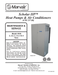
COMMERCIAL PRODUCT SERVICE MANUAL
CONCERNS:
• BLOWERS
• HEATING
• COOLING
COMMERCIAL PRODUCTS SERVICE MANUAL
AIRFLOW/BLOWER CONCERNS
BLOWER MOTOR INOPERATIVE
1. All speeds:
a. Check fuse under the hood by the battery.
b. If fuse is good, check for power through the relay. If no power at the relay, replace the fuse.
c. Check switch connections.
d. Check switch for 12 volts at corresponding terminals: L-low, M-medium, H-high. If no power, replace switch.
e. Check ground wire at rear unit; it must be tight and not corroded.
f. Check harness for power at rear connector plug: red-low, yellow-medium, orange-high. All should light a 12
volt test light. If not, check wiring harness for cuts, tears, burns, etc. Repair or replace as necessary.
g. If power is present at plug, replace blower motor.
2. One or more speeds inoperative: .
a. Check wire connections at switch.
b. Check switch for 12 volts at terminal of non-functioning speed: L-low, M-medium, H-high. If no power,
replace blower switch.
c. Check for power at rear connector. If no power is found on corresponding plug, check for shorts or burns
in wiring harness. If this is alright, replace blower motor.
MOST COMMON BLOWER PROBLEMS
1. Wires not on blower switch properly.
2. Poor ground.
3. Defective blower motor.
4. Burnt, cut or torn wiring.
BLOWER MOTOR NOISE
1. Blower wheels misaligned or broken.
2. Screw or other foreign object in blower housing or duct hose area.
3. Duct hose restricted behind sidewall.
COMMERCIAL PRODUCTS SERVICE MANUAL
HEATING CONCERNS
REAR UNIT DOES NOT HEAT, BUT DASH UNIT DOES HEAT
1. Locate the manual water valves and make sure they are open.
2. Check coolant levels
3. If unit still does not heat, check for kinks in heater hoses.
4. If heater hoses look all right, you must bleed air from rear system. This is done by crimping off OEM heater line before it
enters OEM heater core. Run vehicle on fast idle (1500 RPM) or at highway speeds to bleed air from system.
NEITHER REAR NOR FRONT UNITS HEAT
1. Check coolant levels.
2. Check thermostat for proper operation.
COMMON PROBLEMS
1. Dash selector switch is in wrong mode.
2. Air in system due to low coolant.
3. Low coolant.
4. Kinked heater hose.
5. Defective water valve.
6. Closed manual water valves.
COMMERCIAL PRODUCTS SERVICE MANUAL
COOLING CONCERNS CHECK LIST
Rear Unit Does Not Cool, But Dash Unit Does Cool:
1. Check condenser fans for proper operation.
2. If fans work properly, check refrigerant charge amount with gauges and appropriate charging chart.
3. If all of the above are good, replace the expansion valve and recharge the A/C system.
Neither Rear nor the Front Unit Cools:
1. Check clutch on compressor for proper engagement.
2. Check electrical system.
3. If these are all right, check refrigerant charge with gauges and charging chart.
4. If there is no charge, perform leak test. If leak is found, repair.
5. If the units still do not work, call ProAir.
Common Problems:
1. Loss of refrigerant (defective o-ring, fitting, or loose connection).
2. Defective compressor.
3. Stuck expansion valve.
4. Defective pressure switch..
COMMERCIAL PRODUCT SERVICE MANUAL
REPAIR PROCEDURES:
• REMOVE AND REPLACE HEAT COIL
• REMOVE AND REPLACE EVAPORATOR
• REMOVE AND REPLACE THERMOSTAT
• REMOVE AND REPLACE WATER VALVE
• REMOVE AND REPLACE BLOWER
COMMERCIAL PRODUCTS SERVICE MANUAL
REMOVE AND REPLACE INSTRUCTIONS
HEATER COILS
REMOVE:
1. Remove the screws and or clips holding the case top/cover in place.
2. Crimp off the hoses close to the heater.
3. Loosen the worm gear clamps and pull the hoses off the nipples.
4. If applicable, take out the screws holding the coil in place.
5. Remove the coil.
REPLACE:
1. Reverse the above procedure.
2. Tighten the worm gear clamps to 30 in/lb.
COMMERCIAL PRODUCTS SERVICE MANUAL
REMOVE AND REPLACE INSTRUCTIONS
EVAPORATOR COILS
REMOVE:
1. Connect a refrigerant recapturing / recycling machine to the vehicle service valves and recapture the refrigerant from the
system.
2. Remove the screws and/or clips holding the case front top bracket in place.
3. Remove the refrigerant tape around the coil fittings at the hose.
4. Disconnect the liquid line with 5/8” and 3/4” open end wrenches.
5. Disconnect the suction hose with 7/8” and 1 1/16” open end wrenches.
6. Remove the coil from the case bottom.
REPLACE:
1. Reverse the above procedure.
2. Torque the hose fittings according to the torque chart.
3. Recharge the system with oil and refrigerant according to current charging procedures.
COMMERCIAL PRODUCTS SERVICE MANUAL
REMOVE AND REPLACE INSTRUCTIONS
THERMAL EXPANSION VALVES
REMOVE:
1. Connect a refrigerant recapturing / recycling machine to the vehicle and evacuate the system.
2. Remove the refrigerant tape covering the valve and coil fitting.
3. Disconect the liquid line from the expansion valve with a 5/8" and 3/4" open end wrench.
4. Remove the bulb clamp from the coil suction tube.
5. Remove the expansion valve from the coil with 5/8"and 7/8" open end wrench.
REPLACE:
1. Reverse the above procedure.
2. Tighten the fittings to 12 ft/lb.
ORIENTATION OF BULB CLAMP ON
THE SUCTION TUBE IS CRITICAL.
PLACE BULB AT THE FOUR O’CLOCK
POSITION AS SHOWN.
4 O’CLOCK POSITION
END VIEW OF TUBE / CLAMP / BULB ORIENTATION
COMMERCIAL PRODUCTS SERVICE MANUAL
REMOVE AND REPLACE INSTRUCTIONS
WATER VALVES
REMOVE:
1. Loosen the radiator cap to relieve system pressure.
2. Crimp off the hoses on each side of the valve.
3. Loosen the worm gear clamps on each hose and pull the valve from the hoses.
REPLACE:
1. Reverse the above procedure.
2. Tighten the worm gear hose clamps to 30 in/lb.
ILLUSTRATED ABOVE IS THE CORRECT POSITIONING OF
THE HOSE ON THE NIPPLE AND THE WORM GEAR CLAMP.
COMMERCIAL PRODUCTS SERVICE MANUAL
REMOVE AND REPLACE INSTRUCTIONS
BLOWER ASSEMBLIES
REMOVE:
1. In most instances you will have to remove the unit cover first. Take out the screws holding the cover in place.
2. Disconnect the wire harness at the motor plug.
3. Unscrew the blower retainer bracket from the unit case.
4. Remove any other screws or bolts holding the blower assembly in place.
REPLACE:
Reverse the above procedure.
1.
WIRE CONNECTIONS @ BLOWER
CONDENSER FANS:
REMOVE:
1. Remove the fasteners holding the fan motors in place.
2. Disconnect the wire harness from the motor.
3. Remove the fan motor. Note motor orientation.
TYPICAL BLOWER ASSEMBLY
REPLACE
1. Reverse the above procedure.
CONDENSER WITH ONE FAN REMOVED
COMMERCIAL PRODUCT SERVICE MANUAL
PARTS BY UNIT LINE:
• CONDENSERS
• HEATERS
• COMBINATION UNITS
COMMERCIAL PRODUCT SERVICE MANUAL
CONDENSERS:
• 104 CONDENSER PARTS
• 105 CONDENSER PARTS
• 106 CONDENSER PARTS
COMMERCIAL PRODUCTS SERVICE MANUAL
104 CONDENSER, PART NUMBER 60 000 699
1
2
3
6
4
5
1
03 000 034
Coil, condenser
2
3
06 000 099
11 000 076
Mounting bracket
4
60 000 397
05 000 099
5
6
7
8
9
Fan, 16"
Hose assembly
Drier bottle
01 000 070
02 000 110
Switch, high-low pressure
Pull tie kit
06 000 144
Dryer bottle bracket
02 000 097
Fan mounting bracket
COMMERCIAL PRODUCTS SERVICE MANUAL
frigiking SS 105 CONDENSER, PART NUMBER 50 000 590
2
1
3
7
6
5
4
1
03 000 025
Coil, condenser
2
Mounting bracket
3
06 000 336
11 000 147
4
5
60 000 398
05 000 099
6
01 000 070
7
06 000 335
Fan, 11" puller, water proof
Hose assembly
Drier bottle
Switch, high-low pressure
Mounting bracket, dryer bottle, stainless steel
COMMERCIAL PRODUCTS SERVICE MANUAL
106 ROOF-TOP CONDENSER, PART NUMBER 31 000 011
2
1
5
4
3
1
03 000 076
Coil, condenser
2
3
11 000 127
05 000 284
Fan, 11" puller
Right side tube assembly
4
05 000 283
06 000 319
Left side tube assembly
Mounting bracket
5
6
7
COMMERCIAL PRODUCT SERVICE MANUAL
HEATERS:
•
•
•
•
•
•
•
•
•
•
•
•
•
•
•
50M BTU DASH HEATER
418 HEATER PARTS
420 HEATER PARTS
425 HEATER PARTS
432 HEATER PARTS
450 HEATER
455 HEATER PARTS
460 HEATER
UNDERSEAT HEATER PARTS
901 HEATER PARTS
435/445 HEATER PARTS
465/475 HEATER PARTS
435 HEATER PARTS (STEEL)
465 HEATER PARTS (STEEL)
80VDC HEATER
!"##$%!&'()*%"+,!-.).$%/&!$)#'0,'(
FRIGKING, 50M BTU DASH H/O, FREEBLOW 24V
FRIGIKING, 50M BTU DASH H/O DUCTED 24V
FRIGIKING, 50M BTU DASH H/O 24V DUCTED 4-2 ½” HA
2
PART NO. 66 000 110
PART NO. 66 000 111
PART NO. 66 000 112
1
8&9
7
3
4
1
2
3
4
5
6
7
8
9
PART NUMBER
11 000 141
01 000 073
06 000 414
01 000 230
01 000 027
06 000 412
06 000 411
03 000 104
08 000 001
5
6
DESCRIPTION
Blwr assy, Spal 24v dbl small
Harn, SPAL blower motor
Top, ducted 4-2 ½” outlets dash (P/N 66 000 112)
Harn, 50m btu dash htr
Switch, 4-position rotary
Top, ducted dash heater (P/N 66 000 111)
Top, free blow dash heater (P/N 66 000 110)
Coil, heater 50m btu
Foam, 1/8 x 4 x 5.66ft
F:\Engine\CommProdServManual2002\50mbtudashh-o.doc
!"##$%!&'()*%"+,!-.).$%/&!$)#'0,'(
418 HEATER 18m BTU, 12v
418 HEATER 18m BTU, 24v
1
1
2
PART NUMBER
03 000 092
11 000 142
11 000 143
P/N 66 000 090
P/N 66 000 091
2
DESCRIPTION
Coil, ht 18m BTU 418 htr
Fan, SPAL 12v 6.5” pusher (Ref. P/N 66 000 090)
Fan, SPAL , 24v 6.5” pusher (Ref. P/N 66 000 091)
\\PROAIR\SYS\Engine\CommProdServManual2002\418heaters.doc
COMMERCIAL PRODUCT SERVICE MANUAL
420 HEATER, PART NUMBER 50 000 111
1
2
6
4
5
8
7
06 000 049
03 000 020
Case, coil mounting
3
4
5
11 000 098
Motor, 12v 2-speed
11 000 044
06 000 050
Fan, 6” 4-blade
6
7
06 000 053
06 000 224
Fan guard
8
06 000 225
Motor bracket
1
2
Coil, heat
Panel, fan mounting
Mounting bracket
3
COMMERCIAL PRODUCTS SERVICE MANUAL
425 HEATER, PART NUMBER 66 000 061
1
2
5
3
4
1
06 000 328
Case top
2
3
03 000 079
06 000 330
Coil, heater
4
01 000 091
Case bottom
Resistor
5
6
11 000 074
01 000 087
Blower assembly
Wire harness
7
COMMERCIAL PRODUCTS SERVICE MANUAL
432 HEATER, PART NUMBER 66 000 078
1
8
2
3
7
4
6
5
1
06 000 258
Case bottom
2
3
11 000 126
03 000 057
Fan, 7" blade
Coil, heater
4
06 000 259
11 000 098
Case top
5
6
7
8
Motor, 12v
01 000 001
01 000 086
Switch, 3-position
06 000 261
Mounting bracket
Knob, w/set screw
!"##$%!&'()*%"+,!-.).$%/&!$)#'0,'(
450 HEATER 50M BTU UPRIGHT
450 HEATER 50M BTU UPRIGHT W/OPT WIRING
PART NO. 66 000 084
PART NO. 66 000 086
1
2
1
2
PART NUMBER
03 000 088
11 000 138
DESCRIPTION
Coil, heat 50m BTU 450
Blower Assembly, 12v wire wnd 2-wheel
F:\Engine\CommProdServManual2002\450heaters.doc
COMMERCIAL PRODUCTS SERVICE MANUAL
455 HEATER, PART NUMBER 50 000 115
1
2
3
4
5
1
06 000 087
Case top
2
3
11 000 068
03 000 030
Blower assembly
Coil, heater
4
06 000 088
5
6
06 000 044
01 000 071
Housing
Mounting bracket
7
Wiring harness
!"##$%!&'()*%"+,!-.).$%/&!$)#'0,'(
460 HEATER 60M BTU UPRIGHT
PART NO. 66 000 085
2
1
3
1
2
3
PART NUMBER
11 000 138
03 000 089
08 000 001
DESCRIPTION
Blower Assembly, 12v wire wnd 2-whl
Coil, Heat 60m BTU 460 BTU
Foam 1/8 x 4” x 3’
F:\Engine\CommProdServManual2002\460heater.doc
COMMERCIAL PRODUCTS SERVICE MANUAL
UNDERSEAT HEATER, PART NUMBER 50 000 494
1
2
3
4
5
1
01 000 091
Resistor
2
3
11 000 120
06 000 309
Fan, 9”
Housing
4
03 000 068
06 000 310
Coil
5
6
7
01 000 087
Mounting bracket
Wiring harness
COMMERCIAL PRODUCTS SERVICE MANUAL
901 HEATER, PART NUMBER 66 000 018
1
2
3
6
5
1
07 000 132
Case top
2
3
4
11 000 005
11 000 004
Blower motor
Blower wheel
07 000 026
Nose, 4-hole
5
07 000 133
Case bottom
6
03 000 015
Coil, heat only
4
COMMERCIAL PRODUCTS SERVICE MANUAL
435 HEATER, PART NUMBER 66 000 066, 445 HEATER 66 000 067
1
2
3
8
4
9
5
6
7
1
07 000 413
Case top
2
3
07 000 416
03 000 072
End cap, tube end
Coil, heater, 435,
4
11 000 126
5
6
11 000 098
Fan, 7" blade
Motor, 12v
07 000 412
Case bottom
7
8
9
06 000 325
07 000 415
Mounting bracket
02 000 122
End cap, blank
Clip, housing
03 000 073 Coil, heater 445,
COMMERCIAL PRODUCTS SERVICE MANUAL
465 HEATER, PART NUMBER 60 000 068, 475 HEATER 66 000 069
1
2
3
9
4
5
6
10
8
7
1
07 000 413
Case top
2
07 000 417
Center housing
3
4
07 000 416
03 000 074
11 000 126
End cap, tube end
Coil, heater 465, 03 000 075 Coil, heater 475
5
6
Fan, 7" blade
Case bottom
7
07 000 412
06 000 325
8
11 000 098
Motor, 12 v
9
07 000 415
10
02 000 122
End cap, blank
Clip, housing
Mounting bracket
COMMERCIAL PRODUCTS SERVICE MANUAL
435 HEATER, STEEL CASE, PART NUMBER 50 000 113
1
2
3
4
8
5
6
7
1
06 000 170
Case top
2
3
03 000 022
06 000 171
Coil
4
11 000 107
Fan blade, 7”
5
11 000 098
6
7
06 000 172
06 000 169
Motor, 12v
Case bottom
8
06 000 225
Housing
Leg, mounting
Motor mounting bracket
COMMERCIAL PRODUCTS SERVICE MANUAL
465 HEATER, STEEL CASE, PART NUMBER 50 000 116
1
2
3
4
5
6
8
1
06 000 173
Case top
2
3
03 000 023
06 000 175
Coil
Housing
4
11 000 107
5
6
11 000 098
06 000 174
Fan blade
Motor 12v
7
8
06 000 169
06 000 225
Case mounting
Leg. mounting
Motor mounting bracket
7
!"##$%!&'()*%"+,!-.).$%/&!$)#'0,'(
80VDC HEATER
PART NUMBER 66 000 094
1
2
1
2
PART NUMBER
03 000 093
11 000 146
DESCRIPTION
Element, 80v dc 1600 w
Blwr assy, Spal 12v sngl small
F:\Engine\CommProdServManual2002\66000094-80v.doc
COMMERCIAL PRODUCT SERVICE MANUAL
COMBINATION UNITS:
•
•
•
•
•
•
•
•
•
•
•
•
•
•
•
•
110/12V PARTS
526/552 PARTS
626 HEAT/COOL
921 HEAT/COOL
925 COOL ONLY PARTS
931 HEAT/COOL
935 HEAT/COOL PARTS
940/941 HEAT/COOL
960 HEAT/COOL PARTS
DASH MOUNT, HEAT ONLY
DASH MOUNT, A/C HEAT PARTS
CONTROL HEADS, CABLES,VACUUM
HARNESSES
CONTENDER PARTS
FMC DASH
LOT VEHICLE PARTS
SOLO PARTS
!"##$%!&'()*%"+,!-.).$%/&!$)#'0,'(
FRIGIKING, POWER PAK-310, 110/12V H/C
FRIGIKING, POWER PAK-310, 110/12V H/C ROOF MT
PART NO. 66 000 108
PART NO. 66 000 109
10
1
6
2
7
3
8
4
9
5
1
2
3
4
5
6
7
8
9
10
PART NUMBER
05 000 336
03 000 045
03 000 103
01 000 223
01 000 048
68 000 024
08 000 001
03 000 097
68 000 006
07 000 440
DESCRIPTION
Valve, Expan R-22
Coil, heat/cool 940/935
Coil, A/C 110/12v
Harness, Evaporator heat/blower
Thermostat, non-adjustable
Kit, Expansion block valve 2 ton
Foam, 1/8 x 4 x 3ft
Element, heat
Blower Assembly, SPAL double w/seals
Pan, Drain 110/12v
F:\Engine\CommProdServManual2002\110-12v.doc
COMMERCIAL PRODUCTS SERVICE MANUAL
526 COOL ONLY- PM MTR, PART NUMBER 66 000 117
552 HEAT COOL-PM MTR, PART NUMBER 66 000 118
1
7
6
2
3
5
1
2
3
4
60 001 157
Case bottom, heat/cool
60 001 158
03 000 003
Case bottom, cool only
Coil, heat/cool
03 000 004
Coil, cool only
Base, 526/552
Blower motor assembly
4
06 000 054
5
11 000 156
6
7
11 000 023
Louver
05 000 022
Thermal expansion valve
!"##$%!&'()*%"+,!-.).$%/&!$)#'0,'(
FRIGIKING 626 H/C UNIT
PART NO. 66 000 101
2
1
3
4
5
1
2
3
4
5
PART NUMBER
01 000 091
68 000 005
08 000 001
03 000 100
68 000 024
DESCRIPTION
Resistor, Blower AT, MM, VPSI
Motor Blower Assembly AT
Foam 1/8 x 4” x 3’
Coil, 626 H/C
Kit, Expansion Block Valve 2ton
F:\Engine\CommProdServManual2002\66000101-626.doc
!"##$%!&'()*%"+,!-.).$%/&!$)#'0,'(
921 FRIGIKING POWER PAK H/C
PART NUMBER 66 000 104
1
7
2
3
4
1
2
3
4
5
6
7
PART NUMBER
03 000 102
01 000 071
68 000 006
68 000 024
07 000 443
06 000 395
01 000 048
5
6
DESCRIPTION
Coil, ht/cool 921
Harness 960 SPAL blower
Blower Assembly w/seals
Kit, Expansion Block valve 2ton
Pan, Drain 921
Plate, 921 Blower divider
Thermostat, non-adjustable
F:\Engine\CommProdServManual\66000104-921.doc
COMMERCIAL PRODUCTS SERVICE MANUAL
925 COOL ONLY, PART NUMBER 60 000 552
1
2
3
4
7
8
6
5
1
06 000 032
Case top
2
01 000 048
Thermostat, non-adjustable
3
4
05 000 022
11 000 008
Thermal expansion valve
Louver
5
06 000 035
Case front
6
06 000 031
Housing
7
8
11 000 138
03 000 014
Blower motor assembly
Coil
!"##$%!&'()*%"+,!-.).$%/&!$)#'0,'(
931 FRIGIKING POWER PAK H/C
PART NUMBER 66 000 105
5
1
6
2
7
3
4
1
2
3
4
5
6
7
PART NUMBER
03 000 101
01 000 071
68 000 006
07 000 442
68 000 024
06 000 393
01 000 048
DESCRIPTION
Coil, Heat/Cool 931
Harness, 960 SPAL blower
Double Blower Assembly w/seals
Drain Pan
Kit, Expansion Block valve 2ton
Plate, 931 blower divider
Thermostat, non-adjustable
F:\Engine\CommProdServManual\66000105-931.doc
!"##$%!&'()*%"+,!-.).$%/&!$)#'0,'(
935 UNITS
5
5
6
P/N 66 000 087 frigiking, 935 h/c roof mt
P/N 66 000 046 Power Pak, 99-935 vert
1
5
6
2
3
4
P/N 66 000 004 frigiking, power pak 98-935 h/c
1
2
3
4
5
6
PART NUMBER
68 000 006
03 000 045
68 000 024
07 000 338
01 000 206
01 000 073
01 000 071
01 000 048
DESCRIPTION
Blower Assembly, SPAL double w/seals
Coil, Heat/Cool
Valve, expansion block R-134a 2 ton
Pan, drain roto cast
Harness, wire (P/N 66 000 087)
Harness SPAL Blower motor (P/N 66 000 004)
Harness, 960 blower (P/N 66 000 046)
Thermostat, non adjustable w/12” cap tube
F:\Engine\CommProdServManual2002\935.doc
!"##$%!&'()*%"+,!-.).$%/&!$)#'0,'(
940 FRIGIKING POWER PAK H/C
941 FRIGIKING POWER PAK H/C
PART NUMBER 66 000 008
PART NUMBER 66 000 106
1
6
2
3
1
2
3
4
5
6
PART NUMBER
03 000 045
68 000 006
68 000 024
07 000 441
01 000 048
06 000 152
4
5
DESCRIPTION
Coil, Heat/Cool 935/940
Double Blower Assembly w/seals
Kit, Expansion BLock valve 2ton
Pan, drain 941 or Pan, drain 940
Thermostat, non-adjustable
Plate, blower divider 940 h/c
F:\Engine\CommProdServManual2002\940-941.doc
!"##$%!&'()*%"+,!-.).$%/&!$)#'0,'(
FRIGIKING 960 H/C WITH 4-HOLE OUTLET
FRIGIKING 960 H/C DASH UNIT
PART NUMBER 66 000 107
PART NUMBER 60 000 494
1
7
8
2
3
4
9
5
6
1
2
3
4
5
6
7
8
9
PART NUMBER
04 000 039
01 000 071
03 000 027
03 000 026
68 000 006
68 000 024
06 000 138
01 000 048
11 000 024
DESCRIPTION
Vac harn, dual solenoid-960
Harness, 960 SPAL Blower
Coil, 960 heat
Coil, 960 A/C
Double Blower Assembly w/seals
Kit, Expansion Block valve 2ton
Panel, case front 960 h/c
Thermostat non-adj
Solenoid, vac
F:\Engine\CommProdServManual2002\960UNITS.doc
COMMERCIAL PRODUCTS SERVICE MANUAL
DASH MOUNTED HEAT ONLY, PART NUMBER 66 000 034
1
2
3
4
5
1
06 000 294
Case top
2
3
06 000 187
11 000 112
Case bottom
Blower motor assembly
4
03 000 064
5
6
06 000 285
Coil, heat only
Case front
7
COMMERCIAL PRODUCTS SERVICE MANUAL
DASH MOUNTED A/C, HEAT, DEFROST PART NUMBER 66 000 032
1
2
3
4
1
11 000 068
Blower assembly
2
3
03 000 049
03 000 048
01 000 048
08 000 041
Coil, heat
Coil, evaporator
4
5
6
7
Thermostat, non-adjustable
Blower seal
COMMERCIAL PRODUCTS SERVICE MANUAL
CONTROL HEADS, CABLES, AND VACUUM HARNESSES
67 000 012 CONTROL HEAD, 960
67 000 006 CONTROL HEAD
67 000 005 CONTROL HEAD
02 000 171 CABLE,
02 000 178 CABLE,
02 000 172 CABLE
04 000 039 VACUUM HARNESS, 960
11 000 024 SOLENOID VALVE
01 000 084 LIGHT BULB,
CONTROL HEAD
!"##$%!&'()*%"+,!-.).$%/&!$)#'0,'(
FRIGIKING CONTENDER POWER PAK
PART NUMBER 66 000 033
1
2
3
7
4
5
1
2
3
4
5
6
7
PART NUMBER
03 000 062
03 000 063
01 000 154
68 000 006
07 000 345
68 000 024
01 000 048
6
DESCRIPTION
Coil, Heat Contender
Coil, Evaporator Contender
Harness, wire SPAL Blower Step Van
Blower Assembly, Double 12v w/seals
Pan, Drain Step Van
Kit, Expansion Block valve 2ton
Thermostat, non-adjsutable
F:\Engine\CommProdServManual2002\66000033Contender.doc
!"##$%!&'()*%"+,!-.).$%/&!$)#'0,'(
FRIGIKING POWER PAK, FMC DASH H/O
PART NUMBER 66 000 089
1
4
2
3
1
2
3
4
PART NUMBER
01 000 154
03 000 090
11 000 141
11 000 047
DESCRIPTION
Harness, wire SPAL Blower
Coil, heat 42m BTU FMC
Blower Assembly, SPAL 24v dbl small
Louver, red, euro 2”
J:\Engine\CommProdServManual2002\FMCdash-ho.doc
!"##$%!&'()*%"+,!-.).$%/&!$)#'0,'(
CAPACITY FRIGIKING LOT
VEHICLES
12V H/O
12V H/C
24V H/O
24V H/C
PART NUMBER 66 000 095
PART NUMBER 66 000 096
PART NUMBER 66 000 097
PART NUMBER 66 000 098
4
6
7
2
8
3
1
1
2
3
4
5
6
7
8
9
PART NUMBER
03 000 095
01 000 210
68 000 006 OR
68 000 009
03 000 096
07 000 439
68 000 024
06 000 373
01 000 048
11 000 097
5
DESCRIPTION
Coil, A/C Lot Vehicle
Harness SPAL Blower Capacity
Blower Assembly, Double 12v w/seals (Ref: P/Ns 66 000 095 &
66 000 096)
Blower Assembly, Double 24v w/ seals (Ref: P/Ns 66 000 097 &
66 000 098)
Coil, heat only Lot Vehicle
Pan, drain Lot Vehicle
Kit, Expansion Block valve 2ton
Cover, Coil Access
Thermostat, non-adjustable
Louver, rectangular screw-in
-For hose assembly information refer to the following pages.9
F:\Engine\CommProdServManual\LotVehicles.doc
!"##$%!&'()*%"+,!-.).$%/&!$)#'0,'(
CAPACITY FRIGIKING LOT VEHICLE HOSE ASSEMBLIES
(INCLUDED WITH STANDARD KIT)
2
3
1
4
5
1
2
3
4
5
6
7
8
PART NUMBER
62 000 269
62 000 267
62 000 268
62 000 270
01 000 211
05 000 351
01 000 027 AND/OR
01 000 024
01 000 212
6
7
8
DESCRIPTION
Hose assembly, 5/16 refrig x 2.33ft
Hose assembly, ½ refrig x 2.33ft
Hose assembly, 5/16 refrig x 4.58ft
Hose assembly, 5/16 x 1.58ft
Switch, lo-pressure
Valve, water push pull to off
4 position rotary switch AND/OR
2 position rotary switch
Switch, high-pressure
-Hose assemblies continued on next page.F:\Engine\CommProdServManual\LotVehicles.doc
!"##$%!&'()*%"+,!-.).$%/&!$)#'0,'(
CAPACITY FRIGIKING LOT VEHICLE HOSE ASSEMBLIES
(OPTIONAL)
1
2
3
4
1
2
3
4
PART NUMBER
62 000 289
62 000 290
62 000 291
62 000 292
DESCRIPTION
Hose Assembly, ½ Refrig x 6.67
Hose Assembly, 13/32 Refrig x 4.34
Hose Assembly, ½ Refrig x 8.00
Hose Assembly, 13/32 Refrig x 5.75
!"##$%!&'()*%"+,!-.).$%/&!$)#'0,'(
FRIGIKING SOLO HEAT ONLY 24V
FRIGIKING SOLO HEAT ONLY BRUSHLESS
FRIGIKING SOLO HEAT ONLY 12V
PART NO. 66 000 034
PART NO. 66 000 039
PART NO. 66 000 045
1
2
3
1
2
3
PART NUMBER
03 000 064
01 000 154
68 000 009
68 000 010
68 000 006
(BRUSHLESS)
DESCRIPTION
Coil, heat Solo
Harn, wire SPAL blwr step van
Double Blower Assembly 24v w/seals (Ref: 66 000 034)
Double Blower Assembly, 24v brushless (Ref: 66 000 039)
Double Blower Assembly w/seals (Ref: 66 000 045)
F:\Engine\CommProdServManual2002\SoloUnits.doc
COMMERCIAL PRODUCT SERVICE MANUAL
SCHEMATICS:
• WIRING
• WATER PLUMBING
• A/C PLUMBING
• VACUUM
COMMERCIAL PRODUCT SERVICE MANUAL
WIRING SCHEMATICS:
•
•
•
•
•
•
•
•
•
•
•
•
•
110/12V H/C 40 000 155
420/435 STEEL HEATER 40 000 124
455 MOTOR 40 000 148
435/445/465 STEEL HTR 40 000 120
435/445/465/475 PLAS HTR 40 000 122
526/552 40 000 104
935 40 000 168
935/105 HOT WEATHER 40 000 169
935/106 HOT WEATHER 40 000 170
960 40 000 106
BOOSTER PUMP 40 000 177
FORD O.E.M W/(4) POS SW 40 000 153
UNDERSEAT HEATER 40 000 123
NOTES:
NOTES:
!
NOTES:
NOTES:
!
NOTES:
PLASTIC
PLASTIC
PLASTIC
!
NOTE:
NOTES:
NOTES:
NOTES:
5) HARNESS - 125° INSULATED WIRE
EQUIVALENT TO SAE SPECIFICATION
J1128 TYPE SXL
6) OTHER SYSTEM CONSULT FACTORY
!
NOTES:
NOTES:
NOTES:
!
COMMERCIAL PRODUCT SERVICE MANUAL
WATER PLUMBING SCHEMATICS:
•
•
•
•
BOOSTER PUMP - 40 000 167
DASH & STANDARD HEATER 40 000 172
BUS DASH & AUX HTR 40 00 154
BUS DASH CNTRLD, STEP & AUX HTR DASH
40 000 151
• BUS DASH, STEP & (2) AUX HTR 40 000 150
• BUS DASH, STEP & AUX HTR 40 000 149
NOTE:
COMMERCIAL PRODUCT SERVICE MANUAL
A/C PLUMBING SCHEMATICS:
•
•
•
•
•
•
•
•
110/12V H/C-106 - 40 000 165
110/12V H/C - 40 000 166
925/935/940 E SERIES PRECHRGD 40 000 173
925/935/940 STANDARD 40 000 174
935/940 - 105 HOT WEATHER 40 000 171
935/940 - 106 HOT WEATHER 40 000 147
935/940 - 106 HT WTHR FRTLNR 40 000 185
BUS CMPRSSR AUX/REAR UNIT 40 000 152
COMMERCIAL PRODUCT SERVICE MANUAL
VACUUM SCHEMATICS:
• 960 VACUUM - 40 000 119
!
COMMERCIAL PRODUCT SERVICE MANUAL
MISCELLANEOUS
SPECIFICATIONS:
• REFRIGERANT CHARGE AMOUNTS
• WIRE SIZING TABLE
• TORQUE SPECIFICATIONS
COMMERCIAL PRODUCTS SERVICE MANUAL
REFRIGERANT CHARGE AMOUNTS
925 W/14’ OF HOSES (A/C - 1/2”, 5/16”)
12oz. R-134a
3oz. OIL
935 W/14’ OF HOSES (A/C - 1/2”, 5/16”)
16oz. R-134a
4oz. OIL
960 W/RADIATOR CONDENSER
2.125lbs
6oz. OIL
960 W/105 SKIRT CONDENSER (15’ LIQUID LINE)
1.125lbs
4oz. OIL
960 TIE - IN
**CONSULT PROAIR**
105/106 CONDENSOR ADDED TO SYSTEM (A/C 13/32”, 5/16”) ADD 16oz R-134a, AND 3oz OF OIL TO
925/935 AMOUNTS.
NOTE: FOR EACH ADDITIONAL 10’ OF LIQUID LINE ADD 3oz OF R-134a, AND .75oz OIL.
LIQUID LINES LONGER THAN 25’ YOU MUST CONSULT THE FACTORY FOR CHARGE AMOUNTS.
DIFFERENT SIZE (DIAMETER) HOSES, CONSULT FACTORY FOR CHARGE AMOUNTS.
CAUTION: USE ONLY THE EXACT OIL SPECIFIED BY THE COMPRESSOR MANUFACTURER. USE
OF OILS OTHER THAN THOSE SPECIFIED WILL VOID THE WARRANTY!
COMMERCIAL PRODUCTS SERVICE MANUAL
CONDUCTOR SIZING TABLE, MAXIMUM 10% VOLTAGE DROP @ 12VDC
GAUGE
SIZE
METRIC
ENG.
CURRENT DRAW IN AMPERES
1
2
3
4
5
6
7
8
9
10
15
20
25
30
40
50
60
70
80
100
MAX LENGTH OF SAEJ 1128 CONDUCTOR (in feet) FROM POWER SOURCE TO DEVICE.
.5mm
20
107
53
36
27
21
18
15
13
12
11
7
.8mm
18
172
86
57
43
34
29
25
21
19
17
11
9
1.0mm
16
261
130
87
65
52
43
37
33
29
26
17
13
10
2.0mm
14
413
207
138
103
83
69
59
52
46
41
28
21
17
14
3.0mm
12
651
326
217
163
130
109
91
81
72
65
43
33
26
22
16
5.0mm
10
1043
521
348
261
208
174
149
130
116
104
70
52
42
35
26
8.0mm
8
1653
827
551
413
331
276
236
13.0mm
6
2892
1446
954
723
578
482
413
19.0mm
4
4170
2085 1390
1043
834
695
596
207
21
17
184
165
110
83
66
55
41
33
28
24
21
362
321
289
193
145
116
96
72
58
48
41
36
29
521
463
417
278
209
167
139
104
60
52
42
83
70
COMMERCIAL PRODUCTS SERVICE MANUAL
TORQUE SPECIFICATIONS, REFRIGERANT LINE FITTINGS
TUBE O.D.
THREAD SIZE
FITTING SIZE
FT/LB
STANDARD
METRIC
6 +/- 1
1/4"
7/16"
4
M-14
12 +/- 1
3/8"
5/8"
6
M-16/M-18
18 +/- 2
1/2"
3/4"
8
M-20/M-22
24 +/- 3
5/8"
7/8"
10
M-24
31 +/- 2
3/4"
1 1/16"
12
M-27
30 +/- 3
1" - 14
FTO
N/A
30 +/- 3