1
R
Transport Air Conditioning
R
2P
BLK
1
BRN
WHT
BLU
2
GRN/YEL
WHT
C
EVAP.
RED RED
WHT
F
H
BLU
R
1
2
YEL
C
S
BLU
PTC
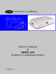
SERVICE MANUAL
for
MODEL AirV
Rooftop Air Conditioning Systems
T--298 Rev G
SERVICE MANUAL
For
AirV
AIR CONDITIONING AND
HEATING EQUIPMENT
MODELS
68RV11112A
68RV11122A
68RV11302A
68RV14102A
68RV14103A
68RV14113A
68RV14123A
68RV15102A
68RV15103A
SAFETY SUMMARY
GENERAL SAFETY NOTICES
The following general safety notices supplement the specific warnings and cautions appearing elsewhere in
this manual. They are recommended precautions that must be understood and applied during operation and
maintenance of the equipment covered herein. The general safety notices are presented in the following three
sections labeled: First Aid, Operating Precautions and Maintenance Precautions. A listing of the specific
warnings and cautions appearing elsewhere in the manual follows the general safety notices.
FIRST AID
An injury, no matter how slight, should never go unattended. Always obtain first aid or medical attention
immediately.
OPERATING PRECAUTIONS
Always wear safety glasses.
Keep hands clear of the evaporator blower and condenser fan.
No work should be performed on the unit until all circuit breakers and start--stop switches are turned off, and
power supply is disconnected.
Always work in pairs. Never work alone.
In case of severe vibration or unusual noise, stop the unit and investigate.
MAINTENANCE PRECAUTIONS
Beware of unannounced starting of the evaporator blower & condenser fan. Do not remove the ceiling grill
assembly or the upper unit cover assembly before turning the power off, and disconnecting the power supply.
Before disconnecting, discharge capacitors by shorting across the capacitors terminals. (See Paragraph
3.6.8)
When disassembling wiring, use numbered stickers to identify wire leads and terminals. This aids in quick,
accurate reassembly.
Be sure power is turned off before working on motors, controllers, or electrical control switches. Tag any circuit
breakers and power supply to prevent accidental energizing of circuits.
Do not bypass any electrical safety devices, e.g. bridging an overload, or using any sort of jumper wires.
Problems with the system should be diagnosed and any necessary repairs must be performed by qualified
service personnel.
In case of electrical fire, open circuit switch and extinguish with CO2 (never use water).
Use dry nitrogen to pressurize the system for leak checking. Be careful not to exceed 150 psig test pressure in
the hermetic compressor.
Coil fins are sharp. Use care when removing the cover form the base pan to avoid personal injury.
Oil vapor in piping stubs can ignite from torch flame and cause serious injury. Exercise extreme care when
brazing, and keep brazing cloth and fire extinguisher handy for emergency use.
Disconnect power to the AirV unit before checking the capacitor.
10/09
Safety-- i
T-298
SPECIFIC WARNING AND CAUTION STATEMENTS
The statements listed below are applicable to the refrigeration unit and appear elsewhere in this manual.
These recommended precautions must be understood and applied during operation and maintenance of the
equipment covered herein.
SPECIFIC WARNINGS AND CAUTIONS
WARNING
Be sure to observe warnings listed in the safety summary in the front of this manual before
performing maintenance on the AirV system
WARNING
Before working on the unit be sure to first disconnect all electric power to the unit to avoid the
possibility of electrical shock and personal injury. Before disconnecting, discharge capacitors by shorting across the capacitors terminals (Refer to paragraph 3.6.8)
WARNING
Shield coils with cardboard to protect hands against injury from sharp metal edges when removing compressor and other components.
WARNING
Oil vapor in piping stubs can ignite from torch flame and cause serious injury. Exercise extreme care when brazing, and keep brazing cloth and fire extinguisher handy for emergency
use.
WARNING
Disconnect power to the AirV unit before checking the capacitor.
WARNING
Do not touch the metal of the screwdriver when discharging the capacitor. You could receive
a shock.
WARNING
Before installing thermostat, turn off all power to unit. There may be more than one power
disconnect. Electrical shock can cause personal injury or death.
CAUTION
In order for the AirV systems to operate efficiently, a dedicated 115 Volt 20 Amp power connection is required.
T--298
Safety-- ii
10/09
CAUTION
Do not use carbon tetrachloride, solvents, or waxes containing solvents to clean plastic sections.
CAUTION
Coil fins are sharp. Use care when removing the cover form the base pan to avoid personal
injury.
CAUTION
The change from Fahrenheit to Celsius will be permanent. It cannot be changed back to Fahrenheit.
CAUTION
When re--assembling, ensure the battery springs are correctly placed in the battery spring
holders.
CAUTION
Improper wiring or installation may damage thermostat. Wiring must conform to local and
national electrical codes.
10/09
Safety-- iii
T-298
TABLE OF CONTENTS
PARAGRAPH NUMBER
Page
SPECIFIC WARNING AND CAUTION STATEMENTS . . . . . . . . . . . . . . . . . . . . . . . . . . . . . . . . . . . . . . . . . . .
ii
SPECIFIC WARNINGS AND CAUTIONS . . . . . . . . . . . . . . . . . . . . . . . . . . . . . . . . . . . . . . . . . . . . . . . . . . . . . .
ii
DESCRIPTION . . . . . . . . . . . . . . . . . . . . . . . . . . . . . . . . . . . . . . . . . . . . . . . . . . . . . . . . . . . . . . . . . . . . . . . . . . . . . . .
1--1
1.1 INTRODUCTION . . . . . . . . . . . . . . . . . . . . . . . . . . . . . . . . . . . . . . . . . . . . . . . . . . . . . . . . . . . . . . . . . . . . .
1--1
1.2 SERIAL NUMBER IDENTIFICATION . . . . . . . . . . . . . . . . . . . . . . . . . . . . . . . . . . . . . . . . . . . . . . . . . . . .
1--1
1.3 DESIGN CHANGE DESCRIPTIONS . . . . . . . . . . . . . . . . . . . . . . . . . . . . . . . . . . . . . . . . . . . . . . . . . . . .
1--1
1.4 SYSTEM (UNIT) INSTALLED DIMENSIONS . . . . . . . . . . . . . . . . . . . . . . . . . . . . . . . . . . . . . . . . . . . . .
1--9
1.5 SERIAL NUMBER LOCATIONS . . . . . . . . . . . . . . . . . . . . . . . . . . . . . . . . . . . . . . . . . . . . . . . . . . . . . . . . 1--14
1.6 AirV SYSTEM COMPONENT SPECIFICATIONS . . . . . . . . . . . . . . . . . . . . . . . . . . . . . . . . . . . . . . . . . 1--15
1.6.1 Refrigerant Charge . . . . . . . . . . . . . . . . . . . . . . . . . . . . . . . . . . . . . . . . . . . . . . . . . . . . . . . . . . . . . . . . 1--15
1.6.2 Compressor -- 115 Volts, 60 Cycles, 1 Phase . . . . . . . . . . . . . . . . . . . . . . . . . . . . . . . . . . . . . . . . . 1--15
1.6.3 Compressor -- 220 Volts, 50 Cycles, 1 Phase . . . . . . . . . . . . . . . . . . . . . . . . . . . . . . . . . . . . . . . . . 1--15
1.6.4 Thermostat Range (All Free Blow Units) . . . . . . . . . . . . . . . . . . . . . . . . . . . . . . . . . . . . . . . . . . . . . . 1--15
1.6.5 Return Air Sensor (Thermistor) . . . . . . . . . . . . . . . . . . . . . . . . . . . . . . . . . . . . . . . . . . . . . . . . . . . . . . 1--15
1.6.6 Heat Pump Sensors (Thermistors) . . . . . . . . . . . . . . . . . . . . . . . . . . . . . . . . . . . . . . . . . . . . . . . . . . . 1--15
1.7 START--UP . . . . . . . . . . . . . . . . . . . . . . . . . . . . . . . . . . . . . . . . . . . . . . . . . . . . . . . . . . . . . . . . . . . . . . . . . . 1--15
1.8 Dry Mode Function . . . . . . . . . . . . . . . . . . . . . . . . . . . . . . . . . . . . . . . . . . . . . . . . . . . . . . . . . . . . . . . . . . . . 1--15
1.9 REFRIGERANT CYCLE--STANDARD SYSTEM . . . . . . . . . . . . . . . . . . . . . . . . . . . . . . . . . . . . . . . . . . 1--15
1.10 REFRIGERANT CYCLE -- HEAT PUMP . . . . . . . . . . . . . . . . . . . . . . . . . . . . . . . . . . . . . . . . . . . . . . . . . 1--16
1.10.1 Cooling . . . . . . . . . . . . . . . . . . . . . . . . . . . . . . . . . . . . . . . . . . . . . . . . . . . . . . . . . . . . . . . . . . . . . . . . . . 1--16
1.10.2 Heating . . . . . . . . . . . . . . . . . . . . . . . . . . . . . . . . . . . . . . . . . . . . . . . . . . . . . . . . . . . . . . . . . . . . . . . . . . 1--17
1.11 FREQUENTLY ASKED QUESTIONS AND ANSWERS . . . . . . . . . . . . . . . . . . . . . . . . . . . . . . . . . . . . 1--17
TROUBLESHOOTING . . . . . . . . . . . . . . . . . . . . . . . . . . . . . . . . . . . . . . . . . . . . . . . . . . . . . . . . . . . . . . . . . . . . . . . . .
2--1
2.1 NO POWER TO UNIT . . . . . . . . . . . . . . . . . . . . . . . . . . . . . . . . . . . . . . . . . . . . . . . . . . . . . . . . . . . . . . . . .
2--1
2.2 DUCTED UNIT WILL NOT OPERATE . . . . . . . . . . . . . . . . . . . . . . . . . . . . . . . . . . . . . . . . . . . . . . . . . . .
2--1
2.3 DUCTED UNIT WILL NOT COOL . . . . . . . . . . . . . . . . . . . . . . . . . . . . . . . . . . . . . . . . . . . . . . . . . . . . . . .
2--1
2.4 COMPRESSOR POWER SUPPLY OPEN . . . . . . . . . . . . . . . . . . . . . . . . . . . . . . . . . . . . . . . . . . . . . . .
2--1
2.5 COMPRESSOR RUNS BUT CYCLES, FAN OPERATING ERRATICALLY . . . . . . . . . . . . . . . . . . . .
2--1
2.6 CYCLES ON COMPRESSOR OVERLOAD . . . . . . . . . . . . . . . . . . . . . . . . . . . . . . . . . . . . . . . . . . . . . .
2--2
2.7 INSUFFICIENT COOLING, COOLING AIR NOT ADEQUATE . . . . . . . . . . . . . . . . . . . . . . . . . . . . . .
2--2
2.8 CONDENSER AIR NOT ADEQUATE . . . . . . . . . . . . . . . . . . . . . . . . . . . . . . . . . . . . . . . . . . . . . . . . . . . .
2--2
2.9 INSUFFICIENT COOLING . . . . . . . . . . . . . . . . . . . . . . . . . . . . . . . . . . . . . . . . . . . . . . . . . . . . . . . . . . . . .
2--2
2.10 COMPRESSOR FLOODING . . . . . . . . . . . . . . . . . . . . . . . . . . . . . . . . . . . . . . . . . . . . . . . . . . . . . . . . . . .
2--2
2.11 HEATER CYCLES ON LIMIT SWITCH (HEAT/ COOL VERSION ONLY) . . . . . . . . . . . . . . . . . . . . .
2--2
2.12 AIR SWEEP NOT WORKING (FREE BLOW VERSION ONLY) . . . . . . . . . . . . . . . . . . . . . . . . . . . . .
2--2
2.13 WATER LEAKAGE . . . . . . . . . . . . . . . . . . . . . . . . . . . . . . . . . . . . . . . . . . . . . . . . . . . . . . . . . . . . . . . . . . . .
2--2
2.14 INADEQUATE HEAT (FREE--BLOW HEAT ONLY) . . . . . . . . . . . . . . . . . . . . . . . . . . . . . . . . . . . . . . . .
2--3
2.15 INADEQUATE HEAT (HEAT--PUMP) . . . . . . . . . . . . . . . . . . . . . . . . . . . . . . . . . . . . . . . . . . . . . . . . . . . .
2--3
10/09
i
T--298
TABLE OF CONTENTS - Continued:
SERVICE AND MAINTENANCE . . . . . . . . . . . . . . . . . . . . . . . . . . . . . . . . . . . . . . . . . . . . . . . . . . . . . . . . . . . . . . . .
3--1
3.1
PREVENTATIVE MAINTENANCE . . . . . . . . . . . . . . . . . . . . . . . . . . . . . . . . . . . . . . . . . . . . . . . . . . . . . .
3--1
3.2
OPERATING INSTRUCTIONS . . . . . . . . . . . . . . . . . . . . . . . . . . . . . . . . . . . . . . . . . . . . . . . . . . . . . . . . .
3--1
3.3
SERVICE -- GENERAL . . . . . . . . . . . . . . . . . . . . . . . . . . . . . . . . . . . . . . . . . . . . . . . . . . . . . . . . . . . . . . . .
3--1
3.4
CEILING UNIT -- FREE BLOW SYSTEMS . . . . . . . . . . . . . . . . . . . . . . . . . . . . . . . . . . . . . . . . . . . . . . .
3--1
3.4.1 Filter Removal . . . . . . . . . . . . . . . . . . . . . . . . . . . . . . . . . . . . . . . . . . . . . . . . . . . . . . . . . . . . . . . . . . . .
3--1
3.4.2 Ceiling Grill Removal . . . . . . . . . . . . . . . . . . . . . . . . . . . . . . . . . . . . . . . . . . . . . . . . . . . . . . . . . . . . . .
3--2
3.4.3 Ceiling Panel Removal . . . . . . . . . . . . . . . . . . . . . . . . . . . . . . . . . . . . . . . . . . . . . . . . . . . . . . . . . . . . .
3--2
3.4.4 Master Control Switch . . . . . . . . . . . . . . . . . . . . . . . . . . . . . . . . . . . . . . . . . . . . . . . . . . . . . . . . . . . . .
3--2
3.4.5 Air Sweep Switch Removal . . . . . . . . . . . . . . . . . . . . . . . . . . . . . . . . . . . . . . . . . . . . . . . . . . . . . . . . .
3--2
3.4.6 Indoor Thermostat Removal . . . . . . . . . . . . . . . . . . . . . . . . . . . . . . . . . . . . . . . . . . . . . . . . . . . . . . . .
3--3
3.4.7 Air Sweep Removal . . . . . . . . . . . . . . . . . . . . . . . . . . . . . . . . . . . . . . . . . . . . . . . . . . . . . . . . . . . . . . .
3--3
3.4.8 Heat Strip Assembly Removal . . . . . . . . . . . . . . . . . . . . . . . . . . . . . . . . . . . . . . . . . . . . . . . . . . . . . .
3--3
CEILING UNIT -- DUCTED SYSTEMS . . . . . . . . . . . . . . . . . . . . . . . . . . . . . . . . . . . . . . . . . . . . . . . . . . .
3--4
3.5.1 Filter Removal . . . . . . . . . . . . . . . . . . . . . . . . . . . . . . . . . . . . . . . . . . . . . . . . . . . . . . . . . . . . . . . . . . . .
3--4
3.5.2 Ceiling Grill Removal . . . . . . . . . . . . . . . . . . . . . . . . . . . . . . . . . . . . . . . . . . . . . . . . . . . . . . . . . . . . . .
3--4
3.5.3 Control Box Assembly Removal . . . . . . . . . . . . . . . . . . . . . . . . . . . . . . . . . . . . . . . . . . . . . . . . . . . . .
3--4
3.5.4 Main PCB Board Removal . . . . . . . . . . . . . . . . . . . . . . . . . . . . . . . . . . . . . . . . . . . . . . . . . . . . . . . . . .
3--5
3.5.5 PCB Display Removal . . . . . . . . . . . . . . . . . . . . . . . . . . . . . . . . . . . . . . . . . . . . . . . . . . . . . . . . . . . . .
3--5
3.5.6 Fuse Removal . . . . . . . . . . . . . . . . . . . . . . . . . . . . . . . . . . . . . . . . . . . . . . . . . . . . . . . . . . . . . . . . . . . .
3--5
3.5.7 Dip Switch Functions . . . . . . . . . . . . . . . . . . . . . . . . . . . . . . . . . . . . . . . . . . . . . . . . . . . . . . . . . . . . . .
3--6
3.5.8 Return Air Thermistor . . . . . . . . . . . . . . . . . . . . . . . . . . . . . . . . . . . . . . . . . . . . . . . . . . . . . . . . . . . . . .
3--6
3.5.9 Heat Pump Thermistors . . . . . . . . . . . . . . . . . . . . . . . . . . . . . . . . . . . . . . . . . . . . . . . . . . . . . . . . . . . .
3--7
SERVICE -- UPPER UNIT -- STANDARD, HC & HP . . . . . . . . . . . . . . . . . . . . . . . . . . . . . . . . . . . . . . .
3--8
3.5
3.6
3.6.1 Exterior Cover Removal . . . . . . . . . . . . . . . . . . . . . . . . . . . . . . . . . . . . . . . . . . . . . . . . . . . . . . . . . . . .
3--8
3.6.2 Compressor Replacement . . . . . . . . . . . . . . . . . . . . . . . . . . . . . . . . . . . . . . . . . . . . . . . . . . . . . . . . . .
3--8
3.6.3 Control Box Assembly Removal . . . . . . . . . . . . . . . . . . . . . . . . . . . . . . . . . . . . . . . . . . . . . . . . . . . . .
3--8
3.6.4 Upper Scroll Assembly Removal . . . . . . . . . . . . . . . . . . . . . . . . . . . . . . . . . . . . . . . . . . . . . . . . . . . .
3--8
3.6.5 Motor Assembly and Condenser Fan Removal . . . . . . . . . . . . . . . . . . . . . . . . . . . . . . . . . . . . . . . .
3--9
3.6.6 Evaporator Blower Wheel Adjustment or Removal . . . . . . . . . . . . . . . . . . . . . . . . . . . . . . . . . . . . .
3--10
3.6.7 Air Handling System Removal . . . . . . . . . . . . . . . . . . . . . . . . . . . . . . . . . . . . . . . . . . . . . . . . . . . . . .
3--10
3.6.8 Capacitor Troubleshooting . . . . . . . . . . . . . . . . . . . . . . . . . . . . . . . . . . . . . . . . . . . . . . . . . . . . . . . . . .
3--10
3.6.9 Capacitor Testing and Replacement . . . . . . . . . . . . . . . . . . . . . . . . . . . . . . . . . . . . . . . . . . . . . . . . .
3--11
3.6.10 Positive Temperature Coefficient Thermistor (PTC) (Start Thermistor) Troubleshooting . . . . .
3--11
3.6.11 Line Voltage -- 10% . . . . . . . . . . . . . . . . . . . . . . . . . . . . . . . . . . . . . . . . . . . . . . . . . . . . . . . . . . . . . . . .
3--11
SERVICE -- UPPER UNIT -- LOW PROFILE . . . . . . . . . . . . . . . . . . . . . . . . . . . . . . . . . . . . . . . . . . . . .
3--12
3.7.1 Exterior Cover Removal . . . . . . . . . . . . . . . . . . . . . . . . . . . . . . . . . . . . . . . . . . . . . . . . . . . . . . . . . . . .
3--12
3.7.2 Upper Scroll Assembly Removal . . . . . . . . . . . . . . . . . . . . . . . . . . . . . . . . . . . . . . . . . . . . . . . . . . . .
3--12
3.7.3 Condenser Fan Assembly Removal . . . . . . . . . . . . . . . . . . . . . . . . . . . . . . . . . . . . . . . . . . . . . . . . . .
3--13
3.7.4 Condenser Motor Removal . . . . . . . . . . . . . . . . . . . . . . . . . . . . . . . . . . . . . . . . . . . . . . . . . . . . . . . . .
3--14
3.7.5 Evaporator Motor/Blower Assembly Removal . . . . . . . . . . . . . . . . . . . . . . . . . . . . . . . . . . . . . . . . .
3--14
3.7.6 Compressor Replacement . . . . . . . . . . . . . . . . . . . . . . . . . . . . . . . . . . . . . . . . . . . . . . . . . . . . . . . . . .
3--15
3.7.7 Capacitor Removal . . . . . . . . . . . . . . . . . . . . . . . . . . . . . . . . . . . . . . . . . . . . . . . . . . . . . . . . . . . . . . . .
3--15
3.7.8 Remote Control (Fahrenheit to Celsius) . . . . . . . . . . . . . . . . . . . . . . . . . . . . . . . . . . . . . . . . . . . . . .
3--15
3.7
T--298
ii
10/09
TABLE OF CONTENTS - Continued:
3.8
THERMOSTAT INSTALLATION AND START--UP INSTRUCTIONS (WALL MOUNTED) . . . . . . .
3.8.1 Introduction . . . . . . . . . . . . . . . . . . . . . . . . . . . . . . . . . . . . . . . . . . . . . . . . . . . . . . . . . . . . . . . . . . . . . .
3.8.2 Installation . . . . . . . . . . . . . . . . . . . . . . . . . . . . . . . . . . . . . . . . . . . . . . . . . . . . . . . . . . . . . . . . . . . . . . .
3.8.3 Thermostat Location . . . . . . . . . . . . . . . . . . . . . . . . . . . . . . . . . . . . . . . . . . . . . . . . . . . . . . . . . . . . . . .
3.8.4 Install Thermostat -- 12VDC . . . . . . . . . . . . . . . . . . . . . . . . . . . . . . . . . . . . . . . . . . . . . . . . . . . . . . . .
3.9 LCD DISPLAY . . . . . . . . . . . . . . . . . . . . . . . . . . . . . . . . . . . . . . . . . . . . . . . . . . . . . . . . . . . . . . . . . . . . . . .
3.9.1 Cool Only Thermostat (Part No. 1110--421) . . . . . . . . . . . . . . . . . . . . . . . . . . . . . . . . . . . . . . . . . . .
3.9.2 Heat/Cool Thermostat (Part No. 1110--420) . . . . . . . . . . . . . . . . . . . . . . . . . . . . . . . . . . . . . . . . . . .
3.10 SET THERMOSTAT CONFIGURATION . . . . . . . . . . . . . . . . . . . . . . . . . . . . . . . . . . . . . . . . . . . . . . . . .
3.10.1 Enter Configuration Mode . . . . . . . . . . . . . . . . . . . . . . . . . . . . . . . . . . . . . . . . . . . . . . . . . . . . . . . . . .
3.11 CHECK THERMOSTAT OPERATION . . . . . . . . . . . . . . . . . . . . . . . . . . . . . . . . . . . . . . . . . . . . . . . . . . .
3.11.1 Fan Operation (Cool Only) . . . . . . . . . . . . . . . . . . . . . . . . . . . . . . . . . . . . . . . . . . . . . . . . . . . . . . . . . .
3.11.2 Fan Operation (Heat/Cool) . . . . . . . . . . . . . . . . . . . . . . . . . . . . . . . . . . . . . . . . . . . . . . . . . . . . . . . . .
3.11.3 Cooling Operation (Cool Only) . . . . . . . . . . . . . . . . . . . . . . . . . . . . . . . . . . . . . . . . . . . . . . . . . . . . . .
3.11.4 Cooling Operation (Heat/Cool) . . . . . . . . . . . . . . . . . . . . . . . . . . . . . . . . . . . . . . . . . . . . . . . . . . . . . .
3.11.5 Heating Operation (Heat/Cool) . . . . . . . . . . . . . . . . . . . . . . . . . . . . . . . . . . . . . . . . . . . . . . . . . . . . . .
3.12 CHECK THERMOSTAT OPERATION . . . . . . . . . . . . . . . . . . . . . . . . . . . . . . . . . . . . . . . . . . . . . . . . . . .
3.12.1 Temperature Display . . . . . . . . . . . . . . . . . . . . . . . . . . . . . . . . . . . . . . . . . . . . . . . . . . . . . . . . . . . . . . .
3.12.2 Timeguard Timer . . . . . . . . . . . . . . . . . . . . . . . . . . . . . . . . . . . . . . . . . . . . . . . . . . . . . . . . . . . . . . . . . .
3.12.3 Cycle Timer . . . . . . . . . . . . . . . . . . . . . . . . . . . . . . . . . . . . . . . . . . . . . . . . . . . . . . . . . . . . . . . . . . . . . .
3.12.4 Minimum On Timer . . . . . . . . . . . . . . . . . . . . . . . . . . . . . . . . . . . . . . . . . . . . . . . . . . . . . . . . . . . . . . . .
3.12.5 Error Messages . . . . . . . . . . . . . . . . . . . . . . . . . . . . . . . . . . . . . . . . . . . . . . . . . . . . . . . . . . . . . . . . . . .
WIRING SCHEMATICS . . . . . . . . . . . . . . . . . . . . . . . . . . . . . . . . . . . . . . . . . . . . . . . . . . . . . . . . . . . . . . . . . . . . . . . .
4.1 INTRODUCTION . . . . . . . . . . . . . . . . . . . . . . . . . . . . . . . . . . . . . . . . . . . . . . . . . . . . . . . . . . . . . . . . . . . . .
4.2 WALL MOUNTED THERMOSTATS . . . . . . . . . . . . . . . . . . . . . . . . . . . . . . . . . . . . . . . . . . . . . . . . . . . . .
4.3 WALL--MOUNTED SENSOR FOR REMOTE CONTROL . . . . . . . . . . . . . . . . . . . . . . . . . . . . . . . . . . .
3--17
3--17
3--17
3--17
3--17
3--17
3--17
3--17
3--17
3--17
3--18
3--18
3--18
3--18
3--18
3--18
3--18
3--18
3--19
3--19
3--19
3--19
4--1
4--1
4--6
4--6
LIST OF FIGURES
Figure 1--1 Model/Serial Number Plate (Typical) . . . . . . . . . . . . . . . . . . . . . . . . . . . . . . . . . . . . . . . . . . . . . . . . . .
Figure 1--2 Roof Unit (Standard) Component Identification . . . . . . . . . . . . . . . . . . . . . . . . . . . . . . . . . . . . . . . . .
Figure 1--3 Ceiling Unit Component Identification (Free--Blow) . . . . . . . . . . . . . . . . . . . . . . . . . . . . . . . . . . . . . .
Figure 1--4 Component Identification -- Low Profile -- Upper Unit . . . . . . . . . . . . . . . . . . . . . . . . . . . . . . . . . . . .
Figure 1--5 Component Listing--Ceiling Unit For Ducted Systems . . . . . . . . . . . . . . . . . . . . . . . . . . . . . . . . . . . .
Figure 1--6 Unit Dimensions -- Top View -- Upper Unit (Roof) Installed . . . . . . . . . . . . . . . . . . . . . . . . . . . . . . . .
Figure 1--7 Unit Dimensions -- Standard -- Side View -- Roof + Ceiling . . . . . . . . . . . . . . . . . . . . . . . . . . . . . . .
Figure 1--8 Unit Dimensions -- Low Profile -- Side View -- Roof + Ceiling . . . . . . . . . . . . . . . . . . . . . . . . . . . . .
Figure 1--9 Unit Dimensions -- Ceiling Unit -- Bottom View . . . . . . . . . . . . . . . . . . . . . . . . . . . . . . . . . . . . . . . . . .
Figure 1--10 Ducted System Air Flow Arrangement . . . . . . . . . . . . . . . . . . . . . . . . . . . . . . . . . . . . . . . . . . . . . . . .
Figure 1--11 Serial Number Locations (Free--Blow) . . . . . . . . . . . . . . . . . . . . . . . . . . . . . . . . . . . . . . . . . . . . . . . .
Figure 1--12 Serial Number Locations (Ducted) . . . . . . . . . . . . . . . . . . . . . . . . . . . . . . . . . . . . . . . . . . . . . . . . . . .
Figure 1--13 Refrigerant Flow Schematic (Standard System) . . . . . . . . . . . . . . . . . . . . . . . . . . . . . . . . . . . . . . .
Figure 1--14 Refrigerant Flow Schematic -- Heat Pump -- (Cool Mode) . . . . . . . . . . . . . . . . . . . . . . . . . . . . . . .
Figure 1--15 Refrigerant Flow Schematic -- Heat Pump -- (Heat Mode) . . . . . . . . . . . . . . . . . . . . . . . . . . . . . . .
10/09
iii
1--1
1--5
1--6
1--7
1--8
1--9
1--10
1--11
1--12
1--13
1--14
1--14
1--15
1--16
1--17
T--298
LIST OF FIGURES - Continued:
Figure 3--1 Filter Removal -- Free Blow . . . . . . . . . . . . . . . . . . . . . . . . . . . . . . . . . . . . . . . . . . . . . . . . . . . . . . . . . .
Figure 3--2 Ceiling Grill -- Free Blow . . . . . . . . . . . . . . . . . . . . . . . . . . . . . . . . . . . . . . . . . . . . . . . . . . . . . . . . . . . . .
Figure 3--3 Ceiling Panel Assembly . . . . . . . . . . . . . . . . . . . . . . . . . . . . . . . . . . . . . . . . . . . . . . . . . . . . . . . . . . . . .
Figure 3--4 Ceiling Panel With Heat Option . . . . . . . . . . . . . . . . . . . . . . . . . . . . . . . . . . . . . . . . . . . . . . . . . . . . . . .
Figure 3--5 Control Box Assembly -- Free Blow . . . . . . . . . . . . . . . . . . . . . . . . . . . . . . . . . . . . . . . . . . . . . . . . . . .
Figure 3--6 Indoor Thermostat . . . . . . . . . . . . . . . . . . . . . . . . . . . . . . . . . . . . . . . . . . . . . . . . . . . . . . . . . . . . . . . . . .
Figure 3--7 Air sweep motor . . . . . . . . . . . . . . . . . . . . . . . . . . . . . . . . . . . . . . . . . . . . . . . . . . . . . . . . . . . . . . . . . . . .
Figure 3--8 Heat Strip Assembly . . . . . . . . . . . . . . . . . . . . . . . . . . . . . . . . . . . . . . . . . . . . . . . . . . . . . . . . . . . . . . . .
Figure 3--9 Filter Removal -- Ducted Unit . . . . . . . . . . . . . . . . . . . . . . . . . . . . . . . . . . . . . . . . . . . . . . . . . . . . . . . . .
Figure 3--10 Ceiling Grill -- Ducted . . . . . . . . . . . . . . . . . . . . . . . . . . . . . . . . . . . . . . . . . . . . . . . . . . . . . . . . . . . . . .
Figure 3--11 Control Box & PCB Cover . . . . . . . . . . . . . . . . . . . . . . . . . . . . . . . . . . . . . . . . . . . . . . . . . . . . . . . . . .
Figure 3--12 Control Box Assembly -- Ducted . . . . . . . . . . . . . . . . . . . . . . . . . . . . . . . . . . . . . . . . . . . . . . . . . . . . .
Figure 3--13 Main/Display PCB’s . . . . . . . . . . . . . . . . . . . . . . . . . . . . . . . . . . . . . . . . . . . . . . . . . . . . . . . . . . . . . . .
Figure 3--14 Dip Switch Function . . . . . . . . . . . . . . . . . . . . . . . . . . . . . . . . . . . . . . . . . . . . . . . . . . . . . . . . . . . . . . .
Figure 3--15 Cover Assembly -- Standard . . . . . . . . . . . . . . . . . . . . . . . . . . . . . . . . . . . . . . . . . . . . . . . . . . . . . . . .
Figure 3--16 Control Box . . . . . . . . . . . . . . . . . . . . . . . . . . . . . . . . . . . . . . . . . . . . . . . . . . . . . . . . . . . . . . . . . . . . . .
Figure 3--17 Control Box Removal . . . . . . . . . . . . . . . . . . . . . . . . . . . . . . . . . . . . . . . . . . . . . . . . . . . . . . . . . . . . . .
Figure 3--18 Water Cover Removal . . . . . . . . . . . . . . . . . . . . . . . . . . . . . . . . . . . . . . . . . . . . . . . . . . . . . . . . . . . . .
Figure 3--19 Upper Scroll Assembly . . . . . . . . . . . . . . . . . . . . . . . . . . . . . . . . . . . . . . . . . . . . . . . . . . . . . . . . . . . . .
Figure 3--20 Motor Assembly . . . . . . . . . . . . . . . . . . . . . . . . . . . . . . . . . . . . . . . . . . . . . . . . . . . . . . . . . . . . . . . . . . .
Figure 3--21 Spring Clamp Removal . . . . . . . . . . . . . . . . . . . . . . . . . . . . . . . . . . . . . . . . . . . . . . . . . . . . . . . . . . . .
Figure 3--22 Motor Clip Removal . . . . . . . . . . . . . . . . . . . . . . . . . . . . . . . . . . . . . . . . . . . . . . . . . . . . . . . . . . . . . . .
Figure 3--23 Condenser Fan Removal . . . . . . . . . . . . . . . . . . . . . . . . . . . . . . . . . . . . . . . . . . . . . . . . . . . . . . . . . . .
Figure 3--24 Blower Wheel . . . . . . . . . . . . . . . . . . . . . . . . . . . . . . . . . . . . . . . . . . . . . . . . . . . . . . . . . . . . . . . . . . . . .
Figure 3--25 Condenser With Motor Assembly & Compressor . . . . . . . . . . . . . . . . . . . . . . . . . . . . . . . . . . . . . .
Figure 3--26 Set--Up For Discharging a Capacitor . . . . . . . . . . . . . . . . . . . . . . . . . . . . . . . . . . . . . . . . . . . . . . . . .
Figure 3--27 Cover Assembly -- Low Profile . . . . . . . . . . . . . . . . . . . . . . . . . . . . . . . . . . . . . . . . . . . . . . . . . . . . . .
Figure 3--28 Upper Scroll Assembly Locking Tabs (b.) & Screw Locations (c.) . . . . . . . . . . . . . . . . . . . . . . . . .
Figure 3--29 Upper Scroll Assembly Keeper Tab Release . . . . . . . . . . . . . . . . . . . . . . . . . . . . . . . . . . . . . . . . . .
Figure 3--30 Upper Scroll & Control Box Cover Removed . . . . . . . . . . . . . . . . . . . . . . . . . . . . . . . . . . . . . . . . . .
Figure 3--31 Condenser Fan Assembly& Retaining Ring . . . . . . . . . . . . . . . . . . . . . . . . . . . . . . . . . . . . . . . . . . .
Figure 3--32 Condenser Fan Motor& Fan Assembly Stop . . . . . . . . . . . . . . . . . . . . . . . . . . . . . . . . . . . . . . . . . .
Figure 3--33 Condenser Fan Motor& Fan Assembly Tab . . . . . . . . . . . . . . . . . . . . . . . . . . . . . . . . . . . . . . . . . . .
Figure 3--34 Condenser Motor Ground . . . . . . . . . . . . . . . . . . . . . . . . . . . . . . . . . . . . . . . . . . . . . . . . . . . . . . . . . .
Figure 3--35 Evaporator Motor Locking Tabs . . . . . . . . . . . . . . . . . . . . . . . . . . . . . . . . . . . . . . . . . . . . . . . . . . . . .
Figure 3--36 Evaporator Motor/Blower Assembly . . . . . . . . . . . . . . . . . . . . . . . . . . . . . . . . . . . . . . . . . . . . . . . . .
Figure 3--37 Evaporator Blower Wheel . . . . . . . . . . . . . . . . . . . . . . . . . . . . . . . . . . . . . . . . . . . . . . . . . . . . . . . . . .
Figure 3--38 Control Box Assembly With Capacitor . . . . . . . . . . . . . . . . . . . . . . . . . . . . . . . . . . . . . . . . . . . . . . . .
Figure 3--39 Remote Control Components . . . . . . . . . . . . . . . . . . . . . . . . . . . . . . . . . . . . . . . . . . . . . . . . . . . . . . .
T--298
iv
3--1
3--2
3--2
3--2
3--2
3--3
3--3
3--3
3--4
3--4
3--4
3--5
3--5
3--6
3--8
3--8
3--8
3--8
3--9
3--9
3--9
3--9
3--10
3--10
3--10
3--11
3--12
3--12
3--12
3--13
3--13
3--13
3--13
3--14
3--14
3--14
3--15
3--15
3--16
10/09
LIST OF FIGURES - Continued:
Figure 3--40 Remote Control PCB (FR9 Location) . . . . . . . . . . . . . . . . . . . . . . . . . . . . . . . . . . . . . . . . . . . . . . . . .
Figure 3--41 Wall Thermostat Wiring Diagram -- Cool Only Model . . . . . . . . . . . . . . . . . . . . . . . . . . . . . . . . . . .
Figure 3--42 Wall Thermostat Wiring Diagram -- Heat/Cool Model . . . . . . . . . . . . . . . . . . . . . . . . . . . . . . . . . . .
Figure 3--43 (Optional) Wall Thermostat Wiring Diagram -- Heat/Cool Model . . . . . . . . . . . . . . . . . . . . . . . . . .
Figure 4--1 Upper Unit Schematic -- Standard & HC . . . . . . . . . . . . . . . . . . . . . . . . . . . . . . . . . . . . . . . . . . . . . . .
Figure 4--2 Upper Unit Schematic -- Low Profile . . . . . . . . . . . . . . . . . . . . . . . . . . . . . . . . . . . . . . . . . . . . . . . . . . .
Figure 4--3 Ceiling Unit Schematic -- Cooling Only . . . . . . . . . . . . . . . . . . . . . . . . . . . . . . . . . . . . . . . . . . . . . . . .
Figure 4--4 Ceiling Unit Schematic -- Heat/Cool . . . . . . . . . . . . . . . . . . . . . . . . . . . . . . . . . . . . . . . . . . . . . . . . . . .
Figure 4--5 Ceiling Unit, Standard -- Ducted . . . . . . . . . . . . . . . . . . . . . . . . . . . . . . . . . . . . . . . . . . . . . . . . . . . . . .
Figure 4--6 Heat Pump -- Upper Unit -- Free Blow . . . . . . . . . . . . . . . . . . . . . . . . . . . . . . . . . . . . . . . . . . . . . . . . .
Figure 4--7 Heat Pump -- Ceiling Unit -- Free Blow . . . . . . . . . . . . . . . . . . . . . . . . . . . . . . . . . . . . . . . . . . . . . . . .
Figure 4--8 Heat Pump -- Upper Unit -- Standard -- Ducted . . . . . . . . . . . . . . . . . . . . . . . . . . . . . . . . . . . . . . . . .
Figure 4--9 Heat Pump -- Upper Unit -- Low Profile -- Ducted . . . . . . . . . . . . . . . . . . . . . . . . . . . . . . . . . . . . . . . .
Figure 4--10 Heat Pump -- Ceiling Unit -- Ducted . . . . . . . . . . . . . . . . . . . . . . . . . . . . . . . . . . . . . . . . . . . . . . . . . .
Figure 4--11 Ceiling Unit -- Wall Thermostat -- Cool Only -- Ducted & Free Blow . . . . . . . . . . . . . . . . . . . . . . .
Figure 4--12 Ceiling Unit -- Wall Thermostat -- Heat/Cool -- Free Blow . . . . . . . . . . . . . . . . . . . . . . . . . . . . . . .
3--16
3--19
3--20
3--21
4--1
4--1
4--2
4--2
4--2
4--3
4--3
4--4
4--4
4--5
4--5
4--6
LIST OF TABLES
Table 1--1 Model Chart . . . . . . . . . . . . . . . . . . . . . . . . . . . . . . . . . . . . . . . . . . . . . . . . . . . . . . . . . . . . . . . . . . . . . . . . .
Table 1--2 MODEL CHART . . . . . . . . . . . . . . . . . . . . . . . . . . . . . . . . . . . . . . . . . . . . . . . . . . . . . . . . . . . . . . . . . . . . .
Table 1--3 ADDITIONAL SUPPORT MANUALS . . . . . . . . . . . . . . . . . . . . . . . . . . . . . . . . . . . . . . . . . . . . . . . . . . .
Table 2--1 System Self--diagnostics Function (Ducted Remote) . . . . . . . . . . . . . . . . . . . . . . . . . . . . . . . . . . . . . .
Table 3--1 Resistance--Temperature Coefficient . . . . . . . . . . . . . . . . . . . . . . . . . . . . . . . . . . . . . . . . . . . . . . . . . . . .
Table 3--2 Resistance--Temperature Coefficient (IDC -- ODA -- ODC) . . . . . . . . . . . . . . . . . . . . . . . . . . . . . . . . .
10/09
v
1--2
1--3
1--4
2--4
3--6
3--7
T--298
SECTION 1
DESCRIPTION
would represent the year 1999, 00 the year 2000, and
so on.
1.1 INTRODUCTION
This manual contains service instructions and electrical
data for the AirV, Carrier Transport Air Conditioning’s
Recreational Vehicle air conditioning unit.
The AirV units are two piece systems, consisting of the
Upper Unit and the Ceiling unit. The Upper Unit contains
the refrigeration system while the Ceiling Unit contains
the controls and vents. The Ceiling Units are available in
a free--blow or ducted configuration.
The free--blow units (see Figure 1--2) deliver air to the
vehicle by means of front and rear end vents and one
downward vent (air shower). The vents may all be
opened or closed to direct air as desired. The front and
rear vents are fitted with motorized dampers that
oscillates to produce an “air--sweep” effect. These units
may be fitted with optional electric heat.
The ducted units (see Figure 1--5 and Figure 1--10)
deliver air through ducting built in the vehicle ceiling.
These units are fitted with a 12 VDC microprocessor
control system, a display panel (PCB display) and a
remote controller. These units may be wired to provide
thermostatic control of the vehicle furnace.
Carrier’s AirV air conditioning models include cooling
only units, heating/cooling units, and heat pump units.
The cooling only units are available with free blow or
ducted air delivery. Cooling units with heat strips are
available for free blow only.
Operation of the AirV units is controlled automatically by
the temperature controller (thermostat), which
maintains the vehicle’s interior temperature at the
desired set point. Free Blow, cool--only units are
available with a wall mounted thermostat.
Table 1--1 lists Upper Unit AirV model numbers and
descriptions. Table 1--2 lists Ceiling Unit model
numbers and descriptions. Table 1--3 lists additional
support manuals that are available.
The letter Y and all the numbers after it designates the
unit serial number. Example: Y43210
A serial number of 1303Y12345 designates that the unit
was manufactured the 13th week of 2003 and the serial
number is Y12345.
MODEL No.
Part No.
99--00468--01
115
VOLTS
Carrier
Air Conditioning
C
Division of Carrier Corporation
ph
CAPACITY
USE 20 AMP
TIME DELAY FUSE OR
CIRCUIT BREAKER
AMPS
DATE OF Mfg
SERIAL No.
1
V
hz
13,500
60
Btu/h
3,955
W
13.5
A
05/03
1303Y12345
DESIGN PSIG HIGH 350 LO 150
oz
15.9
kg
0.45
COMPRESSOR
RLA
12.5
FAN MOTOR
FLA
2.58
R--22
USE CEILING ASSY/ANY
99--00469--01
Figure 1--1 Model/Serial Number Plate (Typical)
1.3 DESIGN CHANGE DESCRIPTIONS
The following list provides a description of changes in
design and serial number breaks for those changes.
1.2 SERIAL NUMBER IDENTIFICATION
0703Y (Power Assembly) & 1903Y (Control Assembly)
New style PCB -- Cool Mode -- Control & Power
Assembly (Fans shut off in auto mode).
Separate part numbers and serial numbers are provided
for the upper and lower unit assemblies The numbers
may be found on plates readable from inside the vehicle,
See Figure 1--11 or Figure 1--12.
The first two numbers of the serial number, see
Figure 3--23, is the week the unit was manufactured.
For example, 01 would designate the first week of the
year and 52 would designate the last week of the year.
The third and fourth numbers designate the year in
which the unit was manufactured. For example, 99
10/09
68RV14102A
0803Y (Power Assembly) & 2603Y (Control Assembly)
New style PCB -- Heat Pump -- Control & Power
Assembly (Fans shut off in auto mode).
4204Y Minimum furnace setpoint lowered from 63°F to
45°F.
3808Y Changed standard profile blower wheel type
from aluminum boss to ring compression type.
1--1
T--298
MODEL NUMBER
68RV14102A
68RV11302A
68RV15102A
HEAT PUMP
68RV11122A
Table 1--1 Model Chart
UPPER UNIT (ROOF)
PART NUMBER
CONFIGURATION
99--00468--00
STANDARD A/C
99--00468--01
STANDARD A/C
99--00469--20
STANDARD A/C
99--00468--02
STANDARD A/C
99--00468--03
STANDARD A/C
99--00468--08
HIGH--CAPACITY
99--00468--09
HIGH--CAPACITY
99--00468--28
HIGH--CAPACITY
HEAT PUMP
99--00468--04
FREE--BLOW
HEAT PUMP
99--00468--05
FREE--BLOW
99--00468--24
99--00468--06
HEAT PUMP
68RV11112A
99--00468--07
99--00468--26
LOW PROFILE
68RV15103A
LOW PROFILE
68RV14103A
LOW PROFILE
68RV14113A
LOW PROFILE
68RV14123A
T--298
99--00468--10
99--00468--32
99--00468--12
99--00468--30
99--00468--13
99--00468--33
99--00468--11
HEAT PUMP
FREE--BLOW
HEAT PUMP
DUCTED
HEAT PUMP
DUCTED
HEAT PUMP
DUCTED
FREE--BLOW
HIGH CAPACITY
FREE--BLOW
HIGH CAPACITY
FREE--BLOW
STANDARD
FREE--BLOW
STANDARD
HEAT PUMP
HIGH CAPACITY
HEAT PUMP
DUCTED
HEAT PUMP
FREE--BLOW
1--2
VOLTAGE
115/1/60
115/1/60
115/1/60
220/1/50
220/1/50
115/1/60
115/1/60
115/1/60
115/1/60
115/1/60
115/1/60
115/1/60
115/1/60
115/1/60
115/1/60
115/1/60
115/1/60
115/1/60
115/1/60
115/1/60
115/1/60
AMPS
12.8
12.8
12.8
5.3 COOL
6.7 HEAT
14.1
14.1
14.1
12.7 COOL
10.9 HEAT
12.7 COOL
10.9 HEAT
12.7 COOL
10.9 HEAT
12.7 COOL
10.9 HEAT
12.7 COOL
10.9 HEAT
12.7 COOL
10.9 HEAT
14.1 COOL
13.8 HEAT
14.1 COOL
13.8 HEAT
13.4 COOL
13.8 HEAT
13.4 COOL
13.8 HEAT
14.5 COOL
13.8 HEAT
12.7 COOL
10.9 HEAT
12.7 COOL
10.9 HEAT
COLOR
WHITE
IVORY
BLACK
WHITE
IVORY
WHITE
IVORY
BLACK
WHITE
IVORY
BLACK
WHITE
IVORY
BLACK
WHITE
BLACK
WHITE
BLACK
WHITE
BLACK
WHITE
10/09
MODEL NUMBER
TABLE 1--2 MODEL CHART
CEILING UNIT
VOLTAGE
COLOR
115/1/60
White
115/1/60
Ivory
115/1/60
White
115/1/60
Ivory
115/1/60 (12VDC)
White
220/1/50
White
220/1/50
Ivory
220/1/50
White
220/1/50
White
115/1/60
White
115/1/60
Ivory
115/1/60 (12VDC)
White
68RV0011LA
PART NUMBER
99--00469--00
99--00469--01
99--00469--02
99--00469--03
99--00469--06
99--00469--04
99--00469--05
99--00469--08
99--00469--10
99--00469--11
99--00469--12
99--00469--13
68RV0010EA
99--00469--17
115/1/60 (12VDC)
White
Heat/Cool
68RV0040MA
99--00469--22
115/1/60
White
Cool Only
68RV0010AB
(Phased Out)
68RV0010BB
(Phased Out)
99--00469--23
99--00469--24
99--00469--25
99--00469--26
115/1/60
115/1/60
115/1/60
115/1/60
White
Ivory
White
Ivory
Cool Only
Cool Only
Heat/Cool
Heat/Cool
68RV0010DB
99--00469--29
115/1/60
White
Cool Only
68RV0010EB
99--00469--31
115/1/60
White
Heat/Cool
68RV0012FB
99--00469--33
115/1/60
White
Heat Pump
68RV0010KS
99--00469--35
115/1/60
White
68RV0011KS
99--00469--36
115/1/60
68RV0010MS
(Phased Out)
99--00469--37
68RV0011OS
(Phased Out)
99--00469--38
68RV0010AA
68RV0010BA
68RV0010KA
68RV0030AA
68RV0030BA
68RV0030KA
68RV0012CA
10/09
OPTIONS
Cool Only
Cool Only
Heat/Cool
Heat/Cool
Cool Only
Cool Only
Cool Only
Heat/Cool
Cool Only
Heat Pump
Heat Pump
Heat Pump
INTERFACE
Free--Blow
Free--Blow
Free--Blow
Free--Blow
Ducted
Free--Blow
Free--Blow
Free--Blow
Ducted
Free--Blow
Free--Blow
Ducted
Free--Blow
Wall Thermostat
Ducted
Wall Thermostat
White
Cool Only
Thick Roof Kit
Heat Pump
Thick Roof Kit
Free--Blow
Free--Blow
Free--Blow
Free--Blow
Free--Blow
Wall Thermostat
Free--Blow
Wall Thermostat
Free--Blow
Wall Thermostat
Ducted
Remote
Ducted
Remote
115/1/60
White
Cool Only
Thick Roof Kit
Ducted
W/Wall Sensor
115/1/60
White
Heat Pump
Thick Roof Kit
Ducted
W/Wall Sensor
1--3
T--298
MANUAL--FORM NO.
TABLE 1--3 ADDITIONAL SUPPORT MANUALS
EQUIPMENT COVERED
TYPE OF MANUAL
(For) PART NO.
99--00469--00
99--00469--01
71LC6A5431A
AirV 115 Volts--Free Blow (Cool Only)
Owner’s Guide
71LH6A5407A
AirV 115 Volts--Free Blow (Heat--Cool)
Owner’s Guide
99--00469--02
99--00469--03
71LD6A54070
AirV 115 Volts--Ducted (Cool Only)
Owner’s Guide
99--00469--06
71LH6A5407A
AirV 220 Volts--Free Blow (Heat--Cool)
Owner’s Guide
99--00469--08
99--00469--09
71RQ6A5401B
AirV 115 Volts--Free Blow (Heat Pump)
Owner’s Guide
99--00469--11
99--00469--12
71LQ6A54010
AirV 115 Volts--Ducted (Heat Pump)
Owner’s Guide
99--00469--13
71DW6A54070
AirV 115 Volts--Ducted Wired Thermostat
Owner’s Guide
99--00469--22
71LC6A5431A
AirV 115 Volts--Free Blow (Cool Only)
Owner’s Guide
99--00469--23
99--00469--24
71LH6A5407A
AirV 115 Volts--Free Blow (Heat--Cool)
Owner’s Guide
99--00469--25
99--00469--26
71RW6A54310
AirV 115 Volts--Free Blow Wired Thermostat
Owner’s Guide
99--00469--29
71LD6A54070
AirV 115 Volts--Free Blow Wired Thermostat
Owner’s Guide
99--00469--35
71LQ6A54010
AirV 115 Volts--Free Blow Wired Thermostat
Owner’s Guide
99--00469--36
71DJ6A54070
AirV 115 Volts--Free Blow Wired Thermostat
Owner’s Guide
99--00469--37
71DK6A54010
T--298PL
62--50455--00
AirV 115 Volts--Free Blow Wired Thermostat
AirV
Basic refrigeration
Owner’s Guide
Service Parts
Service Training
99--00469--38
T--298
1--4
ALL
ALL
10/09
1
2
3
4
5
1.
2.
3.
Cover
Condenser
Evaporator
4.
5.
Compressor
Base Pan
Figure 1--2 Roof Unit (Standard) Component Identification
10/09
1--5
T--298
1
2
3
4
1.
2.
Ceiling Panel Assembly
Control Box Cover
3.
4.
Control Assembly
Ceiling Grill Assembly
Figure 1--3 Ceiling Unit Component Identification (Free--Blow)
T--298
1--6
10/09
1
2
3
5
9
4
6
7
8
10
11
1.
2.
3.
4.
5.
6.
Cover Assembly
Scroll Assembly -- Upper
Condenser Fan
Condenser Motor
Evaporator Motor
Evaporator Blower Wheel
10/09
7.
8.
9.
10.
11.
Condenser Coil
Scroll Assembly -- Lower
Evaporator Coil
Compressor
Base Pan Assembly
See Figure 1--3 for Ceiling Package (Free--
Blow)
Figure 1--4 Component Identification -- Low Profile -- Upper Unit
1--7
T--298
1
2
3
12
11
10
4
5
6
7
9
8
1.
2.
3.
4.
5.
6.
Telescoping Divider (3 different sizes available)
7. Remote Control Assembly
Divider Assembly
8. Remote Control Bracket Assembly
Frame Panel, Insulation Assembly
9. Filter Assemblies (2)
Control Box Assembly
10. PCB Cover
11. PCB Main Assembly
Control Box Cover
Suction Packing Assembly
12. PCB Display
Figure 1--5 Component Listing--Ceiling Unit For Ducted Systems
T--298
1--8
10/09
1.4 SYSTEM (UNIT) INSTALLED DIMENSIONS
4.3”
Refer to Figure 1--6 thru Figure 1--9 for installation dimensions of Standard & Low Profile Upper Units & Ducted &
Free--Blow Ceiling units.
14” by 14”
16.7”
4.3”
Opening
22.6”
10.3”
41.0”
3.6”
14” by 14”
24.1”
6.4”
Opening
26.8”
6.4”
ROOF UNIT -- TOP VIEW -- STANDARD
41.7”
ROOF UNIT -- TOP VIEW -- LOW PROFILE
Figure 1--6 Unit Dimensions -- Top View -- Upper Unit (Roof) Installed
10/09
1--9
T--298
10.3”
16.7”
14” OPENING
1.65”
1.65”
STANDARD ROOF -- DUCTED CEILING
10.3”
16.7”
14” OPENING
8.15”
3.45”
STANDARD ROOF -- FREEBLOW CEILING
Figure 1--7 Unit Dimensions -- Standard -- Side View -- Roof + Ceiling
T--298
1--10
10/09
3.6”
14” Opening
1.65”
24.1”
1.65”
LOW PROFILE ROOF + DUCTED CEILING
3.6”
3.45”
14” Opening
24.1”
8.15”
LOW PROFILE ROOF + FREEBLOW CEILING
Figure 1--8 Unit Dimensions -- Low Profile -- Side View -- Roof + Ceiling
10/09
1--11
T--298
1.65”
14” by 14”
1.65”
17.3”
1.65”
FRONT
1.65”
Opening
17.3”
2.84”
DUCTED UNIT
3.45”
14” by 14”
8.15”
19.7”
FRONT
2.84”
Opening
25.6”
FREEBLOW UNIT
Figure 1--9 Unit Dimensions -- Ceiling Unit -- Bottom View
T--298
1--12
10/09
1
2
3
5
4
SCHEMATIC VIEW
1
SUPPLY AIR
5
2
1
3
SUPPLY AIR
4
RETURN AIR
INSTALLED VIEW
1.
2.
3.
Vehicle Duct System (Connection)
4. Control Box Assembly
Telescoping Divider (3 different sizes available)
5. Supply Air Discharge Area
Return Air Suction Area
Figure 1--10 Ducted System Air Flow Arrangement
10/09
1--13
T--298
1.5 SERIAL NUMBER LOCATIONS
On most applications the Serial/Model Numbers of the Upper Unit and Ceiling Unit have been recorded on the
Warranty Registration Form during Installation of the AirV system. In the event that Serial Numbers have not been
recorded refer to Figure 1--11 and Figure 1--12 for the location of the Serial/Model Number tags. The ceiling unit
covers must be removed in order to see the tags. To see the Free--Blow upper unit tag you must look around the metal
ceiling panel. The Serial/Model Number tag for the Ducted Unit is located on the side of the control box.
Serial number
of Upper Unit
Upper Unit
Serial Number
of Ceiling Unit
Ceiling Unit
(Cover Removed)
Free Blow Type
Figure 1--11 Serial Number Locations (Free--Blow)
Serial Number of
Ceiling Unit
(Side of Control Box)
Ceiling Assembly Frame
Bottom of
Upper Unit
Ducted Type
Bottom View After Installation
(With Grille Removed)
Serial Number
of Upper Unit
Figure 1--12 Serial Number Locations (Ducted)
T--298
1--14
10/09
1.6.3 Compressor -- 220 Volts, 50 Cycles, 1 Phase
1.6 AirV SYSTEM COMPONENT SPECIFICATIONS
1. Locked Rotor Amps
1.6.1 Refrigerant Charge
23.6 AMPS
Standard -- High Capacity -- Heat Pump
1.6.4 Thermostat Range (All Free Blow Units)
R--22 -- 15.9 Ounces
61° F (16° C) to 89° F (32° C)
Low Profile (All)
1.6.5 Return Air Sensor (Thermistor)
R--22 -- 16.9 Ounces
The Return--Air--Sensor (Thermistor) is part of the PCB
Main Assembly. The sensor has a yellow coating and
protrudes about 3/16 inch thru the ceiling panel when
installed. Refer to Table 3--1 for resistance table.
1.6.2 Compressor -- 115 Volts, 60 Cycles, 1 Phase
NOTE
AirV Compressor mounting bolts must betorqued
15/17 ft./lbs.
1.6.6 Heat Pump Sensors (Thermistors)
The Heat Pump systems have a (ODA) outdoor air
thermistor and a (ODC) outdoor coil thermistor, both
located in the upper unit and a (IDC) indoor coil
thermistor located in the ceiling unit. Resistance values
for these thermistors can be found in Table 3--2.
1. Locked Rotor Amps -- Standard -- High
Capacity -- Heat Pump
60.0 AMPS
2. Locked Rotor Amps -- Low Profile
High Capacity
1.7 START--UP
Refer to operating instructions in Owners Guide (see
Table 1--3) packaged with the vehicle system.
59.0 AMPS
3. Fully Loaded Amps -- Standard
1.8 Dry Mode Function
Cooling -- Approximate 12.8 AMPS
Heating -- N/A
This operation effectively eliminates moisture by
operating the compressor and fan motor intermittently,
so that the room temperature is maintained at set
temperature. Compressor will be “on” for 5 minutes,
then “off” for 5 minutes. System fan motor will operate
on low speed.
4. Fully Loaded Amps -- High Capacity
Cooling -- Approx. 14.1 AMPS
Heating -- Approx. 11 AMPS
5. Fully Loaded Amps -- Low Profile
Cooling -- Approx. 13.4 AMPS
Heating -- Approx. 13.8 AMPS
NOTE
Unit determines Dry Mode by sensing Room Temperature every 5 minutes (3 minute minimum operation of compressor is not applied).
6. Fully Loaded Amps -- Heat Pump
Cooling -- Approx. 12.9 AMPS
Heating -- Approx. 13.8 AMPS
CAPILLARY
TUBE
DISCHARGE
LIQUID
EVAPORATOR
SUCTION
ACCUMULATOR
COMPRESSOR
STRAINER
CONDENSER
Figure 1--13 Refrigerant Flow Schematic (Standard System)
The compressor raises the pressure and the
temperature of the refrigerant and forces it through the
discharge line into the condenser coil. (See
Figure 1--13.)
1.9 REFRIGERANT CYCLE--STANDARD SYSTEM
The cooling cycle is energized when the thermostat,
located on the ceiling unit, calls for cooling. The main
components of the system are the compressor,
air-cooled condenser coil, strainer, capillary tube,
evaporator coil and accumulator.
10/09
The condenser fan circulates surrounding air (which is
at a temperature lower than the refrigerant) over the
outside of the coil tubes. Heat transfer is established
1--15
T--298
from the refrigerant (inside the tubes) to the air (flowing
over the tubes). The tubes have fins designed to
improve the transfer of heat from the refrigerant gas to
the air. This removal of heat causes the refrigerant to
liquefy, thus liquid refrigerant leaves the coil and flows
through a strainer to the capillary tube. The strainer
removes any impurities within the refrigerant system.
The capillary tube meters the flow of liquid refrigerant to
the evaporator coil. As the refrigerant flows through the
capillary tube, there is a reduction in pressure and
temperature.
The evaporator blower (fan) pulls vehicle air through the
filters, which remove particulate matter, and then pass
the cleaned air through the evaporator coil.
The low pressure, low temperature liquid that flows into
the evaporator coil tubes is colder than the air that is
circulated over the tubes. Heat transfer is established
from the vehicle air (flowing over the tubes) to the
refrigerant (flowing inside the tubes). The evaporator
coil tubes have aluminum fins to increase heat transfer
from the air to the refrigerant; therefore the cooler air is
circulated to the interior of the vehicle.
The transfer of heat from the air to the low temperature
liquid refrigerant in the indoor coil causes the liquid to
vaporize. This low temperature, low pressure vapor
passes into the accumulator. The accumulator is
designed with the inlet tube delivering refrigerant to the
bottom of the tank and the outlet tube taking refrigerant
form the top of the tank. This arrangement ensures that
only vapor refrigerant is returned to the compressor,
where the cycle repeats.
When ventilation only is selected, the indoor fan
functions to circulate air throughout the vehicle. The
refrigerant cycle will remain off.
1.10 REFRIGERANT CYCLE -- HEAT PUMP
DISCHARGE
LIQUID
INDOOR COIL
CAPILLARY
TUBE
SUCTION
STRAINER
REVERSING VALVE
ACCUMULATOR
COMPRESSOR
OUTDOOR COIL
Figure 1--14 Refrigerant Flow Schematic -- Heat Pump -- (Cool Mode)
liquefy, thus liquid refrigerant leaves the coil and flows
through the strainer to the capillary tube. The strainer
removes any impurities within the refrigerant system.
The capillary tube meters the flow of liquid refrigerant to
the indoor coil. As the refrigerant flows through the
capillary tube, there is a reduction in pressure and
temperature.
The indoor blower (fan) pulls inside air through the
filters, which remove particulate matter, and then pass
the cleaned air through the indoor coil.
The low pressure, low temperature liquid that flows into
the indoor coil tubes is colder than the air that is
circulated over the tubes. Heat transfer is established
from the indoor air (flowing over the tubes) to the
refrigerant (flowing inside the tubes). The indoor coil
tubes have aluminum fins to increase heat transfer from
the air to the refrigerant; therefore the cooler air is
circulated to the interior of the vehicle.
The transfer of heat from the air to the low temperature
liquid refrigerant in the indoor coil causes the liquid to
vaporize. This low temperature, low pressure vapor
1.10.1 Cooling
The cooling cycle is energized when the thermostat,
located in the ceiling unit, calls for cooling The system
controls are positioned for “normal” refrigerant flow, with
the compressor discharge delivered to the outdoor coil
and liquid delivered to the indoor coil. (See
Figure 1--14.)
The main components of the system are the
compressor, reversing valve, air-cooled outdoor coil,
strainer, capillary tube, indoor coil, and the accumulator.
The compressor raises the pressure and the
temperature of the refrigerant and forces it through the
discharge line and reversing valve into the outdoor coil.
The outdoor fan circulates surrounding air (which is at a
temperature lower than the refrigerant) over the outside
of the coil tubes. Heat transfer is established from the
refrigerant (inside the tubes) to the outdoor air (flowing
over the tubes). The tubes have fins designed to
improve the transfer of heat from the refrigerant gas to
the air; this removal of heat causes the refrigerant to
T--298
1--16
10/09
passes into the accumulator. The accumulator is
designed with the inlet tube delivering refrigerant to the
bottom of the tank and the outlet tube taking refrigerant
form the top of the tank. This arrangement ensures that
only vapor refrigerant is returned to the compressor,
where the cycle repeats.
When ventilation only is selected, the indoor fan
functions to circulate air throughout the vehicle. The
refrigerant cycle will remain off.
DISCHARGE
INDOOR COIL
CAPILLARY
TUBE
LIQUID
SUCTION
STRAINER
REVERSING VALVE
ACCUMULATOR
COMPRESSOR
OUTDOOR COIL
Figure 1--15 Refrigerant Flow Schematic -- Heat Pump -- (Heat Mode)
refrigerant (flowing inside the tubes). The outdoor coil
tubes have aluminum fins to increase heat transfer from
the air to the refrigerant.
1.10.2 Heating
The heating cycle is energized when the thermostat,
located in the ceiling unit, calls for heat The system
controls are positioned for “reverse” refrigerant flow,
with the compressor discharge delivered to the indoor
coil and liquid delivered to the outdoor coil. (See
Figure 1--15.)
The transfer of heat from the air to the low temperature
liquid refrigerant in the outdoor coil causes the liquid to
vaporize. This low temperature, low pressure vapor
passes into the accumulator. The accumulator is
designed with the inlet tube delivering refrigerant to the
bottom of the tank and the outlet tube taking refrigerant
form the top of the tank. This arrangement ensures that
only vapor refrigerant is returned to the compressor,
where the cycle repeats.
The main components of the system are the
compressor, reversing valve, indoor coil, capillary tube,
strainer, air-cooled outdoor coil, and the accumulator.
The compressor raises the pressure and the
temperature of the refrigerant and forces it through the
discharge line and reversing valve into the indoor coil.
When ventilation only is selected, the indoor fan
functions to circulate air throughout the vehicle. The
refrigerant cycle will remain off.
The indoor blower (fan) pulls inside air through the
filters, which remove particulate matter, and then pass
the cleaned air through the indoor coil.
1.11 FREQUENTLY ASKED QUESTIONS AND
ANSWERS
The vehicle air (which is at a temperature lower than the
refrigerant) passes over the outside of the coil tubes.
Heat transfer is established from the refrigerant (inside
the tubes) to the vehicle air (flowing over the tubes). The
tubes have fins designed to improve the transfer of heat
from the refrigerant gas to the air; this removal of heat
causes the refrigerant to liquefy, thus liquid refrigerant
leaves the coil and flows through the strainer to the
outdoor coil. The strainer removes any impurities within
the refrigerant system.
1. Q) -- Can a Heat Strip be added to a (Cool Only)
Freelow Unit?
A)
No. The addition of a heat strip requires a
new ceiling assembly (Pt# 99--00469--02). The
Master Switch and Thermostat have additional functions to accommodate heat. The Thermostat is dual
position (SPDT) contacts as opposed to single position (SPST).
The capillary tube meters the flow of liquid refrigerant to
the outdoor coil. As the refrigerant flows through the
capillary tube, there is a reduction in pressure and
temperature.
2. Q) -- Why is the plug on the heat strip too short to
reach the connector?
The low pressure, low temperature liquid that flows into
the outdoor coil tubes is colder than the outdoor air that
is circulated over the tubes. Heat transfer is established
from the outdoor air (flowing over the tubes) to the
A)
The heat strip is secured for shipping purposes. Remove the heat strip, flip it over and mount it
in the airflow. When properly installed in this manner
the interface cable will reach.
10/09
1--17
T--298
A)
Initially the lowest set point for furnace mode
63 degrees. Starting with ceiling unit serial numbers
after 4204Y the furnace setpoint was lowered to 45
degrees.
3. Q) -- Why will the ducted (remote control) unit run
in fan and heat mode, and the green “ON” light
flash 5 times over and over?
A)
The system has locked out due to “Compressor Circuit” being interrupted for abnormal reason during operation. This can be caused by power interruption or voltage drop (Brown--Out). The
electronics monitors the voltage to the unit and will
lock--out for safety. To ’re--set”, disconnect the 12
VDC from the electronic controls for 15 seconds and
re--connect. If the alarm comes back in, check the 115
vac with amp meter to determine unit amp draw (with
compressor and fan running) is within specifications
according to unit model (Refer to Table 1--1).
Note
The first 2 numbers in the serial number relate
to the week of the year manufactured; the 3rd
and 4th digits relate to the year of manufacture.
Example: 4204Y was manufactured the 42nd
week of 2004.
8. Q) -- The Freeblow ceiling package with manual
thermostat, what is the temperature range?
A)
The manual control Thermostat on a
freeblow ceiling unit is 61 to 89 degrees F.
9. Q) -- The Freeblow ceiling unit fan runs all the
time, even when the compressor shuts down. Is
this normal?
A)
Yes, the Freeblow unit is designed to have
the fan run continuously.
4. Q) -- How do I know if the unit is cooling OK? It
doesn’t seem to be cold enough.
A)
Check to see if filters are clean. Once
cleaned, take the temperature of the air going into the
filters and compare to the air temperature coming out
of the unit (If ducted -- take reading as close as possible to unit air outlet). The temperature difference
(Delta--T) should be 20 to 25 degrees. This test requires the interior temperature to be warm enough to
provide a good heat load to the air conditioning system. If the interior temperature is cold, the temperature drop may not be as high as 20 to 25 degrees.
10. Q) -- There is a red light blinking on the ducted
remote control unit. What is this?
A)
The blinking red light indicates that 12 VDC is
installed and powered to the unit controls. If there is
no light blinking, the unit controls will not operate the
115 VAC equipment.
11. Q) -- Is there a wall mounted thermostat available
to control a Carrier AirV Heat Pump?
A)
No, wall mounted thermostats are only available for Freeblow and Ducted Cool Only units.
12. Q) -- What are the electrical requirements for
each AirV unit.
A)
Each unit should have a dedicated 20 Amp
(12 gage wire with ground) protected circuit.
13. Q) -- The heat strip on the Freeblow unit no
longer works. Is a new one needed?
A)
Not necessarily. Heat strips manufactured
after 3507Y are equipped with a manual reset overload protector. Remove required components to access the electrical connections at the heat strip assembly. On the back of the overload protector there is
a “RED” reset button. Push the button in till it clicks to
reset. If no reset button is present the unit was manufactured prior to 3507Y. Check element for open circuit or resistance value of 9 Ohms.
14. Q) -- The remote control set temperature seems
to be off by 3 or 4 degrees from the ceiling unit.
Why is this?
A)
The temperature is sensed at the ceiling unit,
not at the remote control. The temperature offset can
be even more with RV’s with higher ceilings. This is
more common in heat mode, as warm air rises.
If the temperature drop is not as described above, take
an amp draw on the units 115 vac and compare to correct model in Table 1--1.
5. Q) -- When the remote controlled unit is turned
on, the compressor runs 5 minutes and then
shuts off, then repeats. You reset the 12 VDC and
the same thing keeps happening. What’s is
wrong?
A)
There is a temperature sensor probe that
should be inserted into the indoor (evaporator) coil at
time of installation. It needs to see a temperature drop
within 5 minutes of compressor start up to confirm
proper operation. Check to see if the probe has been
inserted into the coil and if properly. Probe is 2.5 to 3
inches in length with 2 brown wires (See “Owner’s
Guide” that came with the system).
6. Q) -- The temperature on the remote control goes
up 2 degree increments most of the time and 1 degree increments other times. Why?
A)
When the remote control was developed, it
was done using the Celsius scale. When converted to
Fahrenheit, it will stage in 2 degree (F) increments
most times, and occasionally kit 1 degree increment.
This is normal, and cannot be changed.
7. Q) -- On some remote control systems the temperature on furnace mode goes down to 63 degrees, while on another remote control system
the temperature in furnace mode goes down to 45
degrees. Why is that?
T--298
1--18
10/09
SECTION 2
TROUBLESHOOTING
For ducted units, the GREEN operation indicator LED (SeeFigure 3--9) will flash if there is a problem.
Refer to Table 2--1 for diagnostic information.
PROBABLE REMEDY
SYMPTOM AND PROBABLE CAUSE
2.1 NO POWER TO UNIT
1. Master switch off
2. Open circuit breaker
3. Defective wiring
4. Loose electrical connections
5. Faulty switches, thermostat, or fan
6. 12 VDC not connected (Ducted System)
7. 12 VDC in--line fuse open (Ducted)
2.2 DUCTED UNIT WILL NOT OPERATE
1. Display not illuminated
2. Display illuminated
2.3 DUCTED UNIT WILL NOT COOL
1. Green LED light flashes 5 times
2. Unit cools for a few moments then stops cooling
1. Reset master switch
2. Reset circuit breaker
3. Replace wiring
4. Tighten connections
5. Replace defective components
6. Connect to 12 VDC power source
7. Replace fuse
1. Check 12 Volt DC in--line fuse
2. Check 115 Volt AC Connections
1. Check 115 volt AC power source
Momentarily disconnect 12 VDC power source
Disable compressor malfunction test switch.
Check AMP draw.
Check ∆ T
2. Remove grill, verify evaporator coil probe is
inserted into coil.
Check AMP draw.
Check ∆ T
Replace unit
2.4 COMPRESSOR POWER SUPPLY OPEN
1. Loose leads at compressor terminals
1. Tighten leads
2. Defective motor overload switch
2. Replace switch
3. Defective capacitor
3. Replace capacitor -- Refer to Paragraph 3.6.8
4. Open compressor windings
4. Replace compressor
5. Seized compressor
5. Replace compressor
6. Capacitor incorrectly wired
6. Verify capacitor wiring (Refer to wiring diagram)
2.5 COMPRESSOR RUNS BUT CYCLES, FAN OPERATING ERRATICALLY
1. Loose lead at fan motor
1. Tighten lead.
2. Defective or burned out motor
2. Replace motor.
3. Outdoor air restricted or recirculating
3. Check for dirty condenser coil, proper clearance
around unit, remove any obstructions.
4. Overcharge or noncondensables in system
4. Check AMP draw
5. Restricted discharge line
5. Check for obstruction in line.
Check ∆ T.
Replace unit.
6. Defective motor overload switch
6. Replace switch.
10-- 09
2--1
T--298
SYSTEM AND PROBABLE CAUSE
2.6 CYCLES ON COMPRESSOR OVERLOAD
1. Defective run capacitor
2. Defective compressor bearings or valves
3. Greatly restricted evaporator air, iced evaporator
coil.
4. Low refrigerant charge
5. Evaporator capillary restricted
6. Liquid line restricted
7. Compressor hot
PROBABLE REMEDY
1. Replace capacitor -- Refer to Paragraph 3.6.8
2. Replace unit.
3. Defrost evaporator coil.
4. Replace unit.
5. Replace unit.
6. Replace unit.
7. Verify refrigerant charge.
Check AMP draw.
Check ∆ T.
8. Weak or inconsistent line power
8. Check line voltage at time of compressor start--up.
2.7 INSUFFICIENT COOLING, COOLING AIR NOT ADEQUATE
1. Dirty evaporator coil
1. Clean as required.
2. Iced evaporator coil, slightly low refrigerant charge
2. Defrost or Recharge.
3. Improper fan operation
3. Verify fan rotation (Refer to wiring diagram)
4. Defective fan motor
4. Replace fan motor.
5. Return air filter is dirty
5. Remove and clean filters (Refer to paragraphs 3.4.1
& 3.5.1)
2.8 CONDENSER AIR NOT ADEQUATE
1. Outside Air Restricted
1. Check for obstruction at coil. Remedy as required.
2. Dirty coil
2. Clean coil.
3. Defective fan motor
3. Replace fan motor.
2.9 INSUFFICIENT COOLING
1. Unit undersized
1. Re--evaluate unit for proper capacity.
2. Capillary restricted
2. Check AMP draw.
Check ∆ T.
Replace unit.
2.10 COMPRESSOR FLOODING
1. Unit overcharged
1. Check AMP draw.
Check ∆ T.
Replace unit.
2. Low evaporator airflow
2. Clean filter and/or evaporator coil.
3. Defective electrical connections
3. Check connections per wiring diagram and tighten
any loose connections.
2.11 HEATER CYCLES ON LIMIT SWITCH (HEAT/ COOL VERSION ONLY)
1. Dirty filter
1. Clean or replace filter.
2. Blocked evaporator air inlet (indoor)
2. Remove blockage.
3. Low airflow due to fan motor speed
3. Check fan motor. Repair or replace as necessary.
2.12 AIR SWEEP NOT WORKING (FREE BLOW VERSION ONLY)
1. Ceiling grill not properly aligned
1. Align ceiling grill.
2. Linkage in upper control box stuck
2. Align and lubricate linkage.
3. Air sweep motor failure
3. Replace motor.
2.13 WATER LEAKAGE
1. Water dripping from ceiling unit.
1. Verify vehicle is level
Tighten unit mounting bolts evenly or replace unit
gasket.
T--298
2--2
10/09
PROBABLE REMEDY
SYSTEM AND PROBABLE CAUSE
2.14 INADEQUATE HEAT (FREE--BLOW HEAT ONLY)
1. No heat from heat strip.
1. Verify AMP draw (13.8 AMP)
Verify resistance through heating element. (9 OHM)
Check bi--metal switch. If open, replace switch.
2.15 INADEQUATE HEAT (HEAT--PUMP)
NOTE: Allow unit to operate 15 minutes after switching
from cooling mode.
1. Reversing valve not operating
1. Check for 115 volts at reversing valve coil
2. Outdoor coil icing.
Check for reversing valve restriction
Verify compressor operation
2. Check outdoor coil sensor
Clearing Diagnostic Alarms
When a repair has been accomplished due to a corresponding alarm, the alarm must be cleared. This is done
by disconnecting the 12 VDC power to the ducted ceiling assembly for one or two seconds. Once the 12 VDC
power is reconnected, the alarm should have been cleared.
10-- 09
2--3
T--298
Table 2--1 System Self--diagnostics Function (Ducted Remote)
Flashes
Error Codes
Error Contents
2
1
ROOM AIR THERMISTOR FAILURE
(Priority)
Display Pattern
(Malfunction)
2
3sec
.
INDOOR COIL
THERMISTOR FAILURE
3
FAN Mode
FURNACE Mode
0.5 sec (3
Times)
3sec.
3sec
.
4
OUTDOOR COIL
THERMISTOR
FAILURE
4
COMPRESSOR
DRIVE
MALFUNCTION
3sec
.
5
FAN Mode
FURNACE Mode
0.5 sec. (5
Times)
3sec
.
6
FAN Mode
FURNACE Mode
0.5 sec. (4
Times)
3sec.
5
FAN Mode
0.5 sec.
(Twice)
3sec
.
3
3sec
.
REVERSING VALVE
DRIVE MAL-FUNCTION
6
3sec
.
DISCHARGE AIR
THERMISTOR FAILURE
0.5 sec.
(Once)
3sec
.
Continuous
7
FAN Mode
FURNACE Mode
0.5 sec.
(6Times)
3sec
.
1
Allowed Modes
THERMISTOR
WIRING WRONG
(only in cooling
test mode)
FAN Mode
FURNACE Mode
3sec
.
0.5 sec. (Continuous)
FAN Mode
3sec
.
NOTE:
If more than two errors occur, the highest ranked code is displayed. If the highest ranked error is cleared, the
next highest ranked error code is displayed.
T--298
2--4
10/09
SECTION 3
SERVICE AND MAINTENANCE
at 1--800--450--2211 for assistance, or to obtain the
appropriate manual.
3.1 PREVENTATIVE MAINTENANCE
Cleaning--Clean evaporator coil and condenser coil.
Hold flashlight behind coil to see if all spaces are clear.
Dust accumulation obstructs or reduces airflow and
results in loss of cooling capacity. Both coils may be
vacuumed when dry. Coils may also be brushed with a
stiff brush and then blown out with compressed air.
3.3 SERVICE -- GENERAL
General Notes—These Service Instructions are
provided to assist the trained and qualified Carrier
service technician in repairing or replacing components
of the AirV units.
Thoroughly clean base pan, motors, fan wheels, and
other components.
WARNING
Clean cover and ceiling grill. Mild detergents reduce
electrostatic charges on plastic sections of the grill and
are good cleaners.
Before working on the unit be sure to first
disconnect all electric power to the unit to
avoid the possibility of electrical shock and
personal injury. Before disconnecting, discharge capacitors by shorting across the
capacitors terminals (Refer to paragraph
3.6.8)
CAUTION
Do not use carbon tetrachloride, solvents,
or waxes containing solvents to clean plastic sections.
Painting--Paint any parts that show evidence of rust
with a good rust--prevention paint.
WARNING
Wiring-- Check all wiring for deterioration and all
electrical contacts for tightness or corrosion.
Shield coils with cardboard to protect
hands against injury from sharp metal
edges when removing compressor and other components.
Mounting--Make sure unit is secure on roof according
to installation instructions provided in Owner’s Guide.
Check fans to insure that they are correctly positioned in
the center of the orifice, and tight on the shaft.
3.4 CEILING UNIT -- FREE BLOW SYSTEMS
Leaks--Check any connections that show evidence of
oil or leaks. When unit is properly installed (refer to
Owner’s Guide) check gaskets for possible air leakage.
3.4.1 Filter Removal
The filters (Figure 3--1) are located in the ceiling grill. To
remove the filters, do the following:
a. Grasp the edge of the filter at recess in the end of the
ceiling grill.
b. Pull filter completely out of the filter slot.
c. Vacuum filter or wash filter in luke--warm water.
Shake off excess water and dry thoroughly.
d. Replace filter by sliding the filter into the filter slot in
the ceiling grill until the filter frame is flush with the interior grill.
Controls--Check unit to ensure all controls are
functioning correctly and unit operation is normal.
Vibrations can cause unwanted noise.
NOTE
Check to ensure that piping is not vibrating
against side of the unit.
NOTE
For proper cleaning and flushing, use a UL
approved refrigerant recovery/recycling
system.
Filters
NOTE
Refrigerant removal must always include
recovering the refrigerant, not allowing it to
escape to the atmosphere.
3.2 OPERATING INSTRUCTIONS
System operating instructions, along with installation
instructions are included in the Air V “Owner’s Guide”,
which is supplied with all Carrier Transport Air V
systems. If the “Owner’s Guide” is not with the Air V
system contact Carrier Transport A/C Service Hot Line
10/09
Figure 3--1 Filter Removal -- Free Blow
3--1
T--298
3.4.2 Ceiling Grill Removal
To remove the ceiling grill (Figure 3--2) do the following:
a. Before working on unit place the master switch in the
OFF position and disconnect all electrical power.
b. Remove 4 screws located on the ceiling grill, making
sure to support the weight of the grill.
c. Lower the ceiling grill from the ceiling panel.
d. To replace the grill, place the grill up against the ceiling panel and align the screw holes in the grill with the
ceiling panel.
e. Replace 4 screws.
Heat Strip
Connection
Heater Assembly
Option
Figure 3--4 Ceiling Panel With Heat Option
3.4.4 Master Control Switch
To remove the master control switch, do the following:
Mounting
Screws
a. Remove ceiling grill. (Refer to paragraph 3.4.2.)
b. Remove 5 screws that secure the control assembly
(Item 2, Figure 1--3) to the control box cover.
c. Remove the master control switch knob by grabbing
the outside edge of the knob and pulling it off of the
switch stem.
d. Remove 2 screws securing the master control switch
to the control assembly.
Figure 3--2 Ceiling Grill -- Free Blow
3.4.3 Ceiling Panel Removal
To remove the ceiling panel (Figure 3--3) do the
following:
a. Remove the ceiling grill. (Refer to paragraph 3.4.2.)
b. Remove 5 screws securing the duct plate to the ceiling panel.
c. Remove 4 mounting bolts making sure to support the
weight of the ceiling panel.
d. Disconnect the unit harnesses and main power wires
from the ceiling panel.
e. Lower the ceiling panel from the air conditioning unit.
f. Reverse above procedure for reassembly.
e. Carefully disconnect wires from the master control
switch. Label wires to aid in reassembly.
f. Reverse above procedure for reassembly.
Junction Box
With Cover
Air Sweep Switch
Thermostat
Air Sweep Cam
Serial/Model
Number Tag
Master Control
Switch
Figure 3--5 Control Box Assembly -- Free Blow
3.4.5 Air Sweep Switch Removal
Duct Plate &
Mounting Holes
To remove the air sweep switch, do the following:
a. Remove ceiling grill. (Refer to paragraph 3.4.2.)
b. Remove 5 screws securing the control assembly
(Item 2, Figure 1--3) to the control box cover.
Mounting Bolts
c. Disconnect wires from the air sweep switch.
Junction Box
d. Pinch tabs on either end of the switch and slide out of
lower control box cover.
e. Reverse above procedure for reassembly.
Figure 3--3 Ceiling Panel Assembly
T--298
3--2
10/09
3.4.6 Indoor Thermostat Removal
To remove the indoor thermostat (Figure 3--6) do the
following:
Air Sweep Motor
a. Remove ceiling grille. (Refer to paragraph 3.4.2.)
b. Remove 5 screws securing the control assembly
(item 3, Figure 1--3) to the control box cover.
c. Remove the indoor thermostat knob by grabbing the
outside edge of the knob and pulling it off of the thermostat stem.
d.Remove 2 screws that secure the indoor thermostat to
the lower control box cover.
e. Carefully disconnect the 2 wires from the indoor thermostat.
f. Remove the sensing bulb from the plastic clip.
g. Carefully slide the sensing bulb through the rubber
grommet.
h. Remove the thermostat from the control assembly.
i. Reverse above procedure for reassembly.
Figure 3--7 Air sweep motor
3.4.8 Heat Strip Assembly Removal
To remove the heat strip assembly (Figure 3--8) do the
following:
a. Remove ceiling grille. (Refer to paragraph 3.4.2.)
b. Unplug electrical connection at air sweep motor assembly.
c. Remove two screws securing heat strip assembly to
the ceiling panel assembly.
d. Slide heat strip assembly away from air sweep motor
assembly and pull down, easing the the electrical
connection through the access hole.
e. Reverse the procedures for reassembly.
Thermostat
Sensing Bulb
Figure 3--6 Indoor Thermostat
3.4.7 Air Sweep Removal
To remove the air sweep, do the following:
a. Remove ceiling grille. (Refer to paragraph 3.4.2.)
b. Remove cam (See Figure 3--3) from air sweep motor
shaft.
c. Remove 4 screws securing air sweep motor bracket
to the ceiling panel assembly.
Heat Strip
d. Carefully disconnect air sweep motor wire terminations.
e. Remove 2 screws securing air sweep motor
(Figure 3--7) to control box and remove motor.
f. Reverse above procedure for reassembly.
10/09
Figure 3--8 Heat Strip Assembly
3--3
T--298
c. Remove two screws securing control box cover to
control box assembly. See Figure 3--11.
3.5 CEILING UNIT -- DUCTED SYSTEMS
3.5.1 Filter Removal
d. Remove control box assembly cover.
The filters (Figure 3--9) are located in the ceiling grill. To
remove the filters, do the following:
a. Grasp the edge of the filter at recess in the end of the
ceiling grill.
b. Pull filter completely out of the filter slot.
c. Vacuum filter or wash filter in luke--warm water.
Shake off excess water and dry thoroughly.
d. Replace filter by sliding the filter into the filter slot in
the ceiling grill until the filter frame is flush with the interior grill.
Mounting Screws
Filters
Figure 3--10 Ceiling Grill -- Ducted
e. Disconnect blue furnace wires.
f. Unplug two connectors from upper unit.
g. Unplug DC power plug #1 (red/yellow/black wires)
See Figure 3--12
h. Unplug relay signal plug #2 (brown/red/orange/
yellow wires). See Figure 3--12
Operation Indicators
i. While supporting control box assembly remove two
screws securing control box assembly to ducted ceiling unit.
Figure 3--9 Filter Removal -- Ducted Unit
j. Pull control box assembly from the ducted ceiling unit.
3.5.2 Ceiling Grill Removal
k. Reverse above procedure to reassemble.
To remove the ceiling grill (Figure 3--10) do the following:
a. Before working on unit place the master switch in the
OFF position and disconnect all electrical power.
Control Box
b. Remove filters (Refer to paragraph 3.4.1).
Control Box
Cover Screws
c. Remove 4 screws located on the ceiling grill, (two are
under the filters) making sure to support the weight of
the grill.
Fuse
d. Lower the ceiling grill from the ceiling panel.
e. To replace the grill, place the grill up against the ceiling panel and align the screw holes in the grill with the
ceiling panel.
f. Replace 4 screws and 2 filters.
3.5.3 Control Box Assembly Removal
PCB Cover
To remove the control box assembly (Figure 3--11 &
Figure 3--12) do the following:
PCB Cover
Screws
a. Remove ceiling grill. Refer to paragraph 3.5.2.
b. Disconnect 115 volt (AC) and 12 volt (DC) power
wires.
T--298
Figure 3--11 Control Box & PCB Cover
3--4
10/09
115V AC
Holding Clips
12V DC
#1
Fuse
Upper Unit
Connectors
PCB Display
PCB Main
#2
Furnace
Wires (blue)
#4
Figure 3--12 Control Box Assembly -- Ducted
#3
3.5.4 Main PCB Board Removal
To remove the Main PCB board (Figure 3--13) do the
following:
Figure 3--13 Main/Display PCB’s
3.5.5 PCB Display Removal
To remove the PCB display assembly (Figure 3--13) do
the following.
a. Remove ceiling grill. Refer to paragraph 3.5.2.
b. Push large clip away from PCB display assembly.
c. Push center clip towards large clip.
d. Pull PCB display assembly from PCB cover.
e. Unplug display wiring from PCB main assembly.
f. Reverse above procedures of reassembly.
3.5.6 Fuse Removal
To remove the fuse (Figure 3--11) do the following:
a. Remove ceiling grill. Refer to paragraph 3.5.2.
b. Turn fuse holder in direction of arrow (counter-- clock-wise).
c. Pull fuse from fuse holder.
d. Test and/or replace.
e. Reverse above procedures for reassembly.
a. Remove ceiling grill. Refer to paragraph 3.5.2.
b. Remove three screws securing the PCB cover to the
ducted ceiling unit.
c. Carefully turn over the PCB cover exposing the PCB
main and the PCB display assemblies.
d. Gently push holding clip away from PCB main assembly.
e. Lift PCB main assembly from PCB cover assembly.
f. Unplug display wiring plug #4. Figure 3--13
g. Unplug thermistor/thermostat
Figure 3--13
wiring
plug
#3.
h. Unplug power wiring plug #1. Figure 3--12
i. Unplug signal wiring plug #2. Figure 3--12
j. Reverse above procedures for reassembly.
10/09
3--5
T--298
at the factory. This section is for information purposes
only. A description of the Dip Switch operation follows.
3.5.7 Dip Switch Functions
The Ducted Ceiling unit has 5 dip switches on the main
(PCB) circuit board. Dip Switches are pre--set (default)
Dip SW
No.
FJ#
On PCB
Functions
Logic =Low
FJ Open
Logic=High
FJ Close
(Factory Setting)
1
FJ1
Address Configuration
DCCA
DCCB
DCCA
2
FJ2
Compressor drive malfunction test
Enabled
Disabled
Enabled
3
FJ3
ODAT conditions for SLO mode
Cooler
Warmer
Cooler
4
FJ4
System limited operation mode (HP)
Enabled
Disabled
Enabled
5
FJ5
Defrost operation mode (Heat Pump)
Enabled
Disabled
Enabled
Default
System Limited Operation Mode (SLO Mode) according to Outdoor Air Temperature (ODAT)
FJ3 Selection (Cooler -- Warmer)
System Limited
Operation Mode
Cooler
Warmer
Start Conditions
(Furnace Mode)
Less than or equal to 4° C (39.2° F )
Less than or equal to 7° C (44.6° F )
Release Conditions
(Heat Pump Mode)
Greater than or equal to 6° C (42.8° F )
Greater than or equal to 9° C (48.2° F )
3.5.8 Return Air Thermistor
Figure 3--14 Dip Switch Function
1. Remove 4 screws from ceiling cover.
2. Remove 3 screws holding PCB cover.
The Return--Air Sensor (Thermistor 12--50084--00) is
located in the ceiling assembly. The sensor has a yellow
coating and protrudes about 3/16 inch from the ceiling
panel. To check resistance do the following:
3. Un--plug thermistor plug from PC board.
4. Check thermistor resistance. Refer to Table 3--1.
Table 3--1 Resistance--Temperature Coefficient
°C
°F
Resistance (K--Ohms)
°C
°F
Resistance (Ohms)
5
41.0
12.07
25
77.0
5.369
6
43.0
11.57
26
78.5
5.168
7
44.5
11.09
27
80.0
4.976
8
46.5
10.63
28
82.5
4.792
9
48.0
10.19
29
84.0
4.616
10
50.0
9.771
30
86.0
4.447
11
52.0
9.373
31
87.5
4.286
12
53.5
8.993
32
89.5
4.131
13
55.5
8.631
33
91.5
3.982
14
57.0
8.286
34
93.0
3.840
15
59.0
7.956
35
95.0
3.703
16
61.0
7.641
36
96.5
3.573
17
62.5
7.341
37
98.5
3.447
18
64.5
7.054
38
100.5
3.326
19
66.0
6.779
39
102.0
3.211
20
68.0
6.517
40
104.0
3.100
21
69.5
6.267
41
105.5
2.993
22
71.5
6.027
42
107.5
2.890
23
73.5
5.798
43
109.5
2.792
24
75.0
5.579
44
111.0
2.698
T--298
3--6
10/09
Thermistor) is located in the Upper Unit. To check the
resistance of these thermistors at a set temperature
refer to Table 3--2.
3.5.9 Heat Pump Thermistors
On the Heat Pump Systems the IDC (InDoor Coil
Thermistor) is located in the ceiling unit. The ODA
(OutDoor Air Thermistor) and the ODC (OutDoor Coil
Table 3--2 Resistance--Temperature Coefficient (IDC -- ODA -- ODC)
°C
°F
Resistance (K--Ohms)
°C
°F
Resistance (Ohms)
0
32.0
32.62
36
97.0
6.27
1
34.0
31.00
37
99.0
6.02
2
36.0
29.48
38
100.0
5.78
3
37.0
28.03
39
102.0
5.55
4
39.0
26.67
40
104.0
5.33
5
41.0
25.38
41
106.0
5.12
6
43.0
24.16
42
108.0
4.92
7
45.0
23.01
43
109.0
4.73
8
46.0
21.91
44
111.0
4.55
9
48.0
20.88
45
113.0
4.37
10
50.0
19.90
46
115.0
4.20
11
52.0
18.97
47
117.0
4.04
12
54.0
18.09
48
118.0
3.89
13
55.0
17.25
49
120.0
3.75
14
57.0
16.46
50
122.0
3.61
15
59.0
15.71
51
124.0
3.47
16
61.0
15.00
52
126.0
3.34
17
63.0
14.32
53
127.0
3.22
18
64.0
13.68
54
129.0
3.10
19
66.0
13.07
55
131.0
2.99
20
68.0
12.49
56
133.0
2.88
21
70.0
11.94
57
135.0
2.78
22
72.0
11.42
58
136.0
2.68
23
73.0
10.92
59
138.0
2.58
24
75.0
10.45
60
140.0
2.49
25
77.0
10.00
61
142.0
2.41
26
79.0
9.57
62
144.0
2.32
27
81.0
9.17
63
145.0
2.24
28
82.0
8.78
64
147.0
2.16
29
84.0
8.41
65
149.0
2.09
30
86.0
8.06
66
151.0
2.02
31
88.0
7.72
67
153.0
1.95
32
90.0
7.40
68
154.0
1.88
33
91.0
7.10
69
156.0
1.82
34
93.0
6.90
70
158.0
1.76
35
95.0
6.53
71
160.0
1.70
10/09
3--7
T--298
3.6 SERVICE -- UPPER UNIT -- STANDARD,
HC & HP
3.6.1 Exterior Cover Removal
CAUTION
Coil fins are sharp. Use care when removing
the cover form the base pan to avoid personal injury.
Control Box
Screws
To remove the exterior cover, do the following:
Figure 3--16 Control Box
a. Before working on unit place the master switch in the
OFF position and disconnect all electrical power.
b. Remove 15 screws securing the unit cover to the
base pan assembly. See Figure 3--15.
c. Carefully lift the exterior cover off of the unit base pan
assembly.
d. Reverse above procedure for reassembly.
Water
Cover
Figure 3--17 Control Box Removal
c. Slide control box out of the lower scroll assembly.
(See Figure 3--17.)
d. To open control box remove 2 screws securing the
water cover to the control box cover.
e. Gently lift the water cover off of the control box. (See
Figure 3--18.)
Cover Screws
f. Reverse above procedure for reassembly.
Figure 3--15 Cover Assembly -- Standard
3.6.2 Compressor Replacement
Replacement of the AirV compressor (standard or low
profile), during Carrier Transport A/C standard two (2)
year limited warranty is not recommended.
The recommended procedure is to replace the entire
upper unit.
Many service centers, dealers and/or distributors lack
the necessary equipment, certification and skills
necessary to perform the replacement satisfactorily.
Compressor replacement after the warranty period is
left up to the service center, though Carrier TAC
recommends the Upper Unit be replaced.
Control Box
Cover
3.6.3 Control Box Assembly Removal
Figure 3--18 Water Cover Removal
To remove the control box assembly, do the following:
3.6.4 Upper Scroll Assembly Removal
a. Remove exterior cover assembly. Refer to paragraph
3.6.1.
a. Remove exterior cover assembly. Refer to paragraph
3.6.1.
b. Remove 2 screws securing control box assembly to
the lower scroll assembly. (SeeFigure 3--16.)
b. Remove 4 screws securing upper scroll assembly to
the lower scroll assembly. (See Figure 3--19)
T--298
3--8
10/09
j. Remove motor assembly.
c. Gently pry 4 snap clips open and lift the upper scroll
assembly off of the lower scroll assembly.
k.Reverse above procedure for reassembly.
d. Reverse above procedure for reassembly.
Screws
4 Places
Ground screw
Motor Ground
Lead
Figure 3--20 Motor Assembly
Snap Clip
4 Places
Spring Clamp
Figure 3--19 Upper Scroll Assembly
3.6.5 Motor Assembly and Condenser Fan
Removal
Figure 3--21 Spring Clamp Removal
a. Remove exterior cover assembly. Refer to paragraph
3.6.1.
b. Remove control box assembly. Refer to paragraph
3.6.3.
c. Remove upper scroll assembly. Refer to paragraph
3.6.4.
Motor Clip
d. Remove 4 screws securing the condenser cover to
the condenser orifice. (See Figure 3--25.)
e. Carefully disconnect motor wire terminations from
within the control box.
f. Remove 1 screw securing the motor ground lead to
the motor bracket assembly. (See Figure 3--20)
g. Using flat--nosed pliers, depress the motor spring
clamp and slide it off of the condenser fan (See
Figure 3--21).
h. Lift and slide motor towards evaporator coil to remove
condenser fan from the motor shaft.
i. Remove condenser fan from motor shaft and lift fan
out through the top of the condenser orifice. (See
Figure 3--23)
10/09
Figure 3--22 Motor Clip Removal
3--9
T--298
b. Remove control box assembly. Refer to paragraph
3.6.3.
c. Remove upper scroll assembly. Refer to paragraph
3.6.4.
d. Remove motor assembly. Refer to paragraph 3.6.5.
e. Remove 8 screws securing lower scroll assembly to
the base pan assembly.
f. Remove 1 screw from clamp securing suction tube to
the base pan assembly.
g. Remove 3 nuts securing the compressor to the base
pan assembly.
h. Remove 2 screws securing the condenser orifice to
the base pan assembly.
i. Remove 2 screws securing the condenser coil assembly to the base pan assembly.
j. Carefully lift the entire assembly off of the base pan
assembly.
k. Reverse the above procedure for reassembly, ensuring that the air handling system is positioned correctly. Tighten all screws.
Condenser Fan
Figure 3--23 Condenser Fan Removal
3.6.6 Evaporator Blower Wheel Adjustment or Removal
Compressor
a. Remove exterior cover assembly. Refer to Exterior
Cover Assembly Removal instructions 3.6.1
Condenser Cover
b. Remove control box assembly. Refer to Control Box
Assembly Removal instructions 3.6.3
c. Remove upper scroll assembly. Refer to Upper Scroll
Assembly Removal instructions 3.6.4
d. Loosen motor assembly. Refer to Motor Assembly
Removal instructions 3.6.5.
e. Mark shaft at a point where wheel hub and motor
shaft meet to aid in reassembly.(See Figure 3--24.)
Condenser
Cover Screws
f. Remove 1 set screw holding the blower wheel to the
motor shaft. (See Figure 3--24)
Motor Assembly
g. Slide off blower wheel from motor shaft
h. Reverse above procedure for reassembly.
Set Screw
Base Pan
Figure 3--25 Condenser With Motor Assembly &
Compressor
3.6.8 Capacitor Troubleshooting
WARNING
Disconnect power to the AirV unit before
checking the capacitor.
3.6.7 Air Handling System Removal
To test capacitor to determine if good, open or shorted,
an ohm meter can be used. To determine a capacitor’s
capacitance, a capacitor meter is required.
a. Remove exterior cover assembly. Refer to paragraph
3.6.1.
Capacitors showing signs of leaks or bulging should be
replaced immediately.
Figure 3--24 Blower Wheel
T--298
3--10
10/09
3.6.9 Capacitor Testing and Replacement
receive a shock.
b. After the capacitor has been discharged and all wires
removed from the capacitor terminals, use an ohm-meter to test its resistance.
c. Set the scale to R x 1K or 10K ohm and place the
ohmmeter leads across the capacitor terminals.
d. If the ohmmeter first reads 0, then rises toward infinity
or some higher resistance, the capacitor is good.
e. If the ohmmeter goes to 0 or a low resistance and
stays there, the capacitor is shorted and needs to be
replaced.
f. If the ohmmeter reads infinity (OL) the capacitor is
open and needs to be replaced.
Capacitors must be discharged properly before testing.
a. Place a 20,000 ohm, 2 watt resistor across the terminals of the capacitor for approximately 30 seconds
(See Figure 3--26 for a suggested tool).
WARNING
Do not touch the metal of the screwdriver
when discharging the capacitor. You could
INSULATED SCREWDRIVER
20,000 -- OHM
2 -- WATT RESISTOR
ATTACH TO CLEAN UNPAINTED
METAL PART OF UNIT FRAME
CLIP TO
SCREWDRIVER
TOUCH TO CAPACITOR TERMINALS
TO DISCHARGE CAPACITOR
Figure 3--26 Set--Up For Discharging a Capacitor
When the compressor starts, an amp draw will be
indicated for almost a second.
If no amp draw is indicated or if the amp draw occurs for
much longer than a second, the PTC is defective and
must be replaced.
3.6.11 Line Voltage -- 10%
Line voltage should be checked during peak electrical
load periods.
With the AirV unit on and the compressor operating, use
a voltmeter to check the voltage being supplied to the
AirV unit. The voltage must be within 10% of the units
required voltage. A voltage drop greater than 10% will
cause a premature compressor failure and needs to be
corrected immediately.
3.6.10 Positive Temperature Coefficient Thermistor
(PTC) (Start Thermistor) Troubleshooting
a. Disconnect power from the AirV unit.
b. Disconnect the wires to the PTC.
c. Using an ohm meter, check for continuity across the
PTC.
If the PTC does not have continuity, it must be replaced.
If continuity exists, reconnect the wires to the PTC.
d. Reconnect power to the AirV unit.
e. Turn on the AirV unit to start.
f. Use a clamp--on amp probe to monitor the amp draw
of the compressor during its start--up.
10/09
3--11
T--298
3.7 SERVICE -- UPPER UNIT -- LOW PROFILE
3.7.1 Exterior Cover Removal
b.
b.
CAUTION
b.
Coil fins are sharp. Use care when removing
the cover form the base pan to avoid personal injury.
b.
To remove the exterior cover, do the following:
a. Before working on unit place the master switch in the
OFF position and disconnect all electrical power.
b. Remove (8) screws securing the unit cover to the
base pan assembly. See Figure 3--27.
c. Carefully lift the exterior cover off of the unit base pan
assembly.
d. Reverse above procedure for reassembly.
c.
b.
b.
Figure 3--28 Upper Scroll Assembly
Locking Tabs (b.) & Screw Locations (c.)
Screws
Screws
Figure 3--27 Cover Assembly -- Low Profile
3.7.2 Upper Scroll Assembly Removal
To remove the upper scroll assembly, do the following:
a. Remove exterior cover assembly. Refer to paragraph
3.7.1.
b. Release the (2) front, (2) rear, (1) left side and (1) right
side locking tabs (See Figure 3--28) by pulling back
on the tabs (See Figure 3--29).
c. Remove the screw (1) from the control box cover
(See Figure 3--28).
d. With all (6) locking tabs released and control box
screw removed, lift the upper scroll assembly off of
the lower scroll assembly.
e. Reverse above procedure for reassembly. Ensure all
(6) locking tabs snap shut & lock.
T--298
Figure 3--29 Upper Scroll Assembly
Keeper Tab Release
3--12
10/09
Evaporator Coil
Retaining
Ring
Figure 3--31 Condenser Fan Assembly
& Retaining Ring
Fan Stop
Condenser Coil
13MM
Bolt
Condenser Motor
13MM
Bolt
Grommet
Figure 3--30 Upper Scroll & Control Box
Cover Removed
Figure 3--32 Condenser Fan Motor
& Fan Assembly Stop
3.7.3 Condenser Fan Assembly Removal
To remove condenser fan assembly, do the following:
a. Perform steps outlined in Section 3.7.2.
b. Depress and
Figure 3--31).
remove
Retaining
Ring
(See
Tab
c. Using both hands, carefully pull up on fan assembly
until it is free of the motor shaft.
d. When replacing the fan assembly make sure the fan
assembly is against the stop on the shaft (See
Figure 3--32)
e. Push back on tab to allow fan assembly to rest
against stop (See Figure 3--33). Fan assembly will
now be flush with the end of the motor shaft.
Figure 3--33 Condenser Fan Motor
& Fan Assembly Tab
f. Reverse above procedure for reassembly.
10/09
3--13
T--298
3.7.4 Condenser Motor Removal
To remove condenser fan motor, do the following:
a. Perform steps outlined in Section 3.7.2.
b. Remove (3) 13MM bolts (See Figure 3--32).
c. Remove (3) Grommets. Inspect, replace or reuse.
d. Cut Tie--Wraps & discard (2 locations). When reassembling, tie--wrap at same 2 locations.
e. Remove ground wire from compressor bracket (See
Figure 3--34).
f. Un--plug (yellow/brown/white) from control box assembly.
g. Reverse above procedure for reassembly.
Blower Side Locking Tabs
Cond. Motor
Ground Screw
Outside Locking Tabs
Comp. Mounting Bolt
Figure 3--34 Condenser Motor Ground
3.7.5 Evaporator Motor/Blower Assembly
Removal
To remove the evaporator motor, do the following:
a. Perform steps outlined in Section 3.7.2.
b. Pull back on and release the (4) locking tabs. There
are 2 on each side of the control box assembly. (See
Figure 3--35).
c. Lift control box assembly from lower scroll assembly,
exposing evaporator motor.
d. Un--plug (black/blue/white/brown) evaporator motor
from control box assembly.
e. Remove ground wire (green/yellow) from motor
housing.
f. Lift motor/blower assembly from lower scroll assembly cradle.
g. Carefully remove the blower wheel from the evaporator motor shaft by pushing out from the motor side.
T--298
Figure 3--35 Evaporator Motor Locking Tabs
Lower Scroll
Assembly
Capacitor
Cradle
Figure 3--36 Evaporator Motor/Blower Assembly
In Cradle
3--14
10/09
NOTE
When reassembling the blower wheel on to
the motor shaft ensure that the blower
wheel is flush with the end of the motor
shaft (SeeFigure 3--37).
NOTE
When placing the evaporator motor/blower
assembly back into the lower scroll assembly cradle, make sure that the assembly is
seated securely in the cradle.
(See Figure 3--36).
h. Reverse above procedure for reassembly.
3.7.6 Compressor Replacement
Perform the procedures outlined in Section 3.6.2
There are 4 bolts with the Low Profile Compressor.
The system charge for the Low Profile unit is 16.9 OZ.
3.7.7 Capacitor Removal
To remove the capacitor, do the following:
a. Perform steps a., b. & c. as outlined in Section 3.7.5.
Wheel Flush With Motor Shaft
b. Perform steps outlined in Sections 3.6.8 & 3.6.9.
c. The Low Profile Capacitor is removed from the control box assembly by pushing on the capacitor from
under the control box assembly (See Figure 3--36).
Figure 3--37 Evaporator Blower Wheel
(Flush With End Of Motor Shaft)
Control Box Assembly
Upper Scroll Assembly
Capacitor
Terminal Block
Figure 3--38 Control Box Assembly With Capacitor
3.7.8 Remote Control (Fahrenheit to Celsius)
CAUTION
All Remote Control Assemblies in the United States are
pre--set to display in Fahrenheit degrees (see
Figure 3--39). To change from a Fahrenheit display to a
Celsius display do the following:
10/09
The change from Fahrenheit to Celsius will
be permanent. It cannot be changed back to
Fahrenheit.
3--15
T--298
a. Remove the batteries from the remote control.
b. Carefully remove the remote cover by inserting a narrow flat object between the cover and remote body
and prying apart.
c. Remove the brass screw holding the PCB in place.
d. Carefully remove the PCB board from the remote
body, making sure the battery springs release from
their holders.
e. Locate FR9 on the PCB board (see Figure 3--40).
f. Carefully cut the FR9 jumper wire.
g. Reverse above procedure for reassembly.
CAUTION
When re--assembling, ensure the battery
springs are correctly placed in the battery
spring holders.
Battery Springs
BATTERIES
&
COVER
Spring Holders
PCB
COVER
BODY
Figure 3--39 Remote Control Components
PCB
FR9
Figure 3--40 Remote Control PCB (FR9 Location)
T--298
3--16
10/09
1.Remove existing thermostat from wall.
2.Disconnect wires from existing thermostat, one at
a time. Be careful not to allow wires to fall back into
the wall.
3.As each wire is disconnected, record wire color
and terminal marking.
4.Discard or recycle old thermostat.
3.8 THERMOSTAT INSTALLATION AND START-UP INSTRUCTIONS (WALL MOUNTED)
3.8.1 Introduction
The thermostat is a wall mounted, low--voltage
thermostat which maintains room temperature by
controlling the operation of a heating and air
conditioning system. Temperature and mode settings
are preserved with the power off. Refer to Figure 3--41
for Cool Only wiring diagram and Figure 3--42 or
Figure 3--43 for Cool/Heat
NOTE
Mercury is a hazardous waste and must be disposed of properly.
CAUTION
c. Separate the front and back pieces of plastic.
d. Route thermostat wires through hole in back piece of
plastic. Level plastic against wall (for aesthetic value
only -- thermostat need not be leveled for proper operation) and mark wall through 2 mounting holes.
e. Drill two 3/16 inch mounting holes in wall where
marked.
Improper wiring or installation may damage
thermostat. Wiring must conform to local
and national electrical codes.
WARNING
NOTE
Mounting holes on thermostat are designed to
fit on a horizontal J--Box.
Before installing thermostat, turn off all
power to unit. There may be more than one
power disconnect. Electrical shock can
cause personal injury or death.
f. Secure back plastic to wall with 2 anchors and screws
provided, making sure all wires extend through hole in
plastic.
g. Connect wires to proper terminal of the connector
block in the front piece of plastic.
h. Push any excess wire back into wall. Excess wire inside the thermostat plastic case can interfere with
proper air flow across the temperature sensor. Seal
hole in wall to prevent air leaks. Leaks can effect operation.
i. Snap front and back pieces of plastic together.
j. Turn on power to the unit.
3.8.2 Installation
NOTE
Read all instructions before starting the installation.
NOTE
The thermostat requires no batteries. The thermostat is not a power stealing device and
MUST have both R and C connected.
3.9 LCD DISPLAY
3.9.1 Cool Only Thermostat (Part No. 1110--421)
On power up, the LCD readout will display C (Cool
Only).
3.8.3 Thermostat Location
The thermostat should be mounted:
Approximately 5 foot (1.5m) from the floor.
3.9.2 Heat/Cool Thermostat (Part No. 1110--420)
On power up, the LCD readout will display HC (Heat/
Cool).
Close to or in a frequently used room, preferably on
an inside partitioning wall.
On a section of wall without pipes or duct work.
The thermostat should NOT be mounted:
3.10 SET THERMOSTAT CONFIGURATION
While in configuration mode, three option choices can be
made.
Close to a window, or an outside wall, or next to a door
leading to the outside.
Exposed to direct light and heat from a lamp, sun, fireplace, or other temperature--radiating object which
may cause a false reading.
A - Anticipator Value Adjustment
d - Display Temperature Fahrenheit/Celsius Selection
Close to or in direct airflow from supply registers and
return--air grilles.
oF - Offset Adjustment For Room Temperature
In areas with poor air circulation, such as behind a
door or in an alcove.
3.10.1 Enter Configuration Mode
Enter and hold the FAN button for approximately 10 seconds until room temperature disappears and the display
reads A. You are now in the configuration mode.
3.8.4 Install Thermostat -- 12VDC
a. Turn off all power to unit.
b. If an existing thermostat is being replaced:
10/09
3--17
T--298
c.
NOTE
If the FAN button is pressed again or if no button
is pressed for two minutes, the thermostat will
exit the configuration mode and return to normal operation. To re--enter the configuration
mode, the FAN button must be pressed and
held for 10 seconds again.
d. Use UP & DOWN buttons to select a value between
--5 and 5.
e. Press MODE button to return to oF. UP & DOWN
buttons now move between option choices; or press
FAN button to exit configuration mode.
3.11 CHECK THERMOSTAT OPERATION
While in the configuration mode, the following options
are available:
A. ANTICIPATOR -- Value Adjustment
This adjustment controls the sensitivity and cycle rate of
the thermostat. Higher numbers decrease the
sensitivity and slow the cycle rate. Lower numbers
increase the sensitivity and increase the cycle rate.
However, a limiting feature will not allow more than 4
equipment cycles per hour, regardless of setting. Values
can range from 1 to 3. Factory default setting is 2. This
default selection will provide optimum performance in
nearly all installations. Try it first. Do not change settings
unless there is evidence of need to do so. Unlike
conventional anticipators, this setting is not determined
by current draw. There is no need to measure, know, or
compensate for current.
To Adjust:
a. Enter configuration mode (if not already there).
3.11.1 Fan Operation (Cool Only)
1. Press FAN button, starting fan operation. FAN annunciator turns on; Lo is displayed in the room temperature area for 5 seconds indicating Fan Low
Speed.
2. Press FAN button, FAN annunciator remains on; Hi
is displayed in room temperature area for 5 seconds
indicating Fan High Speed.
3. Press FAN button, stopping fan operation. FAN annunciator turns off.
3.11.2 Fan Operation (Heat/Cool)
1. Press FAN button, starting low fan (Lo) operation.
FAN annunciator turns on.
2. Press FAN button, starting high fan (Hi) operation.
FAN annunciator remains on.
b. Use UP & DOWN buttons to display A.
c. Press MODE button once to display current value.
d. Use UP & DOWN buttons to move between values.
e. Press MODE buttonto return to A. UP & DOWN
buttons now move between option choices A, d, oF or
press FAN button to exit configuration mode.
d. Fahrenheit/Celsius Selection
This selection operates the thermostat in either
Fahrenheit or Celsius.
To Select:
a. Enter configuration mode (if not already there).
b. Use UP & DOWN buttons to display d.
c. Press MODE button once to display current
selection of F or C.
3. Press FAN button, stopping fan operation. FAN annunciator turns off.
3.11.3 Cooling Operation (Cool Only)
1. Press and release MODE button until COOL is displayed.
2. Press DOWN button until LCD readout reads 10 degrees below room temperature. Cooling and High
Fan system should begin to operate within 5 minutes.
3.11.4 Cooling Operation (Heat/Cool)
1. Press and release MODE button until COOL is displayed.
2. Press DOWN button until LCD readout reads 10 degrees below room temperature. Cooling and High
Fan system should begin to operate within 5 minutes.
d. Use UP & DOWN buttons to change between F & C.
e. Press MODE buttonto return to d. UP & DOWN
buttons now move between option choices; or press
FAN button to exit configuration mode.
oF. Room Temperature Offset Adjust Selection
3.11.5 Heating Operation (Heat/Cool)
1. Press and release MODE button until HEAT is displayed.
The selected number is the number of degrees, plus or
minus, which will be added to the actual temperature.
The numbers can range between --5 and +5. Factory
default is 0. This adjusted value will be used as actual
temperature for both display and control action. The
effect is that a positive number selection will make the
room temperature lower, and vice versa. The
thermostat is calibrated within an accuracy of plus or
minus 2 degrees when shipped from the factory; this
adjustment will provide the best accuracy when set to o.
To Select:
a. Enter configuration mode (if not already there).
b. Use UP & DOWN buttons to display oF .
T--298
Press MODE button once to display offset value.
2. Press UP button until LCD readout reads 10 degrees
above room temperature. Heating system should
begin to operate within 1 minute.
3.12 CHECK THERMOSTAT OPERATION
3.12.1 Temperature Display
The thermostat will display room temperature until the
UP or DOWN button is pressed. The word SET appears
when these buttons are pressed and the current set
point is displayed. If no buttons are pressed for 5
seconds, the display will change back to show room
temperature.
3--18
10/09
minutes regardless of demand). However, pressing UP
and FAN buttons simultaneously or changing the set
point will override the timer for 1 cycle.
3.12.2 Timeguard Timer
A 3--minute timeguard is built into the thermostat
immediately upon power up, and any time the
compressor (output “Y”) turns off. The compressor will
not turn on until the timeguard has expired. Pressing UP
and FAN buttons simultaneously will override the
timeguard for 1 cycle.
3.12.4 Minimum On Timer
Once the equipment has turned on, it will remain on for a
minimum of 2 minutes regardless of demand. However,
the equipment can turn off in less than 2 minutes if a
change in set point, or a change in mode occurs.
3.12.3 Cycle Timer
3.12.5 Error Messages
In normal cooling (and heating) operation the
thermostat will not allow more than 4 equipment cycles
per hour (or 1 cycle every 15 minutes). Both the “Y”
(cooling) and “W” (heating) outputs have a 15--minute
timer that starts counting down when the output is
turned on, (e.g., if “Y” output is turned on for 9 minutes
and then satisfies, it cannot turn back on for another 6
Factory Wiring
UPPER UNIT
Motor
1 2 3 4
E4 will be displayed if the thermostat has an internal
memory failure. If E4 appears, replace the thermostat.
---- (two dashes) will be displayed if the thermostat
cannot properly read the room temperature. If ---appears, replace the thermostat.
Field Wiring
Comp.
2
1 2 3 4
1
115V AC High Voltage
Power Supply
J
(Dedicated 20 Amp Service)
L
N2
N1
THERMOSTAT
POWER BOX
ASSEMBLY
1
W
2
Y
3
GH
G
4
GL
GL FAN (Low)
5
C
Y COOL (Compressor)
FAN (High)
R
C
12VDC LowVoltage
Power Supply
(+)
(--)
CEILING UNIT
Figure 3--41 Wall Thermostat Wiring Diagram -- Cool Only Model
10/09
3--19
T--298
Factory Wiring
UPPER UNIT
Motor
Comp.
1 2 3 4
21
1 2 3 4
Field Wiring
115V AC High Voltage
Power Supply
J
(Dedicated 20 Amp Service)
L
N2
N1
THERMOSTAT
POWERBOX
ASSEMBLY
1
W
W
2
Y
Y COOL (Compressor)
3
GH
G
4
GL
GL FAN (Low)
5
C
R
TB
C
1
2
FAN (High)
12VDC LowVoltage
Power Supply
(+)
(--)
Blue
Blue
12 VDC (Gnd)
FURNACE
CEILING UNIT
Figure 3--42 Wall Thermostat Wiring Diagram -- Heat/Cool Model
T--298
3--20
10/09
Factory Wiring
UPPER UNIT
Motor
Comp.
1 2 3 4
21
1 2 3 4
Field Wiring
115V AC High Voltage
Power Supply
J
(Dedicated 20 Amp Service)
L
N2
N1
THERMOSTAT
POWERBOX
ASSEMBLY
1
W
W
2
Y
Y COOL (Compressor)
3
GH
G
4
GL
GL FAN (Low)
5
C
R
TB
C
1
2
FAN (High)
12VDC LowVoltage
Power Supply
(+)
(--)
(+)
Blue
12VDC LowVoltage
Power Supply
Blue
+ 12VDC
(--)
12 VDC (Gnd)
(From Furnace)
FURNACE
CEILING UNIT
Figure 3--43 (Optional) Wall Thermostat Wiring Diagram -- Heat/Cool Model
10/09
3--21
T--298
SECTION 4
WIRING SCHEMATICS
4.1 INTRODUCTION
This Section contains wiring schematics for the AirV units.
Figure 4--1 is the schematic for the standard upper unit assembly and it is applicable to all standard units.
Figure 4--2 is the schematic for the Low Profile upper unit assembly.
Figure 4--3 is the schematic for a free blow ceiling unit without heat while Figure 4--4 is a free blow unit with heat.
Figure 4--5 is for a ducted unit with microprocessor control.
Figure 4--6 is for an Upper Unit Heat Pump with free blow application and Figure 4--7 is the matching free blow ceiling
unit.
Figure 4--8 is for the Upper Unit Heat Pump ducted application and Figure 4--10 is the matching ducted ceiling unit.
Note that the ducted units have 115 VAC power for the components and 12 VDC power for the microprocessor control
system.
Figure 4--9 is the schematic for a Low Profile upper unit for ducted application.
Figure 4--11 is for the ducted or free blow application that uses a wall--mounted thermostat, with or without the furnace
option and Figure 4--12 is wall--mounted thermostat, free blow ceiling unit with heating assembly.
Where applicable, diagrams that designate 115 Volt, 60 H, 1 Phase, are also available using 220 Volts, 50 H, 1 Phase.
Most notably Figure 4--1 and Figure 4--5.
4P
BLK
1
PLUG CONNECTS
TO CEILING UNIT
SEE FIG> 4--3
OR 4--4
BLK
1
BLU
2
FAN MOTOR
2P
BRN
WHT
BLU
2
GRN/YEL
3
GRN/YEL
4
CONTROL
BOX
2P
WHT
GRN/YEL
EVAP.
RED RED
WHT
1
F
C
H
CAPACITOR
BLU
R
YEL
2
YEL
2
1
C
PTC
BLU
S
OVERLOAD PROTECTOR
(If Used)
COMPRESSOR
Figure 4--1 Upper Unit Schematic -- Standard & HC
PLUG CONNECTS TO CEILING UNIT.
SEE DIAGRAM SUPPLIED WITH
CEILING UNIT FOR ADDITIONAL
WIRING.
(UNIT - 99-- 00468-- 10)
4P
BLK
1
1
BLU
2
WHT
WHT
3
BRN
GRN/YEL
4
INDOOR FAN MOTOR
4P
BLK
1
2
2
3
3
4
4
BLU
GRN/YEL
WHT
BRN
FMC
YEL
2P
WHT
1
1
2
2
3
3
YEL
WHT
BRN
C
BRN
YEL
2
OUTDOOR FAN MOTOR
3P
1
F
H
CAPACITOR
WHT
WHT
LEGEND
OLP: OVERLOAD PROTECTION
PTC: START THERMISTER
JTB: JOINT TERMINAL BLOCK
FMC: INDOOR FAN MOTOR CAPACITOR
YEL
OLP
(IF USED)
YEL C
1
2
(3)
R
S
RED
BLU
RED
BLU
PTC
(IF USED)
COMPRESSOR
Figure 4--2 Upper Unit Schematic -- Low Profile
10/09
4--1
T--298
UPPER UNIT FOR ADDITIONAL WIRING.
BLK
BLU
2
1
ASW
1
ORN
6
2
ORN
1
2
WHT
1
BLK
YEL
8
115 VAC
SUPPLY
WIRE
ORN
L
C
IT
SW
PLUG CONNECTS TO UPPER UNIT.
4P
3
2P
2
4
WHT
GRN/YEL
ASM
2P
{
“HOT”
“NEUTRAL”
WHT
1
YEL
GRN/YEL
2
SEE DIAGRAM SUPPLIED WITH
4
SWITCH
POSITION
CONTACTS MADE
HIGH FAN
1--4 . 1--6
LOW FAN
1--2 . 1--6
NONE
OFF
LOW COOL
1--2 . 1--6 . 1--8
HIGH COOL
1--4 . 1--6 . 1--8
ASW
O (OFF)
2
I (ON)
2 -- 1
LEGEND
ASM : AIR SWEEP MOTOR
ASW : AIR SWEEP SWITCH
SW : SWITCH
IT : INDOOR THERMOSTAT
Figure 4--3 Ceiling Unit Schematic -- Cooling Only
L
L1
ORN
A
BLK
1
B
3
1
2
IT
115 VAC
SUPPLY
WIRE
HT
“HOT”
“NEUTRAL”
2P
ASW
1
ORN
3
HEATER--ASSY
BLK
C
2P
LOW COOL
L2--C . L1--L . L1--A . B--3
HIGH COOL
L2--C . L1--H . L1--A . B--3
HEAT
L2--HT . L1--L . L1--A . B--1
WHT
GRN/YEL
2P
WHT
CEC
GRN/YEL
3
4
WHT
1
YEL
NONE
L1--L . L1--A
2
BT
1
CONTACTS MADE
LOW FAN
HIGH FAN
ASM
WHT
------------
2
OFF
HEATER
BLK
2
WHT
L2
1
2
RED
BLU
BLK
{
YEL
WHT
ORN
1
UPPER UNIT FOR ADDITIONAL
BLU
SWITCH
POSITION
L1--H . L1--A
O (OFF)
ASW
1 (ON)
2
2 -- 1
LEGEND
ASM AIR SWEEP MOTOR
ASW AIR SWEEP SWITCH
SW SWITCH
IT INDOOR THERMOSTAT
CEC CLOSED END CONNECTOR
WIRING.
H
4P
PLUG CONNECTS TO UPPER UNIT.
BLK
SEE DIAGRAM SUPPLIED WITH
SW
BT BIMETAL
2
Figure 4--4 Ceiling Unit Schematic -- Heat/Cool
LEGEND
IDC Th : INDOoR COIL THERMISTER
RA Th : ROOM AIR THERMISTER
KY : RELAY
DI : DIODE
1 2 3 4
3 2
RA Th
IDC Th
BLK
BRN
CN1
1
2
3
4
CN4
CONTROL
PCB
ASS’Y
2
GRN/YEL
BLU
BLK
WHT
1
BLK
CN3
1
WHT
Y
CN4
1
2
3
4
5
6
7
8
1
2
3
4
5
6
7
8
1
2
3
4
5
6
7
8
1
2
3
1
2
3
1
2
3
RY1
RY3
BLK HOT”
L
RY2
N2
N1
WHT “NEUTRAL”
115 VAC POWER
GRN/YEL
FUSE D1
250V 3.15A
RY4
2
1
CN1
CN9 1 2 3 4 5 6 7 8
RED
BLK
(+)
(--)
12 VDC POWER
CN2 1 2
BLU
CN9 1 2 3 4 5 6 7 8
DISPLAY PCB AS
BLU
Figure 4--5 Ceiling Unit, Standard -- Ducted
T--298
4--2
10/09
PLUG CONNECTS TO CEILING UNIT.
SEE DIAGRAM SUPPLIED WITH
CEILING UNIT FOR ADDITIONAL
WIRING.
FAN MOTOR
4P
4P
1
2
BLK
1
1
BLU
2
2
WHT
3
GRN/YEL
4
GRN/YEL
2P
4
4
GRN/YEL
BRN
BRN
WHT
2P
BLK
BRN
2
3
BLU
WHT
EVAP.
CONTROL
BOX
1
3
OLP: OVERLOAD PROTECTION
PTC: START THERMISTER
RVC: REVERSING VALVE COIL
BLK
1
1
2
2
RVC
BLK(BLU)
WHT
BLK
RED
2
OLP
(IF USED)
1
CAPACITOR
WHT
2P
1
F
H
C
2
(3)
PTC
C
S
FREEZE
SWITCH
BLU
RED
R
YEL
RED
BLU
COMPRESSOR
Figure 4--6 Heat Pump -- Upper Unit -- Free Blow
SW
4P
BLK
A
ORN
2
HEATER BT
{
2P
BLK
WHT
1
B
3
BLK HOT”
WHT
YEL
RED
H
1
3
L IT
2
3
4
WHT
1
ASM
2
2P
1
1
BRN
C
2
2
WHT
CONTACTS MADE
NONE
LOW FAN
L1--L . L1--A
HIGH FAN
L1--H . L1--A
LOW COOL
L2--C . L1--L . L1--A . B--3
HIGH COOL
L2--C . L1--H . L1--A . B--3
HEATING
L2--HT . L1--L . L1--A . B--1
ASW
O (OFF)
2
1 (ON)
2 -- 1
LEGEND
ASM: AIR SWEEP MOTOR
ASW: AIR SWEEP SWITCH
CEC
“NEUTRAL”
GRN/YEL
ORN
2
GRN/YEL
HEATER AS
C
1 2
1 2
2P
BLK
BLK
115 VAC
SUPPLY
WIRE
WHT
ASW
HT
L2
1
ORN
OFF
WIRING.
UPPER UNIT FOR ADDITIONAL
L
L1
SWITCH
POSITION
SEE DIAGRAM SUPPLIED WITH
BLU
1
PLUG CONNECTS TO UPPER UNIT.
BLK
H
YEL
WHT
2P
SW: SWITCH
1
IT:
2
CEC: CLOSED END CONNECTOR
BT:
INDOOR THERMOSTAT
BIMETAL
Figure 4--7 Heat Pump -- Ceiling Unit -- Free Blow
10/09
4--3
T--298
1
BRN
ODC Th
BLK
ODA Th
LEGEND
2
3
2
RED
3
4
1
BLU
2
3
GRN/YEL
PTC :START THERMISTOR
OLP :OVERLOAD PROTECTOR
BLK
RVC :REVERSING VALVE COIL
BLU
RED
ODA Th :OUTDOOR AIR THERMISTOR
GRN/YEL
ODC Th :OUTDOOR COIL THERMISTOR
WHT
5
BRN
6
BRN
CONTROL EVAP.
BOX
WHT
F
C
WHT
1
COMPRESSOR
RED
OLP
1
2
H
CAPACITOR
YEL
2
WIRING.
CEILING UNIT FOR ADDITIONAL
PLUG CONNECTS TO CEILING UNIT.
SEE DIAGRAM SUPPLIED WITH
BLK
1
CN :HOUSING CONNECTOR
FAN MOTOR
CN
BLK(BLU)
RVC
1
2
(3)
YEL
BLU
RED
R
(IF USED)
C
PTC
BLU
S
CN
Figure 4--8 Heat Pump -- Upper Unit -- Standard -- Ducted
PLUG CONNECTS TO CEILING UNIT.
SEE DIAGRAM SUPPLIED WITH
CEILING UNIT FOR ADDITIONALWIRING.
4P
1
2
BLU
2
3
RED
3
GRN/YEL
4
WHT
JTB
WHT
2
YEL
2
1
2
GRN/YEL
WHT
BRN
6
1
RVC
3P
1
YEL
2
WHT
3
BRN
1
BLK
RED
5
BRN
YEL
2P
BLU
FMC
2P
2P
BLK
4
WHT
1
2
IN--DOOR
FAN MOTOR
6P
BLK
1
OUT--DOOR
FAN MOTOR
GRN/YEL
BRN
BLK(BLU)
WHT
3P
1
2
3
F
C
WHT
CAPACITOR
H
ODC Th
COMPRESSOR
BRN
OLP
(IF USED)
BLK
ODA Th
1
LEGEND:
ODC Th: OUTDOOR COIL THERMISTOR
ODA Th: OUTDOOR AIR THERMISTOR
OLP: OVERLOAD PROTECTOR
PTC: START THERMISTOR
2
(3)
YEL
C
S
BLU
RED
RED
R
BLU
PTC
(IF USED)
JTB: JOINT TERMINAL BLOCK
FMC: INDOOR FAN MOTOR CAPACITOR
RVC: REVERSING VALVE COIL
REFERENCE: 71LP6A34040
Figure 4--9 Heat Pump -- Upper Unit -- Low Profile -- Ducted
T--298
4--4
10/09
LEGEND
PLUG CONNECTS TO UPPER UNIT.
IDC Th: INDOOR COIL THERMISTER
NOTE
SEE DIAGRAM SUPPLIED WITH UPPER UNIT
RA Th: ROOM AIR THERMISTER
FOR ADDITIONAL WIRING.
ODC Th: OUTDOOR COIL THERMISTER
ODC
ODA Th :OUTDOOR AIR THERMISTOR
RVC: REVERSING VALVE COIL
ODA
1 2 3
D1: DIODE
BLK
K: RELAY
1 2
1 2 3 4
BLU
BLK
RED
BLK
BRN
BLK
CN1
1
2
3
4
IDC Th
MOTOR
WHT
RED
1 2 CN5
CN5
1
2
3
RA Th
RVC
CONTROL PCB
ASS’Y
BRN
1
2
3
4
5
6
7
8
1
2
3
4
5
6
7
8
CN4
1
2
3
CN9
1 2 3 4 5 6 7 8
CN6
1
2
3
4
5
6
7
8
CN4
1
2
3
1
2
3
K7
1 2 3 4 5 6 7 8
2 1
GRN/YEL
K3
FACTORY WIRING
*
FIELD WIRING
(115VAC HIGH VOLT.)
*
FIELD WIRING
(12VDC LOW VOLT.)
WHT
BLK
1 2 3 4 CN3
K2
Y
K1
K4
BLK
L
N2
N1
“HOT”
WHT “NEUTRAL”
115VAC POWER
GRN/YEL
POWER PCB ASS’Y
FUSE
D1
2
K6
250V 3.15A
RED
1
CN1
CN6
CN2
CN9
COMPRESSOR
*
BLU
BLK
(+)
12VDC POWER
(--)
1 2
BLU
FURNACE SIGNAL
DISPLAY PCB AS
Figure 4--10 Heat Pump -- Ceiling Unit -- Ducted
HOT”
NEUTRAL”
GROUND”
Figure 4--11 Ceiling Unit -- Wall Thermostat -- Cool Only -- Ducted & Free Blow
10/09
4--5
T--298
“HOT”
“NEUTRAL”
”GROUND”
Figure 4--12 Ceiling Unit -- Wall Thermostat -- Heat/Cool -- Free Blow
4.2 WALL MOUNTED THERMOSTATS
For proper wiring of Wall Mounted Thermostats as an accessory, refer to Figure 3--41 (Wall Thermostat Wiring
Diagram -- Cool Only Model) or Figure 3--43 (Wall Thermostat Wiring Diagram -- Heat/Cool Model).
4.3 WALL--MOUNTED SENSOR FOR REMOTE CONTROL
The ducted remote control wall--mounted sensor operates the same as the standard ducted ceiling unit, except with
the wall--mounted sensor you must point the remote control at the wall sensor instead of the ceiling unit. The wall
sensor temperature reading will give a more accurate reading of the temperature in the living area. The wall--mounted
sensor is hard--wired to the ceiling unit. Refer to the owners guide for information on the optional wall mounted sensor
for remote control.
T--298
4--6
10/09
INDEX
A
Heat/Cool Thermostat, 3--17
Air Handling System , 3--10
I
Air Sweep Removal, 3--3
Air Sweep Switch , 3--2
Indoor Thermostat , 3--3
INTRODUCTION, 1--1, 4--1
C
L
Capacitor Testing, 3--10, 3--11
Capacitor Testing and Replacement, 3--11
Ceiling Grill -- Ducted, 3--4
LCD DISPLAY, 3--17, 3--18
Ceiling Grill -- Free Blow, 3--2
Leaks, 3--1
Ceiling Panel -- Free Blow, 3--2
Locked Rotor Amps, 1--15
CEILING UNIT -- DUCTED SYSTEMS, 3--4
CEILING UNIT -- FREE BLOW , 3--1
M
Cleaning, 3--1
Compressor , 1--15, 3--8, 3--15
Main PCB Board, 3--5
Condenser Fan, 3--9
Master Control Switch, 3--2
Control Box -- Ducted, 3--4
Motor , 3--9
Control Box -- Upper Unit, 3--8
Mounting, 3--1
Controls, 3--1
Cool Only Thermostat, 3--17
P
D
Painting, 3--1
PCB Display , 3--5
Design Change, 1--1
PREVENTATIVE MAINTENANCE, 3--1
E
R
Evaporator Blower Wheel, 3--10
REFRIGERANT CYCLE, 1--15, 1--16
Exterior Cover, 3--8, 3--12, 3--17
F
S
Filter Removal -- Free Blow, 3--1
Serial Number, 1--1
Filter Removal -- Ducted, 3--4
SERIAL NUMBER LOCATIONS, 1--14
FREQUENTLY ASKED QUESTIONS, 1--17
SERVICE -- GENERAL, 3--1
Fuse Removal -- Ducted, 3--5, 3--6
SERVICE -- UPPER UNIT -- LOW PROFILE, 3--12
SERVICE AND MAINTENANCE, 3--1
H
START--UP, 1--15
SYSTEM (UNIT) INSTALLED DIMENSIONS, 1--9
Heat Strip, 3--3
10/09
Index--1
T--298
INDEX -- Continued:
T
THERMOSTAT INSTALLATION AND START--UP
INSTRUCTIONS (WALL MOUNTED), 3--17
TROUBLESHOOTING, 1--15, 2--1, 2--3, 3--6, 3--7
U
Upper Scroll Assembly, 3--8, 3--12, 3--13, 3--14, 3--15
10/09
W
WALL MOUNTED THERMOSTATS, 4--6
WALL--MOUNTED SENSOR FOR REMOTE
CONTROL , 4--6
WIRING SCHEMATICS, 4--1
Index--2
T--298
Carrier Transport Air Conditioning
50 Grumbacher Road
York PA 17406 USA
Tel: 1--800--673--2431
Fax: 1--717--764--0401
Carrier Transicold Division,
Carrier Corporation
Transport Air Conditioning Group
P.O. Box 4805
Syracuse, N.Y. 13221 U.S A
www.carrier.transicold.com
A member of the United Technologies Corporation family. Stock symbol UTX
©2009 Carrier Corporation D Printed in U. S. A. 10/09