1
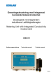
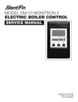
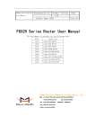
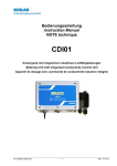
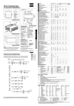
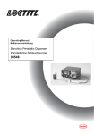
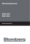
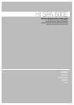
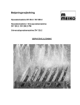
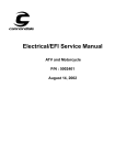
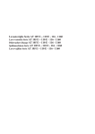
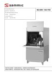
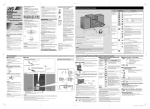
Error messages and troubleshooting
Service Manual
Mike 2
MIKE 2 Modular control system
1. Simplified construction of the GK machine
Rinse aid
container
Klarspüler
Behälter
Rinse aid
dosing
pump (KP)
Klarspüldosierpumpe
(KP)
Detergent
container
Reiniger
Behälter
Detergent
dosing
pump (RP)
ReinigerDosierpumpe
(RP)
door closed
Tür (S1)
zu (S1)
Boiler
Boiler
NiveauLevel
Schalter
switch
(S2)
(S2)
Fresh water
Frischwassersupply pipe
zuleitung
Rinse
"Nachspülung"
Niv.3
Füllventil
Filling
(Y1)
valve
(Y1)
Freier
Air gap
Auslauf
(FA)
(FA)
Boiler
Boiler
Temp.
temperature
sensor
sensor
(BT)
(BT)
BoilerBoiler
Heizung
heater
(BH)
(BH)
DruckBooster pump
steigerungs(DSP)
pumpe
(DSP)
Niveau2
Level
recordingerfassung
3 thresh-hold
1
Tank
values
3 Schwellwerte:
Level 3: critical
Niv.3: level
Kritisches
Niveau
Level
2: operating
Niv.2:
Betriebsservice
niveau
Niv.1: level
Heizung
im W asser
Level 1: heater
in the water
TankTank
Tank
Tank
Heizung
Temp.
heater temperature
(TH) sensor
sensor
(TH)
(TT)
(TT)
SASm (soft
SASm
start system,
mechanical)
LaugenDrain
pump
(LP)
pumpe
(LP)
W aschwash
pumpe
pump
(WP)
(W P)
AbwasserWaste water system
system
Update: 2007-01-13
-1-
-2-
t= 0,06* (P104*P320*P204)/ P321
Rinse aid dosing time in seconds:
Program time/program
cycle
Laufzeit/Program
m zyklus
W aschzeit
Wash(Mindestzeit)
time (minimum)
(Spülprogr.-Param
. SP2) SP2)
(Wash program parameter
Wash
W aschen
t= 0,06* (P105*P320*P204)/ P322
Detergent
Reinigerdosing
time
dosierzeit
Soft start
Sanftanlaufsequence
Sequenz
SASm
Add detergent
Reiniger
zudosieren
Detergent dosing time in seconds:
Program
Program
mstart
Start
VorspülPre-wash
timezeit
(P203)
(P203)
VorPrewash
spülen
Pumpingpzeit
out
Abpum
timevor
before
draining
Abtropfen
(P324)
(P324)
Abpumpen
Pump out
Boiler OK
Boiler
ok ??
time
full??
voll
Eventuell
Start
regeneration if
Regenerierung
needed
starten
Rinse aid
Klarspülerdosing
dosierzeit
Program
Program
mend
Ende
Rinse time
Nachspülzeit
(P204)
(P204)
Rinse
Nachspülen
S2 = 0 ?
Rinse aid
dosage
Klarspüler
dos.
(Überfüllen P305; Tem p. siehe SP1)
- Extension of wash time P 331
- Maximum filling time at initial filling of boiler P308
- Maximum filling time of boiler P309
- Water pressure monitoring P319
- Minimum boiler temperature increase P310
- Minimum tank temperature increase P314
- Maximum number of boiler fillings until level 1 is reached
(filling/heating) P315
- Maximum number of rinse cycles P316
- Maximum time to drop below safety level (level 3) P317
- Maximum pumping out time P318
- Monitoring of boiler level switch S2 1 ->0 P332
- Monitoring of tank level limit P339
unterschritten
to below
level 1
bis Niv.1
Pump out
Abpum
pen
Monitoring
Draining
time
Abtropfzeit
(P325)
(P325)
Drain
Abtropfen
Boiler,Füllen/Heizen
filling/heating
Boiler
(Over full. Temperature, see SP1)
Service Manual
Error messages and troubleshooting
Mike 2
2. Program sequence - GK machine
Service Manual
Error messages and troubleshooting
Mike 2
3. MIKE 2 Electronic controls
3.1 Using the keyboard for programming
Increase value/
move forward
Function field
Decrease value/
move backwards
Accept /
modify
Exit
Value field
Access codes for various user-levels have been defined. Once the complete code has been entered,
the code entered is compared with the internal code table. Depending on the code entered, the
corresponding user level will be accessed. Two access codes are available for each user level; the
first is for restricted access, i.e. no modification of parameters is possible (viewing mode), and the
second gives access to the entire range of functions (viewing and modification).
For control programming, the power supply must be available but the machine must be completely
switched off (no LED must be illuminated).
3.2 Code-input:
View service data:
Modify service data:
View configuration data:
Modify configuration data:
View dosing technology:
Modify dosing technology:
CODE 10000
CODE 10001
CODE 20000
CODE 20022
CODE 40000
CODE 40044
Code entry
To get into the code entry mode, you should keep the key “0” pressed (for around 3 seconds) until
you see
on the display unit.
By pressing the key “0” once again you can leave the programming area at any time.
The digit to be modified will flash.
Press the “I” key to increase the value/code indicated on the display unit, or press the “III” key to
decrease it, or press the “accept” key to save it. The next value will then flash and will be the only one
visible.
-3-
Service Manual
Error messages and troubleshooting
Mike 2
If your entry is incorrect you will exit the code entry procedure and the information code 122 will be
displayed.
If you enter all the digits correctly you will arrive at the chosen level of either service, configuration or
machine data.
3.3 Tree diagram
Service level
All users
Washing
Code-entry
Service level
1-1 Parameter P101 ... P120
1-2 Rinse aid inlet ventilation
1-3 Detergent inlet ventilation
1-4 Start regeneration
1-5 Resetting the partial desalination display
Configuration level
2-1 Parameter P201 ... P240
2-2 View inputs
2-3 View/control outputs
Machine data level
3-1 Parameter P301 ... P350
3-2 Wash programs 1 ... 50
Dosing technology level
4-1 Parameter for dosing the rinsing agent and detergent
or
or
-4-
Service Manual
Error messages and troubleshooting
Mike 2
3.4 Service level
The list of service parameters can be found on this level (parameter numbers 1xx). Here you can view
these or modify them, or you can also call up the ventilation of the rinse and wash hoses.
On the service level, you will first see the display below
This corresponds to viewing / modifying parameters.
This corresponds to rinse aid inlet ventilation.
This corresponds to detergent inlet ventilation.
Press the “I” key to move forwards, press the “III” key to move backwards, or press the key “accept” to
make a selection. You are now at the current level.
You can leave this level by pressing the “0” key.
View/modify parameters
Confirm
the indication by pressing the "accept" key.
The first parameter will now be displayed with a value.
Press the “I” key to go forwards and the “III” key to go backwards, until the parameter you require is
displayed.
Press the “accept” key to confirm the parameter modification. The value will flash. Use the “I” key to
increase the value, or the “III” key to decrease the value, and the “accept” key to save.
You can leave this level by pressing the “0” key.
-5-
Service Manual
Error messages and troubleshooting
Mike 2
Ventilating the rinse aid inlet
Confirm by pressing the “accept” key.
The dosage pump will now be activated and the remaining running time will be indicated.
By pressing the “0” key, you can leave this level. The ventilation will be interrupted.
Ventilating the detergent inlet
Confirm by pressing the “accept” key.
The dosage pump will now be activated and the remaining running time will be indicated.
You can leave this level by pressing the “0” key. The ventilation will be turned off.
Should the ventilation process be insufficient, repeat the process.
3.5 Configuration level
You can find the list of configuration parameters on this level (parameter numbers 2xx). Here you can
view these and modify them. You can also call up the status of the inputs and outputs, or set the
outputs for testing.
On the service level, you will first see the display below:
This corresponds to the viewing/modifying parameters.
This corresponds to viewing the status of inputs.
-6-
Service Manual
Error messages and troubleshooting
Mike 2
This corresponds to viewing and setting the status of outputs.
Press the “I” key to move forwards or the “III” key to move backwards or the “accept” key to make a
selection. You are now at the current level.
Press the “0” key to leave this level.
Viewing / modifying parameters: ( depending on the code entered))
Confirm
this display by pressing the “accept” key.
The first parameter will now be displayed with a value.
Press the “I” key to move forwards or press the “III” key to move backwards, until the parameter you
require is displayed.
Confirm the parameter to be modified by pressing the “accept” key. The value will flash. Press the “I”
key to increase the value, the “III” key to decrease the value, and the “accept” to save the value.
You can leave this level by pressing the “0” key.
Viewing input status
Confirm this display
by pressing the “accept” key.
The first input will now be displayed, with the status
.
Press the “I” key to move forwards and the “III” key to move backwards, until you reach the input you
require.
Display: input set
-7-
Service Manual
Error messages and troubleshooting
Mike 2
Display: input not set
By pressing the “0” key, you can leave this level.
Assignment details for the inputs are given on the assignment list for each machine.
Viewing / modifying output status (according to code entered)
Confirm
this display by pressing the “accept” key.
Viewing:
The first output will now be shown, with status
.
Press the “I” key to move forwards or press the “III” key to move backwards, until the output you
require is displayed.
Modifying:
Press the “accept” key to confirm the modification of the output, the value will flash. Press the “I” key
to modify the value and press the “accept” key to save it.
The output is now set.
You can leave this level by pressing the “0” key.
Viewing / modifying dosing technology level
By entering code 40000 (read only) or 40044 (read / enter), the user can access the new 4th
parameter level summarizing all the dosing technology parameters:
104, P105, P218, P219, P224, P225, P321, P322, P326, P327.
-8-
Service Manual
Error messages and troubleshooting
Mike 2
Assignment details for the outputs are given on the assignment list for each machine.
Assignment list
View inputs / control outputs (example FV 40.2)
Indication
Left
Input / output / other
Conditions
BMK
Plug
XA6
Right
In
1
0/1
Door closed
none
S1
In
2
0/1
Boiler level
none
S2
In
3
0/1
Leak water switch floor
none
S3
In
4
0/1
not occupied
none
In
5
0/1
Initial position wash arm
none
In
6
0/1
not occupied
none
In
7
0/1
not occupied
none
In
8
0/1
not occupied
none
In
9
0/1
Rinse aid empty
none
In
10
0/1
Detergent empty
none
In
11
0/1
Leak water switch dosing unit
none
In
12
0/1
not occupied
none
In
13
0/1
Threshold tank level 1
none
In
14
0/1
Threshold tank level 2
none
In
15
0/1
Threshold tank level 3
none
In
16
0/1
Tank level 4 (option)
none
In
17 0 .. 255
Without function
none
In
18 0 .. 255
Without function
none
In
19
xxx
Boiler temperature in °C or °F
none
In
20
xxx
Tank temperature in °C or °F
none
In
21
xxx
Tank level (unit 1 mm)
none
XA10
In
22 0 .. 255
Option: analog conductance
none
XA5
S5
XA4
XA5
Ou
1
0/1
Wash pump
No leak water
M1
Ou
2
0/1
Booster pump
No leak water
M2
Ou
3
0/1
Wash water pump
No leak water
M5
Ou
4
0/1
Rinse aid - dosage pump
No leak water
M3
Ou
5
0/1
Detergent - dosage pump
No leak water
M4
Ou
6
0/1
Operation indicator
No leak water
-9-
XA1
XA2
Service Manual
Error messages and troubleshooting
Mike 2
Indication
Left
Input / output / other
Conditions
BMK
Plug
XA3
Right
Ou
7
0/1
Filling valve
No leak water
Y1
Ou
8
0/1
SASm soft starter system
No leak water
Y2
Ou
9
0/1
Boiler heating
No leak water
K1
Ou 10
0/1
Tank heating
No leak water, no boiler
heating active
K2
Ou 11
0/1
Without function
none
Ou 12
0/1
Without function
none
Leak water switch condition:
Leak water switch must not have operated.
Heating condition:
Tank / boiler heating are inter-locked (boiler priority)
Tank heating only occurs when boiler heating deactivated.
Parameter list
Par. Configuration
No. options
Use as
Value range
Unit
Factory
setting
Remarks
101
Wash program
key 1
Parameter
1 .. 50
-
1
Assign wash program number
to key 1; assignment
adjustable
102
Wash program
key 2
Parameter
1 .. 50
-
3
Assign wash program number
to key 2; assignment
adjustable
103
Wash program
key 3
Parameter
1 .. 50
-
4
Assign wash program number
to key 3; assignment
adjustable
104
Rinse aid dosage
Parameter
0,10 .. 1,00
ml/litre
water
0.2
Value can be read from the
rinse aid container label
(dependant on water quality)
105
Detergent dosage
Parameter
0,1...20,0
ml/litre
water
2.0
Value can be read from the
detergent container label
(dependant on the hardness
of the water)
106
Hardness degree
Parameter
0 .. 50
°dH
0
Depending on the booster
pump running time and the
hardness of the water (table),
regeneration will be started.
(Number of wash cycles until
regeneration becomes
necessary again)
107
Switch beep on /
off
Parameter
0/1
-
1
Switch acoustic ready
message on / off by beep
108
Modus
“Clear” display
Parameter
0/1
-
“Clear” display
0: via INFO 420
1: display of special
characters
109
Partial / full
desalination
Parameter
0,1,2
-
Partial / full desalination
available?
- 10 -
Service Manual
Error messages and troubleshooting
Mike 2
Par. Configuration
No. options
Use as
Value range
Unit
Factory
setting
available?
Remarks
0: no
1: Partial desalination (TE)
2: full desalination (VE)
110
Hardness litres
per cartridge type
Parameter
0 .. 250
1000 L
111
Total running time
display
Display
5 digits
hrs.
112
Total number of
wash cycles
Display
5 digits
-
Wash cycles / loads,
query only
113
Total number of
wash cycles since
last reset
Display
5 digits
-
Wash cycles / loads,
resetting possible
114
Serial number
Display
8 digits
-
Factory settings can be called
up
115
Condition
Remaining
cartridge capacity
Indication
0 .. 100
%
Only for partial / full
desalination:
TE: indication in %,
VE: 100 = OK;
0 = replace
119
Allow IR
communication
Parameter
0/1
-
1
It is possible to block
communication via IR
interface (0)
120
Load factory
setting service
parameters
Parameter
0/1
-
0
Active only upon power
supply reset ON/OFF.
Important! All changes to
service parameters will be
reversed. Power supply reset
must be carried out within 5
minutes, otherwise factory
settings will not be loaded.
Without power supply reset,
the information 123 will be
displayed.
201
Machine model
Parameter
1 ... 4
-
2
1: FV40.2
2: FV130.2 / FV250.2
3: DV80.2
4: DV120.2 / DV125.2
Important! Only assignment
list and machine sequences
are changed - no parameters
changed.
202
Tank target
temperature
Parameter
10 ... 80
(50 .. 176)
°C/°F
60
Standard for all the wash
programs on one appliance!
Output dependent on
definition
203
Initial rinse time
Parameter
0 ... 8
s.
0
See initial rinse process step
204
Final rinse time
Parameter
4 ... 30
s.
7
Duration of booster pump
activation (running time
- 11 -
When the cartridge’s capacity
is reached (hardness
litres/degree of hardness),
“Replace Cartridge” will be
displayed (INFO 725) (only in
the case of TE)
Running time, query only
Service Manual
Error messages and troubleshooting
Mike 2
Par. Configuration
No. options
Use as
Value range
Unit
Factory
setting
Remarks
limited by P306!!)
205
Operating status
display
Parameter
0 ... 8
-
1
Definition of the information
which is to be switched via the
potential-free contact (see
KD), e.g.:
0 – no information
1 – F/H, ready for washing/
washing or pumping out
2 – F/H, washing or ready for
washing
3 – F/H (Filling/Heating)
4 – Ready for washing
5 – Washing
6 – Pumping out
7 – Error
8 – Not status machine OFF
and Draining
9 – Reserve
10 - Not status Machine OFF
206
Boiler
temperature
display
Display
variant
0/1
-
1
Temperature output definition
0 - nothing
1 - actual value when
filling/ heating, ready for
washing, washing
207
Tank temperature
display
Display
variant
0/1
-
1
Temperature output definition
0 - nothing
1 - actual value when
filling/ heating, ready for
washing, washing
208
Allow emergency
programs
Parameter
0/1
-
0
Release emergency programs
in event of heater failures
209
Release target
value
of increased
boiler
temperature
Parameter
0/1
-
0
Shorten the time until boiler
heating starts by temporarily
increasing the target value
210
Temperature
display in °
Fahrenheit ?
Parameter
0/1
-
0
Standard (0) : °C
Option (1) : °F
Conversion : F = 9/5 * C + 32
or C = 5/9 * (F –32)
211
Fine adjustment
Rinse time
0,0..0,9
Sek.
0,0..0,9
Figures after the decimal point
in P204
212
Leakage dosing
unit
Parameter
0/1
-
1
Activate monitoring
213
Leakage floor pan
Parameter
0/1
-
1
Activate monitoring
214
Automatic hood
opening available
0/1
-
-
0 - off
1 – function activated
215
Wash pressure
reduction
via valve
0/1
-
0
After the end of the SASm
sequence the wash pressure
should be continuously
reduced during the washing
Parameter
Parameter
Parameter
- 12 -
Service Manual
Error messages and troubleshooting
Mike 2
Par. Configuration
No. options
Use as
Value range
Unit
Factory
setting
Remarks
process (-> valve)
216
Tank heating &
washing
simultaneously
Parameter
0/1
-
1
In case of a higher wash
performance
217
Both heaters
simultaneously ?
Parameter
0/1
-
0
Allow heating of boiler and
tank simultaneously?
-> may be necessary to check
power supply
218
Shortage of rinse
aid
Parameter
0/1
219
Shortage of
detergent
Parameter
0/1
223
Optimized boiler
filling time
Parameter
0/1
-
0
Start boiler filling while rinsing
is still active
224
Rinse aid pump
(KP) activation
mode
Parameter
0 .. 4
-
1
Definition activation of KP:
0 – KP = 0; do not activate;
1 – KP; activate according to
calculated running time
2 – KP = booster pump;
activated as booster pump;
3 – KP = wash pump;
activate as wash pump
4 = free
225
Detergent pump
(RP)
activation mode
Parameter
0 .. 4
-
1
Definition activation of KP:
0 – RP = 0; do not activate;
1 – RP; activate according to
calculated running time
2 –RP = booster pump;
activated as booster pump;
3 – RP = wash pump;
activate as wash pump
4 – Option – detergent pump
using negative pressure
dosing.
226
Hood start
available?
Parameter
0/1
-
0
Allow hood start
228
Water softening
available?
Parameter
0/1
-
0
Water softening ?
230
Input/output PCB
model with code 1
Parameter
0 .. 3
-
1
Determination of extended I/O
configuration
0 : not available
231
Input/output PCB
model with code 2
Parameter
0 .. 3
-
0
Determination of extended I/O
configuration
0 : not available
236
Input/output PCB
model with code 7
Parameter
0 .. 3
-
0
Determination of extended I/O
configuration
0 : not available
240
Load factory
settings for
configuration data
Parameter
0/1
-
0
Only effective upon power
supply reset ON/OFF.
Important !
All service parameter
- 13 -
0
Monitoring
Display
0
Monitoring
Display
Service Manual
Error messages and troubleshooting
Mike 2
Par. Configuration
No. options
Use as
Value range
Unit
Factory
setting
Remarks
changes are reset. Power
supply reset must be done
within 5 minutes otherwise the
factory settings will not be
loaded. If power supply not
reset, 123 will be displayed.
For parameters 1xx and 2xx.
3.6 Machine data level
Par.
No.
Machine constant
For use as
Value
range
Unit
301 Offset boiler temperature
measurement
Adjustment
-5 …+5
K
Allow offset
302 ΔT boiler heater
(switch off early )
Parameter
0 ... 10
K
Post-heating compensation
(temperature increase after boiler
heating switched off)
303 Offset boiler temperature for
the initial filling after switching
on
Parameter
0 ... 30
K
Boiler temperature during the initial
filling equal to tank target value plus
this offset
Parameter
0 … 50
sec.
Activation delay to the heater during
boiler filling/heating
305 Overfill boiler
Parameter
0 ... 10
sec.
Extend the filling of the boiler after
the boiler level signal has been
reached
306 Maximum final rinse time
Parameter
0 ... 30
sec.
Maximum booster pump running
time (rinse)
(limit of P204)
307 Boiler heating hysteresis
Parameter
0 ... 3
K
308 Maximum boiler filling time for
first filling
Fault
Parameter
0 ... 600
sec.
Monitor initial filling of boiler (if the
boiler was completely emptied
before switching on)
309 Maximum boiler filling time
Parameter
0 ... 600
sec.
Monitor boiler filling
(S2 must operate)
310 Boiler temperature increases
when heating is ON
Fault
Parameter
0 … 50
K/
Min.
If boiler heating = ON : check that
the actual value increases. First
check after 4 minutes, then at
intervals of one minute)
311 Offset tank temperature
interrogation
Adjustment
-5 …+5
K
Allow adjustment
304
Delay boiler heating
(during filling start)
Remarks
Use two-position controller
312
ΔT tank heating
(switched off early)
Parameter
0 ... 10
K
Post-heating compensation
(temperature increase after boiler
heating switched off)
313
Tank heating hysteresis
Parameter
0 ... 3
K
Use two-position controller
314
Tank temperature increases
when heating is ON
Fault
monitoring
0,0 … 5,0
K/
min
- 14 -
If boiler heating = ON: check that the
actual value increases. First check
Service Manual
Error messages and troubleshooting
Mike 2
Par.
No.
Machine constant
For use as
Value
range
Unit
Remarks
after 5 minutes, then at intervals of 1
minute)
315
Maximum filling cycles
Fault
monitoring
1 ... 50
-
Alternative for maximum tank filling
time. Only on filling/heating
316
Maximum number of final rinse
cycles (for final rinse)
Fault
monitoring
0 ... 10
-
X cycles up to occurrence of fault
(level 2 reached)
317
Maximum time to drop below
tank safety level
Fault
monitoring
1 ... 150
sec
If tank level 3 reached:
-> drain pump ON: maximum
permissible time until water drops
below safety level.
318
Maximum time to pump out to
below level 1
Fault
monitoring
1 ... 150
sec
After the draining time the drain
pump is activated until water level is
below level 1.
319
Check water pressure
Fault
monitoring
1 … 25
320
Booster pump output
Parameter
10 .. 200
321
Rinse agent pump output
Parameter
0.1 ...10
l/h
Rinse agent pump. Output
definition.
322
Detergent pump output
Parameter
0.1 ...20
l/h
Detergent pump. Output definition.
323
Detergent output per impulse
Parameter
0,1 ... 10
ml
Necessary for calculating the dosing
of the detergent using the Hall
sensor
324
Drain pump running time
before the end of the wash
time
Parameter
0 ... 20
sec
Drain pump ON with prior
interrogation whether wash time is
extended
325
Draining pause
Parameter
1 ... 20
sec
Delay time between washing and
pumping out.
326
Rinse agent pipe vent time
Parameter
0 ... 255
sec
Activate rinse agent pump
temporarily to remove air from pipe.
327
Detergent pipe vent time
Parameter
0 ... 100
sec
Activate detergent pump temporarily
to remove air from pipe.
328
Delay wash arm movement
Parameter
0 ... 60
sec
Delay time between start of washing
and start of wash arm rotation
329
Extend wash arm movement
by comparison with the wash
pump
Parameter
0 ... 60
sec
The contents of the wash arm should
be removed as much as possible
330
Delay time before program
end
Parameter
0.0 .. 10.0
sec
Delay time between the end of final
rinse and program end
- 15 -
10 sec If boiler level S2 is not reached
within this period, heating must first
be activated with S2 = 1.
l/min
Calculation of fresh water supply for
dosing quantity of detergent and
rinse agent pump.
Service Manual
Error messages and troubleshooting
Mike 2
Par.
No.
Machine constant
331 Monitor wash time extension
For use as
Value
range
Unit
Remarks
Fault
monitoring
0 ... 500
sec
Wash phase is delayed as the boiler
is not ready (level and temperature)
Emergency program but no part is
faulty (e.g. caused by EW)
Maximum time 5 minutes or when
parameter reached
332
Monitoring boiler level switch
Fault
monitoring
1 ... 10
sec
333
Hardness litres of resin
solution
Parameter
1000 ..
5000
-
334
Operating time EW-Y5
Parameter
0 .. 50
sec.
335
Threshold tank level 1
Parameter
1 .. 150
2 mm Tank level 1
336
Threshold tank level 2
Parameter
1 .. 150
2 mm Tank level 2
337
Threshold tank level 3
Parameter
1 .. 150
2 mm Tank level 3
338
Threshold tank level 4
Parameter
1 .. 150
2 mm Tank level 4 (reserve)
339
Tank level maximum value
Fault
1 .. 150
2 mm Limit value monitoring
349
Tank temperature “ready for
operation” tolerance
Parameter
0 .. 10
K
Tolerance for reaching of “ready for
operation” status prematurely
(If the tank temperature is under the
target temperature and within this
tolerance range and if tank level 2
has already been reached when
starting filling/heating, there will be
an immediate change to “ready for
operation” status)
350
Load factory settings for
machine data?
Parameter
0/1
-
Possible to load factory settings.
Power OFF/ON necessary.
For parameters 1xx, 2xx, 3xx
352 Delay time to start automatic
hood opening
Parameter
0, 1 … 5
sec.
Delay time
0,1 ... 5
Sek.
sec.
Time up to the evaluation of Imax
hood drive, ERR 309
355
Fade-out time for the motor
current, hood drive
Parameter
- 16 -
1-> 0 change at S2 must be
recognised within this time if booster
pump =1
Hardness litres of resin solution
(see regeneration)
Running time EW-Y5 at initial and
second filling of boiler after
regeneration
Service Manual
Error messages and troubleshooting
Mike 2
3.7 Wash program structure
Sequ
ence
no.
Designation
Parameter
1.
TARGET VALUE
Boiler temperature
2.
TARGET VALUE
Wash time
3.
TARGET VALUE
Wash pressure reduction
Value range
Unit
Necessary
memory
Observation
10 .. 92
°C
1 byte
Exception : First machine filling - see
parameter machine data (offset) and
parameter configuration data (target value
tank temperature)
10 ... 1200
sec.
2 bytes
Actual wash time;
phase between pre-rinse and draining
0 ... 3
-
1 byte
If P215 = 1:
Carry out pressure reduction via valve Y3
DV120.2:
0: Ou11 = 0; Ou12 = 0;
1: Ou11 = 1; Ou12 = 0;
2: Ou11 = 0; Ou12 = 1;
3: Ou11 = 1; Ou12 = 1
3.8 Error messages, information
Group
ERR. INFO
No. No. Description
0
Possible cause
System
001
Plug-in EEPROM - fault
EEPROM not available / incorrectly
plugged in / defective
Empty or incorrect EEPROM
Replace EEPROM with correct
parameter set
Plugs to the CPU painted over
002
Internal EEPROM
EEPROM defective, change I/O PCB
003
System error software (operating state)
Software / EMC problem
Short-circuit (moisture) on the sensor
touch panel connection
005
RAM test input/output, internal message
Change input/output PCB
006
ROM test input/output, internal message
Change input/output PCB
007
PROG test input/output, internal message Change input/output PCB
009
Undefined wash program
Outside range of values (1 .. 50)
010
Undefined temperature (wash program)
Incorrect wash program
011
Undefined wash time (wash program)
Set standard wash program
012
Machine model not defined
Incorrect value in parameter P201
013
Boiler heating target value too high at
filling time
Sum of parameters P202 + P303
above maximum value
Reduce P202
- 17 -
Service Manual
Error messages and troubleshooting
Mike 2
Group
ERR. INFO
No. No. Description
Possible cause
014
Boiler heating wash target value too high
Set wash parameter 1 again
Incorrect data transmitted from the PC
Excessive variation in temperature of
feed water.
Check temperature of feed water
Eprom Version 3.0 or 3.0A
015
Tank heating target value too high
Incorrect data transmitted from the PC
Set P202 again
1
General
111
Floor pan leakage
S3, P213
Leak inside the machine
Pump sump / motor / etc.
Defective leak water switch
Repair fault, remove water
112
Dosing unit leakage
Input 11, P212
Dosage pump leak
Hose defective / kinked
Defective dosage pump
Defective measurement electrodes
113
Connection error conductance
conductance 3
Defective interpretation
conductance input 3
Defective cable
Defective I/O PCB
114
Connection error conductance
conductance 4
Defective interpretation conductance
input 4 with galvanic separation
Defective cable
Defective I/O PCB
115
Connection error conductance
conductance 4
Defective interpretation conductance
input 4 without galvanic separation
Defective cable
Defective I/O PCB
116
Connection error analog conductance
Defective interpretation conductance
input 4 analog conductance (option)
Defective cable
Defective I/O PCB
120 Emergency program error reaction active Err 202,205,210,211,302,304,310,311
Limited washing possible
No boiler / tank heating
No fresh water supply
Check system
121 Door not closed
Check connection S1
Switch lever not fixed
Change micro-switch
Check micro-switch adjustment
Replacing a defective I/O circuit board
122 Incorrect password entered
No password / no authorization
Enter code again
- 18 -
Service Manual
Error messages and troubleshooting
Mike 2
Group
ERR. INFO
No. No. Description
Possible cause
123 Factory set parameters activated
P120, P240
To re-set back to factory settings and
parameters, switch power supply
ON/OFF within 5 minutes. After this
parameters will be rejected and factory
parameters will be restored.
Info 123 will disappear.
124 Emergency strategy EEPROM problems
active
Emergency EEPROM program
No EEPROM / empty EEPROM
Incorrect data in plug-in EEPROM
Plug in a new EEPROM with correct
set of parameters.
125 EEPROM is not complete (3 wash
programs)
EEPROM was empty!
128 LowBat (hardware option)
129 Error real-time clock (hardware option)
2
Boiler
201
Level not reached at the correct time
during initial filling
S2
Fresh water supply inadequate (water
faucet closed)
Aquastop hose kinked
Inlet strainer soiled
Aquastop defective
Boiler switch defective
202
Level not reached at correct time during
filling)
S2
Fresh water supply inadequate (water
faucet closed)
Aquastop hose kinked
Inlet strainer soiled
Aquastop defective
Boiler switch defective
203
No change detected by the level switch
when draining
S2
Booster pump defective
Booster pump plug connector loose
Start capacitor defective
Plug connector loose
Boiler level switch defective
No boost pump signal to – from I/O
PCB
No “boiler full” signal from I/O PCB
Check booster pump / S2 with manual
control
- 19 -
Service Manual
Error messages and troubleshooting
Mike 2
Group
ERR. INFO
No. No. Description
Possible cause
204
After rinse time ends, still no change
detected by level switch
205
Temperature increase (Boiler) not reached Boiler heating defective / heating
element thermal fuse
Temperature sensor defective,
incorrect installation position
Boiler contactor defective, circuit
breaker activated
No signal from input/output PCB.
If an energy optimizing device is fitted,
check if it is connected or switched on.
206
Increase in wash time
Boiler not ready for rinsing at right time
(Boiler level / boiler temperature)
Boiler heating defective / heating
element Thermal fuse
Temperature sensor defective
Boiler contactor defective, circuit
breaker activated
No signal from input/output PCB
Eprom Version 3.0 or 3.0A
210
Temperature sensor (Boiler) short circuit
Check sensor cable (plug contacts)
Replace sensor
Attach sensor correctly
211
Temperature sensor (Boiler) interruption
Check sensor cable (plug contacts)
Replace sensor
Attach sensor correctly
212
Actual boiler temperature too high (safety) > 95 °C ?
Contactor contacts sticking
Incorrect sensor / defective sensor
Check probe / lead (contact plug Mike
II XA5)
3
P204, S2
Booster pump defective
Booster pump plug connector loose
Start capacitor defective
Plug connector loose
Boiler level switch defective
No boost pump signal to – from I/O
PCB
No “boiler full” signal from I/O PCB
Check booster pump / S2 with manual
control
Tank
301
When filling tank, level 1 not reached
(number of cycles exceeded)
Tank level evaluation defective
- 20 -
Booster pump output too low
Rinse jets soiled
Air trap soiled
Booster pump rotor defective
Condensate in level pipe
Hose kinked / loose / not watertight
Service Manual
Error messages and troubleshooting
Mike 2
Group
ERR. INFO
No. No. Description
Possible cause
302
Tank draining: level does not fall below
level 1 (pumping out)
Wash water pump output too low
Wash water pump soiled / defective
Outlet hose kinked / blocked
Rotor loose
Wash water pump plug connector
loose
Start capacitor defective
Tank level analysis disrupted
Aquastop not closing completely
No signal from input/output PCB
303
Level does not fall under level 3 after a
period (drain pump ON)
Wash water pump output too low
Wash water pump soiled / defective
Outlet hose kinked / blocked
Rotor loose
Wash water pump plug connector
loose
Start capacitor defective
Tank level analysis disrupted
Aquastop not closing completely
No signal from input/output PCB
304
Temperature increase (Tank) not reached Tank heating defective / thermal fuse
Heating element
Temperature sensor defective,
installed in incorrect position
Tank contactor defective, installed in
incorrect position, circuit breaker
activated.
If an energy optimizing device is fitted,
check if it is connected or switched on.
305
Boiler content is insufficient for rinsing
(level 2 not reached)
Level switch defective
Plug connector loose
Filter covering sieve soiled
Filter soiled
Ventilation valve soiled or defective
Booster pump output too low
Rinse jets soiled
Air trap soiled
Booster pump rotor defective
Condensate in level pipe
Hose kinked / loose / not watertight
306
Maximum level exceeded, tank level
evaluation disrupted
Ventilation valve soiled
Check tank level
Air trap level sensor / check hose
307
Tank level sensor defective (short circuit) Connection plug loose
Sensor defective
Replace input/output PCB
Output voltage < = 0.4 volt
308
Error, hood drive
Motor defective. Limit switch wrongly
set.
309
Error in hood drive. Maximum current
exceeded. Cmax.
Hood jammed, spindle jammed,
motor jammed
- 21 -
Service Manual
Error messages and troubleshooting
Mike 2
Group
ERR. INFO
No. No. Description
Possible cause
310
Temperature sensor (Tank) short circuit
Check sensor cable (plug contacts)
Replace sensor
Attach sensor correctly
311
Temperature sensor (Tank) interruption
Check sensor cable (plug contacts)
Replace sensor
Attach sensor correctly
312
Actual tank temperature too high (security) > 85 °C ?
Contacts of contactor sticking
Incorrect sensor / defective sensor
Check probe / lead (contact plug Mike
II XA5)
4
320 Initial position (of rotating system) not
detected
P221, P222, E5
Switch lever loose
Initial position contactor does not turn
Start capacitator defective
Check micro-switch adjustment
Plug connector loose
Motor for rotating system defective
321 Still at initial position (rotating system)
(Wash arm motor is running)
No signal change
P221, P222, E5
Continuous signal from micro-switch
(short circuit on cable)
See also 320
322 Level 1 not achieved after draining time
Screen blocked
Container filled with water
Foam generation
323 Hood drive active
Possible for hood drive to be active
also when switched off.
324 Hood opening after blockage
Basket under self-closing hood.
Front parts under self-closing hood.
Info remains until next time button
pressed.
325 Wash water pump activated after safety
level has been reached.
Wash water pump activated after
safety level reached.
Message can remain when machine
OFF.
Rinse agent dosage
401
Evaluation of shortage of rinse agent
defective
(Conductance 1)
420 Shortage of rinse agent reported in the
"ready for washing" state
- 22 -
Conductance input 1 (I/O PCB)
Check plug and I/O PCB
P218
Check container dosing
Service Manual
Error messages and troubleshooting
Mike 2
Group
ERR. INFO
No. No. Description
Possible cause
5
Detergent dosage
501
Connection error conductance 2 (LW2)
(detergent)
LW2 (input/output PCB)
520 Shortage of detergent reported in the
"ready for washing" state
P219
Check container dosing
521 Error in pressure dosing
Container empty, dosing unit blocked,
impulses insufficient when valve
dosing activated.
522 Error in pressure dosing
Impulses available while valve dosing
is not piloted.
Valve is defective
7
Regeneration
701
702
Switch S4
Y1, S4
Stop tap closed Y1 defective, S4
defective
The EW intermediate reservoir does not
empty(S4) (Y1=0; DSP2=1)
DSP2 defective / overheated; the
relevant valves EW-Y2, EW-Y3,
EW-Y4 or EW-Y5 are not open
S4 defective
Check by-pass cable with choke
720 Regeneration is running
721 Regeneration impossible, no salt
S5
Add salt
Check reed switch for salt solution
container
722 Add salt
S5
Add salt
Check reed switch for salt solution
container
725 Replacing the cartridge
Cartridge exhausted. Check P 109
- 23 -
Service Manual
Error messages and troubleshooting
Mike 2
Group
ERR. INFO
No. No. Description
9
Possible cause
CAN communication
901
Error bus node code 1
Communication cable not plugged in /
defective
DIP switch S100 wrongly coded - see
wiring diagram
Short circuit in configuration
e.g. level switch poles incorrect
Check, remove short-circuit / plug
902
Error bus node code 2
see Err 901
903
Error bus node code 3
see Err 901
904
Error bus node code 4
see. Err 901
905
Error bus node code. 5
see. Err 901
906
Error bus node code 6
see Err 901
907
Error bus node code 7
see Err 901
2. Power supply (EW) defective
909
Undefined bus nodes detected
P230-236
incorrect input/output components
910
Undefined input/output model
P230-236=0
911
Input/output model not compatible code 1 P230
code on I/O PCB incorrectly defined
912
Input/output model not compatible code 2 P231
code on I/O PCB incorrectly defined
913
Input/output model not compatible code 3 P232
code on I/O PCB incorrectly defined
914
Input/output model not compatible code 4 P233
code on I/O PCB incorrectly defined
915
Input/output model not compatible code 5 P234
code on I/O PCB incorrectly defined
916
Input/output model not compatible code 6 P235
code on I/O PCB incorrectly defined
917
Input/output model not compatible code 7 P236
code on I/O PCB incorrectly defined
- 24 -