1
[ VII Control ]
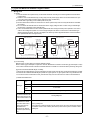
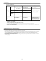
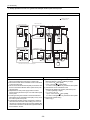
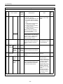
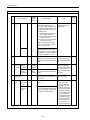
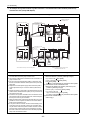
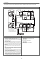
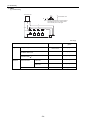
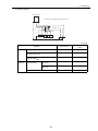
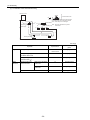
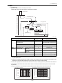
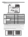
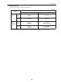
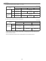
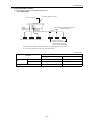
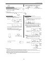
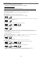
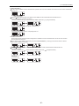
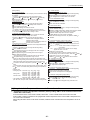
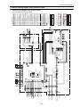
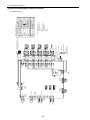
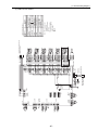
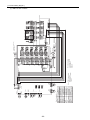
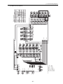
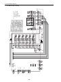
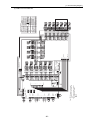
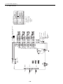
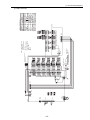
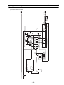
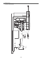
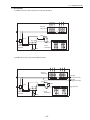
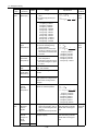
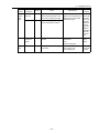
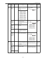
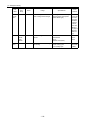
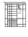
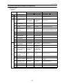
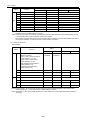
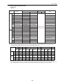
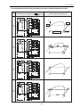
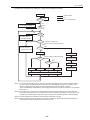
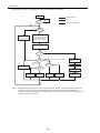
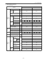
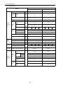
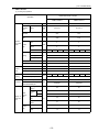
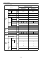
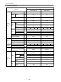
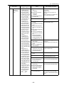
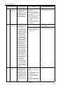
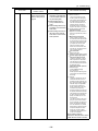
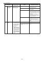
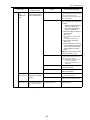
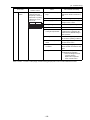
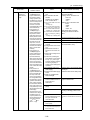
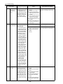
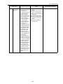
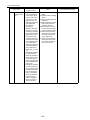
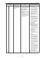
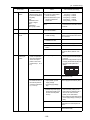
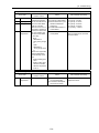
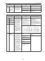
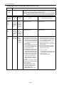
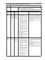
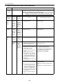
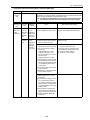
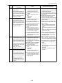
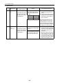
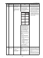
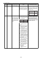
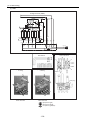
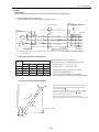
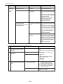
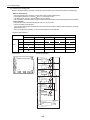
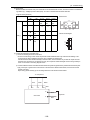
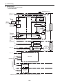
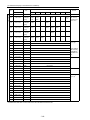
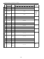
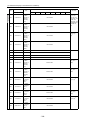
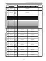
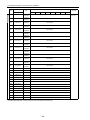
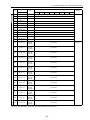
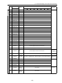
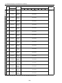
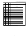
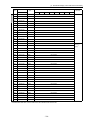
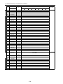
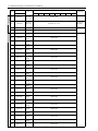
-13- Cooling/heating Circuit Control and General Function of System Equipment <PQRY>
Operation
status
Gas
Two-phase
Liquid
Schematic diagram of refrigerant circuit
High-pressure gas
4-way valve
A
O
Check valve
Selector valve
L
M
Lowpressure
pipe
Heat exchanger
Pressure
Low-pressure two-phase
L
Low-pressure
gas
M
Gas
L
M
Cooling
only
Schematic diagram of refrigerating cycle
Heat exchanger
L
Liquid
A
LEV
L
M
Gas-liquid
separator
High-pressure
liquid
Indoor unit
Highpressure
pipe
Heat source unit
LEV
M
High-pressure
liquid
Enthalpy
(energy)
O
Gas-liquid mixture
BC controller
High-pressure gas
Cooling
N
A
Lowpressure
gas
M
L
Cooling Low-pressure two-phase
N
O
L
M
J G I
L
K H
Cooling
B
N
Cooling
main
L
G
H
Heating
Highpressure
gas
C
M
F
D
Low-pressure gas
E
B
A
N
J
M
High-pressure
liquid
K
L
Lowpressure
two- phase
O
M
High-pressure liquid
O
Heating
only
F
E
High-pressure
two-phase I
A
D C
Highpressure
gas
L
M
L
M
L
M
L
A
M
F
F
High-pressure
liquid
O
Low-pressure gas
Heating
J
A
B
Lowpressure
two- phase
C
D
Heating High-pressure liquid
B
M
C
D
C
D
Heating
B
Heating
main
Cooling
H
K
Highpressure
gas
I
E
G
Low-pressure
gas
B
C
E F
D
F
Lowpressure
two- phase
G
High-pressure
liquid
I
- 139 -
K
J
H
M
A