1
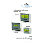
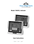
Model 640 Series Indicators
Model 640
User Instructions
ENGLISH
43108-0019 Issue AD
February 2008
2
Model 640 Indicator User Instructions
©Avery Weigh-Tronix LLC, 2006. All rights reserved.
The information contained herein is the property of Avery WeighTronix, Inc and is supplied without liability for errors or omissions.
No part may be reproduced or used except as authorized by
contract or other written permission. The copyright and the
foregoing restriction on reproduction and use extend to all media
in which the information may be embodied.
Avery Weigh-Tronix is a trading name of Weigh-Tronix, Inc
Trademarks and acknowledgements
Avery Weigh-Tronix, Avery Berkel, Dillon, NCI and Salter
Brecknell are registered trademarks in certain jurisdictions.
All third party brands and product names used within this
document are trademarks or registered trademarks of their
respective holders.
IMPORTANT
When programming or configuring the equipment you must ensure
that you comply with all relevant standards and legislation. The
example settings given in this book may not be legal for trade with
the public.
Declarations of compliance
United States
This equipment has been tested and found to comply with the limits for a
Class A digital device, pursuant to Part 15 of the FCC Rules. These limits
are designed to provide reasonable protection against harmful interference
when the equipment is operated in a commercial environment. This
equipment generates, uses, and can radiate radio frequency energy and, if
not installed and used in accordance with the instruction manual, may cause
harmful interference to radio communications. Operation of this equipment
in a residential area is likely to cause harmful interference in which case the
user will be required to correct the interference at his own expense.
Canada
This digital apparatus does not exceed the Class A limits for radio noise
emissions from digital apparatus set out in the Radio Interference
Regulations of the Canadian Department of Communications.
Le présent appareil numérique n’émet pas de bruits radioélectriques
dépassant les limites applicables aux appareils numériques de la Classe A
prescrites dans le Règlement sur le brouillage radioélectrique edicté par le
ministère des Communications du Canada.
European Countries
WARNING
This is a Class A product. In a domestic environment this product may cause
radio interference in which the user may be required to take adequate
measures.
Model 640 Indicator User Instructions
3
CAUTION: DANGER OF EXPLOSION IF BATTERY IS INCORRECTLY
REPLACED. REPLACE ONLY WITH THE SAME OR EQUIVALENT TYPE
RECOMMENDED BY THE MANUFACTURER. DISPOSE OF USED
BATTERIES ACCORDING TO THE MANUFACTURER'S INSTRUCTIONS.
ATTENTION: IL Y A DANGER D'EXPLOSION S'IL Y A REMPLACEMENT
INCORRECT DE LA BATTERIE, REMPLACER UNIQUEMENT AVEC UNE
BATTERIE DU MÊME TYPE OU D'UN TYPE ÉQUIVALENT
RECOMMANDÉ PAR LE CONSTRUCTEUR. METTRE AU REBUT LES
BATTERIES USAGÉES CONFORMÉMENT AUX INSTRUCTIONS DU
FABRICANT.
CAUTION: THE POWER SUPPLY CORD IS USED AS THE MAIN
DISCONNECT DEVICE, ENSURE THAT THE SOCKET-OUTLET IS
LOCATED/INSTALLED NEAR THE EQUIPMENT AND IS EASILY
ACCESSIBLE
ATTENTION: LE CORDON D'ALIMENTATION EST UTILISÉ COMME
INTERRUPTEUR GÉNÉRAL. LA PRISE DE COURANT DOIT ÊTRE
SITUÉE OU INSTALLÉE À PROXIMITÉ DE L'ÉQUIPEMENT ET ÊTRE
FACILE D'ACCÉS".
4
Model 640 Indicator User Instructions
Contents
page
Chapter 1: Introduction .................................................................................................. 7
Front Panel ............................................................................................................... 7
Key Descriptions ................................................................................................ 7
Annunciators ...................................................................................................... 8
Display Messages .................................................................................................... 9
Numeric Entry Procedure ......................................................................................... 9
Getting Started ....................................................................................................... 10
Mounting the Model 640 ......................................................................................... 10
Cable Connections ................................................................................................. 11
Model 640 and 640XL Bottom Panels.............................................................. 11
Model 640M Lower Connector Options............................................................ 12
Connector Pin Descriptions.............................................................................. 13
Chapter 2: User Menu ................................................................................................. 14
Editing The A-LIST ................................................................................................. 15
Accessing the Accumulator Statistics..................................................................... 16
Clearing Accumulators ........................................................................................... 17
Viewing or Changing the Time ............................................................................... 17
Viewing or Changing the Date................................................................................ 18
Entering / Viewing the Audible Keypad Setting ...................................................... 18
Entering / Viewing the Sleep Parameter ................................................................ 19
Setting the Backlight Operation .............................................................................. 19
Entering / Viewing the Language Selection (Not currently functioning).................. 20
Printing a Configuration Report .............................................................................. 20
Chapter 3: Weighing Procedures ................................................................................ 22
Simple Weighing .................................................................................................... 22
Gross/Tare/Net (GTN) Weighing (single tare example) ......................................... 22
Loading or Unloading Consecutive Net Amounts................................................... 23
Loading/Unloading Net Amounts (XM64 Transmitter)............................................ 23
Using Memory Channels to Accumulate ................................................................ 24
Editing Memory Channel List ........................................................................... 24
Accessing Memory Channels........................................................................... 24
Using Memory Channels to Accumulate .......................................................... 24
Clearing the Accumulators ............................................................................... 25
To Clear a Specific Memory Channel............................................................... 25
To Print an Individual Memory Channel ........................................................... 25
To Print All Memory Channels.......................................................................... 26
Manual Hold for Mobile Systems............................................................................ 27
Using Hold Mode for Maintaining Weight Overnight............................................... 27
Animal Weighing Using AUTO-LOC Feature ......................................................... 27
How to Set Up AUTO-LOC............................................................................... 28
Model 640 Indicator Series User Instructions
5
Weighing Individual Animals with Standard Mode AUTO-LOC........................ 29
Weighing Individual Animals with Advanced Mode AUTO-LOC ...................... 30
Printing ................................................................................................................... 31
Chapter 4: Test Menu.................................................................................................. 33
Test Menu Summary.............................................................................................. 33
Access the Test Menu............................................................................................ 34
Test Menu Items .................................................................................................... 34
VOLTS (Input voltage) ..................................................................................... 34
LCD (LCD Display test).................................................................................... 34
KEYPAD (Keypad test) .................................................................................... 35
A/D (View A to D counts) ................................................................................. 35
SERIAL (Testing Serial Ports).......................................................................... 36
INPUT (Testing the Input) ................................................................................ 36
SOFT (Software PN, version and revision) ...................................................... 36
Chapter 5: Remote Displays and XM64 Remote Transmitter ..................................... 38
Remote Displays .................................................................................................... 38
XM64 Wireless Remote Transmitter ...................................................................... 39
Chapter 6: Specifications ............................................................................................ 40
Chapter 7: Appendix: Quick Programming Guide ....................................................... 42
How to Verify the Scale is Weighing Properly ........................................................ 42
To Access the Setup Menu (640)..................................................................... 42
(CONFIG) Finding and Entering a Configuration Code Number...................... 43
Configuration Code Numbers for Common applications:................................. 45
Configuring the Model 640 for Other Brand Weigh Bars and Loadcells .......... 45
Viewing/Entering a Custom Calibration Number.............................................. 46
How to Configure Filtering...................................................................................... 47
Chapter 8: Appendix: Troubleshooting........................................................................ 48
Power ON Problems .............................................................................................. 48
Indicator +/- RANGE Problem ................................................................................ 49
Indicator Over or Under Capacity Problem ............................................................ 49
Inaccurate Weight Readings .................................................................................. 50
Drifting Weight Readings ....................................................................................... 50
Loss of Data: Time & Date or Memory channels .................................................. 50
How to Get Service Repairs................................................................................... 51
6
Model 640 Indicator Series User Instructions
1
Introduction
Included in this manual are the
Model 640, 640XL, 640M
indicators and the RD40XL, RD40,
and RD40RF remote displays.
1.1
This manual covers the information you need to operate your
Avery Weigh-Tronix Model 640 indicator and remote display products.
Major sections of this manual are numbered and headed by a black bar like
Introduction above. Subheadings appear in the left column. Instructions and
text appear on the right side of the page. Occasionally notes, tips, and
special instructions appear in the left column.
Front Panel
The Model 640 indicator face is shown in Figure 1.1.
Figure 1.1 Front panel
Key Descriptions
There are a total of 8 keys. All keys except the ON/OFF will have audible
feedback with low, medium, or high volume settings.
Key names will appear as bold,
upper case words in this manual.
Examples: TARE, G/N, etc.
ON/OFF
Press to turn the unit On/Off
TARE
Press to tare the weight on the scale
ZERO/CLEAR
Press to zero G/N weight. It also is used to clear memory
channels.
G/N
Press to toggle between gross and net weight
Annunciators will appear as italic
words. Examples: G/N, Lb, etc.
Displayed messages will appear as
bold, italic words. Examples:
HELLO, LO-BAT, etc.
Model 640 Indicator Series User Instructions
7
Introduction
Annunciators
8
HOLD/MENU
Press this key to hold a displayed weight. Press again to
release the hold mode. The weight is retained in memory
in case the unit is turned off. When powered up again the
weight reading will still be displayed. This key is also
used to move to the right in the menu structure. Use this
key to also move the numeric entry cursor one space to
the right. This will be explained in the User Menu on
page 14 of this manual.
PRINT/SELECT
Press this key to send data to an attached data collection
device, printer, TDM or computer. This key is also used
to move down in the menu structure.
RM
Press this key to access a memory channel, so the
indicator is ready for accumulations into that channel.
Also, use this key to increment numbers during the
numeric entry procedure.
M+
Press this key to accumulate weights. Also, use this key
to decrement numbers during the numeric entry
procedure.
The Model 640 uses six triangle annunciators for Lb, kg, G/N, Net, Auto and
Motion.
G/N
Indicates the unit is in the gross/net weighing mode.
NET
Indicates the unit is in the net weighing mode.
MOTION
Displayed when there is scale motion. This is based off the
stability window parameters. See the Service Manual.
Lb
Indicates the unit is weighing in pounds.
AUTO
Displayed if the unit is programmed for AUTO-LOC. AUTOLOC is used in animal weighing applications. Reference Animal
Weighing Using AUTO-LOC Feature on page 27.
Kg
Indicates the unit is weighing in kilograms.
Model 640 Indicator Series User Instructions
1.2 Display Messages
1.2
Display Messages
Following are the messages that may appear on the display and what they
mean:
1.3
Message
Meaning
HELLO
Message displayed on power-up sequence for 3 seconds
------
UPPER DASHES, Indicator is in a state of overcapacity, or
analog input is too high.
------
LOWER DASHES, Indicator is in a state of undercapacity,
or analog input is too low.
NO TARE
Displayed when you press the G/N key and there is no tare
weight established.
PRINT
Indicator is transmitting data. Appears after pressing the
print key for a second.
LO-BAT
Alternates on the display between current mode and LOBAT when input voltage is between 9-10 volts.
HOLD
Used when moving a portable system.
L XXXX
XXXX = weigh value Displayed when the indicator is in
AUTO-LOC mode and has locked on a weight.
+RANGE
Displayed when weight input exceeds 8 mV/V.
-RANGE
Displayed when weight input exceeds -8 mV/V.
SHTDWN
Is shown on the display prior to shutting the indicator off
after the sleep timer has expired, or when you press the ON/
OFF key. (10 seconds before sleep timer shutdown the
alarm beeps several times).
CAN’T
Displayed when attempting to access too large of a numeric
entry OR memory channel number greater than 100.
Numeric Entry Procedure
Anytime you need to enter numeric values, use the keys as described below.
The note at left will appear throughout areas of the manual to remind you of
the key presses needed to enter numbers.
EXAMPLE: To enter a number of 5230:
1.
At the data entry screen, press the RM key several times until…
5 is displayed
2.
Press the HOLD/MENU key and…
5_ is displayed
3.
Press the RM key several times until…
52 is displayed.
4.
Repeat process until…
5230 is shown.
Model 640 Indicator Series User Instructions
9
Introduction
1.4
Getting Started
Before using your new Model 640 indicator:
• please verify that everything has been properly connected. Reference
Cable Connections on page 11
• If you are mounting the indicator, see the next section: Mounting the
Model 640.
• check the scale system to ensure proper units are set (lb, kg)
• verify the system is weighing properly. Do this by following these steps:
1.
In the gross weighing mode, zero the indicator by pressing the ZERO/
CLEAR key
2.
Stand on the scale and note the scale reading.
If the weight reading is correct, your system is working properly
and you can continue with operation of the system.
If the weight reading is not correct, read through Appendix: Quick
Programming Guide on page 42. This will tell you how to access
the SETUP menu to change the Configuration Code Number
(CCN). This should get your system up and running properly. If you
have further problems, call your local dealer or Avery WeighTronix.
1.5
Mounting the Model 640
The Model 640 mounts on a quick-detach bracket. Weld or bolt the quickdetach bracket into place, as follows:
1.
•
•
10
Choose a mounting location that is
convenient for operation of the indicator, and
protected from moving parts or from other moving machinery.
2.
Hold the indicator at the proposed mounting location, and verify that
the display is legible and the controls accessible.
3.
Positioning the quick-detach bracket with the wider end at the top,
mark the desired mounting location. If bolting, use the quick-detach
bracket as a template and mark and drill holes.
4.
Weld or bolt the quick-detach bracket at the appropriate location. If
bolting, use double nuts or self-locking nuts to protect both indicator
and machinery.
5.
Insert the indicator bracket into the quick-detach bracket and push it
down into place.
6.
For mobile applications, wrap and twist a strong wire around the
indicator bracket and the quick-detach bracket, through the slotted
hole provided, to stabilize the mounting. See the illustration below.
Model 640 Indicator Series User Instructions
1.6 Cable Connections
1.6
Cable Connections
Below are illustrations to help you make the proper connections to the
different versions of the Model 640.
Model 640 and 640XL
Bottom Panels
Model 640 Indicator Series User Instructions
11
Introduction
Model 640M Lower
Connector Options
640M INDICATOR
Single 5-Pin, w/RS232 & RD40RF
MODEL 640M
Contains FCC ID:
R68WIPORT
FAI
, MN
SA
NOT L AL FOR T
DE
10-17 VDC @ 500mA
S/N: YYMMXXXXX
RS-232
Antenna
2-Pin Power Input
(+12VDC)
5-Pin J-Box
640M INDICATOR
Single 5-Pin, w/RS232 & RD40 or RD40XL
ODEL 640M
FAI
, MN
SA
NOT L AL FOR T
E
7 VDC @ 500mA
S/N: YYMMXXXXX
RD40/XL
2-Pin Power Input
(+12VDC)
RS-232
5-Pin J-Box
640M INDICATOR
AMP 4-Pin, w/RS232 & RD40RF
Contains FCC ID:
R68WIPORT
MODEL 640M
FAI
, MN
SA
NOT L AL FOR T
DE
10-17 VDC @ 500mA
S/N: YYMMXXXXX
RS-232
Antenna
4-Pin AMP J-Box
4-Pin Power Input
(+12 VDC)
640M INDICATOR
AMP 4-Pin, w/RS232 & RD40RF or RD40XL
DEL 640M
FAI
, MN
SA
NOT L AL FOR T
17 VDC @ 500mA
S/N: YYMMXXXXX
RD40/XL
RS-232
4-Pin Power Input
(+12 VDC)
4-Pin AMP J-Box
640M INDICATOR
2 W/B 5-Pin, w/RS232
ODEL 640M
FAIRMONT, MN USA
NOT LEGAL FOR T
E
2-Pin Power Input
(+12VDC)
12
RS-232
17 VDC @ 500mA
S/N: YYMMXXXXX
2 Weigh Bar
(Alley or Chute Weigh)
Model 640 Indicator Series User Instructions
1.6 Cable Connections
Connector Pin
Descriptions
Model 640 Indicator Series User Instructions
13
User Menu
2
User Menu
This section takes you through the User menu. You will use this menu for
many scale functions.
Access this menu from the G/N mode by pressing the HOLD/MENU key for
two beeps. See Figure 2.1.
Figure 2.1 User Menu
14
Model 640 Indicator Series User Instructions
Below is a summary of the items in this menu, followed by a comprehensive
explanation of each item:
2.1
•
A-LIST
Used to edit the memory accumulator descriptions
•
A-STAT
Used to access statistics of the memory accumulator
channels
•
CLR.ACC Use this to clear accumulator channels
•
TIME
Use to set the time
•
DATE
Use to set the date
•
VOLUME Use to set the volume of the audible key buzzer.
•
SLEEP
•
BKLGHT Use to set the backlight brightness.
•
NATION
•
REPORT Use to print out indicator ‘system configuration settings’.
Use to set the amount of inactive time before the indicator
turns itself off.
Use to set the spelling of messages in the following:
English, Spanish, French, German, Dutch and Danish
Editing The A-LIST
If the application requires alphanumeric channel names, go through the
memory channel list, and edit their descriptions accordingly. Example, if you
want to record grain cart loads from five different fields, then create a list of
FIELD1, FIELD2, …FIELD3. Now the custom names of the memory
channels can be used, otherwise all memory channels will be the default
descriptions of MEM.001, MEM.002, etc.
1.
From the G/N mode, press HOLD/MENU for 2 beeps…
A-LIST is shown on the display.
2.
Press the PRINT/SELECT key…
EdiT is displayed
3.
Press PRINT/SELECT again and …
MEM.001 is displayed, or the last memory channel accessed.
If reviewing the memory channel list, to edit, get to displayed
channel by pressing and holding on the HOLD/MENU key, or use
the RM^ key in conjunction with the HOLD/MENU key to go directly
to a memory channel to edit its name.Example: Press RM^ three
times to reach 2, and then press PRINT/SELECT and MEM.002 will
be displayed on the screen.
4.
Model 640 Indicator Series User Instructions
Press G/N three times to return to G/N weighing mode.
15
User Menu
2.2
Accessing the Accumulator Statistics
This section allows you to access the accumulator statistics.
1.
From the G/N mode, press and hold the HOLD/MENU key for two
beeps (2 sec), then release…
A-LIST is displayed.
2.
Press the HOLD/MENU key once…
A-STAT is displayed. This stands for accumulator statistics.
3.
Press the PRINT/SELECT key…
WT.TOT is displayed.
4.
Press the PRINT/SELECT key…
Total weight accumulated in all the accumulators is displayed.
5.
Press the PRINT/SELECT key…
WT.TOT is displayed.
6.
Press the HOLD/MENU key once…
CNT.TOT is displayed.
7.
Press the PRINT/SELECT key…
The total number or count of accumulations performed is shown.
8.
Press the PRINT/SELECT key…
CNT.TOT is displayed.
9.
Press the HOLD/MENU key …
AVG.TOT is displayed.
10. Press the PRINT/SELECT key…
The average weight of all accumulations is displayed.
11. Press the PRINT/SELECT key…
AVG.TOT is displayed.
12. Press the HOLD/MENU key …
PRINT is displayed.
13. Press the PRINT/SELECT key …
The statistics printout is transferred to the TDM or printer device. A
sample is shown below:
04-25-2006
14:20:26
TOTAL WEIGHT: 1938370 lb
AVG. WEIGHT: 44050 lb
TOTAL COUNT: 44
14. Press the G/N key to return to A-STAT. Press G/N key again to return
to G/N weighing mode.
16
Model 640 Indicator Series User Instructions
2.3 Clearing Accumulators
2.3
Clearing Accumulators
This section allows you to clear the accumulators.
1.
From the G/N mode, press and hold the HOLD/MENU key for two
beeps (2 sec), then release…
A-LIST is displayed.
2.
Press the HOLD/MENU key repeatedly until…
CLR.ACC is displayed.
3.
Press the PRINT/SELECT key…
NO is displayed.
4.
Press the HOLD/MENU key…
YES is displayed.
5.
Press the PRINT/SELECT key…
WAIT is displayed while clearing, then MEM.CLR is briefly
displayed, then unit returns to the G/N weighing mode.
2.4
Viewing or Changing the Time
The Model 640 has standard battery backed time and date features. The
time can be configured for 24 hour or 12 hour clock for printouts in the 640
menu, but must always be entered first as 24 hr entry:
1.
From the G/N mode, press and hold the HOLD/MENU key for two
beeps (2 sec), then release…
A-LIST is displayed.
2.
Press the HOLD/MENU key repeatedly until…
TIME is displayed.
3.
Press PRINT/SELECT and …
Current time is shown ticking.
4.
Press PRINT/SELECT to accept displayed time…
TIME is displayed.
OR
To change time, use the numeric entry procedure to enter HHMMSS
and press PRINT/SELECT to accept…
TIME is displayed.
5.
Press the G/N key…
Returns to the G/N mode.
Model 640 Indicator Series User Instructions
17
User Menu
2.5
Viewing or Changing the Date
The indicator has battery backed time and date standard. The date can be
entered as follows:
1.
From the G/N mode, press and hold the HOLD/MENU key for two
beeps (2 sec), then release…
A-LIST is displayed.
2.
Press the HOLD/MENU key repeatedly until…
dATE is shown.
3.
Press the PRINT/SELECT key
MMddYY (lb)
or
ddMMYY(kg) is displayed momentarily, then current date setting is
shown.
4.
Use the numeric entry procedure to enter the date. See note at left.
(lb) enter MMddYY
5.
(kg) enter ddMMYY
Press the PRINT/SELECT key to accept the displayed date…
dATE is shown.
6.
Press the G/N key…
Indicator returns to the G/N mode.
2.6
Entering / Viewing the Audible Keypad Setting
The Model 640 keys have audible feedback that can be configured for off,
low, medium, or high. (Default is high)
1.
From the G/N mode, press and hold the HOLD/MENU key for two
beeps (2 sec), then release…
A-LIST is displayed.
2.
Press the HOLD/MENU key repeatedly until…
VOLUME is displayed
3.
Press the PRINT/SELECT key…
Current setting is shown.
4.
Press HOLD/MENU repeatedly until appropriate setting is shown,
then press PRINT/SELECT…
VOLUME is displayed.
5.
Press the G/N key…
Returns to the G/N weighing mode.
18
Model 640 Indicator Series User Instructions
2.7 Entering / Viewing the Sleep Parameter
2.7
Entering / Viewing the Sleep Parameter
The Model 640 has a sleep mode that can shut the unit off if the following
conditions occur:
•
The indicator doesn’t see any keys being pressed, or
•
The weight hasn’t changed by more than 1% over the number of
minutes that was entered for the sleep setting.
Setting the Sleep setting (DEFAULT = 0, for off)
1.
From the G/N mode, press and hold the HOLD/MENU key for two
beeps (2 sec), then release…
A-LIST is displayed.
2.
Press the HOLD/MENU repeatedly until…
SLEEP is displayed.
3.
Press the PRINT/SELECT key…
Current setting is displayed.
When the unit goes to sleep, the
unit will first activate the audible
alarm, and user has 10 seconds to
press a key to reset the SLEEP
timer. If a key hasn’t been pressed
within these 10 seconds the display
shows SHTDWN, and the unit
shuts off.
4.
Use the numeric entry procedure and enter in the sleep shutoff setting
from 0-99 minutes…
Entered value is displayed.
5.
Press the PRINT/SELECT key…
SLEEP is displayed.
6.
Press the G/N key…
Returns to the G/N mode.
2.8
Setting the Backlight Operation
The Model 640 has a backlight you can configure. Follow these steps to
configure backlight operation.
1.
From the G/N mode, press and hold the HOLD/MENU key for two
beeps (2 sec), then release…
A-LIST is displayed.
2.
Press the HOLD/MENU key repeatedly until….
BKLGHT is displayed.
3.
Press the PRINT/SELECT key…
Current setting is displayed. (ON or OFF)
4.
Press the HOLD/MENU key to toggle between the two settings. Press
PRINT/SELECT when your choice is displayed. If you choose ON…
LEVEL is displayed. Use this to set the illumination level of the
backlight (10% to 100%).
5.
Press the PRINT/SELECT key to access the level…
Current setting is displayed. (100% is default value)
6.
Scroll through the choices by repeatedly pressing the HOLD/MENU
key. Press PRINT/SELECT when your choice is displayed.
LEVEL is displayed.
Model 640 Indicator Series User Instructions
19
User Menu
7.
Press the HOLD/MENU…
TIMER is displayed. Use this to set the amount of time which must
pass with no scale or indicator activity before the unit shuts down
the backlight for power saving.
8.
Press the PRINT/SELECT key to access the timer function…
Current setting is displayed.
9.
Use the numeric entry procedure to enter a choice in seconds (0-99).
Press PRINT/SELECT to accept your choice.
TIMER is displayed.
10. Press G/N key twice…
BKLGHT is displayed.
11. Press the G/N key…
Indicator returns to the G/N mode.
2.9
Entering / Viewing the Language Selection (Not currently functioning)
The Model 640 has a selectable language for the displayed messages and
reports.
1.
From the G/N mode, press and hold the HOLD/MENU key for two
beeps (2 sec), then release…
A-LIST is displayed.
2.
Press the HOLD/MENU key repeatedly until….
NATION is displayed.
3.
Press the PRINT/SELECT key…
Current setting is displayed.
4.
Use the HOLD/MENU keys and scroll to the proper language
selection…
Proper selection is shown.
5.
Press the PRINT/SELECT key to accept displayed choice…
NATION is displayed.
6.
Press the G/N key…
Returns to the G/N mode.
2.10
Printing a Configuration Report
1.
From the G/N mode, press and hold the HOLD/MENU key for two
beeps (2 sec), then release…
A-LIST is displayed.
2.
Press the HOLD/MENU key repeatedly until….
REPORT is displayed.
3.
Press the PRINT/SELECT key…
A configuration report on the current status of your indicator is
output through the RS-232 port to your connected device.
20
Model 640 Indicator Series User Instructions
2.7 Entering / Viewing the Sleep Parameter
4.
Press the G/N key…
Returns to the G/N mode.
A sample report is shown below:
----------------------------System Configuration Settings
04-25-2006
11:29:00
----------------------------PART :
60259-0026
REV
:
X35
User's Menu
----------VOLUME:
SLEEP TIMER :
BKLGHT:
LEVEL :
NATION:
HIGH
OFF
ON
100%
ENGLSH
640 Setup Menu
-------------MODE :
CONFIG:
1.0 mV/V:
O-CAP :
DIV
:
PRINT FORMAT:
CLOCK :
DATE :
AUT.LOC:
640
14330
40000 lb
200000 lb
10 lb
G-T-N w/ Date-Time
24 HR
MM-DD-YY
OFF
AUT.ACC:
OFF
INPUT1:
INPUT2:
UPDATE:
AVERGE:
FILTER:
CONST :
WINDOW:
AZT
:
STABLE:
RS232 :
BAUD :
DATA :
PARITY:
HAND :
LAYOUT:
ENQR :
AUTO :
STD
STD
5 Hz
30
ON
2
0 lb
OFF
1 DIV
Factory Menu
-----------FAC.SPN:
Model 640 Indicator Series User Instructions
9600
8
NONE
NONE
STD
5
OFF
99779
21
Weighing Procedures
3
Weighing Procedures
This section covers the procedures for different weighing processes.
3.1
Simple Weighing
Establishing zero here is the same
as doing the calibration zero.
1.
If unit is in AUTO-LOC mode and L
is displayed, to zero the scale,
press and hold the ZERO/CLEAR
key for two seconds.
2.
Press ON…
Display shows HELLO then the current weight value is displayed.
Press G/N and access gross mode…
Live scale weight is displayed in the G/N weighing mode.
3.
Remove all material from the scale and press ZERO/CLEAR
0 is displayed, and the system is zeroed.
3.2
Gross/Tare/Net (GTN) Weighing (single tare example)
The same zero point established at
this point is the same calibration
zero. If a system is set at 20000 lb,
and a user tares at 18000, then the
system can only allow another
2000 lb before displaying (- - - - - -)
upper dash lines for overcapacity.
If no TARE weight has been
established, pushing G/N key
shows NO TARE.
For GTN weighing (weighing net amounts), follow these steps:
1.
Press ON…
Display shows HELLO then the current weight value is displayed.
2.
Press G/N to access the gross mode…
Live scale weight is displayed in the G/N weighing mode.
3.
Remove all material from the scale and press ZERO/CLEAR
0 is displayed, and the system is zeroed.
4.
Place material to be tared on the scale…
Weight of material is displayed.
5.
Press the TARE key to tare the weight from the display…
0 weight is displayed and the Net annunciator lights to indicate
there is an active tare weight.
6.
Place the material to be weighed on the scale…
Net weight is displayed.
7.
Remove the weighed material from the scale (leaving the tared item).
8.
Repeat steps 6 through 7 for each weighment using the same tare
weight.
9.
To remove the tare weight, press the G/N key to return to gross weigh
mode, then press the ZERO/CLEAR key…
The tare weight is removed and you can repeat this process to
weigh more material with a different tare.
22
Model 640 Indicator Series User Instructions
3.3 Loading or Unloading Consecutive Net Amounts
3.3
Loading or Unloading Consecutive Net Amounts
This procedure allows the user to load/unload a series of net amounts. This
procedure is ideal for TMR mixers, weigh carts, grain carts, etc. for viewing
and recording net amounts of material loaded and unloaded.
1.
In gross mode, press the ZERO/CLEAR key to zero the indicator when
the mixer or scale system is empty.
2.
After initial amount is placed on the scale, press the TARE key…
Weight is tared off and goes into net mode, showing 0 weight.
3.
Load or Unload material as needed…
Shows + when loading and a – value when unloading.
3.4
4.
When the display reaches the proper amount, stop loading or
unloading material.
5.
Repeat steps 2 through 4 until complete.
Loading/Unloading Net Amounts (XM64 Transmitter)
This procedure allows the user to load/unload a series of ingredient/unload
amounts by using the XM64 transmitter/receiver. This procedure implies that
the end user knows the net amounts that must be loaded or unloaded. The
XM64 gives the user the ability to tare or zero each ingredient and view the
net amount as loading or unloading. It also can be used to indicate the G/N
amount between ingredients and can return the indicator to the G/N mode
when done loading by holding down on the XM64 for three or more seconds.
1.
In gross mode, press the ZERO/CLEAR key to zero the indicator when
the mixer or scale system is empty.
2.
After material is placed on the scale, press the XM64 key…
Weight is tared off and goes into net mode, showing 0 weight.
3.
Load or Unload material as needed…
Shows + when loading and a – value when unloading.
4.
When the display reaches the proper amount, stop loading or
unloading material.
5.
Repeat steps 2 through 4 until complete.
You may now view the G/N weight by pressing and holding the XM64 button,
once. Releasing the button if within three seconds unit returns to the net
mode showing zero.
If you are done loading and now want to return to the G/N mode for
unloading, press and hold the XM64 for more than three seconds.
Model 640 Indicator Series User Instructions
23
Weighing Procedures
3.5
Using Memory Channels to Accumulate
The Model 640 has 100 memory channels available for accumulating
weights. This can be helpful in accumulating loads of feed on a mixer, grain
cart or weigh cart yields, or setting up groups of livestock. Each channel will
also have the total number of accumulations obtained, total weight and the
average weight of all weights accumulated, both total and for each individual
channels.
Editing Memory Channel
List
If the application requires alphanumeric channel names, go through the
memory channel list, and edit their descriptions accordingly. Example, if you
want to record grain cart loads from five different fields, then create a list of
FIELD1, FIELD2, …FIELD3. Now the custom names of the memory
channels can be used, otherwise all memory channels will be the default
descriptions of MEM.001, MEM.002, etc.
1.
From the G/N mode, press HOLD/MENU for 2 beeps…
A-LIST is shown on the display.
2.
Press the PRINT/SELECT key…
EdiT is displayed
3.
Press PRINT/SELECT again and …
MEM.001 is displayed.
If reviewing the memory channel list, to edit, get to displayed
channel by pressing and holding on the menu key, or use the RM^
key in conjunction with the HOLD/MENU key to go directly to a
memory channel to edit its name. Example: Press RM^ three times
to reach 2, and then press PRINT/SELECT and MEM.002 will be
displayed on the screen.
Accessing Memory
Channels
4.
Press G/N three times to return to G/N weighing mode.
1.
From the G/N mode, press the RM^ key…
MEM.001 is shown or the last accessed channel.
This will now access the MEM.001 channel. If you want any other
channel either use the HOLD/MENU key to scroll to the proper
channel, or use the RM^ and the HOLD/MENU key to access
directly to channel XX, then press PRINT/SELECT.
2.
Press HOLD/MENU twice , and…
MEM.003 is shown
Using Memory Channels to
Accumulate
3.
Either press the G/N key to return to gross weighing, or wait 3
seconds and it will automatically return to the gross weighing mode.
1.
Press M+ and the following is displayed:
Active memory channel is shown
M+
TOTAL
Actual Accumulated total is shown
2.
24
If accumulated in error, press and hold M+ until the second beep and
the following is displayed…
Model 640 Indicator Series User Instructions
3.5 Using Memory Channels to Accumulate
Active memory channel is shown
DELETE
TOTAL
New Actual Accumulated total is shown
Clearing the Accumulators
1.
From the G/N mode, press and hold on the HOLD/MENU key for two
beeps (2 sec) and release…
A-LIST is shown.
2.
Press HOLD/MENU twice…
CLR.ACC is shown
3.
Press PRINT/SELECT…
NO is displayed.
4.
Press HOLD/MENU…
YES is displayed.
5.
Press PRINT/SELECT…
WAIT is displayed, then MEM.CLR. Once the unit is done clearing
accumulators CLR.ACC is displayed again.
To Clear a Specific Memory
Channel
6.
After the accumulators are cleared press G/N to return to the G/N
weighing mode.
1.
Access the proper memory channel.
2.
From the G/N mode, press and hold ZERO/CLEAR key until the
second beep…
MEM.XXX is displayed then MEM.CLR is displayed. MEM.XXX is
now cleared.
To Print an Individual
Memory Channel
1.
From the G/N mode, press the RM key…
MEM.001 is displayed or the last accessed memory channels.
This will now access the MEM.001 channel. If you want any other
channel either use the HOLD/MENU key to scroll to the proper
channel, or use the RM and the HOLD/MENU key to access
directly to channel XX, then press PRINT/SELECT.
2.
Once the proper channel is displayed, press PRINT/SELECT and the
following report will be printed to the printer or TDM module.
Before printing PR-RM is shown on the display…
Accumulators can go as far as
99,000,000.
3.
Model 640 Indicator Series User Instructions
09-11-2007
11:12:17
CHANNEL:
NAME:
1
MEM.001
ACCUM. WEIGHT:
ACCUM. COUNT:
ACCUM. AVERAGE:
1000000 lb
20
50000 lb
The indicator automatically returns to the gross weighing mode.
25
Weighing Procedures
To Print All Memory
Channels
1.
Press RM^…
Latest memory channel is displayed.
2.
Press PRINT/SELECT for 2 beeps (2 secs)
PR-ALL is momentarily displayed and information is transmited.
3.
The indicator will only print out
memory channels that have
accumulated weight amounts.
Indicator returns to gross weighing mode.
Mem channel printout
04-25-2006
14:17:19
MEM CH
COUNT
AVG WT
TOTAL
FIELD1
FIELD2
CUSTOM
18
14
12
29980 lb
51390 lb
56620 lb
539550 lb
719390 lb
679430 lb
TOTAL
44
44050 lb
1938370 lb
Figure 3.1 Menu
26
Model 640 Indicator Series User Instructions
3.6 Manual Hold for Mobile Systems
3.6
Manual Hold for Mobile Systems
The Model 640 has a manual hold using the HOLD/MENU key to prevent a
zero shift from occurring on any portable scale system (i.e. mixer, weigh cart,
grain cart, etc.). To use the HOLD/MENU key to prevent any small zero
shifts from occurring while moving a system over rough farm terrain, follow
these steps.
When using the hold mode user
must be sure hold mode has been
deactivated when loading or
unloading to the mixer.
1.
In the G/N Mode ,before moving the mixer system press HOLD/
MENU…
HOLD will be displayed.
2.
Now move the system and when reaching the new loading or
unloading point, press either the HOLD/MENU or G/N key…
G/N weight will be displayed.
3.7
Using Hold Mode for Maintaining Weight Overnight
The Model 640 has a HOLD/MENU key to prevent minimal scale weight
shifts due to temperature changes.
1.
In the gross weighing mode, when you are finished with the scale for
the day, but material is left on the scale, press the HOLD/MENU key…
HOLD is displayed.
2.
Turn the system off for the night.
3.
The following day turn the unit on by pressing the ON/OFF key…
HOLD is displayed.
4.
Press G/N key and…
Exact weight from the previous day is displayed.
3.8
Animal Weighing Using AUTO-LOC Feature
The Model 640 has a feature called AUTO-LOC. It is specifically designed
for use in weighing livestock. Once the indicator has determined the animal’s
weight, the indicator display automatically locks on that weight. The weight
reading will not change as long as the animal is on the scale. This makes the
weight easy to record since the numbers are not rapidly changing as the
animal moves on the scale.
AUTO accumulate feature can be
turned on or off to work with AUTOLOC. Refer to Figure 7.3 Table for
5th CCN Digit on page 44 to
choose a 5th digit of the CCN
which will turn on the accumulator.
There are two modes in the Auto–LOC feature:
Standard LOC Mode
In standard mode, an animal’s weight is locked on the display until the
animal leaves the scale.
Advanced LOC Mode
In advanced mode, an animal’s weight is locked on the display until the next
animal comes onto the scale.
Model 640 Indicator Series User Instructions
27
Weighing Procedures
How to Set Up AUTO-LOC
Follow these steps to set up the AUTO-LOC feature:
1.
Access the Setup menu from the G/N mode. Press and hold the
HOLD/MENU key for three beeps (3 seconds), then release…
SET.PAS is displayed.
2.
Use the numeric entry procedure, described at left, to enter the
password 640. Press PRINT/SELECT to accept it…
640 is shown
3.
Press PRINT/SELECT once more…
CONFIG is displayed. Change your current configuration code
number to one that turns AUTO-LOC on. Refer to Figure 7.3 Table
for 5th CCN Digit on page 44. Once you have your five digit
number, enter it as follows:
4.
From CONFIG, press PRINT/SELECT…
Current code number is shown.
If attempting to enter an invalid
number display will show CAN’t
and return to CONFIG.
5.
Use the numeric entry procedure to enter the new number and press
the PRINT/SELECT key when finished.
CONFIG is shown.
6.
Press the HOLD/MENU key several times until…
AUT.LOC appears. The AUTO-LOC menu selection only shows up
when a configuration code number turns on this feature.
This menu item is where you choose standard or advanced LOCK,
minimum weight (MIN.WT), and release tolerance (REL.TOL)
appropriate for the livestock application.
7.
Press the PRINT/SELECT key…
MODE is displayed.
8.
Press the PRINT/SELECT key…
STD.LOC is displayed. This is the standard LOCK. Toggle between
this and the ADV.LOC by pressing the HOLD/MENU key.
9.
When your choice is displayed, press the PRINT/SELECT key…
Your choice is selected and MODE is displayed.
EXAMPLE: If you are weighing
1200 pound cattle, you may set the
minimum weight at 800 pounds
and a release tolerance of 25%.
Anything thing that goes on the
scale that weighs less than 800
pounds (like a person or the
neighborhood dog) will not cause
the weight to lock. When an animal
steps off the scale and the weight
drops by at least 300 pounds (25%
of 1,200 pounds), the system will
reset to lock on the next weight
above 800 pounds.
28
10. Press the HOLD/MENU key…
MIN.WT is displayed. This is where you set the minimum weight
that must be on the scale to activate the AUTO-LOC feature. This
prevents smaller weights from locking on the display. See example
at left.
11. To set the minimum weight, press the PRINT/SELECT key…
Use the numeric entry procedure to enter the minimum weight
value.
12. When the value is entered, press the PRINT/SELECT key to accept it
and…
MIN.WT is displayed.
13. Press the HOLD/MENU key…
Model 640 Indicator Series User Instructions
3.6 Manual Hold for Mobile Systems
REL.TOL is displayed. This is the release tolerance. This iset in
steps 11 and 12 which must be removed from the scale before the
AUTO-LOC resets. See example in the left margin of page 28.
14. Press the PRINT/SELECT key…
Use the numeric entry procedure to enter the release tolerance in
percentage of the minimum weight.
15. When the value is entered, press the PRINT/SELECT key to accept it
and…
Your choice is selected and REL.TOL is displayed.
You can exit the menu and return to normal weighing mode by repeatedly
pressing the G/N key. If, during operation the AUTO-LOC feature seems
very slow, this can be due to excessive weight fluctuations. In this case you
can access the Setup menu and increase the FILTER-CONSTANT
parameter until it works properly. Reference How to Configure Filtering on
page 47 for instructions on adjusting the filtering.
Weighing Individual
Animals with Standard
Mode AUTO-LOC
The following describes how a Model 640 can be used for weighing and
recording an animal’s weight automatically on a single animal livestock scale
with standard mode AUTO-LOC. Unit must be setup for AUTO-LOC and set
for standard (STD.LOC) mode.
1.
Turn indicator on, press the G/N key to access the gross mode and
press the ZERO key…
0 is displayed.
2.
Move animal onto the scale…
L WWWW is shown
WWWW = animals auto-locked weight
If a false locked weight occurred, press ZERO/CLEAR to recheck
the animals weight. This will also delete from the accumulators the
last locked-on weight and replace it with the new locked-on weight.
If auto-accumulate is on, once the weight is locked-on, the Model
640 will automatically accumulate to the last selected memory
channel.
Weight stays locked until the weight on the scale drops by the
programmed release tolerance. (Example: weighing a 2000 lb
animal with a 25% release tolerance, means the lock will release
when weight drops below 1500 lb).
If the animal is released and the weight falls below the tolerance it
may be possible to lock on another weighment. We recommend
putting in a high release tolerance like 75% to insure reliable
operation.
Also to prevent an inadvertent AUTO-LOC if someone leans/steps
on the scale, we recommend putting in a large amount for the
MIN.WT parameter to prevent this from occurring. (EX: 300 lb)
3.
Remove the animal from the scale…
Scale returns to live weighing mode
4.
Model 640 Indicator Series User Instructions
Repeat steps 2 and 3.
29
Weighing Procedures
Weighing Individual
Animals with Advanced
Mode AUTO-LOC
The following describes how a Model 640 can be used for weighing and
recording animal’s weight automatically on a single animal livestock scale
using the advanced AUTO-LOC mode. The indicator must be setup for
AUTO-LOC and set for advanced (ADV.LOC) mode. In addition, the autoaccumulate feature can be turned on or off.
The M640 will lock on an animals weight and stay locked even after the
animal is off the scale. A new AUTO-LOC weight will only be retriggered
upon placing the next animal on the scale.
1.
Turn indicator on use the G/N key to access the gross mode , and
press the ZERO CLEAR key…
Display shows 0
2.
Move animal onto the scale…
L WWWW is shown. WWWW = animals auto-locked weight
If a false locked weight occurred, press ZERO/CLEAR to recheck
the animals weight. This will also delete from the accumulators the
last locked-on weight and replace it with the new locked-on weight.
If autoaccumulate is on, once the weight is locked-on, the Model
640 will automatically accumulate to the last selected memory
channel.
Weight stays locked until the next animal is on the scale.
Also to prevent an inadvertent AUTO-LOC if someone leans/steps
on the scale, we recommend putting in a large amount for the
MIN.WT parameter to prevent this from occurring. (EX: 300 lb)
3.
Remove the animal…
L WWWW is shown
4.
Repeat steps 2 and 3…
After weight starts rising and goes beyond the MIN.WT the scale
will briefly show actual weight before triggering a new auto-locked
weight.
30
Model 640 Indicator Series User Instructions
3.9 Printing
3.9
Printing
Press the PRINT key from G/N mode to print the currently configured print
format 0-9 formats.
The default print format is #3. To use any of the other nine formats, see the
Service Manual on how to select formats, by changing the configuration
code number (CCN).
Format 0
Format 1
Format 2
Format 3 (default)
Format 4
Model 640 Indicator Series User Instructions
31
Weighing Procedures
Format 5
Format 6
Format 7
Format 8
Format 9
32
Model 640 Indicator Series User Instructions
4
Test Menu
4.1
Test Menu Summary
The test menu, shown in Figure 4.1,allows you to test the functions of the
indicator shown below.
VOLTS
Monitor the input voltage of the indicator
LCD
Do a LCD display test.
KEYPAD
Do a keypad test
A/D
Do an Analog to Digital Test (A/D)
SERIAL
Check the serial ports (Port 1).
INPUTS
Check the inputs.
SOFT
Verify the software version of the indicator.
Figure 4.1Test menu
Model 640 Indicator Series User Instructions
33
Test Menu
4.2
Access the Test Menu
To access the Test menu, follow these steps:
1.
From the G/N mode, press and hold the HOLD/MENU key for three
beeps (3 seconds), then release…
SET.PAS is displayed.
2.
Use the numeric entry procedure and enter the password 111…
111 is displayed.
3.
Press the PRINT/SELECT key…
VOLTS, the first menu item, is displayed.
4.3
Test Menu Items
VOLTS (Input voltage)
This allows a user to check the voltage coming into the indicator.
1.
Access the test menu…
VOLTS is displayed.
2.
Press the PRINT/SELECT key, and…
Current voltage is displayed.
3.
LCD (LCD Display test)
Press the G/N key to return to the G/N weighing mode.
Use this to perform a self test on the LCD, either a complete display test or
a segment test.
1.
From VOLTS press menu…
LCd is displayed.
2.
Press the PRINT/SELECT key…
TEST is shown.
3.
Press the PRINT/SELECT key…
Display performs a test (15 sec).
4.
When test is completed…
TEST is shown.
5.
Press HOLD/MENU…
SEGMNT is displayed.
6.
Press the PRINT/SELECT key…
Display performs a segment test.
7.
When test is completed…
SEGMNT is displayed.
8.
Press G/N key to…
Return to LCd display.
9.
34
Press G/N key to return to the G/N weighing mode.
Model 640 Indicator Series User Instructions
KEYPAD (Keypad test)
This test allows testing of all active keys…
1.
From VOLTS, press menu…
LCd is displayed.
2.
Press the HOLD/MENU key repeatedly until…
KEYPAd is shown.
3.
Press the PRINT/SELECT key…
HIT.KEY is displayed briefly, then NO KEY is shown if a key isn’t
being pressed. Test the key by pressing it. If it is working the
corresponding key name will be displayed. See table below:
Press the G/N key
G/N is displayed.
Press the HOLD/MENU key
HOLD is displayed.
Press the ZERO/CLEAR key
ZERO is displayed.
Press the PRINT/SELECT key
PRINT is displayed.
Press the RM key
RM is displayed.
Press the M+ key
M+ is displayed.
A/D (View /Test A to D
counts)
4.
Press and hold the HOLD/MENU key to return to KEYPAD.
1.
From VOLTS, press menu…
LCd is displayed.
2.
Press HOLD/MENU repeatedly until…
A/d is shown.
3.
Press the PRINT/SELECT key…
CNTS is shown.
4.
Press the PRINT/SELECT key…
A/D raw counts are shown.
5.
Press the PRINT/SELECT key…
CNTS is shown.
6.
Press the HOLD/MENU key…
mV/V is shown.
7.
Press PRINT/SELECT key…
The mV/V value is shown.
8.
Press PRINT/SELECT key…
mV/V is shown.
9.
Press HOLD/MENU key…
A/d.TST is shown.
10. Press PRINT/SELECT key…
Counts PASS or FAIL is shown.
11. Press PRINT/SELECT key…
A/d.TST is shown.
12. Press the G/N key two times…
Returns to the G/N weighing mode.
Model 640 Indicator Series User Instructions
35
Test Menu
SERIAL (Testing Serial
Ports)
1.
From VOLTS, press menu…
LCd is displayed.
2.
Press HOLD/MENU repeatedly until…
SERIAL is shown.
3.
Press the PRINT/SELECT key and …
NOLOOP is displayed.
4.
Short the XMT to RCV and…
LOOP will be displayed.
5.
Press PRINT/SELECT and…
SERIAL is displayed.
6.
Press the G/N key…
Returns to the G/N weighing mode.
INPUT (Testing the Input)
1.
From VOLTS, press menu…
LCd is displayed.
2.
Press HOLD/MENU repeatedly until…
INPUT is shown.
3.
Press the PRINT/SELECT key and …
INPUT is displayed.
4.
Press the PRINT/SELECT key and…
OPEN or CLOSED is displayed.
5.
Press the PRINT/SELECT key…
INPUT is displayed
SOFT (Software PN,
version and revision)
6.
Press G/N to return to G/N weighing mode.
1.
From VOLTS, press menu…
LCd is displayed.
2.
Press HOLD/MENU repeatedly until…
SOFT is shown.
3.
Press PRINT/SELECT and…
PART is displayed. This stands for the part number for the
software.
4.
Press PRINT/SELECT and…
60259 is displayed. This is the software part number.
5.
Press the GN or PRINT/SELECT key…
PART is displayed.
6.
Press HOLD/MENU and…
DASH is displayed.
7.
Press PRINT/SELECT and…
-0010 is displayed. This is the software dash number.
8.
36
Press the GN or PRINT/SELECT key…
Model 640 Indicator Series User Instructions
DASH is displayed.
9.
Press HOLD/MENU and…
REV is displayed. This is the software revision number.
10. Press PRINT/SELECT and…
Rev A is displayed, for example. This is the software revision level.
11. Press the GN or PRINT/SELECT key…
REV is displayed.
12. Press GN key twice to return to the G/N weighing mode.
Model 640 Indicator Series User Instructions
37
Remote Displays and XM64 Remote Transmitter
Remote Displays and XM64 Remote Transmitter
5.1
5
Remote Displays
The RD40/XL/RF are remote displays that are compatible with the Model
640 indicators. See the photos below. An RD40 output option is required on
the Model 640 for interfacing. The interface cable plugs directly into the
bottom of the Model 640. Any data displayed on the Model 640 is also
displayed on the RD40.
RD40XL remote display
(XM64 optional)
RD40 remote display
(mirror mount)
38
Model 640 Indicator Series User Instructions
The RD40RF is a wireless remote display which allows full control of the
Model 640 from the seven keys on the RD40RF. This is ideal for feed rooms
and front end loaders.
RD40RF remote display
(wireless)
5.2
XM64 Wireless Remote Transmitter
An optional radio remote transmitter (XM64) and receiver can be installed in
either the Model 640/XL or the RD40XL.
This option lets the user tare and access net amounts from a remote
location, usually a front-end loader. Reference Loading/Unloading Net
Amounts (XM64 Transmitter) on page 23.
The XM64 can also be configured to simulate any of the seven active keys.
See the Service Manual for instructions.
XM64
Model 640 Indicator Series User Instructions
39
Specifications
6
Specifications
Power
Enclosure
Water and dust resistant, Structural Polycarbonate
8.7” H x 10.5”W x 6.0”D
Display
6 digit, 14 segment, alpha-numeric
LED green-yellow backlight ,
Ten adjustable brightness levels
Model 640 1.1 inch (28mm)
Model 640XL 2.0 inch (50.8 mm)
Display Rate
Selectable 1, 2, or 5 times/second
Unit of Measure
Excitation
lb or kg
5 volts, drives ten 350 – ohm weigh bars
Analog Range
-0.5 mv/v to 10 mv/v
Annunciators
lb, kg, Auto, Motion, Gross and Net
Operational Keys
ON/OFF, RM, M+, TARE, G/N, HOLD/MENU, PRINT/SELECT,
ZERO/CLEAR
(audible key feedback)
Capacity Range
999,999 lb/kg with decimal down to 2 places
Increment Sizes
Multiples and sub-multiples of 1,2,5
(.01 up to 500 )
Internal Resolution
A/D Conversion Rate
40
10 - 17 VDC
55mA @ four weigh bar load, backlight off
270 mA @ four weigh bar load, backlight
Optional: 115VAC/12VDC converter
32,212,260 counts per mv/v per second
60 times/second
Zero Tracking
Off, 0.5, 1, 2, 3, 5, 10 divisions
Time and Date
Battery backed up real time clock
Model 640 Indicator Series User Instructions
RS-232 port
RD40/XL Port
RF Port
TTL Inputs
Environment
Weight
Agencies
Optional bidirectional RS-232 port
AMP 8 pin circular connector
Response to ASCII character inputs
Baud rates ( 1200 – 115200)
Xon/Xoff; Parity selectable, 7/8 data bits
Proprietary RD40/XL protocol, required
To Interface to RD40 or RD40XL.
(9 pin AMP circular connector)
80211B 2.4 GHz WIPORT
(required to interface to the wireless RD40RF)
XM64 transmitter, programmable inputs
Option on 640 or from RD40XL
(RM, M+,TARE, G/N, HOLD, PRINT or ZERO/CLEAR)
-20 to 140 degrees F
-29 to 60 degrees C
5.2 lb / 2.4 kg
7.2 lb / 3.3 kg shipping weight
FCC Class A
CE marked
Model 640 Indicator Series User Instructions
41
Appendix: Quick Programming Guide
7
Appendix: Quick Programming Guide
In most cases your Avery Weigh-Tronix Model 640 arrives from your dealer
or distributor preprogrammed with a Configuration Code Number (CCN) that
sets the Model 640 to work and weigh properly with the appropriate scale
system, whether it is a TMR mixer, grain cart, livestock scale, weigh cart,
platform scale, bin scale, or all other applications.
Before beginning to use the new Model 640 scale system, please verify the
system has been programmed correctly and is weighing properly and it is
configured for the proper unit of measure.
7.1
How to Verify the Scale is Weighing Properly
1.
Zero the indicator by pressing the ZERO/CLEAR key from the gross
mode.
2.
Stand on the scale system and note the scale reading.
If the weight reading is correct, your system is working properly
and you can continue with operation of the system.
If the weight reading is not correct, read through this Appendix.
This will tell you how to access the SETUP menu to change the
Configuration Code Number (CCN). This should get your system
up and running properly. If you have further problems, call your
local dealer or Avery Weigh-Tronix.
To Access the Setup Menu
(640)
Follow these steps to access the Setup menu.
1.
From the G/N mode , press and hold the HOLD/MENU key for three
beeps (3 seconds), then release…
SET.PAS is displayed.
2.
Use the numeric entry procedure, described at left, to enter the
password 640. Press PRINT/SELECT to accept it…
640 is shown
3.
Press PRINT/SELECT once more…
CONFIG is displayed. Continue with the next section for
instructions on finding and entering the correct Configuration Code
Number (CCN) for your indicator.
42
Model 640 Indicator Series User Instructions
(CONFIG) Finding and
Entering a Configuration
Code Number
This section shows you how to find and enter a Configuration Code Number
(CCN) that sets ups the indicator for the type of weigh-bar,capacity,
increment, print format (0-9), units, and AUTO-LOC.
Example:
20,000 x 5 lb, 2 1/8 calibration, print format 3 , therefore code= 05233
The Model 640 indicator is precalibrated at Avery Weigh-tronix with
appropriate code number specified by the OEM, or leaves with a factory
calibration number of 18033.
The following tables show how to establish a configuration code number to
configure the Model 640 indicator: Find the specs which match your system
to find the appropriate code number. Find the first and second digits of the
CCN in Figure 7.1.
Figure 7.1 .Table for 1st, 2nd and 3rd CCN Digits
1st &
2nd
Digits
CALIBRATION SIZE
CAPACITY x INCREMENT SIZE
00
5/8 *
200 x 0.01
200 x 0.02
200 x 0.05
2K x 0.1
2K x 0.2
2K x 0.5
01
1
2K x 0.1
2K x 0.2
2K x 0.5
20K x 1
20K x 2
20K x 5
02
1-1/4
2K x 0.1
2K x 0.2
2K x 0.5
20K x 1
20K x 2
20K x 5
03
1-7/8
20K x 1
20K x 2
20K x 5
200K x 10
200K x 20
200K x 50
04
2
20K x 1
20K x 2
20K x 5
200K x 10
200K x 20
200K x 50
05
2-1/8
20K x 1
20K x 2
20K x 5
200K x 10
200K x 20
200K x 50
06
2-1/4
20K x 1
20K x 2
20K x 5
200K x 10
200K x 20
200K x 50
07
2-1/4D
20K x 1
20K x 2
20K x 5
200K x 10
200K x 20
200K x 50
08
2-1/4D-P
200K x 10
200K x 20
200K x 50
200K x 100
200K x 200
200K x 500
09
2-1/2
20K x 1
20K x 2
20K x 5
200K x 10
200K x 20
200K x 50
10
3-1/8
200K x 10
200K x 20
200K x 50
200K x 100
200K x 200
200K x 500
11
4
200K x 10
200K x 20
200K x 50
200K x 100
200K x 200
200K x 500
12
CC20/CC30
20K x1
20K x 2
20K x 5
200K x 10
200K x 20
200K x 50
13
Alley Weigh
2K x 0.1
2K x 0.2
2K x 0.5
20K x 1
20K x 2
20K x 5
14
CC30-3
20K x 1
20K x 2
20K x 5
200K x 10
200K x 20
200K x 50
15
Chute Weigh
20K x 1
20K x 2
20K x 5
200K x 10
200K x 20
200K x 50
16
CC-50
200K x 10
200K x 20
200K x 50
200K x 100
200K x 200
200K x 500
18
SPARE
20K x 1
20K x 2
20K x 5
200K x 10
200K x 20
200K x 50
20
1-digi
2K x 0.1
2K x 0.2
2K x 0.5
20K x 1
20K x 2
20K x 5
21
1 POLY(DIGI)
20K x 1
20K x 2
20K x 5
200K x 10
200K x 20
200K x50
22
1-7/8,2(DIGI)
20K x 1
20K x 2
20K x 5
200K x 10
200K x 20
200K x 50
23
2-1/8,2-1/2,2-7/8,3-3/4 (DIGI)
20K x 1
20K x 2
20K x 5
200K x 10
200K x 20
200K x 50
97
Custom Setting
200 x 0.01
200 x 0.02
200 x 0.05
2K x 0.1
2K x 0.2
2K x 0.5
98
Custom Setting
20K x 1
20K x 2
20K x 5
200K x 10
200K x 20
200K x 50
99
Custom Setting
200K x 100
200K x 200
200K x 500
3rd Digit
0
1
2
3
4
5
Model 640 Indicator Series User Instructions
43
Appendix: Quick Programming Guide
The third digit of the CCN is found in Figure 7.2.
Figure 7.2 Table for 4th CCN Digit
4th
Digit
Print Formats
0
G
1
GTN
2
G w/ TD
3
GTN w/TD
(STD)
4
CSV-G
5
CSV-GTN
6
CSV-G w/TD
7
CSV-GTN w/TD
8
Displayed Wt.
9
Displayed Wt. w/TD
The fourth digit of the CCN is found in Figure 7.3.
Figure 7.3 Table for 5th CCN Digit
5th
Digit
units
Auto-Loc
Auto-Acc
0
Lb
Off
Off
1
Lb
Off
On
2
Lb
On
Off
3
Lb
On
On
4
Kg
Off
Off
5
Kg
Off
On
6
Kg
On
Off
7
Kg
On
On
Once you have your five digit number, enter it as follows:
1.
From CONFIG, press PRINT/SELECT…
Current code number is shown.
If attempting to enter an invalid
number display will show CAN’t
and return to CONFIG.
2.
Use the numeric entry procedure to enter the new number and press
the PRINT/SELECT key when finished.
CONFIG is shown.
3.
Press the G/N key…
Indicator returns to the G/N weighing mode.
44
Model 640 Indicator Series User Instructions
Configuration Code
Numbers for Common
applications:
TMR MIXERS:
2 1/8 inch calibration weigh bar
2 ½ inch calibration weigh bar
2 1/4D calibration weigh bar
CC-30 Compression Cell
20,000 x 5 lb
200,000 x 10
200,000 x 10 lb
200,000 x 10 lb
(5230)
(9330)
(7330)
(14330)
GRAIN CARTS:
2 1/4D calibration weigh bar
CC-30 Compression Cell
200,000 x 20 lb
200,000 x 20 lb
(7430)
(14430)
LIVESTOCK:
2 1/8 inch calibration weigh bar
Chute Weigh System
Alley Weigh System
20,000 x 1 lb
20,000 x 1 lb
2,000 x 1 lb
(5030)
(15030)
(13330)
If it is impossible to know exactly which weigh bars are on the scale system,
try one of the recommended Configuration Code Numbers and keep
entering code numbers until the scale appears to be weighing properly. (See
section below entitled: Entering A New Configuration Code Number)
After several attempts at a code number, if the scale still does not weigh
properly please consider the following:
Configuring the Model 640
for Other Brand Weigh Bars
and Loadcells
•
Contact your dealer or distributor where the scale was purchased
•
Access the Avery Weigh-Tronix website at www.agscales.com for
more debugging tips
•
Contact the Avery Weigh-Tronix service department at 1-800-458-7062
for assistance
The Model 640 will work with any brand of strain gage based weigh bar or
load cell. Once the system is installed, the Model 640 will then need to be
calibrated. This can be accomplished by placing a known weight on the
scale and then calculating the sensitivity output based on information from
the weigh bar or load cell that can be directly entered into the indicator.
In the case of other brands other than Avery Weigh-Tronix, two configuration
code numbers must be entered into the Model 640:
•
Configuration Code Number
•
Custom Calibration Number
As discussed previously, the Configuration Code Number for a custom
setting can be derived by referencing Figures 7.1 through 7.3 to determine
the Configuration Code Number and using codes 97XXX through 99XXX,
then a CUSTOM CALIBRATION number will need to be calculated. Enter
the Configuration number that comes closest to how the scale needs to be
configured.
Now a Custom Calibration Number needs to be calculated. This can be
derived by two methods; either get the information from the weigh bars that
are being use as shown here:
Example 1:
Need to calibrate to 4 weigh bars with the following information:
1 weigh bar
2.0 mV/V = 5,000 lb
Therefore 4 weigh bars would be 2.0 mV/V = 20,000 lb for the system
Model 640 Indicator Series User Instructions
45
Appendix: Quick Programming Guide
CUSTOM calibration number needs to be weight value at .4mV/V or 4,000
lb.
OR
The other method is to first enter in the Configuration Code Number (97XXX
through 99XXX) and then place a known weight on the scale. Record that
weight and then figure the scale factor difference from the known weight and
the displayed weight. Then this factor needs to be multiplied by the current
CUSTOM number to calculate the new CUSTOM number.
Example 2:
Current CUSTOM configuration Code = 4000
To access CUSTOM numer, reference the next section Viewing/Entering a
Custom Calibration Number
Known Weight Applied
15,000
M640 Displayed Weight
10,000
Known Weight/ Displayed Weight 1.5000
(New CUSTOM #) = (Current CUSTOM # ) x (Calibration Factor)
6000 = 4000 x 1.5
Therefore go to the CUSTOM CALIBRATION setting in the SETUP menu
and change as needed.
Viewing/Entering a Custom
Calibration Number
EXAMPLE:
You cannot access the CUSTOM
number until the CCN, starting with
97XXX through 99XXX, has been
entered.
1.
System capacity of 2 mV/v at 20000 lb, or .4 mv/v=4000 lb
The custom number as stated would be the weight value at 0.4 mv/v or as
in this example 4000 lb.
From the CONFIG display, press HOLD/MENU once…
CUSTOM is shown
2.
Press the PRINT/SELECT key…
Current weight is shown. Default value of custom = 20000, or 0.4
mv/v at 20,000 lb.
3.
Use the numeric entry procedure to enter 4000…
4000 is shown.
4.
Press the PRINT/SELECT key…
CUSTOM is shown.
5.
Press the G/N key…
Indicator returns to the G/N weighing mode.
46
Model 640 Indicator Series User Instructions
7.2
How to Configure Filtering
If you need to adjust the filtering on your Model 640 to counteract excessive
movement or vibration on the scale system, follow these steps to access the
FILTER menu item of the Setup menu and make needed changes.
1.
Access the Setup menu from the G/N mode. To do so, press and hold
the HOLD/MENU key for three beeps (3 seconds), then release…
SET.PAS is displayed.
2.
Use the numeric entry procedure, see note at left, to enter the
password 640. Press PRINT/SELECT to accept it…
640 is shown
3.
Press PRINT/SELECT once more…
CONFIG is displayed.
4.
Repeatedly press the HOLD/MENU key until…
FILTER is displayed. There are two parts to filtering; Constant and
Window. How to set these is explained below. How they affect
weighing is explained in the Filtering note in the left column.
Filtering:
Default settings; CONST=2,
WINDOW=0
If the value for the constant
(CONST) = OFF, the filtering is
disabled. If a value for CONST is
entered, filtering is ON and you
must also enter a WINDOW value.
Set the CONST number small for
small vibration problems and
higher for more dampening effect.
The WINDOW threshold parameter
defines a wieght window that
enables the filtering. The
recommended value of 0 is the
default, which means the filtering is
engaged all the time.
Example: A WINDOW setting of
10 means a weight change over 10
pounds occuring during the display
update time will disable the filter
until the weight change during the
sample time remains within 10 lbs.
5.
Press the PRINT/SELECT key twice…
The current CONSTANT value is shown. Press the HOLD/MENU
key to increase the value. Increasing this value causes the the
indicator to ignore increasing amounts of weight change on the
scale. This means small changes can be ignored at a relatively
small Constant value. To filter larger changes out, choose a larger
Constant value. (Choices are OFF to 10, Default=2)
6.
When the value you want to try is displayed, press the PRINT/
SELECT key…
Your choice is selected and CONST is displayed.
7.
Press the HOLD/MENU key…
WINDOW is displayed. This is where you will set the threshold
window of the filter parameter. You can enter 0 to full capacity.
8.
Press the PRINT/SELECT key…
Current setting for the threshold window is displayed.
9.
Use the numeric entry procedure to enter a new value. Press the
PRINT/SELECT key to accept it…
WINDOW is displayed.
10. Repeatedly press the G/N key until you return to the gross weighing
mode.
Check the function of the indicator. If the weight display does not act in a
manner to your liking, repeat steps 1 through 9 until the indicator functions
as desired.
Model 640 Indicator Series User Instructions
47
Appendix: Troubleshooting
Appendix: Troubleshooting
8
If problems are encountered in the operation of the Model 640 scale system,
read through these troubleshooting steps and perform those that are
appropriate. This information will assist in correcting any of the following
situations:
• Power ON Problems on page 48
• Indicator +/- RANGE Problem on page 49
• Indicator Over or Under Capacity Problem on page 49
• Inaccurate Weight Readings on page 50
• Drifting Weight Readings on page 50
• How to Get Service Repairs on page 51
8.1
Power ON Problems
If after applying power to the indicator it does not power on, check the
following items and then try to power on after each step.
1.
Check Input Voltage: Required voltage into the indicator is 10-17 volts
negative ground. If the voltage is between 9-10 volts the indicator will
alternate between LOW.BAT and appropriate mode. The indicator will
automatically turn off if the voltage drops below 9 volts for more than
five seconds. Make sure to check the connections for corrosion, and or
bent pins and reconnect the power source. Also inspect the power
cable for possible damage Again the unit can be powered directly from
a 12VDC battery or a 120/240 VAC power transformer.
If using a standard Avery Weigh-Tronix battery power cable, connect
the BLACK wire to Ground and the WHITE wire to +12VDC.
Always disconnect all cables connecting to the indicator before
welding on any OEM equipment. If not damage from high currents
may cause internal damage.
2.
Internal Fuse: A 3.15 Amp fuse is internal on the PC board, replace
with Avery Weigh-Tronix style fuse or equivalent (AWT P/N 485610190) . Make sure the new fuse is the proper size. Using a fuse with
too high of a current rating can cause costly damage to the indicator
and will void your warranty. The fuse is soldered directly to the main
board and should be replaced by a certified scale technician.
3.
Internal 3 volt coin cell battery: The Model 640 has an internal coin
cell battery which provides backup power for retention of the time and
date, and the 100 memory channel accumulator data. During normal
operation, when power is turned off all this information is saved. After
4-5 years the coin cell battery will be drained. When this happens and
the unit is turned off, the information will be lost and the indicator will
no longer turn on. When this occurs, you must replace the coin cell
battery to resume normal indicator function.
Must disconnect power from
indicator before charging or
jumpstarting a battery.
48
Model 640 Indicator Series User Instructions
To access the battery, remove the front screws on the 640/XL or the
back screws on a 640M and replace the coin cell battery (B1) on the
main electronic board. See location in Figure 8.1.
3 volt coin cell battery
Figure 8.1 Coin cell battery location on the main board
BE SURE TO REPLACE THE BATTERY(B1) WITH THE SAME OR
EQUIVALENT TYPE RECOMMENDED BY THE MANUFACTURER.
AVERY WEIGH-TRONIX P/N OF THE BATTERY IS 60207-0013.
4.
8.2
Check All Incoming Cables: Now try pressing the ON/OFF key and
see if the M640 will turn on. If not disconnect all incoming cables and
try one last time, if it still will not turn on there is a definite problem
with the M640. Please send it to a certified service center or return to
Avery Weigh-Tronix.
Indicator +/- RANGE Problem
An over Ranged Indicator is represented by either +/- RANGE on the
display, and is typical until weigh bars or load cells are actually plugged into
the unit. Once a weight sensor is plugged in, actual readings will be
displayed and the indicator can be zeroed. The +/- RANGE represents more
than +/- 8 mv/v input.
8.3
Indicator Over or Under Capacity Problem
This situation occurs when the input from the weigh bars or load sensors
exceed the capacity of the Model 640.
1.
Model 640 Indicator Series User Instructions
If indicator shows either upper or lower dashes on the display, press
ZERO/CLEAR when the scale is empty to establish a zero weight
readings.
49
Appendix: Troubleshooting
2.
8.4
If the unit still does not zero, then it is most likely a problem with a
weigh bar. Plug one weigh bar in at a time and press the ZERO/
CLEAR key, and when a weigh bar is found that will not zero from the
under or overcapacity screen then it is probably a defective weigh
bar. Check for cable damage and fix or replace weigh bar or sensor
as needed or repair immediately.
Inaccurate Weight Readings
1.
Please check and reference Appendix X Quick Programming Guide
and see if the Configuration Code Number (CCN)) is properly entered
for the scale application. If not known please consult dealer or
distributor of final OEM product for assistance.
2.
If Configuration Code Number (CCN) is entered properly do a visual
inspection of the scale system and check for:
•
•
3.
Cable Damage to Weigh Bar cables or junction box cable
Make sure the supporting structure and weighing structure do not
touch at any other point except at the weigh bars.
Next if the scale is still not weighing properly, check for faulty weigh
bars as follows:
•
Position a person or heavy object on the scale system above
each weigh bar, one weigh bar at a time, and compare the weight
readings.
• All the readings should be nearly identical to each other. One
reading that is significantly different from the others is probably
defective. Replace as necessary.
8.5
8.6
Drifting Weight Readings
1.
If weight readings drift, disconnect weigh bars and plug one bar in at a
time until the bar that is plugged in makes the readings drift around
considerably. The last weigh bar plugged in that makes this happen is
probably the defective weigh bar. Again if all bars are unplugged the
indicator will show +/- RANGE.
2.
If weigh bars are plugged into a J-box and none of the weigh bars will
stabilize the indicator then either the indicator is faulty or the junction
box interface cable is faulty.
Loss of Data: Time & Date or Memory channels
The Model 640 has an internal coin cell battery which provides backup
power for retention of the time and date, and the 100 memory channel
accumulator data. During normal operation, when power is turned off all
this information is saved. After 4-5 years the coin cell battery will be
drained. When this happens and the unit is turned off, the information will
be lost and the indicator will no longer turn on. When this occurs, you must
replace the coin cell battery to resume normal indicator function.
To access the battery, remove the front screws on the 640/XL or the back
screws on a 640M and replace the coin cell battery (B1) on the main
electronic board. See location in Figure 8.1.
50
Model 640 Indicator Series User Instructions
8.7 How to Get Service Repairs
BE SURE TO REPLACE THE BATTERY(B1) WITH THE SAME OR
EQUIVALENT TYPE RECOMMENDED BY THE MANUFACTURER.
AVERY WEIGH-TRONIX P/N OF THE BATTERY IS 60207-0013.
8.7
How to Get Service Repairs
If the indicator is defective or needs service, contact your supplier, or send
the equipment prepaid to :
Service Department
Avery Weigh-Tronix
1000 Armstrong Drive
Fairmont, MN 56031
PHONE #:1-800-458-7062 M-F 8:00 AM – 5:00 PM (CST)
Please include:
Name and address
Supplier name and address
Date of Purchase
An informal note explaining the problem
If possible, include the make and model number of the OEM equipment the
Model 640 is used on.
Model 640 Indicator Series User Instructions
51
Appendix: Troubleshooting
52
Model 640 Indicator Series User Instructions
Avery Weigh-Tronix USA
1000 Armstrong Dr.
Fairmont, MN 56031 USA
Telephone: 507-238-4461
Facsimile: 507-238-8283
e-mail: [email protected]
www.agscales.com