1
Ultimate Double Hung- Field Service Guide
Sliding Windows Hardware- Ultimate Double Hung
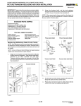
3. Use a flathead screwdriver to unlock the clutches,
grip the screwdriver firmly with both hands and
rotate the clutch 1/4 turn and slowly raise the
clutches to the bottom of the balance tubes. See
figure 2.
You Will Need to Supply
Flathead screwdriver
Phillips screwdriver
Pry bar
Rubber mallet
Side cutter
Pry bar with 90° elbow
NOTE: (for WUDH only) Damage to the lower wood
fillers may occur when removing from jamb carrier and
require replacement. Bottom wood filler part number
W2018.
NOTE: Numbers listed in parentheses ( ) are metric
equivalents in millimeters rounded to the nearest whole
number.
Clutch in released
position
Installation Package
Description
Part Number
1- Pair jamb carrier gaskets
10500510
2-#7 x 7/8" screws
11800727
2-Hardware clips
11860044
2- Clutch pocket plugs
10500504
2- Sash stops
BG-10500524
WH-10500523
2-Check rail pads
BG-10500508
WH10500509
Figure 2
CAUTION
Clutches are under extreme spring tension.
4. Remove the check rail pads. See figure 3.
Jamb Carrier Removal
1. Remove both the top and bottom sash as
described in the Marvin Owner’s Manual.
2. Once the sash have been removed and the
clutches are in a locked position, lightly mark the
clutch heights on the jamb with a pencil. See
figure 1.
Figure 3
5. Remove the head jamb parting stop with a pry bar.
See figure 4.
Clutch in locked
position
Figure 1
2014-09-09
19913634
Figure 4
5.1.1
Marvin Service Manual
Balance Tube Replacement
6. Remove the #7 x 7/8" Phillips head screw. See
figure 5. Skip this step if product was produced
prior to 10/22/2007.
1. Carefully remove the jamb carrier gasket from the
head jamb end of the jamb carrier. Slide both
balance tubes up 3"(76) and remove the existing Shooks. See figure 8.
Figure 5
7. Use the flathead screwdriver to remove the lower
fillers from the jamb hardware assembly. This is
best done by placing the flathead screwdriver into
the space opened by the removed check rail pad.
Loosen both corners of the jamb fillers from the
notches before trying to remove them, to reduce
the possibility of damage to the fillers. See figure 6.
Figure 8
2. Use a pliers to gently lift up 3"-4" (76-102) of the
jamb weather strip from the jamb carrier. See
figure 9. Lower the wood filler about 3" (76).
Figure 9
Figure 6
NOTE: Jamb carriers shipped from the factory will
already be prepped.
NOTE: Remove in a gentle manner taking care so as
not to break or damage the filler. Clad filler shown.
3. Turn the jamb carrier over and remove 1 1/2" (38) of
the jamb carrier between the balance tube and
rivet pins. See figure 10.
8. From the exterior, pry out the jamb hardware
assembly using a pry bar by placing it into the
bottom filler channel, hooking it into the notches on
the side, and levering it out. See figure 7.
Shown from exterior
1 1/2”
Figure 10
Bottom filler channel
Figure 7
2014-09-09
19913634
5.1.2
Marvin Service Manual
4. Install the hanger clip on the top edge of the jamb
carrier between the balance tube and rivet pins.
See figure 11.
2. Seat the jamb assembly facing towards the exterior
first, and press the remainder of the assembly into
the jamb pocket. See figure 14A and figure 14B.
NOTE: If the filler is not fully seated, place a cloth over
the wood filler for protection. Using a rubber mallet;
start tapping at one end and work your way up the filler.
Continue until the filler is fully seated.
3"
Figure 11
5. Slide the balance tubes back down into the hanger
clip hooks until you hear a “click”. See figure 12.
Look down the from the top of the assembly to
insure that the pins are in the proper location on
the hanger clip hooks; if not, pull balance tube back
and repeat step.
A
B
Figure 14
3. Install a #7 x 7/8" Phillips head screw, tighten until
seated. See figure 15. Skip this step if product
was produced prior to 10/22/2007.
Figure 12
NOTE: The wood filler has to be kept below the new
hardware clip in order to install 7/8" long screws
through the clip. After installation slide the filler up to
the pad.
Figure 15
6. Install the top gasket back onto the jamb carrier.
See figure 8.
4. Slide the filler up against the head jamb. Install the
check rail pads and head jamb part stop.
Jamb Carrier Replacement
5. Hold the screwdriver firmly and slide the clutch
assemblies down the jamb carrier to the pencil
marks. See figure 1 and figure 2. Rotate the
balance clutch cam to the open locked position
(cam opening up). Release the screwdriver
carefully from the clutch assembly (it must lock in
place or damage will occur). Compare clutch
height from the sill for the sash affected. They must
be within 1/8" (3) of each other or damage may
occur when sash are reinstalled. Adjust height as
needed.
1. Insert the bottom filler into the jamb hardware
assembly by sliding it into its respective channel.
See figure 13.
6. Reinstall sash and check for proper operation.
Figure 13
2014-09-09
19913634
5.1.3
Marvin Service Manual