1
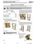
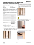
SLIDING DOORS FRAME, SILL AND PANELS
STATIONARY PANEL REMOVAL AND REPLACEMENT
BEFORE YOU BEGIN
Check replacement panel and parts for damage and that the replacement panel has been manufactured with the same
specifications as the panel being replaced, such as size, glazing, finish and lite cut, prior to proceeding with the replacement
of your Ultimate Sliding French Door and Sliding Patio Door Stationary Panels.
NOTE: This instruction can be used to replace the stationary panel on all configurations of sliding doors except on the
non--interlocking stationary panel on the Sliding Patio Door.
INDEX
PARTS NEEDED
Page
1 -- Stationary panel
1 -- Head jamb bracket (2 for IZ3)
4 -- #8 x 1″ flat head screws(8 for IZ3)
4 -- Side jamb brackets (8--0 panel requires 5 brackets)
8--10 -- #7 x 5/8″ flat head screws, side jamb bracket to jamb
8--10 -- #7 x 1 1/4″ flat head screws, side jamb bracket to panel
Stationary Panel Removal . . . . . . . . . . . . . . . . . . . 9.2.2
Stationary Panel Installation . . . . . . . . . . . . . . . . . . 9.2.4
YOU WILL NEED TO SUPPLY
Safety glasses
Hammer
Stiff putty knife
Phillips screwdriver
Hearing protection
Wood block
Rubber mallet
Masonry chisel
Sealant -- ASTM C920 Class NS 25 or equivalent
WARNING! Improper use of hand or power tools
could result in personal injury and/or product
damage. Follow equipment manufacturer’s
instructions for safe operation.
WARNING: Operator Panel is heavy, take care
not to let the panel fall. Assistance is
recommended for this procedure.
Stationary Panel Removal
NOTE: Clad unit shown for illustrative purposes. Unless
otherwise noted all parts are to be saved for reinstalling the
new stationary panel.
Stationary
panel
1.
Sliding door units with screens will need to have the
screen removed and placed aside. For removal refer to
the appropriate instruction for your screen type.
2.
Remove the header and sill bumper blocks from the
stationary side of the unit. See illustration 1.
Panel
guide
Head jamb
Screw
Screw
Operator
panel guide
2
Top bumper
block
Stationary jamb
Head
jamb
4.
Screw
Screw
Bumper
block
Open
operating
panel and allow
door panel to tilt
inward, lift panel
guide off of top stile.
Save for reuse
later. Lift upward on
panel until rollers
are
disengaged
from the sill and
remove from frame.
See illustration 3.
Panel guide
Sill
1
3.
Slide operating panel to the stationary jamb side of the
frame. Remove exposed screws securing the panel guide
to the head jamb. Next, move the operating panel to the
closed position and remove remaining screws securing
the panel guide to the head jamb. See illustration 2.
Operator
panel
3
19972102
10/2007
9.2.2
Marvin Service Manual
11708609
SLIDING DOORS FRAME, SILL AND PANELS
STATIONARY PANEL REMOVAL AND REPLACEMENT
5.
Remove the stationary panel cover by backing out the
three flat head screws fastening it to the head jamb.
Remove the backer rod located between the panel and
header. See illustration 4.
Interior
Cutaway View
Head
jamb
Stationary
panel
Stiff putty
knife
6
Stationary panel
interlock
Head jamb
8.
If your panel has a head jamb bracket, remove the two
screws (or 4 screws for IZ3) and bend the bracket(s) down
until it is parallel with the head jamb. See illustration 7a. If
your panel does not have a head jamb bracket, locate the
screw that is installed through the header and into the
interlocking stile. Cut the screw by using a masonry chisel
and hammer. See illustration 7b.
Head jamb
stationary bracket
Backer
rod
Stationary
panel
4
Remove the condensation cover from the sill by using a
stiff putty knife. Note: The condensation cover is secured
to the sill by a vinyl barb. See illustration 6.
Stationary panel
cover dust block
Stationary panel
cover
Screw
NOTE: Pull down on
jamb side first to remove.
6.
7.
Starting at the top, remove the stationary jamb cover
using a stiff putty knife. Note: The cover is attached to the
jamb by a vinyl barb. See illustration 5.
Stiff putty
knife
Stationary
panel
7a
Head jamb
Masonry
chisel
Stationary
panel
5
Stationary
jamb cover
Sill
7b
10/2007
9.2.3
Marvin Service Manual
11708609
SLIDING DOORS FRAME, SILL AND PANELS
STATIONARY PANEL REMOVAL AND REPLACEMENT
9.
Locate three screws that are installed through the jamb
into the stationary panel. Cut the screws by using a
masonry chisel and hammer and remove the three
stationary jamb fillers. Note: Discard the fillers. See
illustration 8.
Screw through panel
Masonry chisel
Stationary
panel
retainer
Stationary
panel
Leveling
block
Jamb
Sill
Filler block
8
10.
10
Remove the head jamb part stop by inserting a putty knife,
from exterior, between the part stop and header and pry
down gently. See illustration 9.
Installing Stationary Panel
1.
Fasten 4 (5 on 8--0) side jamb brackets to the jamb side
of the stationary interlock panel and/or stationary panel
through the predrilled holes with #7x 1 1/4″ flat head
screws. See illustration 11a.
2.
Fasten stationary head jamb bracket(s) to the stationary
interlock panel through the predrilled holes with #8x1″
flat head screws. See illustration 11b.
1
11a
11.
Long leg
toward
panel
2
9
Slide the stationary panel 1/2″ away from the stationary
jamb to disengage the stile from the jamb. Tilt the
stationary panel in from the top and slide the bottom of
the panel toward the interior to unlock the leveling block
from the stationary panel retainer. Lift and remove the
stationary panel. See illustration 10.
11b
11
3.
NOTE: IZ3 doors will have 2 head jamb brackets.
From the interior place
the stationary panel(s) 6″
away from the jamb at an
approx. 75 degree angle.
For 3 wide units install
non--interlocking panel
first followed by the
stationary
interlocking
panel. See illustration 12.
12
10/2007
9.2.4
Marvin Service Manual
11708609
SLIDING DOORS FRAME, SILL AND PANELS
STATIONARY PANEL REMOVAL AND REPLACEMENT
4.
Insert the panel leveling block with the sill clip. See
illustration 13. Tilt panel to 90 degrees and slide to side
jamb.
Use a stiff putty knife to bend the head jamb brackets
into place. See illustration 16. Fasten the head jamb
bracket to the head jamb with four #8x1″ flat head
screws placed at a 45° angle. See illustration 16.
7.
Stationary panel
Sill aluminum clip
13
5.
Leveling block
Fasten the interlock (and stationary panel) side jamb
brackets to the side jamb (and center jamb for 3 wide
units) with #7x5/8″ flat head screws. See illustration 14.
16
NOTE: IZ3 doors will have 2 head jamb brackets.
8.
Place the dust block end of condensation cover under
interlock and slide into place. Tap until seated with a
wood block and rubber mallet. See illustration 17.
Condensation
cover
Stationary
panel
Condensation
cover
Sill
1
Stationary
panel
14
6.
Leveling
block
Mallet
Reinstall the backer rod between the panel and header.
See illustration 15.
Head
jamb
Wood
block
2
17
9.
Reinstall head jamb part stop. See Illustration 18.
Head
jamb
Backer
rod
Stationary
panel
1
15
Head jamb
stop
18
10/2007
9.2.5
2
Marvin Service Manual
11708609
SLIDING DOORS FRAME, SILL AND PANELS
STATIONARY PANEL REMOVAL AND REPLACEMENT
10.
To reinstall the stationary jamb cover, place sealant with
a continuous bead starting 6″ from sill and continue down
to the end of wood grain and continue along the sill to the
interior oak sill liner. Next install the stationary jamb cover
using a wood block and rubber mallet. See illustration 19.
12.
Reinstall bottom bumper block. See Illustration 21.
Stationary
jamb
Screw
Jamb
Sealant
Bumper
block
Sill
1
21
Jamb cover
13.
Wood
block
Mallet
Jamb
Set the operator panel onto the track. Reinstall the
operator panel guide and top bumper block. See
illustration 22.
Sill
2
19
11.
Operator
panel
Insert dust block end of stationary panel cover over
interlock and slide into place. Fasten the stationary panel
cover with three screws. See illustration 20.
Head jamb
Head jamb
Stationary panel
cover dust block
Operator
panel guide
Stationary
jamb
Stationary panel
cover
Top bumper block
Screw
Stationary panel
interlock
20
Screw
Stationary
panel
22
14.
12/2006
Screw
9.2.6
On units with screens, reinstall screen.
Marvin Service Manual
11708609